LED恒温加热台说明书1
金城春兰 恒温水浴箱HH-US系列使用说明书

HH-US系列恒温水浴箱使用说明金坛区金城春兰实验仪器厂Spring Instrument.Co.,LtdHH-US系列恒温水浴箱·使用说明书·前言首先,感谢您购买金坛区金城春兰实验仪器厂的产品!在您使用本公司的设备之前,请先详细阅读本说明书,并按照本操作规程正确使用仪器。
声明:由于产品的更新换代,手册的内容可能与您的最新产品有稍许差异,在您第一次使用时请咨询现场服务人员。
在你以后的使用中,如果发现问题,请及时与我公司联系,我们会竭诚为你服务。
另外,由于编写者水平有限,手册中难免有不足之处,欢迎指出。
春兰仪器一、安装说明恒温水箱应安装在环境良好的实验室中,地点的选用原则如下表:安置地点的选用原则1 通风良好、无尘凉爽的稳固地面或实验台面;2 避免飞沫、多蒸气的地方;3 避免有可能产生流入、流滞、泄漏易燃气体的地方;4 避免会产生高频的设备(高频电焊机等)附近;5 避免频繁使用酸性溶液的地方;6 避免频繁使用特殊喷雾器(含硫化物之类)的地方;从维修及安装时的操作方便及安全的考虑,应尽可能确保室内机与障碍物之间的空间。
安装室内机时务必确保一下尺寸:1)恒温水箱顶部与顶部障碍物之间距离至少为300mm以上;2)恒温水箱侧面与两侧障碍物距离至少为500mm以上;3)恒温水箱后侧与障碍物之间距离至少为500mm以上;4)恒温水箱前面与障碍物之间距离至少为1000mm以上。
下图所示为装置安装空间要求(单位:mm)。
打开外包装后首先应按照装箱单检查配件是否齐全,如发现短缺等情况请立即反馈给我公司销售服务部门予以解决。
开箱后将恒温水箱装置抬离木制包装底座,平放于宽敞位置,检查本装置周身是否有运输传送中的损坏,确认无误后平推到安装位置,将本装置置于平稳状态,然后接好装置的电源线等。
使用前,建议用湿抹布轻轻擦拭内胆表面,拭去不锈钢表面保护油。
恒温水箱示意图二、技术参数对照表:恒温水箱内箱选用优质304不锈钢和精密机械加工工艺制造,具有耐高温、耐腐蚀的特点。
恒温控制器操作指南说明书
Step 11. Enter to the Thermocouple Type Input Submenu Press d to display flashing, previously selected Thermocouple type.Step 12. Scroll through available selection of TC types Press b to sequence thru flashing Thermocouple types,(select k -for type "K" CHROMEGA TM /ALOMEGA TM )J K T E N DIN J R S B C - TC types J k t E N dN J R S b C - DisplayStep 13. Store TC typeAfter you have selected the Thermocouple type press d to store your selection, the instrument automatically advances to the next menu item.Step 14. Enter to Reading Configuration MenuThe display shows RDG Reading Configuration, which is the top menu for 4 submenus: Decimal Point, Degree Units, Filter Constant and Input/Reading Submenus.Step 15. Enter to Decimal Point Submenu Press dto show DEC Decimal Point.Step 16. Display the Decimal Point positionPress d again to display the flashing Decimal Point position.Step 17. Select the Decimal Point position Press b to select FFF.F Decimal Point position.Step 18. Store selected Decimal Point positionBy pressing d momentarily the Decimal Point position will be stored and the instrument will go to the next menu item.Step 19. Enter to Temperature Unit Submenu Display shows TEMP Temperature Unit.Step 20. Display available Temperature Units Press d to display the flashing Degree °F or °C .Step 21. Scroll through Temperature Units selection Press b to select °F Degree.Step 22. Store the Temperature UnitPress d to display momentarily that the Degree Unit has been stored and the instrument will go automatically to the next menu item.Step 23. Enter the Filter Constant Submenu Display shows FLTR Filter Constant Submenu.Step 24. Display the Filter Constant Value Submenu Press d to display the flashing, previously selected Filter Constant.Step 25. Scroll through available Filter Constants Press b to sequence thru Filter Constants 0001, 0002,0004, 0008, 0016, 0032, 0064and 0128.Step 26. Store the Filter ConstantPress d momentarily to store 0004Filter Constant and the instrument will automatically go to the next menu item.Step 27. Enter Alarm 1 MenuPress a until the ALR1Alarm 1 Menu appears on the Display. In the following steps we are going to DisableLatch, Active Above, Deadband 020.0, and above Setpoint 1Value will activate Alarm 1.Step 28. Select Latch Type SubmenuPress d to display flashing DSBL / ENBL .If flashing DSBL is displayed, press a , if ENBL is displayed, press b until DSBL is displayed, then press d to store and go to the next menu item.Step 29. Select the Above Type of Active Submenu Press d . If flashing ABoV Above is displayed, press a ,otherwise press b until ABoV is displayed. Press d to store and advance to next menu item.WARRANTY/DISCLAIMEROMEGA ENGINEERING, INC. warrants this unit to be free of defects in materials and workmanship for a period of 61 months from date of purchase. OMEGA’s WARRANTY adds an additional one (1) month grace period to the normal five (5) year product warranty to cover handling and shipping time. T his ensures that OMEGA’s customers receive maximum coverage on each product.If the unit malfunctions, it must be returned to the factory for evalua-tion. OMEGA’s Customer Service Department will issue an Authorized Return (AR) number immediately upon phone or written request. Upon examination by OMEGA, if the unit is found to be defective, it will be repaired or replaced at no charge. OMEGA’s WARRANTY does not apply to defects resulting from any action of the purchaser, includ-ing but not limited to mishandling, improper interfacing, operation outside of design limits, improper repair, or unauthorized modifica-tion. This WARRANTY is VOID if the unit shows evidence of having been tampered with or shows evidence of having been damaged as a result of excessive corrosion; or current, heat, moisture or vibration; improper specification; misapplication; misuse or other operating conditions outside of OMEGA’s control. Components in which wear is not warranted, include but are not limited to contact points, fuses, and triacs.OMEGA is pleased to offer suggestions on the use of its vari-ous products. However, OMEGA neither assumes responsibil-ity for any omissions or errors nor assumes liability for any damages that result from the use if its products in accordance with information provided by OMEGA, either verbal or writ-ten. OMEGA warrants only that the parts manufactured by the company will be as specified and free of defects. OMEGA MAKES NO OTHER WARRANTIES OR REPRESENTATIONS OF ANY KIND WHATSOEVER, EXPRESSED OR IMPLIED, EXCEPT THAT OF TITLE, AND ALL IMPLIED WARRANTIES INCLUDING ANY W ARRANTY OF MERCHANTABILITY AND FITNESS FOR A PARTICULAR PURPOSE ARE HEREBY DISCLAIMED. LIMITATION OF LIABILITY: The remedies of purchaser set forth herein are exclusive, and the total liability of OMEGA with respect to this order, whether based on contract, warran-ty, negligence, indemnification, strict liability or otherwise, shall not exceed the purchase price of the component upon which liability is based. In no event shall OMEGA be liable for consequential, incidental or special damages.CONDITIONS: Equipment sold by OMEGA is not intended to be used, nor shall it be used: (1) as a “Basic Component” under 10 CFR 21 (NRC), used in or with any nuclear installation or activity; or (2) in medical appli-cations or used on humans. Should any Product(s) be used in or with any nuclear installation or activity, medical application, used on humans, or misused in any way, OMEGA assumes no responsibility as set forth in our basic WARRANT Y/DISCLAIMER language, and, additionally, purchaser will indemnify OMEGA and hold OMEGA harmless from any liability or damage whatsoever arising out of the use of the Product(s) in such a manner.RETURN REQUESTS/INQUIRIESDirect all warranty and repair requests/inquiries to the OMEGA Customer Service Department. BEFORE RE URNING ANY PRODUC (S) O OMEGA, PURCHASER MUS OB AIN AN AUTHORIZED RETURN (AR) NUMBER FROM OMEGA’S CUSTOMER SERVICE DEPART MENT (IN ORDER T O AVOID PROCESSING DELAYS). T he assigned AR number should then be marked on the outside of the return package and on any correspondence.FOR WARRANTY RETURNS, please have the followinginformation available BEFORE contacting OMEGA:1. Purchase Order number under which the product was PURCHASED,2.3. Model and serial number of the product under warranty, and Repair instructions and/or specific problems relative to the product.FOR NON-WARRANTY REPAIRS, consult OMEGA for current repair charges. Have the following information available BEFORE contacting OMEGA:1. P urchase Order number to cover the COST of the repair or calibration,2.3.Model and serial number of the product, and R epair instructions and/or specific problems relative to the product.OMEGA’s policy is to make running changes, not model changes, whenever an improvement is possible. This affords our customers the latest in technology and engineering.OMEGA is a trademark of OMEGA ENGINEERING, INC.© Copyright 2018 OMEGA ENGINEERING, INC. All rights reserved. T his document may not be copied, photocopied, reproduced, translated, or reduced to any electronic medium or machine-readable form, in whole or in part, without the prior written consent of OMEGA ENGINEERING, INC.MQS 3720/0818This Quick Start Reference provides information onsetting up your instrument for basic operation. Thelatest complete Communication and OperationalManual as well as free Software and ActiveXControls are available at or onthe CD-ROM enclosed with your shipment.The instrument is a panel mount device protected in accordance with EN 61010-1:2001, electrical safety requirements for electrical equipment for measurement, control and laboratory.Remember that the unit has no power-on switch. Building installation should include a switch or circuit-breaker that must be compliant to IEC 947-1 and 947-3. SAFETY:•Do not exceed voltage rating on the label located onthe back of the instrument housing.•Always disconnect power before changing signal andpower connections.•Do not use this instrument on a work bench withoutits case for safety reasons.•Do not operate this instrument in flammable orexplosive atmospheres.EMC:•Whenever EMC is an issue, always use shielded cables.•Never run signal and power wires in the same conduit.•Use signal wire connections with twisted-pair cables.•Install Ferrite Bead(s) on signal wire close to theinstrument if EMC problems persist.。
恒温显示器 RA00118AA_U-01PC-13W38 用户手册说明书

用户手册恒温显示器R A 00118A A _U -01P C -13W 38恒温显示器用户手册目录恒温显示器用户手册1 恒温显示器 41.1 功能 41.2 设备类型? 42 说明 52.1 图标和按键说明 52.2 功能和操作模式简要说明 63 恒温器使用 73.1 MyHOME温度调节设备的探测器(有中控) 73.2 酒店房间的恒温器 103.3 单体家居设备 144 维护 184.1 出现错误 18恒温显示器用户手册1 恒温显示器1.1 功能恒温显示器可调节室内温度(制热或制冷)并根据需要配置不同的应用。
1.2 设备类型?有中控的MyHOME温度调节设备(参见第3.1章节)设置在恒温器内的传感器可作为MyHOME设备的主探测器,在这种情况下,恒温器将接收来自设备中控的设置。
酒店房间的设备(参见第3.2章节)用于酒店房间的恒温器配置可使客人简便地设置温度并获得需要的舒适度。
酒店的管理者还可将每个房间内的恒温器整合在一起,通过专门的软件组成管理系统,对能耗进行监控,避免无益的浪费。
单体家居设备(参见第3.3章节)作为第三种使用类型,室内恒温器可对家居单体设备进行温度调节,无需其它控制装置。
恒温显示器用户手册2 说明2.1 图标和按键说明1 - 制热功能。
2 - 制冷功能。
3 - 操作模式的图标(参见第2.2章节)。
4 - “模式”按键 (MODE):短按可改变工作模式;长按(除作为MyHOME的探测器使用之外)可改变功能。
5 - 按键 + :增加设置值。
6 - 按键 – :减少设置值。
7 - “风扇”按键 (FAN):设置盘管风机的风扇速度,有3个水平和自动8 - 启动制热/制冷说明(参见第2.2章节)。
9 - 盘管风机的风扇速度说明,有3个水平。
10 - 盘管风机的风扇为自动模式的说明。
11 - 测得温度(温度计图示亮起)和温度设置(温度计图示熄灭)的说明。
12 - 温度单位°C或 °F。
恒温箱的操作指南说明书
恒温箱的操作指南说明书一、概述恒温箱是一种专用设备,用于提供恒定的温度环境,广泛应用于实验室、医疗保健、食品加工等领域。
它具有温度控制精确、稳定性好、操作简便等特点,本操作指南将为您介绍恒温箱的使用方法和注意事项。
二、设备介绍1. 外观特点恒温箱采用不锈钢材质制作,外观整洁美观,具有耐腐蚀、防锈、易清洁等特性。
2. 控制面板恒温箱的控制面板上配有温度设置按钮、温度显示屏、时间设置按钮、湿度控制按钮等功能,操作简单方便。
3. 温度控制系统恒温箱采用先进的温度控制系统,可以精确控制设定温度,并具有恒温、恒湿、急速变温等功能。
三、使用方法1. 准备工作a) 将恒温箱放置于通风良好的平稳台面上,避免阳光直射、潮湿环境和易燃物品附近。
b) 检查电源线是否完好无损,并将其插入可靠的电源插座。
c) 确保恒温箱内部干净整洁,没有杂物和水迹。
2. 打开恒温箱按下电源按钮,待显示屏亮起后,恒温箱即可工作。
3. 设置温度a) 按下温度设置按钮,显示屏上将出现温度设定界面。
b) 通过调节温度设置按钮,设定所需的温度值。
c) 按下确认按钮,系统将根据设定温度值开始升温直至设定温度。
4. 恒温使用a) 当恒温箱达到设定温度后,将样品放入箱内,并关闭箱门。
b) 确保恒温箱工作环境内的温湿度达到设定要求,使样品得到恒定温度的作用。
c) 定期检查恒温箱内部温度显示,并确保温度保持在设定范围内。
5. 急速变温部分恒温箱具有急速变温功能,可以快速降温或升温。
操作方法如下:a) 按下急速变温按钮,显示屏将出现快速设定温度的界面。
b) 通过调节急速变温按钮,设定所需的变温速率。
c) 按下确认按钮,系统将根据设定的变温速率进行急速降温或升温。
四、注意事项1. 遵循使用规程请按照恒温箱的使用规程使用设备,禁止超负荷操作,以免损坏设备或引发意外。
2. 温度控制在设定温度时,请选择合适的温度值,避免过高或过低的温度对样品造成损伤或影响实验结果。
恒温电子恒温器手册说明书

Fan coil units3PictogrammesManual cool/heat changeoverAutomatic cool/heat changeover based on water temperatureAutomatic cool/heat changeover based on air temperatureControl of the 3-way/4-port ON/OFF valve. The water valve shut-off once the desired temperature is reached.The controller controls the electric heater as integration or replacement of the hot water heating system. When the operating mode selector witch is turned on “electric heater” and the electric heater is turned on, the fan runs continuously at medium speed.The fan speed can be set at one of the 3 speeds (low, medium or maximun) by turning the operation mode selector.The fan speed is switched automatically based on the difference between the temperature set on the thermostat and the room temperature.Optimised comfort cooling. When the fan coil has reached the desired setpoint, the fan will operate at medium speed and at regular intervals to ensure constant room temperature and lower sound.The controller prevents the fan coil unit from operating in one mode, if the required water temperature is not achieved to operate in the selected mode.The dead zone is a temperature interval close to the set temperature. When the air is warmer/cooler than the top/lower limit of the neutral zone, the cooling/ heating mode is selected.FWV FWL FWM01234567891011kWFWD24681012141618202224kWFWB24681012141618202224kWFan Coil Reference 2-pipe4-pipeProduct portfolioFan Coil Reference 2-pipe4-pipeCooling HeatingFan Coil Reference 2-pipe4-pipeDaikin fan coil units deliver quiet, reliable, controllable comfort of air conditioning without all the noise of other central systems.Fan coil units are a highly efficient means of turning a water chiller or hot water boiler into an efficient, quiet air conditioning system.The units are super quiet because the only moving part is the fan; making them ideal for use in offices, hotels and the home.The new range of fan coil units offers 5 models, of which 3 in flexible application. A wide range of accessories is available.For the ultimate in quiet, controllable air conditioning with all the comfort but none of the bulk or noise, the clear choice is Daikin.Easy to installFast and easy field set up, ready for use!KEY HOLE SYSTEM / LEVELLING•Quick fixing system for wall/ceiling mounting Advantage : No need to unscrew the nut •Units just need to be perfectly leveledAdvantage : No need to calculate the condensate drainageWATER CONNECTION •Pre-assembled 3-way/4-port ON/OFF valves are available •Valve packages are insulated, no extra drain pan required •Valve packages contain balancing valves and sensor pocket •Valve packages can be factory-mounted and are leak tested•Same valve package can be installed vertically and horizontally, on the right or on the left side of the unit without changeAdvantage : Easy to connect even when space is limitedCONDENSATE DRAINAGE•Condensate drain pan features slopes to reduce water accumulation •Supplied with flexible rubber hose pipe for easy connectionAdvantage : Eliminates the need to align drain pan outlet with customer pipingAdvantage : No need for collar if pipe diameter is compatibleQUICK ELECTRICAL CONNECTIONS•Fast-on connections for electrical options : no tools needed •Controls are already factory-wired and testedAdvantage : Control panel no longer needs to be opened (external customer connections)•Wiring diagram on the cover of the electrical boxEasy to maintainLow maintenance and high effeciency QUICK REMOVAL OF WASHABLE FILTER•No tools needed•Same system on vertical and horizontal unitsAdvantage: very fast filter removalELECTRIC HEATER RESETTING•No relay up to 2kW capacityAdvantage: even quieter operation•Manual reset easily accessible•Equipped with two overheat cut-out thermostats(manual & automatic reset)Advantage: anticipates the upcoming standardsFAN MOTOR/CONTROL PANEL ACCESSIBILITY• 4 screws to access to the fan motor•Fan board is removable without bringing the unit down•Motor is life-lubricated and has a life span of 40,000 hours•Control panel removable by a single screw•Can be unfolded for a better component access•Removable grilles•Easy access to control valvesSTRUCTURE•Modular concept•Height of the units only 240mm for all the sizes•Cooling coil and fan module is made of:-galvanised sheet steel-internally insulated (with 3mm close-cell polyurethane)•Key-hole system for fast mounting•Rubber anti-vibration damper to isolate the unit from supporting structure •Straight duct connector is mounted to both suction and discharge side (width 30mm)• A template is available in the carton box for easy connection to the ceiling HEAT EXCHANGER•3, 4 or 6 stage row cooling coil•Standard left handed water connections + air-purge(water connections can easily be turned)•Drain pan can to collect the condensate from:-Heat exchanger-Regulating valvesFAN MOTOR ASSEMBLY•1, 2 or 3 centrifugal fans with forward profile blades, dynamically andstatically balanced•7-speed electrical motors (with thermal protection on windings)•All 7 speeds pre-wired in the factory in the terminal block of the switch box •To reduce the requested installation space is the terminal block located onthe same side as the water connectionsAIR FILTER•Located in the air inlet•Removable from the bottom•Made of acrylic fiber, filter class EU2STRUCTURE•Possibility of installation both in horizontal and vertical position•Reduced height 280mm up to model 10•The unit is made of:- galvanised sheet steel- insulated with noise-proof/anti-condensing material(self-extinguishing in Class 1, with a thickness of 10mm)•Key-hole system for fast mounting•Straight duct connector is mounted to discharge side(width 30mm)HEAT EXCHANGER• 1 or 2 stage row cooling coil•Standard left handed water connections + air-purge•System for collecting and discharging condensate setup either for ceiling or wall mounting.FAN MOTOR ASSEMBLY•Dual intake centrifugal fans made of aluminum, dynamically and statically balanced •3-speed electric motor, installed on vibration damping supports(with thermal protection on windings)AIR FILTER•Air-intake module + Filter is standard delivered with each unit•Removable filter from the bottom•Made of acrylic fiber, filter class EU2EPIMSA6EPIA6FWV/L/M FWB FWD01y02y y03y y04y y y05y06y yx /v07y 08yx /v x /v09x /v 10yx /v x /v12v 16v 18vy v /x vEasy to control !The new fan coil units can be operated by 3 different controllers:• electronic control built-in (ECFWEB6)• electronic control remote (ECFWER6)• electromechanical control built-in (ECFWMB6)The electronic control consists of:•Operating mode selector , to turn the fan coil on and off,to choose the type of operating mode (automatic or at fixed speed) and to control the electric heating.•Cooling / Heating selector•Operational LEDs that indicates the current operation mode•Thermostat to control the room temperature•Free contacts for external enabling signal that may switch on or off the unit.• Free contacts for centralized cool/heat changeover • Water temperature probe • Air temperature probeSeveral configurations are possible by changing dip switches.The electromechanical controller includes a fan speed selector (3 speeds + stop) and manual cool/heat changeover. In case of the on/off valves, control can also be done through this controller.Power interface / master slave interfaceAn additional interface is required for units with a current greater than 1,12A.Master slave interface (EPIMSA6: 4x3A)For remote control of up to 4 fan coil units, an optional master/slave interface can be installed. Up to 3 EPIMSA6can be connected in parallel (--> max. 12 fan coils).Power interface (EPIA6: 1x16A)This is absolutely required for connection of ECFWER6 to FWD12 to18. It can be used as an alternative for EPIMSA6for all other fan coils.Master slave interface is only needed in case of remote control of multiple fan coil unitsObigation to use master slave interface or power interface Obligation to use power interfaceControl featuresBasic control functionsOptionsCooling/heating changeover2-p i p e4-p i p eCOOLINGTotal capacity (H)kW Sensible capacity (H)kW Water flow l/h Pressure drop kPa HEATINGHeating capacity (H)kW Water flow l/h Pressure drop kPa Power input HW Coil water volume lAir flowH/M/L m 3/h Sound power level H/M/L dBA WeightFWV kg FWM kg FWL kg COOLINGTotal capacity (H)kW Sensible capacity (H)kW Water flow l/h Pressure drop kPa Cooling coil water volume l HEATINGHeating capacity (H)kW Water flow l/h Pressure drop kPa Heating coil water volume l Power input H W Air flowH/M/L m 3/h Sound power level H/M/L dBA WeightFWV kg FWM kg FWL kgWater connections inch Max. absorbed current WDimensions FWV/FWL mm FWM mmPower supplyV/~/HzFWV/FWL/FWM01-10C**010203040608101.542.09 2.93 4.33 4.77 6.718.711.20 1.51 2.113.15 3.654.91 6.382653595047458201,1541,498131311121412192.14 2.79 3.815.636.367.8311.12653595047458201,1541,498910991091336466287891822440.50.71 1.4 1.4 2.1 2.1319/233/178344/271/211442/341/241706/497/361785/605/4701,011/771/5701,393/1,022/64247/39/3452/44/3650/44/3855/48/4059/52/4459/52/4466/58/481920253031414114151923233232202127323344441.5 1.79 2.87 4.26 4.67 6.648.551.17 1.46 2.07 3.09 3.57 4.85 6.262583084947338031,1421,471131311121412190.50.71 1.4 1.4 2.1 2.12.23 2.07 2.91 4.51 4.677.919.301961822863964656948167851010890.20.20.30.40.40.60.63659628789182244307/225/174327/261/205431/332/238690/490/356763/593/460998/765/5651,362/1,007/63647/39/3454/48/4250/45/3855/48/4059/53/4659/52/4466/58/482021263233444415162025253434212228343546461/2"1/2"1/2"1/2"1/2"3/4"3/4"0.160.210.270.390.380.80 1.12564x774x226564x984x226564x1,194x226564x1,404x251535x584x224535x794x224535x1,004x224535x1,214x249230/1/5001020304060810FWV FWL FWM ESRH02A6ESRH03A6ESRH06A6ESRH10A6x x x EEH01A6EEH02A6EEH03A6EEH06A6EEH10A6x x x E2MV03A6E2MV06A6E2MV10A6x x x E4MV03A6E4MV06A6E4MV10A6x x x YFSTA6xx x EAIDF02A6EAIDF03A6EAIDF06A6EAIDF10A6--x ESFV06A6ESFV10A6x -x ESFVG02A6ESFVG03A6ESFVG06A6ESFVG10A6x --EFA02A6EFA03A6EFA06A6EFA10A6x -x ERPV02A6ERPV03A6ERPV06A6ERPV10A6x x -ECFWMB6x x -ECFWEB6x x -ECFWER6x x x EPIMSA6x x x EDPVA6x x x EDPHA6-xx2-p i p e ( **= T N o r T V )4-p i p e ( **= F N )** = T N (2-p i p e , w i t h o u t v a l v e s ), T V (2-p i p e , w i t h v a l v e s ), F N (4-p i p e , w i t h o u t v a l v e s )Additional single row heat exchanger*Electric heater**2-pipe ON-OFF 3-way motor driven valve with complete mounting kit*4-pipe ON-OFF 3-way motor driven valve with complete mounting kit*(**)Fan stop thermostat**(only for ECFWMB6)Air intake & discharge grille +front filter fixing kit for concealed models Supporting feet(= supporting brackets + covers)Supporting feet + grille Manual fresh air intake louver Rear panel for vertically installed units Controller - electromechanical built-in**Controller - electronic built-in + water probe**Controller - electronic remote + water probe Power interface for connection of up to 4 FCU to a single control panel Vertical drain pan Horizontal drain panOption description * C a n b e o r d e r e d f a c t o r y m o u n t e d ** f a c t o r y m o u n t e d o n r e q u e s tMeasuring conditions (at nominal air flow and ESP) COOLING • Air temperature entering the unit: 27°C/19°C • Water temperature entering the unit 7°C • Water temperature rise 5 KHEATING • Room air temperature 20°C • For 2 pipe units : Water inlet temperature 50°C - Water flow rate same as for the cooling test • For 4 pipe units : - Water inlet temperature 70°C - Water temperature decrease 10 KFWB02-10AT 10Additional heat exchanger 3-way valve std h/e 3-way valve add. h/e 2-way valve std h/e 2-way valve add. h/e Electric heater Fan stop thermostat Power interface (*)Master slave interface (*)Controller electronic - remoteOption description 020304050607080910EAH04A6EAH07A6EAH10A6factory mounted on requestE2MV307A6E2MV310A6factory mounted on requestE2MV207A6E2MV210A6factory mounted on requestYFSTA6-EPIA6EPIMSA6ECFWER60203040506070809104008001,2007165592.61 3.14 3.49 5.08 5.45 6.477.578.6710.341.88 2.16 2.34 3.6 3.87 4.4 5.23 5.96 6.94485395988739361,1111,2991,4881,77481411158142121265.47 6.01 6.4710.3111.3912.2815.0516.8518.784805275679049991,0771,3191,4791,647710812710161518232426313335434548239x1,039x609239x1,389x609239x1,739x6093.14 5.9912.82755261,1233587917239x788x243239x1,138x243239x1,497x3351061922940.510.94 1.28586069230V/1~/50HzFWB2-p i p e /4-p i p e Air flow ratem 3/h Available static pressure Pa COOLINGTotal capacity (H)kW Sensible capacity (H)kW Water flow l/h Pressure drop kPa HEATINGHeating capacity (H)kW Water flow l/h Pressure dropkPa Machine weight kg Dimensions (HxWxD)mm HEATINGHeating capacity (H)kW Water flow l/h Pressure dropkPa Weight kg Dimensions mm Power input (H)W Running curent (H)A Sound power level (H)dBAPower supply2-p i p eA d d . H e a t e x c h a n g e rMeasuring conditionsCOOLING 2-pipe: air: 27°CDB/19°CWB - entering water 7°C - leaving water 12°C HEATING 2-pipe: air: 20°CDB - entering water 70°C - leaving water 60°CSound power level according to ISO3741 - sound pressure calculated at 1.5m distance - Q=2(*) In combination with ECFWER6, EPIMSA6 or EPIA6 must be installed for FWB08-1011Notes:1. The valves for FWD12-16-18 do not contain piping nor drain pan.2. Requires electronic control.3. Neglecting the absolute requirement to install an additional interface (EPIA6 or EPIMSA6) to FWD06 -->18 may cause fire or other damage to the equipment.4. In combination with ECFWER6, EPIMSA6 or EPIA6 must be installed for FWD06-10.5. In combination with ECFWER6, EPIA6 must be installed for FWD12-18.Electric heater: small (2)Electric heater: big (2)2-pipe 3-way valve (1)4-pipe 3-way valve (1)Vertical drain pan Horizontal drain pan Fan stop thermostatFresh air intake louvers (motorised) Controller - electronic remote + water probe (3)Master / Slave Interface (4)Power interface (5)Option description 2- p i p e / 4-p i p eCOOLINGTotal capacity kW Sensible capacity kW Water flow (H)l/h Pressure drop (H)kPa HEATINGHeating capacity kW Water flow (H)l/h Pressure drop (H)kPa Available static pressure Pa Weight kg COOLINGTotal capacity kW Sensible capacity kW Water flow (H)l/h Pressure drop (H)kPa HEATINGHeating capacity kW Water flow (H)l/h Pressure drop (H)kPa Available static pressure Pa Weight kg Air flow rate m 3/h Power input W Water connections inch Max. absorbed current A Dimensions mm Sound power level OveralldBA Power supplyV/~/HzFWD04-18A*2-p i p e ( *= T )4-p i p e ( *= F )Measuring conditions (at nominal air flow and ESP) COOLING • Air temperature entering the unit: 27°C/19°C • Water temperature entering the unit 7°C • Water temperature rise 5 KHEATING • Room air temperature 20°C • For 2 pipe units : Water inlet temperature 50°C - Water flow rate same as for the cooling test • For 4 pipe units : - Water inlet temperature 70°C - Water temperature decrease 10 K040608101216183.90 6.207.808.8211.9016.418.33.08 4.65 6.527.369.3612.814.16741,0641,3391,5142,0562,8333,140172424162634454.057.719.4310.7914.4519.8121.926741,0641,3391,5142,0562,8333,140142020132128376658686497145134334147496577803.90 6.207.808.8211.9016.418.33.08 4.65 6.527.169.3612.814.16741,0641,3391,5142,0562,8333,140172424162634454.49 6.629.219.2115.8621.1521.153495818088081,3921,8561,85691513131216166353635992138128354350527183868001,2501,6001,6002,2003,0003,0001772743153255309911,0013/43/43/43/41110.95 1.58 1.971.97 3.21 5.375.37280x754x559280x964x559280x1,174x559352x1,174x718352x1,384x71866697272747878230/1/5004060810121618EDEH04A6EDEHS06A6EDEHS10A6EDEHS12A6EDEHS18A6EDEH04A6EDEHB06A6EDEHB10A6EDEHB12A6EDEHB18A6ED2MV04A6ED2MV10A6ED2MV12A6ED2MV18A6ED4MV04A6ED4MV10A6 2 x ED2MV12A62 x ED2MV18A6EDDPV10A6EDDPV18A6EDDPH10A6EDDPH18A6YFSTA6EDMFA04A6EDMFA06A6EDMFA10A6EDMFA12A6EDMFA18A6ECFWER6EPIMSA6----EPIA6FWDE P C E 04-25B / C D / 04/06 L a M o v i d a P r i n t e d o n n o n -c h l o r i n a t e d p a p e r / P r i n t e d i n B e l g i u mDaikin products are distributed by:Zandvoordestraat 300B-8400 Oostende, Belgium The present publication is drawn up by way of information only and does not constitute an offer binding upon Daikin Europe N.V .. Daikin Europe N.V . has compiled the content of this publication to the best of its knowledge. No express or implied warranty is given for the completeness, accuracy, reliability or fitness for particular purpose of its content and the products and services presented therein. Specifications are subject to change without prior notice. Daikin Europe N.V . explicitly rejects any liability for any direct or indirect damage, in the broadest sense, arising from or related to the use and/or interpretation of this publication. All content is copyrighted by Daikin Europe N.V .Daikin Europe N.V . is approved by LRQA for its Quality Management System in accordance with the ISO9001standard. ISO9001 pertains to quality assurance regarding design, development, manufacturing as well as to services related to the product.ISO14001 assures an effective environmental management system in order to help protect human health and the environment from the potential impact of our activities, products and services and to assist in maintaining and improving the quality of the environment.Daikin units comply with the European regulations that guarantee the safety of the product.Daikin Europe NV participates in the Eurovent Certification Programme for Air Conditioners (AC),Liquid Chilling Packages (LCP) and Fan Coil Units (FC); the certified data of certified models are listed in the Eurovent Directory.Daikin’s unique position as a manufacturer of air conditioning equipment, compressors and refrigerants has led to its close involvement in environmental issues. For several years Daikin has had the intention to become a leader in the provision of environmental friendly products. This challenge demands the eco design and development of a wide range of products and an energy management system; which involves energy conservation and reduction of waste.。
恒温加热培养箱使用说明书

恒温加热培养箱使用说明书感谢您选择使用我们的恒温加热培养箱。
本使用说明书将详细介绍如何正确使用和操作此设备,以确保您顺利完成实验工作。
请在操作前仔细阅读本说明书,并按照指导进行操作。
一、产品概述恒温加热培养箱是一种用于生物实验室及其它科学研究领域的设备,用于提供适宜的温度和湿度条件,以促进生物样品、微生物培养物以及细胞培养等相关实验的进行。
本设备适用于医疗、制药、生物工程等领域,具有稳定性高、操作简便等特点。
二、安全提示1. 在操作设备之前,请确保已读懂并理解本手册中提供的全部信息。
2. 请接地插头以确保人身安全。
3. 使用设备时,请确保周围通风良好,不得堵塞排气口。
4. 请不要在加热培养箱上方放置易燃、易爆等危险物品。
5. 关闭设备前,请确保温度已经达到室温并且所有设定参数已重置。
6. 当设备出现故障时,请立即与维修部门联系,不得私自拆解修复。
三、设备操作1. 开机和关机a. 将电源插头插入电源插座,确保电源供应稳定。
b. 打开设备主电源开关,显示屏将显示当前室内温度。
c. 进行加热培养箱操作前,请确保箱内无其它杂物。
d. 关闭设备主电源开关,显示屏将关闭。
2. 温度设定和调节a. 按下“模式”按钮,显示屏将显示当前操作模式。
b. 按下“温度”按钮,显示屏将显示当前设定温度。
c. 通过“温度”按钮的上下调节键,将设定温度调整至需要的数值。
d. 按下“确认”按钮,设备将开始工作,温度将保持设定值。
3. 湿度设定和调节a. 按下“模式”按钮,显示屏将显示当前操作模式。
b. 按下“湿度”按钮,显示屏将显示当前设定湿度。
c. 通过“湿度”按钮的上下调节键,将设定湿度调整至需要的数值。
d. 按下“确认”按钮,设备将开始工作,湿度将保持设定值。
4. 定时设定a. 按下“定时”按钮,显示屏将显示当前定时设置。
b. 通过“定时”按钮的上下调节键,将设定定时调整至需要的数值。
c. 按下“确认”按钮,设备将在设定时间后自动关闭。
电热恒温培养箱 使用说明书

使用说明书●此"使用说明书"务请送至最终操作人员手中!●在开始操作之前务请阅读并理解"使用说明书"的全部内容.对于误操作而引起的不良后果,本公司概不负责。
●"使用说明书"中的内容在今后可能进行变更与完善,到时公司将不另行通知,敬请谅解。
●客户在使用过程中如发现异常现象,请及时与本公司联系。
●阅读"使用说明书"请妥善保管以随时查阅,同时请务必填妥并寄出您的保修卡(寄至本公司售后服务中心)。
产品型号DHP-制造编号制造日期目录(一)安全提示 (2)(二)概述 (3)(三)结构简介 (3)(四)技术指标 (3)(五)工作原理 (3)(六)安装与调试 (3)(七)温度设定法 (4)(八)安全注意事项 (5)(九)维修及保养 (5)(十)电器原理图 (5)(十一)故障处理 (6)(十二)其他 (7)(一)安全提示请用户务必遵守以下所列各项安全注意事项1.培养箱必须有效接地。
2.必须使用与培养箱要求一至的电源。
3.不允许随意接长或剪短产品电源连线。
4.不允许放易燃、易爆、易挥发及含有腐蚀性的物品进行干燥烘培。
5.不得将手或物件随意插入进风或出风口。
6.培养箱出现故障,务必请专业人员进行维修。
安全警告1.必须充分阅读理解干燥箱使用说明书后,才可进行操作。
2.更换熔断器及电器部分维修时必须拔下电源插头。
3.培养箱长期不用,必须拔下电源插头。
(二)概述电热恒温培养箱是工农业生产、科学研究、大学、仪器医疗卫生等,单位实验室的必需设备,供细菌培养、育种、发酵及温度不高于60℃的其它恒温试验用.(三)结构1.本产品外壳体用优质薄钢板冲压而成,表面喷塑,内胆为SUS304不锈钢,双重密封,保温材料为优质硅酸棉.箱内装有微型风扇,微风循环,箱内温度均匀.2.温控装置采用自适应温度控制液晶显示,无须控温参数调节,控温精度高,无超调,具有定时功能,超温保护功能,定时时间9999分钟.3.电器控制部分在顶部,使用维护方便.(四)技术指标型号DHP-9012DHP-9032DHP-9052DHP-9082DHP-9162DHP-9272电源电压220V50Hz控温范围RT+5~65℃温度分辩率/波0.1℃±0.5℃动度输入功率180W200W250W350W550W700W 内胆尺寸250*260*250340*320*320345*355*410400*400*500500*500*650600*600*750外形尺寸530*480*420620*490*490470*470*680520*520*780640*640*920740*740*1035载物托架(标配)2块(五)电器工作原理打开电源开关,仪表上电,设定所需要的温度和时间仪表自动控制加热,加热元件为加热膜,控制原件为双向控硅,仪表控制原理为自适应控制。
恒温控制器用户操作指南说明书
Step 11. Enter to the Thermocouple Type Input Submenu Press d to display flashing, previously selected Thermocouple type.Step 12. Scroll through available selection of TC types Press b to sequence thru flashing Thermocouple types,(select k -for type "K" CHROMEGA ®/ALOMEGA ®)J K T E N DIN J R S B C - TC types J k t E N dN J R S b C - DisplayStep 13. Store TC typeAfter you have selected the Thermocouple type press d to store your selection, the instrument automatically advances to the next menu item.Step 14. Enter to Reading Configuration MenuThe display shows RDG Reading Configuration, which is the top menu for 4 submenus: Decimal Point, Degree Units,Filter Constant and Input/Reading Submenus.Step 15. Enter to Decimal Point Submenu Press d to show DEC Decimal Point.Step 16. Display the Decimal Point positionPress d again to display the flashing Decimal Point position.Step 17. Select the Decimal Point position Press b to select FFF.F Decimal Point position.Step 18. Store selected Decimal Point positionBy pressing d momentarily the Decimal Point position will be stored and the instrument will go to the next menu item.Step 19. Enter to Temperature Unit Submenu Display shows TEMP Temperature Unit.Step 20. Display available Temperature Units Press d to display the flashing Degree °F or °C .Step 21. Scroll through Temperature Units selection Press b to select °F Degree.Step 22. Store the Temperature UnitPress d to display momentarily that the Degree Unit has been stored and the instrument will go automatically to the next menu item.Step 23. Enter the Filter Constant Submenu Display shows FLTR Filter Constant Submenu.Step 24. Display the Filter Constant Value Submenu Press d to display the flashing, previously selected Filter Constant.Step 25. Scroll through available Filter Constants Press b to sequence thru Filter Constants 0001, 0002,0004, 0008, 0016, 0032, 0064and 0128.Step 26. Store the Filter ConstantPress d momentarily to store 0004Filter Constant and the instrument will automatically go to the next menu item.Step 27. Enter Alarm 1 MenuPress a until the ALR1Alarm 1 Menu appears on the Display. In the following steps we are going to DisableLatch, Active Above, Deadband 020.0, and above Setpoint 1Value will activate Alarm 1.Step 28. Select Latch Type SubmenuPress d to display flashing DSBL / ENBL .If flashing DSBL is displayed, press a , if ENBL is displayed, press buntil DSBL is displayed, then press d to store and go to the next menu item.Step 29. Select the Above Type of Active Submenu Press d . If flashing ABoV Above is displayed, press a ,otherwise press b until ABoV is displayed. Press d to store and advance to next menu item.MQS3716-SM/0305iLD24 Big Display Universal Temperature&ProcessSimplified Menu (-SM)WARRANTY/DISCLAIMEROMEGA ENGINEERING, INC. warrants this unit to be free of defects in materials and workmanship for a period of 61 months from date of purchase. OMEGA’s WARRANTY adds an additional one (1) month grace period to the normal five (5) year product warranty to cover handling and shipping time. T his ensures that OMEGA’s customers receive maximum coverage on each product.If the unit malfunctions, it must be returned to the factory for evalua-tion. OMEGA’s Customer Service Department will issue an Authorized Return (AR) number immediately upon phone or written request. Upon examination by OMEGA, if the unit is found to be defective, it will be repaired or replaced at no charge. OMEGA’s WARRANTY does not apply to defects resulting from any action of the purchaser, includ-ing but not limited to mishandling, improper interfacing, operation outside of design limits, improper repair, or unauthorized modifica-tion. This WARRANTY is VOID if the unit shows evidence of having been tampered with or shows evidence of having been damaged as a result of excessive corrosion; or current, heat, moisture or vibration; improper specification; misapplication; misuse or other operating conditions outside of OMEGA’s control. Components in which wear is not warranted, include but are not limited to contact points, fuses, and triacs.OMEGA is pleased to offer suggestions on the use of its vari-ous products. However, OMEGA neither assumes responsibil-ity for any omissions or errors nor assumes liability for any damages that result from the use if its products in accordance with information provided by OMEGA, either verbal or writ-ten. OMEGA warrants only that the parts manufactured by the company will be as specified and free of defects. OMEGA MAKES NO OTHER WARRANTIES OR REPRESENTATIONS OF ANY KIND WHATSOEVER, EXPRESSED OR IMPLIED, EXCEPT THAT OF TITLE, AND ALL IMPLIED WARRANTIES INCLUDING ANY W ARRANTY OF MERCHANTABILITY AND FITNESS FOR A PARTICULAR PURPOSE ARE HEREBY DISCLAIMED. LIMITATION OF LIABILITY: The remedies of purchaser set forth herein are exclusive, and the total liability of OMEGA with respect to this order, whether based on contract, warran-ty, negligence, indemnification, strict liability or otherwise, shall not exceed the purchase price of the component upon which liability is based. In no event shall OMEGA be liable for consequential, incidental or special damages.CONDITIONS: Equipment sold by OMEGA is not intended to be used, nor shall it be used: (1) as a “Basic Component” under 10 CFR 21 (NRC), used in or with any nuclear installation or activity; or (2) in medical appli-cations or used on humans. Should any Product(s) be used in or with any nuclear installation or activity, medical application, used on humans, or misused in any way, OMEGA assumes no responsibility as set forth in our basic WARRANT Y/DISCLAIMER language, and, additionally, purchaser will indemnify OMEGA and hold OMEGA harmless from any liability or damage whatsoever arising out of the use of the Product(s) in such a manner.RETURN REQUESTS/INQUIRIESDirect all warranty and repair requests/inquiries to the OMEGA Customer Service Department. BEFORE RE URNING ANY PRODUC (S) O OMEGA, PURCHASER MUS OB AIN AN AUTHORIZED RETURN (AR) NUMBER FROM OMEGA’S CUSTOMER SERVICE DEPART MENT (IN ORDER T O AVOID PROCESSING DELAYS). T he assigned AR number should then be marked on the outside of the return package and on any correspondence.FOR WARRANTY RETURNS, please have the followinginformation available BEFORE contacting OMEGA:1. Purchase Order number under which the product was PURCHASED,2.3. Model and serial number of the product under warranty, and Repair instructions and/or specific problems relative to the product.FOR NON-WARRANTY REPAIRS, consult OMEGA for current repair charges. Have the following information available BEFORE contacting OMEGA:1. P urchase Order number to cover the COST of the repair or calibration,2.3.Model and serial number of the product, and R epair instructions and/or specific problems relative to the product.OMEGA’s policy is to make running changes, not model changes, whenever an improvement is possible. This affords our customers the latest in technology and engineering.OMEGA is a trademark of OMEGA ENGINEERING, INC.© Copyright 2018 OMEGA ENGINEERING, INC. All rights reserved. T his document may not be copied, photocopied, reproduced, translated, or reduced to any electronic medium or machine-readable form, in whole or in part, without the prior written consent of OMEGA ENGINEERING, INC.***********************Servicing North America:Omega Engineering, Inc.Toll-Free: 1-800-826-6342 (USA & Canada only)Customer Service: 1-800-622-2378 (USA & Canada only) Engineering Service: 1-800-872-9436 (USA & Canada only) Tel: (203) 359-1660 Fax: (203) 359-7700 e-mail:**************For Other Locations Visit /worldwidehis Quick Start Reference provides information on setting up your instrument for basic operation. The latest complete Communication and Operational Manual as well as free Software and ActiveX Controls are available at or on the CD-ROM enclosed with your shipment .SAFETY CONSIDERATIONThe instrument is a panel mount device protected in accordance with EN 61010-1:2001, electrical safetyrequirements for electrical equipment for measurement, control and laboratory.Remember that the unit has no power-on switch. Building installation should include a switch or circuit-breaker that must be compliant to IEC 947-1 and 947-3.SAFETY:•Do not exceed voltage rating on the label located on the back of the instrument housing.•Always disconnect power before changing signal and power connections.•Do not use this instrument on a work bench without its case for safety reasons.•Do not operate this instrument in flammable or explosive atmospheres.EMC:•Whenever EMC is an issue, always use shielded cables. •Never run signal and power wires in the same conduit.•Use signal wire connections with twisted-pair cables.•Install Ferrite Bead(s) on signal wire close to the instrument if EMC problems persist.。
电热恒温箱操作规程
电热恒温箱操作规程1、使用方法1.1把电源开关拨至“l”处,此时电源指示灯亮,控温仪上有数字显示;1.2温度设定a. 当所需加熟温度与设定温度相同时不无原则设定,反之则需重新设定。
先按控温仪的功能键“SET”进入温度设定状态,SV设定显示一闪一闪,再按移位键“◢”配合加键“△”或减键“”设定结束需按功能键“SET”确认。
b. 如无需设定 3 7~C,原设定 2 6.5~C,先按功能键“SET”,再按移位键“◢”,将光标移至显示器十位数字上,然后按加“△”,使十位数字从“2”升至为“3”,十位数设定后,移动光标依次设定个位和分位数字,使设定温度显示为 3 7~C,按功能键“SET”确认,温度设定结束。
1.3上限跟踪报警设定产品出厂前已设定高 1 0C,一般不要进行设定。
如需重新设定按功能键“SET”5秒,仪表进入上限跟踪报警设定状态“ALl”再按移位键“◢”配合加键“△”或减键“▽”操作,最后按功能键“SET”确认。
跟踪报警设定结束。
1.4温度显示值修正由于产品出厂前都经过严格地测试,一般不要进行修正。
如产品使用时的环境不佳,外界温度过低或过高,会引起温度显示值与箱内实际温度误差,如超出技术指标范围的,可以修正。
具体步骤:按功能键“SET”5秒,仪表进入参数设定循环状态“ALl”,继续按动功能键“SET”,使”显示“SC”修正,然后按动移位键“”配合加键“△”或减键“▽”操作,就可以进行温度修正。
最后按键“SET”确认,温度显示值修正结束。
1.5设定结束后,各项数据长期保存。
此时培养箱进入升温状态,加热指示灯亮。
当箱内温度接近设定温度时,加热指示灯亮忽亮忽熄,反复多次,控制进入恒温状态。
1.6打开内外门,把所需培养的物品放入培养箱,关好内外门,如内外门开门时间过长,箱内温度有些波动,这是正常现象。
1.7根据需要选择培养时间,培养结束后,把电源开关拨“0”,如不马上取出物品,请不要打开箱门。
1.8 如果你对控温精度和波动度有较高的要求,可采用PID自整定控制,当箱内温度第一次将达到设定温度时,先按功能键“SET”5秒,仪表进入设定循环状态“ALl”,继续按SET”键使”显示“ATU”,SV显示“0 0 0 0”,然后按加键“△”使SV显示“00 01”,最后按功能键“SET”确认,此时自整定指示灯亮,控温仪进入PID自整定控制。
恒温加热台使用方法(一)

恒温加热台使用方法(一)恒温加热台使用方法详解什么是恒温加热台?恒温加热台是一种专门用于实验室或工业生产中的设备,能够提供恒定的温度环境来加热样品或反应容器。
它具有温度稳定、控制精度高等特点,广泛应用于化学、生物、医药等领域。
恒温加热台的使用方法步骤1:准备工作1.确保恒温加热台的电源线已经连接到稳定可靠的电源插座,电源开关处于关闭状态。
2.检查恒温加热台的加热盘和控制面板是否清洁,并做好相应的清洁工作。
步骤2:设置温度1.打开恒温加热台的电源开关,待显示屏上出现相关信息后,进入温度设置界面。
2.通过控制面板上的温度调节按钮,调整加热台的温度设定值。
通常可通过“上”和“下”按钮进行微调。
3.确定设定值后,按下确认键,开始加热。
步骤3:放置样品1.将需要加热的样品或反应容器放置在恒温加热台的加热盘上。
确保样品平稳并与加热盘接触良好。
2.注意避免样品或容器与恒温加热台的控制面板、电源线等接触,以防影响加热效果或造成安全隐患。
步骤4:加热过程1.恒温加热台开始加热后,会以设定温度作为目标,尽可能保持加热盘上的温度稳定。
2.在加热过程中,可以通过恒温加热台的显示屏上的温度显示,实时监测加热盘上的温度变化。
步骤5:加热结果1.当样品达到所需的温度后,可根据实验需求进行相应的操作。
2.加热结束后,关闭恒温加热台的电源开关,待设备冷却后再进行清洁和存放。
常见问题及解决方法问题1:恒温加热台无法正常加热解决方法:检查电源线是否连接良好,确保电源供应稳定,若问题仍未解决,建议联系售后服务。
问题2:加热盘温度不稳定解决方法:检查加热盘是否有杂物或污垢影响散热,清洁加热盘后再试,若问题仍未解决,建议联系售后服务。
问题3:温度显示与实际温度不一致解决方法:进行温度校准,按照设备说明书中的方法进行校准,若问题仍未解决,建议联系售后服务。
小结恒温加热台是一种功能强大的加热设备,在实验和生产中起到重要作用。
正确使用恒温加热台并掌握常见问题的解决方法,能够提高工作效率和实验数据的可靠性。
加热台操作说明
工时(秒)
工序名称
所有机种
加热台操作说明
制程参数要求
图示:
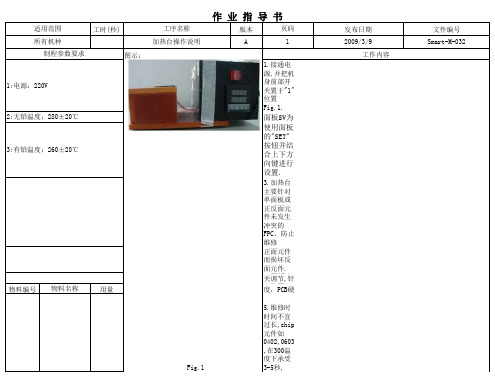
1:电源:220V
2:无铅温度:280±20℃
3:有铅温度:260±20℃Biblioteka 物料编号 物料名称用量
作业指导书
版本
页码
A
1
1.接通电 源,并把机 身前部开 关置于"1" 位置 F2i.g加.1热. 台 面板SV为 使用面板 的"SET" 按钮并结 合上下方 向键进行 设置.
核准:
3.加热台 主要针对 单面板或 正反面元 件未发生 冲突的 FPC,防止 维修
正面元件 而损坏反 面 4.温元度件开. 关 维调 修节 温,针 度,PCB硬
Fig.1
5.维修时 时间不宜 过长,chip 元件如 0402,0603 ,在300温 度下承受 3-5秒,
发布日期 2009/3/9
工作内容
文件编号 Smart-M-032
工具、设备、辅料名称 用量
连接 器,BGA等 在300度温 度下承受 5-8秒.
6.维修时 FPCA置于 加热装置 的上面, 用镊子按 住元件和 FPCA防止 其滑动.
7.维修正 面元件 时,注意 背面元件 的保护, 防止温度 过高而烫 伤反面
元件(正反 面元件较 远之产 品).
8.加热台 应定期进 行校验, 检验其温 度的准确 性.
9.加热台 使用时如 有异常或 其它功能 不良时, 请立即知 会加热台 维护人
1台 加热台
制程特性 1.重要点:客户要求的管制 点
拟定:
符号 *
审核:
Fig.3
员进行检 修,切忌私 自拆开.
注意事项 1:同一元件焊接不能超过三次,否则予以更换。 2:焊接元件时,为了避免烫伤元件,应当保持适当的距离。 3:操作过程中切勿敲打或撞击加热装置,以免将工具损坏。 4:GT产品禁止用加热台维修,一律用热风枪维修。 5: 正反面元件距离较近之产品不适宜使用加热台维修.
数显恒温水浴锅操作指导书
数显恒温水浴锅操作指导书一、引言数显恒温水浴锅是一种常用的实验室仪器,用于加热和恒温溶液或样品。
本操作指导书旨在帮助用户正确操作数显恒温水浴锅,以确保实验的顺利进行。
二、安全注意事项1. 在操作前,确保电源线接地良好,以避免触电事故。
2. 使用数显恒温水浴锅时,应远离易燃物品,并保持周围环境通风良好。
3. 操作过程中应佩戴防护眼镜和实验室防护手套,以防溅洒物伤害。
4. 在加热过程中,不要将手伸入水浴锅内,以免烫伤。
三、准备工作1. 将数显恒温水浴锅放置在平稳的台面上,并确保周围环境干燥。
2. 检查水浴锅内是否有足够的清水,确保水位高度不低于仪器要求。
3. 将电源线插入电源插座,但不要立即通电。
四、操作步骤1. 打开数显恒温水浴锅的电源开关,待仪器自检完成后,显示屏上会显示当前的温度设置。
2. 使用操作面板上的调温按钮,将所需的温度设定值输入,并按下确认键。
3. 数显恒温水浴锅会开始加热,并显示当前的实际温度。
等待数显温度达到设定值后,即可进行下一步操作。
4. 将需要加热的试管、烧瓶等容器放入水浴锅中,确保容器与水浴锅的底部有一定距离,以避免直接接触。
5. 完成实验后,关闭数显恒温水浴锅的电源开关,待仪器冷却至室温后再进行清洁和维护。
五、注意事项1. 在操作过程中,定期检查数显恒温水浴锅的温度显示是否准确,如有异常应及时联系维修人员。
2. 避免在水浴锅内加热易燃、易爆物品,以防发生安全事故。
3. 使用过程中,不要将容器内的液体溅到仪器表面,以免损坏仪器。
4. 在清洁和维护数显恒温水浴锅时,务必先断开电源,并使用柔软的布擦拭仪器表面。
六、常见问题解答1. 问:数显恒温水浴锅显示屏上出现"E1"错误代码,是什么意思?答:E1错误代码表示传感器故障,请联系专业维修人员进行检修。
2. 问:如何调整数显恒温水浴锅的温度?答:使用操作面板上的调温按钮,输入所需的温度设定值,并按下确认键即可。
加热台作业指导书
二、
操作12345三、注意事项
加热台作业指导书 1.使用中注意身体不能直接接触到加热台加热区域,否则将会造成烫伤。
2.维修无补强FPC 时,应用棉签压FPC ,避免造成FPC 压点。
3.对作业过程中随时保持加热台表面干净。
XX 电子科技有限公司
关闭电源加热台不使用时,将加热台表面清洁干净,关闭加热台电源。
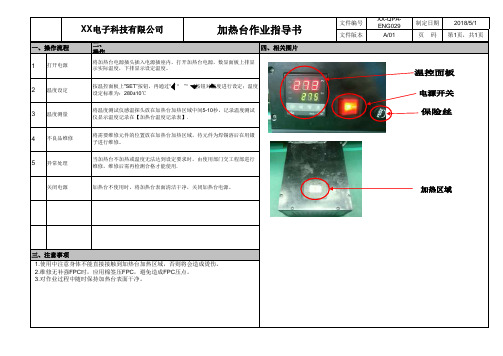
温度测量将温度测试仪感温探头放在加热台加热区域中间5-10秒,记录温度测试仪显示温度记录在【加热台温度记录表】.
不良品维修将需要维修元件的位置放在加热台加热区域,待元件为焊锡溶后在用镊子进行维修。
异常处理
当加热台不加热或温度无法达到设定要求时,由使用部门交工程部进行维修,维修后需再检测合格才能使用.一、操作流程四、相关图片打开电源将加热台电源插头插入电源插座内,打开加热台电源,数显面板上排显
示实际温度,下排显示设定温度。
温度设定按温控面板上"SET”按钮,再通过“ ” “ ”“ ”按钮对温度进行设定;温度设定标准为:280±10℃
文件编号XX-QPA-ENG029制定日期2018/5/1文件版本A/01页 码第1页,共1页。
恒温加热板使用方法
恒温加热板使用方法恒温加热板是一种基础实验仪器,广泛应用于化学、生命科学、材料科学等领域。
它具有恒温、均匀加热、温度可控等优点。
本文将从准备工作、操作步骤、使用注意事项等方面详细介绍恒温加热板的使用方法,供操作人员参考。
一、准备工作1.检查仪器是否完好,未损坏、漏电等情况。
2.准备好待加热的物料。
3.选择合适的烧杯、烧瓶或其他容器。
4.电源接好,保证电源稳定。
二、操作步骤1. 将恒温加热板放在平稳的桌面上,保证仪器稳定。
并根据实验要求选择合适的加热器大小。
2. 将加热器调节至恒温状态,根据实验要求设定加热板的温度。
大部分恒温加热板有温度显示,如需改变温度靠温度控制旋钮实现。
3. 将待加热的容器放在加热板上,并调整容器在加热板上的位置,以确保容器与加热板表面接触紧密,加热均匀。
4. 开始加热。
在加热过程中,可根据需求调整加热板的温度控制旋钮,以维持所需温度。
当目标温度达到时,可继续维持恒温的状态,直到实验结束。
5. 实验结束后,关闭加热器电源。
待仪器冷却至温度平稳后,将容器从加热板中取下,注意不能直接用手触摸,避免烫伤。
三、使用注意事项1. 恒温加热板是电器设备,使用时一定要注意安全。
操作人员应具备基本电气知识。
2. 恒温加热板应放在平稳的桌面上,且避免操作时碰撞移动,确保仪器稳定。
3. 加热前应检查加热器表面是否平整,以确保容器与加热板表面接触紧密,加热均匀。
4. 在加热过程中,应经常检查加热器表面是否干燥,如有水珠等湿气需要及时清除,以免影响加热效果,甚至造成电器故障。
5. 使用恒温加热板时,不应将温度调至太高,避免容器发生炸裂等事故,切记注意安全。
6. 加热结束后,应关闭电源,待仪器冷却至温度平稳后再取下容器,避免烫伤。
恒温加热板是一种广泛应用的实验仪器,操作过程中应注意安全、稳定和加热均匀等方面问题。
合理选择加热器大小,合理控制加热时间和温度,也是保证实验成功的重要因素。
恒温控制器用户指南说明书

Step 30. Select the Deadband Value Submenu Press d . The display will show 020.0, otherwisepress b or c.Press d to store and advance to next menu item.Step 31. Enter the Alarm 2 MenuThe display will show ALR2the top menu for Alarm 2.Repeat steps from 29 and 30 to set for Alarm 2 the same conditions as for Alarm 1.Step 32. Configuration of Display Color Selection Press a until the COLR Display Color Selection Menu appears on the Display. Configure COLR as N.CLR /GRN (green), 1.CLR / RED (red), 2.CLR /AMBR (amber). Please refer to the operator’s manual if needed.For color change on Setpoints refer to Owners Manual Section 2.Step 33. Run a TestPress a until reset the controller and return to RUN Mode to display 075.0(Ambient Temperature). Now you are ready to observe temperature as it rises 10°F higher thandisplayed. Touch the tip of the Thermocouple to raise the temperature above the Alarm 2 High value 082.0, and AL2will turn on, and Display Color will change from Green to Amber. Continue touching the tip to raise the temperature above the Alarm 1 High value 087.0and Display Color will change from Amber to Red. Annunciator “1” is turning on and off displaying output 1.Step 11. Enter to the Thermocouple Type Input Submenu Press d to display flashing, previously selected Thermocouple type.Step 12. Scroll through available selection of TC types Press b to sequence thru flashing Thermocouple types,(select k -for type "K" CHROMEGA ®/ALOMEGA ®)J K T E N DIN J R S B C - TC types J k t E N dN J R S b C - DisplayStep 13. Store TC typeAfter you have selected the Thermocouple type press d to store your selection, the instrument automatically advances to the next menu item.Step 14. Enter to Reading Configuration MenuThe display shows RDG Reading Configuration, which is the top menu for 4 submenus: Decimal Point, Degree Units,Filter Constant and Input/Reading Submenus.Step 15. Enter to Decimal Point Submenu Press d to show DEC Decimal Point.Step 16. Display the Decimal Point positionPress d again to display the flashing Decimal Point position.Step 17. Select the Decimal Point position Press b to select FFF.F Decimal Point position.Step 18. Store selected Decimal Point positionBy pressing d momentarily the Decimal Point position will be stored and the instrument will go to the next menu item.Step 19. Enter to Temperature Unit Submenu Display shows TEMP Temperature Unit.Step 20. Display available Temperature Units Press d to display the flashing Degree °F or °C .Step 21. Scroll through Temperature Units selection Press b to select °F Degree.Step 22. Store the Temperature UnitPress d to display momentarily that the Degree Unit has been stored and the instrument will go automatically to the next menu item.Step 23. Enter the Filter Constant Submenu Display shows FLTR Filter Constant Submenu.Step 24. Display the Filter Constant Value Submenu Press d to display the flashing, previously selected Filter Constant.Step 25. Scroll through available Filter Constants Press b to sequence thru Filter Constants 0001, 0002,0004, 0008, 0016, 0032, 0064and 0128.Step 26. Store the Filter ConstantPress d momentarily to store 0004Filter Constant and the instrument will automatically go to the next menu item.Step 27. Enter Alarm 1 MenuPress a until the ALR1Alarm 1 Menu appears on the Display. In the following steps we are going to DisableLatch, Active Above, Deadband 020.0, and above Setpoint 1Value will activate Alarm 1.Step 28. Select Latch Type SubmenuPress d to display flashing DSBL / ENBL .If flashing DSBL is displayed, press a , if ENBL is displayed, press b until DSBL is displayed, then press d to store and go to the next menu item.Step 29. Select the Above Type of Active Submenu Press d . If flashing ABoV Above is displayed, press a ,otherwise press b until ABoV is displayed. Press d to store and advance to next menu item.MQS3716-SM/0305WARNING:These products are not designed for use in, and should not be used for, patient-connected applications.It is the policy of OMEGA to comply with all worldwide safety and EMC/EMI regulations that apply. OMEGA is constantly pursuing certification of its products to the European New Approach Directives. OMEGA will add the mark to every appropriate device upon certification.The information contained in this document is believed to be correct, but OMEGA Engineering, Inc. accepts no liability for any errors it contains, and reserves the right to alter specifications without notice.TRADEMARK NOTICE:®,®,, andare Trademarks ofOMEGA ENGINEERING, INC.®SPECIFICATIONAccuracy:+0.5°C temp;0.03% rdg. process typical Resolution:1°/0.1°; 10 µV process Temperature Stability:0.04°C/°C RTD;0.05°C/°C TC @ 25°C (77°F); 50 ppm/°C process Display:4-digit, 7-segment LED, 57.2 mm (2.25") with red, green, and amber programmable colors for process variable, set point and temperature units.Input Types:Thermocouple, RTD, Analog Voltage and Current TC: (ITS 90)J, K, T, E, R, S, B, C, N, L RTD: (ITS 68)100/500/1000 ohm Pt sensor2-, 3-, or 4-wire; 0.00385 or 0.00392 curve Voltage:0 to 100 mV, 0 to 1 V, 0 to 10 Vdc Current:0 to 20 mA (4 to 20 mA)Output 1†:Relay 250 Vac @ 3 A Resistive Load,SSR, Pulse, Analog Voltage and Current Output 2†:Relay 250 Vac @ 3 A Resistive Load,SSR, Pulse†Only for AlarmsOptions:Communication RS-232 / RS-485 or Excitation:24 Vdc Power:100-240 Vac ±10%,50-60 Hz, 22.5 W Dimensions:289 L x 137 W x 73 D mm(11.75” L x 5.375” W x 2.875” D)Panel Cutout:279.4 L x 116.8 W mm (11.00” L x 4.60” W)Weight:1,360 g (3 lbs)Approvals:per EN 61010-1:2001iLD24 Big Displayhis Quick Start Reference provides information on setting up your instrument for basic operation. The latest complete Communication and Operational Manual as well as free Software and ActiveX Controls are available at or on the CD-ROM enclosed with your shipment .SAFETY CONSIDERATIONThe instrument is a panel mount device protected in accordance with EN 61010-1:2001, electrical safetyrequirements for electrical equipment for measurement, control and laboratory.Remember that the unit has no power-on switch. Building installation should include a switch or circuit-breaker that must be compliant to IEC 947-1 and 947-3.SAFETY:•Do not exceed voltage rating on the label located on the back of the instrument housing.•Always disconnect power before changing signal and power connections.•Do not use this instrument on a work bench without its case for safety reasons.•Do not operate this instrument in flammable or explosive atmospheres.EMC:•Whenever EMC is an issue, always use shielded cables. •Never run signal and power wires in the same conduit.•Use signal wire connections with twisted-pair cables.•Install Ferrite Bead(s) on signal wire close to the instrument if EMC problems persist.。
温控器使用说明书
一周编程电子智能室内温控器LOGIC 578001使用指南引言感谢您选择了我们的产品及对我们的信任与支持。
本装置是电子式定时恒温器,可设置一星期为周期的运行程序。
通过该装置,可对安装环境内的温度进行十分精确的调节控制,满足用户对创造一个舒适生活环境的要求。
符合标准:符合欧盟法令:EN 60730-1 标准及其修订内容欧盟 B.T.73/23/EEC号法令EN 60730-2-7 标准欧盟 E.M.C.89/336/EEC号法令及93/68/EEC修改法令EN 60730-2-9 标准产品规格:电源:二节LR6型1.5V碱性电池温度调节范围:10至35℃显示屏显示之环境温度:0至40℃(分辩率0.1℃)温度修正频率:每分钟一次微分:0.2至0.4K探针传感器:NTC3%保护等级:IP20绝缘等级:热梯度:1K/15分输出:转换继电器触点容量:8(2.5)A250V~作用类型:1BU绝缘条件:正常环境最大工作温度:50℃储存温度:0-60℃防冻温度:6℃恒定运行程序:以一星期为周期设置软件等级:A液晶显示屏夏季/冬季(采暖/空调)切换程序设置中的最小增减允许时间:1小时安装:壁式安装安装及连接:安全预防措施在进行定时恒温器的连接之前,请确认受其控制的设备系统(采暖锅炉、泵和空调系统等)电源已断开,并需检查这些设备的使用电压是否与定时恒温器底座上表明的电压相符(最大250V~).(图4)安装位置定时恒温器须安装在远离热源(暖气装置、阳光、厨房)和门窗之处,安装高度离地面约1.5米。
(图5)安装见图6-7-8电气连接将受定时恒温器控制的设备系统电线与定时恒温器的1号及2号接线柱连接见接线图10所示U=受定时恒温器控制的设备1=共用接线柱2=常开接线柱3=常闭接线柱重要事项:请务必严格遵照相关现行法律的规定及安全规范安装定时恒温器。
电池更换:当在显示屏上闪烁显示“”标志时,定时恒温器还可正常工作约一个月左右,然后将会停止工作并固定显示“”。
加热器使用说明范文
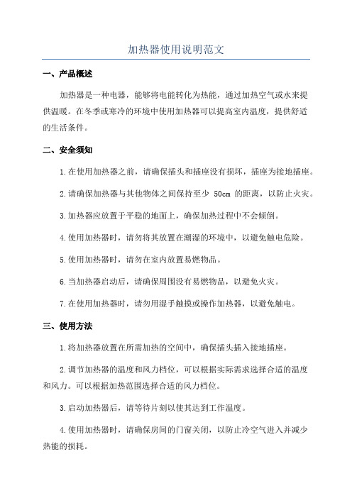
加热器使用说明范文一、产品概述加热器是一种电器,能够将电能转化为热能,通过加热空气或水来提供温暖。
在冬季或寒冷的环境中使用加热器可以提高室内温度,提供舒适的生活条件。
二、安全须知1.在使用加热器之前,请确保插头和插座没有损坏,插座为接地插座。
2.请确保加热器与其他物体之间保持至少50cm的距离,以防止火灾。
3.加热器应放置于平稳的地面上,确保加热过程中不会倾倒。
4.使用加热器时,请勿将其放置在潮湿的环境中,以避免触电危险。
5.使用加热器时,请勿在室内放置易燃物品。
6.当加热器启动后,请确保周围没有易燃物品,以避免火灾。
7.在使用加热器时,请勿用湿手触摸或操作加热器,以避免触电。
三、使用方法1.将加热器放置在所需加热的空间中,确保插头插入接地插座。
2.调节加热器的温度和风力档位,可以根据实际需求选择合适的温度和风力。
可以根据加热范围选择合适的风力档位。
3.启动加热器后,请等待片刻以使其达到工作温度。
4.使用加热器时,请确保房间的门窗关闭,以防止冷空气进入并减少热能的损耗。
5.当不再需要加热时,请关闭加热器并将插头拔出插座。
四、维护和保养1.在加热器使用之前,请确保清洁加热器外壳和进风口。
积灰和尘埃会影响加热效果并增加火灾的风险。
2.请定期清洁加热器的过滤网,以确保空气通畅且不受阻塞。
3.使用时请避免在加热器上放置物体,以免影响散热和加热效果。
五、故障处理1.加热器无法启动:请检查插头是否插入接地插座,并确保电源正常。
2.加热器发出异常响声:请检查加热器是否处于平稳的位置,并确保没有物体卡在加热器内部。
3.加热效果不佳:请检查加热器的过滤网是否需要清洁,并确保空气通畅。
六、注意事项1.请勿将加热器使用于婴儿房间或者由婴儿独自使用的地方。
2.请勿在加热器上晾晒湿衣物,以免触电或导致火灾。
3.请勿在加热器附近使用可燃气体或者易燃喷雾剂。
4.请勿私自拆卸加热器进行清洁,以免触电或者损坏设备。
5.请勿将加热器放置在进风口朝墙的位置,避免影响加热效果。
- 1、下载文档前请自行甄别文档内容的完整性,平台不提供额外的编辑、内容补充、找答案等附加服务。
- 2、"仅部分预览"的文档,不可在线预览部分如存在完整性等问题,可反馈申请退款(可完整预览的文档不适用该条件!)。
- 3、如文档侵犯您的权益,请联系客服反馈,我们会尽快为您处理(人工客服工作时间:9:00-18:30)。
恒温加热台使用说明
一,产品特性:
1.采用原装宇电PID人工智能数显温度控制仪,精度高,操作安全简单明确方便;
2.采用原装高品质宇电固态SSR)继电器,寿命是普通触点式继电器的100倍;
3.采用多根高品质纯金属发热管,维修方便快捷,故障率低;
4.整个面板采用纯铝材料制作,具有导热系数高加热快,受热均匀等特点;
5.炉体外壳全部为进口SUS304不锈钢材料制作,非特殊环境下使用决不存在掉漆生锈等弊端;
二,技术规格:
电源:220V (50HZ);控制温度范围:常温—350℃;中温型:常温-400℃;高温型:常温-450℃;产品类别:分体/连体/护栏型;表面控温精度:正负1℃
型号发热板规格功率净重SET1010 100x100x20mm士1 400W(MAX) 4.0Kg
SET2015 200X150X20MM士1 700W(MAX)5.5kg(翻盖型) SET2020 200x200x20mm士1 800W(MAX) 5.2Kg
SET3020 300x200x20mm士1 1200W(MAX) 6.5Kg
SET3030 300x300x20mm士1 1400W(MAX) 7.0Kg
SET3625 360x250x20mm士1 1500W(MAX) 8.5Kg
SET4030 400x300x20mm士1 1900W(MAX) 12.5Kg
SET5035 500x350x20mm士1 2600W(MAX) 21.3Kg
SET6040 600x400x20mm士1 3500W(MAX) 22.5Kg
SET8040 800x400x20mm士1 3800W(MAX) 26.5Kg
三,应用范围:
1、任何电子行业封胶、点胶恒温加热。
2、LED行业铝基板焊接,维修。
3、模具厂模蕊预热。
4、工业各行业恒温加热样品的烘焙、干燥和作其他温度试验,是生物、遗传、医药卫生、环保、生化实验室、分析室、教学研究的必备的工具。
四,使用方法:
1、接通电源,打开“电源开关”此时绿色“电源指示灯”常亮,表明设备已供电。
2、打开“升温开关”设备开始运行,红色“升温指示灯”常亮表明表面工作台正在持续升温;闪烁表明进入恒温状态,此时表面工作台为间断性升温。
3、使用完后,先关闭“升温开关”此时设备升温部分停止运行,此时绿色“电源指示灯”依然常亮,可以间接性警示设备依然在工作,请勿触碰工作面板。
待表面工作面板彻底冷却后(建议1小时)再关闭“电源开关”。
五,注意事项:
1.电源电压为220VAC,并且要有接地线的三孔插座和漏电开关。
2.非专业人士请勿打开机壳,或擅自改动内部接线。
3、不可用手直接接触发热板,以免烫伤。
4、长期不用或外出时,请切断电源。
5、此设备有风冷散热装置,切勿堵塞设备侧面进风口。
6、当需要更换保险管时,请一定拔下电源插头后再进行更换,以免发生触电危险。
六,控制面板说明:
,参数设置:
2,设置给定值:在基本显示状态下可以通过按∧,∨,<键来修改下显示窗口显示的设定温度控制值,按∨键减少数据,按∧键增加数据,可修改数值位的小数点同时闪动(如同光标)。
长按并保持不放可以快速地增加/减少数值,并且速度会随小数点右移自动加快(2级速度)。
而按<键则可直接移动修改数据的位置(光标),按∧或∨键可修改闪动位置的数值,操作快捷。
3,自整定(AT)操作,采用AI人工智能PID方式进行控制时,可进行自整定(AT)操作来确定PID调节参数。
在基本显示状态下按<键并保持2秒钟,将出现AT参数。
按∧键将下显示窗的OFF修改成ON,再按“O”键确认即可开始执行自整定功能。
此时仪表下显示窗将闪动显示AT字样,经过2个振荡周期后,仪表内部微处理器可自动演算出适合当前环境下的PID参数并自动结束自整定。
如果要提前放弃自整定可再按<键并保持约2秒钟调出AT参数,并将ON设置为OFF再按“O”键确认即可。
(注:系统在不同给定值下整定得出的参数值不完全相同,执行自整定功能前应先将给定值SV 设置在最常用的值上,自整定过程中禁止修改SV值。
自整定刚结束时控制效果可能还不是最佳,由于有学习功能,因此使用一段时间后方可获得最佳效果。
还可承接各种非标规格订制,非标定制交货周期为5~7个工作日。
八,保修
1,在正常使用时而非人为损坏的情况下整机享有12个月保修期(发热管保修6个月);
2,超过保修期后整机终身提供有偿服务;
注意事项:
1,电源线插到设备背部插孔内一定要检查是否有插牢固,不能出现虚接现象,要不会出现打火烧坏电源插座现象。
2,刚开机加热温度可能超过用户设置温度3-5度,数分钟过后温度下降到设置温度,本特性能提高加热台温度均匀性。
3,由于发热板为机加工产品,螺丝孔内有残余的机油,经过高温会蒸发,会冒出白色烟雾及异味,此现象属正常现象。
经过一段时间的使用此现象将消失。
4,设备使用时会发出脆响,系发热管热胀冷缩与安装孔壁及压板摩擦所致,请放心使用,不会存在危险。
5,设备本身已装置有2个保险管,保障措施安全。
请放心使用!
6,设备出厂时已经过24小时老化测试,请勿擅自更改内部参数设置,如人为修改参数错误而导致设备及人员损伤,本公司概不负责!!!。