Skyline Terraexplorer Pro系统操作手册(中文)
三维地理信息系统软件平台-Skyline软件

Skylinesoft公司的TerraSuite - 3D World Gateway基于网络的三维空间数据交互式可视化解决方案北京时空信步科技有限公司Skyline TerraSuite软件是利用航空影像、卫星数据、数字高程模型和其它的2D或3D信息源,包括GIS数据集层等创建的一个交互式环境。
它能够允许用户快速的融合数据、更新数据库,并且有效地支持大型数据库和实时信息流通讯技术,此系统还能够快速和实时地展现给用户3D地理空间影像。
1.作业流程本地作业流程:网络作业流程:2.软件介绍2.1TerraExplorer ProTerraExplorer Pro支持以客户自己的影像数据构建数字化世界。
它实现对TerraBuilder创建的地理配准三维模型的编辑和注记,用户可将地形地貌经验内容充实到模型中,以增加本地地貌特征内容。
在3D地球模型上叠加本地地貌信息,创建交互式应用系统,以区域的独特视角展现区域地貌特征、视域、地物间关系等。
TerraExplorer Pro系列所有产品采用完全相同的技术,TerraExplorer Viewer提供的三维视窗操作功能,TerraExplorer Pro GIS Edition增加了编辑、分析和控制工具,TerraDeveloper增加了用户界面客户化定制、以及访问TerraExplorer Run time Pro的功能。
TerraExplorer Pro系列产品包含丰富的工具集和扩展组件。
所有利用TerraExplorer API开发的工具都可以在TerraExplorer Pro、TerraExplorer Run Time Pro环境中运行,有专门许可的情况下可以在TerraExplorer Viewer中运行。
TerraExplorer Pro包含TerraExplorer Viewer中所有的实时3D地形可视化功能,同时包括编辑和注记由TereaBuilder产品创建的地形模型的工具。
Terra Explorer Pro操作流程
Terra Explorer Pro使用培训流程首先:介绍公司、软件性质(网络三维GIS系统)一、演示一个国外的DEMO,可以用san francisco(城市规划系统)1、打开界面,做软件总体介绍,这是一个网络三维GIS软件。
然后说明灵活的交互式漫游,介绍支持地理坐标和海拔,等等流程:双击Terra Explorer Pro桌面菜单进入系统按鼠标中键漫游地球Flight panel按钮,介绍地理坐标、海拔等等信息。
2、飞行进入DEMO系统,按路径漫游和手动漫游。
目标地物自动飞行定位流程:输入san francisco,点击fly to飞入城市选择city tour进行城市漫游,点击Coit tower进行目标物查看把漫游状态设置成rotate mode,按左键进行该建筑物旋转浏览。
3、演示方便灵活的建模功能,要详细流程:选择一个清晰的房屋影像点击3D objects ,building 按下左键沿影像上的屋檐描出轨迹(红线),右键结束(弹出绿线),此时把绿线拉到投影的根部,按下左键结束操作,立起房子选择selected face按钮,选择all walls 选择face fill tape按钮,选择image the texture 选择face texture file在C:\Program Files\Skyline\TerraExplorer Pro\Tools\Data-Library\Buildings-Textures 目录下选择一个纹理调节face scale X,Y,设置楼层4、动态物体飞行设置(飞机、汽车)流程:打开dynamic objects,点击飞机点击file name,选择一个3D飞机文件,目录C:\Program Files\Skyline\TerraExplorer Pro\Tools\Data-Library\3D-Objects\AirPlanes 在图上点击飞行路径(右键结束)设置飞行高度(altitude),飞行数度(speed),关闭对话框信息树中点取飞机,查看飞机飞行点击 view,调整观看角度,查看飞行姿态5、然后演示分析量测功能,包括等高线、剖面、通视分析、最佳路径分析、视域分析、空间分析等等。
练习手册 TerraExplore r Pro V6.5
2
加载和配置一个多边形特征图层 .................................................................. 24 高级步骤: 加载和配置一个折线特征图层: ...................................................... 26 练习 4 –执行图层特征操作 ................................................ 27 练习 4 的主题 ........................................................................................ 27 通过属性表工具查询要素 .......................................................................... 27 执行空间查询 –找到钻石头火山口一公里半径内的所有的公园 .............................. 28 编辑特征图层 –修剪(Clipping) ............................................................... 29 编辑特征图层 – 相交 (从任意两个多边形的普通区域创建一个新的要素) ................ 32 编辑特征图层– 合并 (合并同一图层的多个要素成一个多部分要素) ....................... 34 编辑特征图层 – 分解 (分拆一个多部分要素为它的各组件)................................. 34 重载图层 .............................................................................................. 35 练习 5 – 分析和工具 ..................................................... 35 练习 5 的主题 ....................................................................................... 35 测量水平距离,高差和面积 ........................................................................ 36 测量空间距离 (点之间真实的距离),高差和坡度 ............................................. 37 测量高差 .............................................................................................. 38 测量地形面积和周长 ................................................................................ 38 测量 3D 面积......................................................................................... 39 创建一张等高线地图 ................................................................................ 41 创建一张坡度地图 ................................................................................... 42 创建一个视域分析和威胁区域 ..................................................................... 43 使用绘图工具 ........................................................................................ 44 使用管线工具 ........................................................................................ 45 创建一个分辨率金字塔 ............................................................................. 46 练习 6–创建演示工具和发布工程 ........................................... 48 练习 6 的主题 ........................................................................................ 48 打开演示工具选项卡 ................................................................................ 48 通过三种方法添加兴趣点 .......................................................................... 48 播放你的演示工具 ................................................................................... 49
Skyline各个模块的软硬件运行环境说明
Skyline各个模块的软硬件运行环境说明TerraExplorer Pro:操作系统:TerraExplorer Pro可在以下任何系统中运行:Windows 98、Windows 2000、Windows Me、Windows XP或Windows Vista。
浏览器:TerraExplorer Pro 需要IE6及以上版本的网络浏览器。
处理器:可在任何Intel或与Intel兼容的处理器上运行。
推荐使用Pentium 3及以上的处理器来运行该应用程序。
内存(RAM):为了得到最佳显示效果,电脑要配备1 GB的内存。
但是,TerraExplorer Pro 也可以在配置为512MB的内存的机器下运行。
显卡:TerraExplorer Pro 支持64MB显存的显卡,推荐使用128MB或更高显存的显卡。
网络连接:为了得到最佳性能,推荐使用宽带连接。
TerraBuilder:操作系统:Windows® 2000或XP。
浏览器:Internet Explorer 5及以上版本。
处理器:可在任何Intel或与Intel兼容的处理器上运行。
推荐使用Pentium 4及以上的处理器来运行该应用程序。
内存(RAM):为了得到最佳显示效果,至少要配备512MB的内存。
但是,TerraExplorer Pro 也可以在配置为256MB内存的机器下运行。
显卡:支持16MB显存的显卡,但推荐使用128MB或更高显存的显卡。
用户权限:必须是以管理员权限的用户账户进行安装,否则会在使用中遇到问题。
仅安装过程需要管理员权限,正常使用时不需要。
TerraGate:操作系统:Windows Server 2003/Windows Server 2008/Windows XP。
处理器:推荐为多核、多线程处理器。
内存(RAM):1GB以上(视并发数量大小而定,每增加一个访问量内存增加2MB)。
用户权限:必须是管理员权限进行安装和使用。
Terra Explorer Pro操作流程

Terra Explorer Pro使用培训流程首先:介绍公司、软件性质(网络三维GIS系统)一、演示一个国外的DEMO,可以用san francisco(城市规划系统)1、打开界面,做软件总体介绍,这是一个网络三维GIS软件。
然后说明灵活的交互式漫游,介绍支持地理坐标和海拔,等等流程:双击Terra Explorer Pro桌面菜单进入系统按鼠标中键漫游地球Flight panel按钮,介绍地理坐标、海拔等等信息。
2、飞行进入DEMO系统,按路径漫游和手动漫游。
目标地物自动飞行定位流程:输入san francisco,点击fly to飞入城市选择city tour进行城市漫游,点击Coit tower进行目标物查看把漫游状态设置成rotate mode,按左键进行该建筑物旋转浏览。
3、演示方便灵活的建模功能,要详细流程:选择一个清晰的房屋影像点击3D objects ,building 按下左键沿影像上的屋檐描出轨迹(红线),右键结束(弹出绿线),此时把绿线拉到投影的根部,按下左键结束操作,立起房子选择selected face按钮,选择all walls 选择face fill tape按钮,选择image the texture 选择face texture file在C:\Program Files\Skyline\TerraExplorer Pro\Tools\Data-Library\Buildings-Textures 目录下选择一个纹理调节face scale X,Y,设置楼层4、动态物体飞行设置(飞机、汽车)流程:打开dynamic objects,点击飞机点击file name,选择一个3D飞机文件,目录C:\Program Files\Skyline\TerraExplorer Pro\Tools\Data-Library\3D-Objects\AirPlanes 在图上点击飞行路径(右键结束)设置飞行高度(altitude),飞行数度(speed),关闭对话框信息树中点取飞机,查看飞机飞行点击 view,调整观看角度,查看飞行姿态5、然后演示分析量测功能,包括等高线、剖面、通视分析、最佳路径分析、视域分析、空间分析等等。
天际线(skyline)三维地理信息平台软件
天际线(skyline)三维地理信息平台软件天际线(skyline)三维地理信息平台软件一、技术参数1、工程制作开发工具TerraExplorer Pro 版本:v6.5推荐硬件配置:操作系统 Windows XP/Vista/7/8/2003 Sever/2008 Sever处理器奔腾双核或等效配置,TerraBuilder在多核处理器环境运行最佳,并且可以利用多CPU 和多线程处理器系统内存 1GB的RAM(推荐使用8GB或更多)显卡 256MB的显卡内存(推荐使用1024MB或更高),只是在3D视图需要用户权限在安装和配置过程中需要使用管理员权限浏览器 IE 7 或更高技术指标:1. 在任何网络上都能够以流方式传输地形和叠加数据层2. 提供创建和发布丰富的三维地形可视化的所有工具3. 支持交互式绘图工具,可以在三维地形模型中创建几何图形、用户自定义对象、建筑物、文本、位图和动画4. 能够创建和导入静态和动态的二维或三维对象、符号及地理参考的信息层5. 能够导入标准的网络或本地GIS数据层6. 将层数据以GIS标准文件格式保存输出7. 通过标准COM接口与外部、本地和WEB应用程序通讯;控制所有动态及静态对象、信息层和应用程序信息、8. 提供全套的测量及地形分析工具9. 自动导航功能可创建预定义飞行路径,并在TerraExplorer中回放 10. 用鼠标、键盘和飞行控制面板的任意组合方式控制速度、高度角及视角 11. 将事先录制的飞行路径输出为视频文件,生成AVI或一系列帧文件 12. 在三维视窗中截取快照功并输出成外部图片文件13. 为对象或特定区域创建指向网页、应用程序和数据库的属性超级链接 14. 集成文本和WEB内容信息15. 通过发布工具输出三维场景提供Intranet/Internet访问16. 增强的本地或远程用户安全性保证17. ActiveX控件,将三维场景、信息树和sidemap窗口输出为控件 18. 增加了3D通视分析功能,可以实时获取立体的、动态的分析结果 19. 增强阴影分析功能,可以实时获取阴影分析结果20. 新增历史影像对比功能21. 新增快速截图对比功能22. 新增基于Android的移动端产品23. 增加了WMTS\SQLite\SQL Server spatial和Office 2010文件格式(.xlsx, .accdb)24. 能够直接读取栅格和矢量数据的原始格式。
SkyLine系统服务器安装和布置全过程说明书
三维系统服务器安装和布置过程说明书一、安装服务器操作系统以Windows Server 2003和2008企业版32位系统为主二、安装IIS网络环境三、安装Oracle数据库安装在数据库服务器上四、安装.net Frameworks框架和开发环境安装在应用程序服务器上五、安装Skyline平台环境5.1在应用程序服务器,安装Terra Explorer Pro编辑平台目的:使应用程序服务器具有T erra Explorer Developer开发环境,应用程序可以调用SGAPI中的函数,满足应用系统的运行。
安装步骤:5.2在图形服务器上,安装Terra Gate发布平台和SFS发布平台目的:在于发布图形数据,包括三维数字地球(MPT)和各种Shape数据注意:模型数据和Fly文件都是通过IIS进行发布的,需要在IIS中的创建虚拟目录。
说明:首先安装T erra Gate Manager模块,再安装SFS(Streaming Feature Service)应用模块,因为SFS是Gate平台的一部分,可以在Gate Manager中调用SFS Admin程序。
SFS模块包含两部分,分别为SFS Administration 和SFS Cache Creator,其中Admin 应用程序主要用于发布数据,Cache Creator主要用于发布之前制作缓存数据,便于数据发布的流畅。
安装过程中,需要将License文件和安装文件Copy到同一目录下。
如图所示:在V6版本中将Gate Server和SFS整合到一个安装包中了,可直接进行安装。
SFS在安装过程中,自动会在IIS的默认网站中创建SFS的虚拟发布目录。
安装步骤:5.3在最终用户和客户端,安装Terra Explorer浏览平台(俗称View)目的:是用户可以在桌面端通过浏览器查看三维场景。
安装六、配置Oracle数据库环境和内容七、布置IIS服务环境配置IIS的网络环境,需要配置指定的IP地址,添加IIS网站支持的“启动默认内容文档”类型Default.fly,在MIME类型中添加IIS的扩展类型。
TerraExplorer+Skyline+Pro中文用户手册
TerraExplorer® Pro™中文用户手册Version 4.6.2传输数字地球北京时空信步科技有限公司北京大学城市模拟与政策分析实验室引言关于本手册本手册是Skyline公司的TerraSuite软件系列的TerraExplorer Pro的中文用户手册。
本手册介绍的软件版本是4.6.2。
阅读说明引言:简单介绍skyline的TerraSuite软件系列和本系统的功能特性。
第一章:介绍了skyline软件的TerraSuite系列,TerraExplorer Pro功能特点,运行环境及软件的安装与卸载。
第二章:介绍了TerraExplorer Pro的场景漫游操作和软件的快捷键。
第三章:详细介绍了TerraExplorer Pro菜单功能和操作编辑方法以及系统设置的选项。
对于平台用户来说,仔细阅读本章是非常必要的,对于参与三维应用设计的人来说,仔细阅读这部分会使你的工作达到事半功倍的效果。
第四章:详细介绍了TerraExplorer Pro的所有扩展模块的功能及操作。
第五章:适用于本系统的三维建模规范,详细说明了利用最少的数据量表达真实世界和精确模型的建立与导入方法。
对于需要导入美观的3ds max模型的用户来说,应该仔细阅读本章。
第六章:技术支持参考资料《TerraExplorer Pro UserManual_v4.6.2》目录引言 (2)关于本手册 (3)阅读说明 (3)参考资料 (3)第一章TerraSuite简介 (6)TerraSuite简介 (6)TerraExplorer Pro简介 (7)TerraExplorer Pro功能特点 (9)运行环境 (10)1.4.1 硬件环境 (10)1.4.2 软件环境 (10)TerraExplorer Pro的安装与卸载 (10)第二章TerraExplorer Pro基本操作 (11)系统界面简介 (11)场景漫游操作 (12)快捷键 (13)第三章TerraExplorer Pro功能介绍 (14)系统设置和选项设置 (14)3.1.1 系统设置 (14)3.1.2 选项设置 (19)信息栏窗口的编辑 (19)对象编辑 (22)3.3.1 二维对象编辑 (22)3.3.2 三维对象编辑 (23)量测分析工具 (29)动态对象编辑 (29)漫游路线设置 (30)观测位置 (31)第四章系统工具应用 (32)Find Object 和Duplicate Object (33)4.1.1 对象查找 (33)4.1.2 对象复制 (34)Free Hand Drawing (35)Create Power Line (35)MapInfo MapMaker Geocoding Client (36)Navigation Aid (37)Multi Coordinate Systems (38)Make Point Cloud Model (38)Data Library (39)Snapshot (39)第五章三维建模规范 (40)建模流程 (40)贴图纹理 (41)第六章技术支持 (41)第一章TerraExplorer Pro简介1.1TerraSuite简介Skyline TerraSuite软件是利用航空影像、卫星数据、数字高程模型和其它的2D或3D 信息源,包括GIS数据集层等创建的一个交互式环境。
skyline中文开发帮助(内部开发文档)
Skyline软件开发接口分类ITerraExplorerIPlaneIObjectManagerIInformationTreeITerrainIContainerIRenderISnapShotIStartPositionITerraExplorerEventsICoordSys_ITerraExplorerEvents5_ITerraExplorerEvents5主要功能是为ITerraExplore提供事件信息处理功能. 这个开发接口代替了以前的_ITerraExplorerEvents, _ITerraExplorerEvents2,_ITerraExplorerEvents3,_ITerraExplorerEvents4接口, 并扩展了通用事件,双击事件及HUD事件。
什么是HUD?HUD是Head UP Display的英文缩写,又译成抬头显示器(Head Up Display),以下简称HUD,是目前普遍运用在航空器上的飞行辅助仪器。
抬头的意思是指飞行员不需要低头就能够看到他需要的重要资讯。
抬头显示器最早出现在军用飞机上,降低飞行员需要低头查看仪表的频率,避免注意力中断以及丧失对状态的控制。
在skyline软件中HUD指在应用软件时基于地形视窗监视飞行状态及视角图形及文字信息辅助工具。
OnLoadFinished 这种方法在TerraExplorer在加载完成Fly文件时被调用。
OnFileClosing, 这种方法在TerraExplorer关闭Fly文件前通知客户文件关闭前被调用。
OnFrame, 这种方法获取TerraExplorer在飞行时每一个Frame的状态。
OnTerraExplorerMessage 这种方法可以得到交互式触发带有massage对象massage中的内容。
OnObjectAction这种事件当特定对象某一种状态发生变化时被触发语法: OnObjectAction([in] BSTR ObjectID,[in] int Action)ObjectID指特定对象的唯一IDAction 指动态的状态标识o AC_FLYTO = 0飞行标识o AC_CIRCLEPATTERN = 1环绕标识o AC_OVALPATTERN = 2椭圆标识o AC_LINEPATTERN = 3线状标识o AC_ARCPATTERN = 4弧状标识o AC_FOLLOWBEHIND = 5在对象的后面o AC_FOLLOWABOVE = 6在对象的上方o AC_FOLLOWBELOW = 7在对象的下面o AC_FOLLOWRIGHT = 8在对象的右边o AC_FOLLOWLEFT = 9在对象的左边o AC_FOLLOWBEHINDANDABOVE = 10在对象的后上方o AC_FOLLOWCOCKPIT = 11以座舱方式o AC_FOLLOWFROMGROUND = 12以地面的位置观看对象o AC_STOP = 13The object was stopped being played (i.e., after a fly to operation).停止操作o AC_JUMP = 14Jump to the object operation was started.跳跃至对象o AC_DELETE = 15删除对象o AC_EDIT_FINISHED = 16对象完成编辑时o AC_OBJECT_ADDED = 17对象增加到视图中o AC_PLAY = 18运行执行对象o AC_EDIT_STARTED = 20对象开始编辑时OnFileSaveTerraExplorer 在fly文件保存进,执行这个文件语法:OnFileSave()附:用户在保存fly时更新相关信息的数据库可用些事件OnRenderQualityChanged实时地反馈用户浏览更新时地形效果质量值,一般用于loading功能语法OnRenderQualityChanged([in] int Quality)参数:Quality–用户浏览时地形效果质量值. 这个参数是0到100之间以10递增的数据。
terraeplorer+skyline+pro中文用户手册
TerraExplorer® Pro™中文用户手册Version 4.6.2传输数字地球北京时空信步科技有限公司北京大学城市模拟与政策分析实验室引言关于本手册本手册是Skyline公司的TerraSuite软件系列的TerraExplorer Pro的中文用户手册。
本手册介绍的软件版本是4.6.2。
阅读说明引言:简单介绍skyline的TerraSuite软件系列和本系统的功能特性。
第一章:介绍了skyline软件的TerraSuite系列,TerraExplorer Pro功能特点,运行环境及软件的安装与卸载。
第二章:介绍了TerraExplorer Pro的场景漫游操作和软件的快捷键。
第三章:详细介绍了TerraExplorer Pro菜单功能和操作编辑方法以及系统设置的选项。
对于平台用户来说,仔细阅读本章是非常必要的,对于参与三维应用设计的人来说,仔细阅读这部分会使你的工作达到事半功倍的效果。
第四章:详细介绍了TerraExplorer Pro的所有扩展模块的功能及操作。
第五章:适用于本系统的三维建模规范,详细说明了利用最少的数据量表达真实世界和精确模型的建立与导入方法。
对于需要导入美观的3ds max模型的用户来说,应该仔细阅读本章。
第六章:技术支持参考资料《TerraExplorer Pro UserManual_v4.6.2》目录引言 (2)关于本手册 (3)阅读说明 (3)参考资料 (3)第一章 TerraSuite简介 (6)TerraSuite简介 (6)TerraExplorer Pro简介 (7)TerraExplorer Pro功能特点 (9)运行环境 (10)1.4.1 硬件环境 (10)1.4.2 软件环境 (10)TerraExplorer Pro的安装与卸载 (10)第二章 TerraExplorer Pro基本操作 (11)系统界面简介 (11)场景漫游操作 (12)快捷键 (13)第三章 TerraExplorer Pro功能介绍 (14)系统设置和选项设置 (14)3.1.1 系统设置 (14)3.1.2 选项设置 (19)信息栏窗口的编辑 (19)对象编辑 (22)3.3.1 二维对象编辑 (22)3.3.2 三维对象编辑 (23)量测分析工具 (29)动态对象编辑 (29)漫游路线设置 (30)观测位置 (31)第四章系统工具应用 (32)Find Object 和Duplicate Object (33)4.1.1 对象查找 (33)4.1.2 对象复制 (34)Free Hand Drawing (35)Create Power Line (35)MapInfo MapMaker Geocoding Client (36)Navigation Aid (37)Multi Coordinate Systems (38)Make Point Cloud Model (38)Data Library (39)Snapshot (39)第五章三维建模规范 (40)建模流程 (40)贴图纹理 (41)第六章技术支持 (41)第一章TerraExplorer Pro简介1.1TerraSuite简介Skyline TerraSuite软件是利用航空影像、卫星数据、数字高程模型和其它的2D或3D信息源,包括GIS数据集层等创建的一个交互式环境。
TerraExplorer Pro操作详细教程

TerraExplorer Pro 操作手册
Image Label Properties 图像标签属性
Appearance
Name
对象名称
Activation Actition 激活对象的方法 Line To Ground
Line Color
线的颜色
Image Options
Image File
图像文件
Line Color
线颜色
Line Opacity
线的不透明度
Line Style
线型
Line Width
线宽
Line Back Color
线背景色
Line Back Opacity 线背景不透明度
Line Pattern
线型
Line Spline
线形样条线
Position
TerraExplorer Pro 操作手册
投影
General
Show In Basic
是否显示
Message
信息
Tool Tip
标签
Default Viewing Distance 默认视距
Max. Visibility Distance 最大可视高度
Min. Visibility Distance 最小可视高度
Order Polyline Properties 线属性
Line of Sight Analysis Properties 视线分析 属性
Name
对象名称
Activation Action 激活对象的方法
Observer Position
观察者位置
X
经度
Y
纬度
Settings
Skyline Terraexplorer Pro系统操作手册中文
系统平台操作手册一、TerraExplorer Pro简介 (2)二、TerraExplorer Pro菜单 (3)1、File (3)2、Edit(第九章第二节) (4)3、View (6)4、Navigation (6)5、Layers (9)6、Creat (12)7、Measurements(第十八章) (15)8、Tools(第十九章) (16)collaboration (16)Extract terrain (16)GPS tracking (18)Duplicate Objects (18)Free hand drawing (18)Build power Aid (18)Multiple coordinate system (19)Mil-std-2525b (19)Make point cloud model (19)Data library (19)Snapshot (19)Save snapshot to file (19)Snapshot size (19)Project setting (19)Options (20)9、Help (22)三、TerraExplorer Pro工具栏(操作方法参考菜单中creat的操作方法) (23)Project: (23)measurements (23)Layer (24)2D Objects (24)3D—Objects (24)dynamic object (25)route (25)四、对象操作 (25)绑定(第九章最后一节) (25)一、TerraExplorer Pro简介TerraExplorer Pro:它是一个桌面应用程序,使得用户可以浏览分析空间数据,并可以对其进行编辑。
也可以在上面添加二维或者三维的物体、路径、场所以及地理信息文件。
TerraExplore与TerraBuilder 所创建的地形库相连接,并且可以在网络上直接加入GIS图层。
skyline软件使用
Your site here
2、Add source file:
❖ 源数据类型: 1、image 2、elevation 3、vectors
Your site here
点击next,完成数据导入工作
Your site here
创建对象- Route
1 23
❖ 1、新建路径 ❖ 2、开始播放路径 ❖ 3、停止录制 ❖ 4、路径起始位置 ❖ 5、后退
4
5
6、前进 7、路径最终位置 8、开始 9、通过点位,控制路径 10、导出AVi文件
Your site here
3、加载图层
1
2 3
4
5
❖ 1、添加适量图层 ❖ 2、添加影像 ❖ 3、添加dem ❖ 4、shape文件属性表 ❖ 5、创建金字塔文件
Your site here
4、Create mpt file
为了能够是我们的MPT文件展示效果达到最 好,我们还需要使用TerraBuilder其他高 级编辑工具。
Your site here
5、其他编辑工具栏:
Your site here
标准栏:
❖ 1、Project setting ❖ 2、Add source file ❖ 3、Convert Sources files ❖ 4、Create mpt file
形数据。
Your site here
Your site here
TerraGate
TerraExplorer Pro
软件操作
TerraBuilder
skyline TerraExplore PRO二次开发笔记
skyline TerraExplore PRO二次开发笔记1. 开发环境(B/S)本地开发环境(IIS,TEPro, TEDEV,根据项目的要求具体选择服务器端的语言和客户端的脚本语言,如:ASP,,jsp,php…..,使用的开发工具用: Microsoft Visual Studio .NET 2003/5, 客户端脚本语言:javascript/jscript,vbscript,使用的开发的工具:UltraEdit,Editplus等等,根据自己爱好)网络开发环境:在服务器上进行开发和调试,但在服务器上必须安装internet lic+TerraGate 的情况下,才能应用,本机只需安装TE即可;2. 服务器的配置服务器端必须要安装TerraGate3.0/3.5,的主要作用是进行mpt的网络发布,在TerraGate 可以设置多个mpt,供fly工程文件调用。
(调用文档)3. 客户端浏览客户端需要安装TE(TerraExplorer)+IE60版本即可使用本系统。
4. 二次开发的概述TerraExplorePro提供了一整套的API,供二次开发使用,它提供了一些访问外部信息的方法,比如:数据库或矢量数据的。
所有这些以COM协议为基础的界面都可以通过脚本语言管理,也可通过非脚本语言控制(如:C++或Visual Basic)来开发(c/s)。
TerraExplorePro也可以设置ActiveX控件。
它作为ActiveX控件通常被应用在可视化界面的3D窗口、信息树、导航图的操作。
下面主要讨论TerraExplorePRO API的功能:用户接口API:是对标准TerraExplorer Pro API的扩充。
利用其强大功能,开发人员可控制和激活大多数TerraExplorer Pro的工具和函数。
如:1 、控制飞行和视景2、对象的创建3、信息树和管理4、层和对象管理5、事件处理6、在网页和windows应用程序中添加ActiveX控件另外,TerraExplorerPro的API还允许常用的一些操作,比如控制容器中的内容,查询地形高度信息,获取快照,查找对象等更多操作。
TerraExplorer Pro v7.0用户操作手册-2019v1.0
4.1
启动界面 ......................................................................................................................... 13
4.2
界面布局 ......................................................................................................................... 13
3.1
TerraExplorer 7.0.1 版本新特性 .......................................................................................8
3.1.1 栅格图层改进 ............................................................................................................ 8
3.2.6 分析工具..................................................................................................................10
3.2.7 使用 SkylineGlobe Server– 发布工具 .....................................................................10
1.1
关于本手册 ....................................................................................................................... 1
skyline_API详细使用说明手册
</tr>
</table>
<OBJECT ID= "TE" CLASSID="CLSID:3a4f9191-65a8-11d5-85c10001023952c1"
></OBJECT>
</body>
</html> (2)Save 方法 :只能保存 fly 工程,mpt 工程不能保存 C#: objTerraExplorer = new TerraExplorerClass(); objTerraExplorer.Save();
对全部高中资料试卷电气设备,在安装过程中以及安装结束后进行高中资料试卷调整试验;通电检查所有设备高中资料电试力卷保相护互装作置用调与试相技互术关,系电,通力根1保过据护管生高线产中敷工资设艺料技高试术中卷0资不配料仅置试可技卷以术要解是求决指,吊机对顶组电层在气配进设置行备不继进规电行范保空高护载中高与资中带料资负试料荷卷试下问卷高题总中2体2资,配料而置试且时卷可,调保需控障要试各在验类最;管大对路限设习度备题内进到来行位确调。保整在机使管组其路高在敷中正设资常过料工程试况1卷中下安,与全要过,加度并强工且看作尽护下可1都关能可于地以管缩正路小常高故工中障作资高;料中对试资于卷料继连试电接卷保管破护口坏进处范行理围整高,核中或对资者定料对值试某,卷些审弯异核扁常与度高校固中对定资图盒料纸位试,置卷编.工保写况护复进层杂行防设自腐备动跨与处接装理地置,线高尤弯中其曲资要半料避径试免标卷错高调误等试高,方中要案资求,料技编试术写5、卷交重电保底要气护。设设装管备备置线4高、调动敷中电试作设资气高,技料课中并3术试、件资且中卷管中料拒包试路调试绝含验敷试卷动线方设技作槽案技术,、以术来管及避架系免等统不多启必项动要方高式案中,;资为对料解整试决套卷高启突中动然语过停文程机电中。气高因课中此件资,中料电管试力壁卷高薄电中、气资接设料口备试不进卷严行保等调护问试装题工置,作调合并试理且技利进术用行,管过要线关求敷运电设行力技高保术中护。资装线料置缆试做敷卷到设技准原术确则指灵:导活在。。分对对线于于盒调差处试动,过保当程护不中装同高置电中高压资中回料资路试料交卷试叉技卷时术调,问试应题技采,术用作是金为指属调发隔试电板人机进员一行,变隔需压开要器处在组理事在;前发同掌生一握内线图部槽纸故内资障,料时强、,电设需回备要路制进须造行同厂外时家部切出电断具源习高高题中中电资资源料料,试试线卷卷缆试切敷验除设报从完告而毕与采,相用要关高进技中行术资检资料查料试和,卷检并主测且要处了保理解护。现装场置设。备高中资料试卷布置情况与有关高中资料试卷电气系统接线等情况,然后根据规范与规程规定,制定设备调试高中资料试卷方案。
SkylineGlobe软件快速入门手册
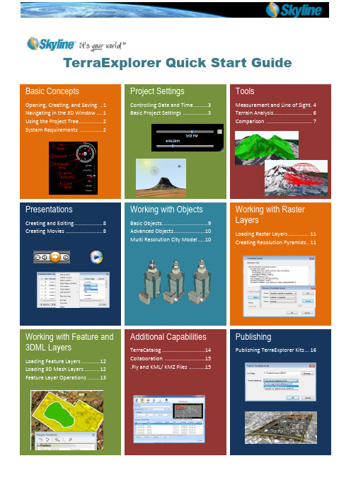
TerraExplorer Quick Start GuideBasic ConceptsOpening, Creating, and Saving .. 1Navigating in the 3D Window .... 1 Using the Project Tree . (2)System Requirements (2)Project SettingsControlling Date and Time . (3)Basic Project Settings (3)ToolsMeasurement and Line of Sight. 4 Terrain Analysis.......................... 6 Comparison . (7)PresentationsCreating and Editing ................... 8 Creating Movies . (8)Working with ObjectsBasic Objects...............................9 Advanced Objects .....................10 Multi Resolution City Model .. (10)Working with Raster LayersLoading Raster Layers .............. 11 Creating Resolution Pyramids .. 11Working with Feature and3DML LayersLoading Feature Layers ............ 12 Loading 3D Mesh Layers .......... 12 Feature Layer Operations .. (13)Additional CapabilitiesTerraCatalog .............................14 Collaboration ...........................15 .Fly and KML/ KMZ Files .. (15)PublishingPublishing TerraExplorer Kits (16)Basic ConceptsOpening, Creating, and Saving a ProjectTerraExplorer basic commands are available from the TerraExplorer button located at the upper-left corner of the application.Opening an Existing ProjectClick and then click Open > browse to an existing .Fly file. You can open a US demo project by clicking the link on the Start page.Saving a Project as a FLY FileA .Fly file is a compressed binary file that contains all the project settings and content, and pointers to terrain databases (MPT) or other loaded files. Clickand then click Save or Save As …Creating a New ProjectClick and then click New > In dialog, browse to required terrain database (MPT), and click OK > Define project settings.Navigating in the 3D WindowNavigate through the 3D World in the way you find most natural and intuitive: navigate freely using on-screen Navigation controls or any of the three mouse modes, or fly to predefined locations or objects.Viewing or Flying to a Location or Object (Using the Project Tree)1. In the Project Tree , double-click the location or object, or right-click and select Fly to , Jump to , or View . If you view the object, you can select one of the pre-defined flight patterns that compass about the object.2. To stop a flight to a location right-click in 3D Window , and select Stop or press the Spacebar .Free FlightUsing the mouse to navigate∙ Navigation tab > > click a Navigation mode to determine how the mouse controls navigation. In Drag mode , do thefollowing:∙ To pan – Click and drag the mouse to the sides, forward, or backward. ∙ To zoom in and out – Roll the middle mouse wheel.∙ To change direction and tilt – Click and drag the middle mouse wheel. Using HUD Navigation Controls:1. View tab > select Graphic HUD to display.To change plane tilt - Click and drag tilt slider. To look North - Click Northindicator.To free fly in all directions - Use blue joystick. To zoom in and out – Click and drag zoom slider. To change plane direction - Click and drag compass ring.To slide right, left, forward or back Underground Navigation1. Home tab > Underground Mode .2. Navigate in the 3D environment. You can freely go through the terrain surface in any direction.Following a Dynamic Object∙ In the Project Tree > double-click the required dynamic object.Basic Concepts—Using the Project TreeThe Project Tree provides a list of elements in the terrain that can be sorted and arranged into groups. Using this list, you control the appearance of information in the 3D Window.Showing and Hiding Objects or Layers in the 3D WindowIn Project Tree , click the object or layer’s show/ hide icon to display or hide it inthe 3D Window.Selecting a Tree ItemIn Project Tree , click the item. Double –clicking performs the item’s activation action (fly to, jump to, circle/ oval/ line pattern, etc.) that was set in its property sheet.Creating and Working with Groups1. Right-click blank area (root) of Project Tree (for subgroup, right- click parent group) > select Create Group .2. Type the name of the new group and press ENTER .3. To move an item into a new group, click and drag it onto group folder.4. To add a new element to a group,right-click group > point to New > select Location , Presentation or Message . 5. To set group properties, right click <group> > Properties . In property sheet , setparameters.Creating Locations1. In the Project Tree right-click > New > Location . Type a name for the location and click.2. Open property sheet to set activation action or add a message: in Project Tree right-click location > Properties .System RequirementsSystem requirements for installing and using TerraExplorer.∙ Operating System - Windows® XP/ Vista/ 7.∙ System Memory – 1GB of RAM (4 GB or more recommended).∙ Video Card - 128MB of video memory (512 MB or more recommended). Pixel and vertex shader v3.0 is required for dynamic water effects, animated cloud map, and sky texture. ∙ Processor – Pentium IV or equivalent.∙Internet Connection - Broadband connection (recommended). ∙ Browser - Microsoft Internet Explorer 7 or higher.Project SettingsBasic Project SettingsProject Settings, including general settings, terrain parameters, flight model, and application layout are saved in the .Fly file and applied each time this file is used.To open Settings dialog: Home tab > click Project Settings > Click required tab.Environment tab∙ Select a Sky Color and Fog Color.∙ Enter a Visual Range (largest visible distance to the horizon).∙ Select Sky texture and Clouds map to apply. Select Clouds speed and if to enable water effects.Terrain Database tab∙ Select the local or remote Terrain (MPT) Database currently used by this project.∙ Enter the Number of Terrain Imaginary (resolution) Levels that are used to enhance the visual quality when the camera is close to the ground.∙ Set the project’s Terrain Coordinate System .Date and Light tab∙ Control the sun display and the startup date and time.∙ Select the Use Sunlight check box if you want the sun to serve as the light source for the project. ∙ Select a range and Date and Time for the Startup Time Slider.General tab∙ Set basic parameters for the .Fly file, including startup message parameters.∙ Click Set as Home to set the current camera location as the default startup position for this .Fly file.∙ Click Add Message to determine the message to be shown when the project is opened. ∙ Click Wait to set the number of seconds TerraExplorer waits at the beginning of the session.Controlling Date and TimeWhen the sun is used as a project’s light source, displayed light on the terrain corresponds to the date / time selected on the Time Slider. Project data containing timespan tags displays on the terrain according to the timespan set.1. View tab > select Time Slider . The Time Slider displays in the 3D Window. Drag the blue marker and yellow arrow together to the required date and time on the slider. If you want to display data whose timespans fall anywhere in a time range, drag the blue marker to the start point of the time range and theyellow arrow to the endpoint of the time range .2. Click Date and Time Settings icon to the right of the slider to select a timezone, and time slider range. (When a one year range is selected, two sliders display, one for the date, and one for the time of day). Note :Project startup settings for the date and time can be set in the Date and Light tab in the Project Settings dialog box and are saved in the .Fly file. Any date and time settings made using the Date and Time Settingsicon are not saved to the .Fly.ToolsTerraExplorer measurement and terrain analysis tools deliver extensive topographical and strategic information, enabling a more accurate geospatial understanding of the terrain.Measurement, Line of Sight, and Shadow ToolsHorizontal/ Aerial/ Vertical Distance1. Analysis tab>Click Horizontal/ Aerial/ Vertical Distance.2. Click any point in the terrain or on an object to define the start point and other segments. Right-click to finish.Terrain Area (and Perimeter) 1. Analysis tab>Click Terrain Area.2. Click to define start point. Drag to additional points and click to define a region. Right-click to finish. > In open dialog select either: ∙ Horizontal Plane (for horizontal projection).∙ Terrain Surface (for surface area)> enter Sample interval> click Calculate .3D Plane Area and Perimeter (of a polygon on an arbitrary plane) 1. Analysis tab>Click 3D Plane Area.2. Click to define start point. Drag to additional points and click to define a region. Right-click to finish.Line of Sight - Indicates whether specific locations in the 3D World can be seen (green line) from a selected position or not (red). 1. Analysis tab>Click Line of Sight.2. In property Sheet , set parameters > In 3D Window , click to define observer viewpoint, then click additional times for targets. Right click to finish.Viewshed - Indicates which areas on the entire selected terrain are visible from the viewpoint (colored in green), and which areas cannot be viewed (red).1. Analysis tab>Click Viewshed.2. In property Sheet , set parameters > In 3D Window , click to define observer viewpoint, then click for endpoint.ToolsMeasurement, Line of Sight, and Shadow Tools – cont.3D Viewshed – Create a 3D viewshed on buildings/ models and on bare terrain. 1. Analysis tab>click 3D Viewshed .2. In 3D Window , click to define your viewpoint for the 3D viewshed, and then click again to define your desired end point.3. In property sheet , set parameters such as visible/hidden area color and viewshed Distance and FOV .Dynamic 3D Viewshed - Create a graphical representation of the view froma moving object.1. Analysis tab>click 3D Viewshed >select Dynamic 3D Viewshed .2. In dialog box, set the viewshed parameters, such as Speed and FOV.3. Select a method of designating the area for the dynamic 3D viewshed (Follow Line , Selected Group , or From Clipboard .Viewshed Query - Analyze the visibility from multiple viewshed observer viewpoints to a selected area.1. Analysis tab > click 3D Viewshed > select Viewshed Query .2. In the dialog box, set the Query parameter defining which viewsheds are taken into account, and all other parameters.3. Select a method of designating the area for the viewshed query (Follow Line , Fill Area , Selected Group , From Clipboard , or Viewshed Area ).Threat Dome - Indicates the volume visible from a given point on the terrain.1. Analysis tab > Click Threat Dome.2. In property Sheet , set parameters > In 3D Window , click to define pivot point.Selection Shadow - Display a shadow effect for selected objects. 1. Select the objects from which you want to cast a shadow. 2. Analysis tab > click Show Selection Shadow .Shadow Query - Calculate and graphically represent overall shadow coverage or a particular object’s shadow effect in a specified area. 1. Analysis tab > click Shadow Query .2. In the dialog box, set the Query parameter defining which objects’ shadows are taken into account, and all other parameters.3. Select a method of designating the area for the shadow query (Follow Line , Fill Area , Selected Group , or From Clipboard .ToolsAnalysis ToolsSlope Map - Apply palette colors according to degree of slope and slope arrows to indicate slope direction. 1. Analysis tab > click Slope Map . 2. Select Slope Colors / Slope Arrows .3. In property sheet , set parameters such as palette and coverage area,4. Click in 3D Window to add opposite corners of the coverage rectangle.Contour Map -Apply palette colors to each elevation level and connect points of equal elevation with contour lines.1. Analysis tab > click Contour Map .2. Select Contour Colors / Contour Lines .3. In property sheet , set parameters such as contour palette and coverage area.4. Click in 3D Window to add opposite corners of the coverage rectangle.Flood Tool - Calculate land covered by flooding. 1. Analysis tab > click Flood .2. In 3D Window , click center of coverage area.3. In property sheet , set single instance of water level rising or continuous and related parameters.4. Drag mouse to required radius size and click.Volume Tool - Analyze amount of terrain removed from or added to the terrain surface.1. Analysis tab > click Volume .2. Objects tab > click Modify Terrain > Draw a polygon in the 3D Window to define the terrain area for which you want to modify elevation values.3. On Analysis tab click Volume Tool. In dialog box select checkboxes of objects to analyze and click Calculate .Best Path - Calculate best path without exceeding definable climb and descent slope limits.1. Analysis tab > click Best Path .2. In property Sheet , set parameters > In 3D Window , click to define start and end point.ToolsComparison ToolsSnapshot Comparison - Create and compare snapshots showing different versions of the area in view in the 3D Window by showing or hiding objects in the Project Tree1. Navigate to required area and click Snapshot Comparison2. Show/hide objects in the Project Tree, and click Compare .3. Mode selection – Choose between four clipping modes and Transparency mode.4. Slider control – Define the clipping or transparency level extent.Imagery Comparison - C ompare 2 imagery layers or an imagery layer to the base terrain by dynamically clipping or modifying transparency of an overlaying layer. 1. Zoom in on an area with a visible imagery layer. 2. Analysis tab>Click Imagery Comparison .2. Mode selection – Choose between four clipping modes and Transparency mode.3. Slider control – Define the clipping or transparency level extent.PresentationsEasily share your 3D visualization with others by creating a multi-step presentation that can be replayed, in which you combine a customized flight route with a particular display of the project.Step 1: Create a flight route – Animate movement over the terrain by recording your navigation or by adding locationsCreating a Recorded Route1. Presentation tab> Record Flight .2. Navigate freely in the 3D Window to any location or point of interest. Adjust zoom, tilt, etc.3. Presentation tab> Stop Record . Creating a Locations Route∙ Fly to the required location, and then Presentation tab> Add Location OR∙ Presentation tab> Add Location > Select Location . Select a location from the list of project locations.1. Presentation tab> Edit Presentation .2. Add captions when required: right-click step> Add Caption .3. Use Move Up and Move Down commands to reorder steps.4. To delete a step, select it and click Delete .5. For each step, select mode for advancing the step: Continue trigger >∙ Immediate - Next step follows immediately. ∙ Click Button – Next step follows when Next command on the Ribbon is clicked.Step 4: View PresentationClick Presentation tab > Play . Use thetoolbar to start, stop, pause, rewind, and fast forward.Creating MoviesShare your 3D visualization even with people who do not have TerraExplorer installed, by creating a movie in AVI format from any presentation in your project. Your movie can then be shown using any standard AVI Viewer.1. Create a presentation.1. Presentation tab > Movie group > set frame size and number of frames per second.2. Presentation tab > Movie group >Create Movie .3. Browse to location for movie file.4. Set Video Compression properties.Working with ObjectsBasic ObjectsAdd and edit graphic entities, each with its own styling properties. Objects include: labels, lines, polygons, 2D/ 3D shapes, 3D models, and buildings. Available objects depend on TerraExplorer level. Objects can be organized in Project Tree groups.Creating an Object1. Objects tab> click <required object>.2. Click and draw the object in the 3D Window . Right-click to finish. For 2D and 3D shapes, left-click to finish.Selecting an ObjectAfter selecting a single object, a yellow frame surrounds the object and the object’s property sheet opens. When selecting multiple objects, a yellow frame surrounds each of the selected objects and the Multi Edit property sheet opens. Selecting a Single Object∙ From Project Tree : In the Project Tree , select the object > On the Home tab, click Properties . OR ∙ From 3D Window : On the Home tab, click Select> In the 3D Window , select the object.Selecting Multiple Objects∙ From Project Tree : In the Project Tree , select the required objects (Use SHIFT and CTRL to select sequential and non-sequential tree items) > On the Home tab, click Properties .∙ From 3D Window : On the Home tab, click Select > Press and hold the CTRL key > In the 3D Window , select each of the objects you want > On the Home tab, click Properties .∙ From 3D Window (all objects in a selected area): On the Home tab, click Select Area > In the 3D Window , draw the area polygon by clicking the mouse (at least three points) and right-click to finish > On the Home tab, click Properties .Editing an Object1. Project Tree > Right-click object and select Properties . On the top of the property sheet, click: ∙To edit the entire object. Then: ∙ To move object. Then drag to required location.∙To changethe object’s altitude. Then drag to required height.∙ To edit object nodes , click. Then:Note : Only polylines, 2D polygons, and 3D polygons (added in TE Plus or Pro) have object nodes.∙ to move a node. Thenclick required node and drag to new location.∙ to change node’s altitude. Then click required node and drag to new height.∙ To delete a node, point to the node, right-click, and select Delete.∙ To add a node, point to one of the object’s lines, and click anywhere a red node appears.Note : Object position and nodes can also be modified from object’s property sheet.2. Set properties such as color, altitude, timespan, tooltip, and texture in the object’s property sheet.Adding 3D Models1. Objects tab > click 3D Model .2. In dialog, browse to the required file to load.3. In 3D Window , click mouse to define position o f model’s pivot point on terrain.4. Adjust the model’s position and size in the 3D Window or from property sheet. See: “Editing an Object .”5. Using the property sheet , set the parameters of the 3D object.6. Drag any of the three arrow resizers in/ out to adjust any of the model’s dimens ions.Working with ObjectsCreate advanced objects: dynamic objects, modify terrain objects, video, buildings, and 3D models.Creating and Editing Dynamic Objects1. Objects tab> Video , 3D Objects, or Dynamic Objects group> click <required object >.2. Property sheet > File Name field > browse for a model file.3. In the property sheet, set Motion Style and other properties.4. In 3D Window , click mouse to define waypoints. Right-click to finish.5. For editing, see: “Editing an Object .” Note that object nodes correspond to object’s route waypoints.Creating Buildings1. Objects tab > click Building .2. In 3D Window , click the mouse to define roof polygon. Right-click to finish.3. If there is no horizontal offset between roof and base, right click to finish. If there is an offset, drag base to place and left-click.4. In property sheet , set building’s properties including heig ht, texture, and roof style.Video on Terrain and Video BillboardPlay a video file on an area of the terrain or on a floating billboard.1. Objects tab > Video on Terrain / Video Billboard .2. Browse to a video file. For a streaming video, click Cancel , and in property sheet ,type the URL .3. Set location of video:∙ In property sheet , set Use Telemetry File to Yes , and browse to file∙ In property sheet , set Use Telemetry File to Yes , and in 3D Window , click todefine location.4. In property sheet , set projector properties and other video parameters.5. To play, pause, and stop video, right-click in Project Tree and select required option.– Make XPLCreates a set of files where each file contains data for one Level of Detail (LOD). TerraExplorer dynamically loads and displays the LOD file based on the viewer position in relation to the object, improving performance and download rate.1. Tools tab > click Make XPL .2. Browse to required Source directory and Output directory.3. Select the required settings, including the following:∙ To save all the textures of each of the model’s faces in asingle file, select Merge textures to a single texture .∙ To create LOD files for model geometry in addition totextures, select Create multi-resolution models .4. To create a single XPL file for multiple models (good forsmall models) > a. Select the Enable grouping check box.Then browse to the required Shape input file and select aFile name attribute .b. In the Output shape file type a path to a file that willstore new model s’ coordinates.c. Select required check boxes.d. Select a Maximum group size .TerraExplorer will create an XPL file that groups the maximum number of models together in each area without exceeding the designated group size.5. Click Go .Working with Raster LayersLoading Raster LayersRaster layers include imagery layers containing geo-referenced, satellite or aerial images that overlay the terrainimagery, and elevation layers containing geo-referenced elevation raster that replaces the elevation data of the terrain.1. Home tab > click Raster Layer > select Elevation/ Imagery Layer from file or from server.2. In the dialog, browse to the required file, and click Open .3. If loading from server, select the required server, and click Select .In the dialog that displays, enter the information required for theselected server, and select the required layer.Note : If the source file is geo-referenced it is positionedaccordingly on the terrain. Otherwise, it is placed atthe center of the 3D Window. You can then manuallyedit its position, or reproject it.4. If the source file does not include coordinate system informationor TerraExplorer cannot read it from the file, the CoordinateSystem dialog box opens. Specify the coordinate system of thelayer. TerraExplorer then reprojects (converts) the layer data tothe project’s coordinate system. Although the source file retainsits original coordinate system, it is placed on the terrainaccording to the reprojection parameters.5. After the object has been placed on the terrain, you can change itsproperties using the property sheet. To clip a subsection of theraster, click the Draw button in the Imagery/ Elevation section of the property sheet. Place at least three polygon points in the 3D Window by clicking in the desired location. Finish by right-clicking.Creating Resolution PyramidsTo enable the display of a layer at different altitudes, TerraExplorer requires a number of resolution levels per layer, also known as a resolution pyramid. If a layer does not have sufficient resolution levels, TerraExplorer can create them.1. In Project Tree , select layers that require a resolution pyramid.2. Tools tab > clickResolution Pyramid .3. In dialog, select layers, and click Create Pyramid .Working with Feature and 3DML LayersA feature layer is a visual representation of a geographic data set using geographic features such as points, lines, and polygons. In contrast to objects, all the features in a layer share the same properties and behavior. These properties can be modified from the layer’s property sheet.1. Home tab > click Feature layer .2. If loading from file, in dialog, browse to required file andclick Open .3. If loading from server, select the server type, and clickConnect . Fill in the required Connection parameters forthe specific server or database, and click Connect .4. Select a layer from the Select Layer dialog box and clickNext .5. Set the layer’s General Settings . Then click Next .a. If the layer’s coordinate system is different from theterrain ’s , select the Reproject check box. Then clickthe Set Coordinate System button to open theCoordinate System dialog page to specify thecoordinate system of the layer.b. Select Stream to retrieve layer informationdynamically based on the camera’s position. SelectEntire Layer to load the entire layer when the .Fly fileopens.c. Select the Annotation Symbol check box toautomatically add a point annotation object in thecenter of each layer feature.d. In the Predefined Visibility section, select the viewer altitude from which visibility distance and scale is set to optimum.5. Select the attribute fields to load. In the property sheet , set layer parameters, and apply different properties such as line color or cylinder height, based on the attribute field values of the objects.A 3D mesh layer (3DML) is a fully textured urban model that has been compressed and stream-optimized toaccelerate loading speed and efficiently handle memory. 3DMLs are created in TerraBuilder CityBuilder by merging 3D mesh models generated by TerraBuilder PhotoMesh and/or layers with individually referenced 3D models.1. Home tab > click 3D Mesh Layer .2. If loading from file, in dialog, browse to required file and click Open .3. If loading from SFS, TerraCatalog or CSW, select the server type, andclickSelect . Fill in the required Connection parameters, and click Connect .4. After the layer has been placed on the terrain, you can change itsproperties using the property sheet.Working with Feature and 3DML LayersFeature and 3DML Layer OperationsSpatial operations on a layer’s features include: merging features into a single feature, clipping one polygon from another, exploding a multi-part feature into its individual component features, and exporting selected features to a new file. Feature layer operations are only enabled for TerraExplorer Pro users. Most operations are also available for 3DML layers.Selecting Features (Individual Selection or by Spatial Query)1. In Project Tree , select required layer.2. Select the individual features required: a. Layer Edit tab > click Select Feature .b. In the 3D Window , select the required feature. To select multiple features, press and hold the CTRL key. OR3. Select features based on their spatial relationship with a polygon, line or point you draw, or with an existing object: a. Layer Edit tab > click Spatial Query . Select Area (polygon), Line , Point or Object .b. In the Type dropdown list >select Intersect to select all features whose geometry intersects at any point with the selection geometry. Select Completely Within to select only features whose entire geometry falls within the selection geometry.c. In the Buffer dropdown list >enter a buffer radius outside the selection.d. In the 3D Window , click to draw a polygon, line or point or select the required object for feature selection.Using the Attribute Table: Searching for Features and Editing FeatureAttributes1. In Project Tree , select required layer. Then Layer Edit tab > Attribute Table .2. In the Query builder section, enter an attribute, condition, and value and click Insert String .3. If you want to include additional strings in your search expression, click one of theconnector buttons: (And, Or, ()) and repeat step 2 for the next condition. Then click Search .4. To display on the terrain only filtered features, click Operation > select Show Exclusive .5. To create a new layer of filtered features, click Operation > Add as new layer entry .6. To save the selected features to a new .Shp or .Fly file, click Operation > select Save As .7. To modify attribute properties, double-click the attribute value and modify as required. Exporting Selected Features to a New File1. Select the required features. See: “Select Features .”2. Layer Edit tab > click Export Layer >select Save Selected Features As .3. In dialog, type a File name. Browse to the required Save location and click Save .Adding a Feature to a Layer1. Select the layer. Then Layer Edit tab > click Add [Polyline, Point, or Polygon].2. In property sheet , set the parameters of the geographic feature. In 3D Window , place the object’s points . Right-click to finish. Editing Features (Merge, Clip, Intersection, Explode)1. Select required features (Merge : Only polylines/ polygons, Intersection , Clipping : Only polygons).2. On the Layer Edit tab > click Editing and select one of the following:∙ To merge features into one feature: select Merge > in 3D Window , click feature whoseattributes should be used for merged object.∙ To clip : select Clip > in the 3D Window , click the polygon to clip from the other polygons.∙ To create a new feature from intersection of features: select Intersection > in the 3D Window ,click the polygon that should determine the attributes.∙ To explode a multi-part feature into component features: Layer Edit tab > click Editing > To explode all features: select Explode All . To separate out only specific features: select Explode . Then, in 3D Window , select features to separate out. Saving a Layer∙ On the Layer Edit tab, click Save Layerto save changes to original layer or Click Export Layer> Save As to save to a new file.Layer Edittab onribbon。
skyline软件使用

Convert Source File
Create MPT File
新建工程、添加 数据
添加数据
在File菜单选择 选择添加不同 New Project, 选 数据类型: 择工程路径。选 * 影像 择三维地形方式 * 高程 (球面、平面)。 * 矢量
创建金字 塔文件
合成三维地形
创建Skyline自
合成三位地形
Your site here
TerraExplorer Pro
创建、编辑、注记和发布具有照片实景效果的三维场景的强大便捷的软件工具
功能描述:
– 支持交互式绘图工具,用于在3D 地形模型中创建 2D\3D对象, 符号以及专题图层、用户自定义对象、建筑物、文本、位图和 动画属性
– 在线或离线导入\输出标准GIS 数据图层 – 通过标准COM接口与外部的本地和WEB应用程序通讯。控制
Your site here
3、Convert source files
❖ 每种源文件必须转化为中间格式---MPU。 通过数据转换创建影像金字塔,这种MPU 格式通常要比源文件大,但是用起来比源文 件要快的多。 影像数据=〉*.Ii.mpu 高程数据=〉*.Ei.mpu 矢量数据=〉*.Vi.mpu
技术 ❖ 模型的流加载模式
Your site here
LOGO
Thank You!
谢谢观赏!
Your site here
CIB ADRG CADRG
Elevation Data: TIFF, GeoTIFF (.TIFF, .ITIFF) Windows Bitmap (.BMP) ERDAS IMAGINE (.IMG) User defined binary raw ASCII - X, Y, Z or Z (regular grid) NIMA formats: DTED
- 1、下载文档前请自行甄别文档内容的完整性,平台不提供额外的编辑、内容补充、找答案等附加服务。
- 2、"仅部分预览"的文档,不可在线预览部分如存在完整性等问题,可反馈申请退款(可完整预览的文档不适用该条件!)。
- 3、如文档侵犯您的权益,请联系客服反馈,我们会尽快为您处理(人工客服工作时间:9:00-18:30)。
系统平台操作手册一、TerraExplorer Pro简介 (2)二、TerraExplorer Pro菜单 (3)1、File (3)2、Edit(第九章第二节) (4)3、View (6)4、Navigation (6)5、Layers (9)6、Creat (12)7、Measurements(第十八章) (15)8、Tools(第十九章) (16)collaboration (16)Extract terrain (16)GPS tracking (18)Duplicate Objects (18)Free hand drawing (18)Build power Aid (18)Multiple coordinate system (19)Mil-std-2525b (19)Make point cloud model (19)Data library (19)Snapshot (19)Save snapshot to file (19)Snapshot size (19)Project setting (19)Options (20)9、Help (22)三、TerraExplorer Pro工具栏(操作方法参考菜单中creat的操作方法) (23)Project: (23)measurements (23)Layer (24)2D Objects (24)3D—Objects (24)dynamic object (25)route (25)四、对象操作 (25)绑定(第九章最后一节) (25)一、TerraExplorer Pro简介TerraExplorer Pro:它是一个桌面应用程序,使得用户可以浏览分析空间数据,并可以对其进行编辑。
也可以在上面添加二维或者三维的物体、路径、场所以及地理信息文件。
TerraExplore与TerraBuilder 所创建的地形库相连接,并且可以在网络上直接加入GIS图层。
TerraExplorer Pro:创建、编辑、注记和发布具有照片实景效果的三维场景的强大便捷的软件工具功能描述–支持交互式绘图工具,用于在3D 地形模型中创建2D\3D对象,符号以及专题图层、用户自定义对象、建筑物、文本、位图和动画属性–在线或离线导入\输出标准GIS 数据图层–通过标准COM接口与外部的本地和WEB应用程序通讯。
控制所有动态及静态对象、信息层和应用系统信息–提供全套3D测量及地形分析工具–将事先录制的飞行路径输出为视频文件,如A VI 或一系列帧文件–在3D模型的特定区域建立指向网页、应用程序和数据库的超级链接–提供数据库接口支持如Oracle,ArcSDE,拥有强大数据处理能力二、TerraExplorer Pro菜单1、FileNew:新建Open:打开Save:保存Save as:另存Save as layers:保存成layer文件(*.shp)Build TerraExplorer Basic kit:工程打包Kit:确定工程存储的位置Coyp mpt file to kit:复制Mpt文件到kit中Keep mpt original path:保存Mpt的原始路径Include TE install kit:包含TerraExplorer Viewer安装程序Cenerate ojects leval of details:大整个存储整个图层Creat TLP:创建数据流的存储方式Creat for the internet:创建网络发布地址Target:目标Print:打印Exit:退出2、Edit(第九章第二节)Select object:选择对象操作:点击要选择的对象。
Select area:选择面。
操作:在窗口中通过鼠标点击不同的位置点,来选择面。
Copy:复制Cut:剪切Paste:粘贴Properties:显示对象的属性表(第九章第三、四节)单个对象属性表:组属性层属性表3、ViewToolbox:显示工具栏Flight panel:显示飞行面板Upper left container:显示左上角容器Lower left container:显示左下角的容器Hide terrain imagery:隐藏地形Full screen:全屏显示4、NavigationDrag mode:拖拽模式Slide mode:滑动模式Turn and tilt mode:旋转倾斜模式Zoom:放大House、Street、City、State、Globe、是五个不同标准的显示范围Play:播放路径(注:在选择某路径时可用)Pause:路径暂停Stop:路径停止Beginning of route:路径起始位置End of route:路径终点位置Face north:面北Fly around:以主视窗的中间点为中心360度环绕飞行View object:Circle pattern:沿圆形轨道环绕模式oval pattern:沿椭球轨道环绕对象Line pattern:沿线性轨道观察对象Arc pattern:弧线沿弧线轨道观察对象Behind object:在后边观察目标Above object:从上方观察目标From below:在下面观察目标From right:从右侧观察数据From left:从左边观察数据From behind and above:从后上方观察数据Cockpit view:驾驶员座位观看from ground point:从地面点观看Navigation map settings:导航图设置(第十七章第二节)Add:添加导航图Remove:移出导航图General:Title:名称Imagery:Imagery file:影像文件全称Upper leftX:左上X坐标Upper leftY:左上Y坐标Lower rightX:右下X坐标Lower rightY:右下Y坐标Manual adjustment:手动修改位置信息Projection:Reproject source:重投影数据Group key:组System key:坐标系Datum key:数据Unit key:单位Coordinate syetem:坐标系(在对话框中输入数据的坐标信息)5、LayersLoad features layer:添加图层。
操作:选择菜单项打开Browse for feature layer对跨矿,通过文件、WFS或ArcSDE Database 方式添加层。
打开后出现General Setting对话框,选择数据设置:reprojection:是否需要重投影。
需要的话,点击Set coordinate system按钮,选择数据坐标信息。
Create Objects:选择要导入的对象(线还是标注)Load Objects:选择导入的方式(流媒体还是整层导入)Project save objects:存储的的对象属性和对象都保存还是只保存属性点击next,在layer setting对话框中根据需要修改数据的参数点击import。
Load imagery layer:倒入影像操作:选择工具,找到存放目录,打开,添加后选择Create resolution pyramid项,或者点击按钮,创建影像金字塔,才能显示影像。
注:通过这个工具到进来的影像和DEM都要创建影像金字塔,相当于TB里的操作,如果你添加的是经过TB转换过的数据,在这里就不要创建影像金字塔了,能都直接显示。
Load elevation layer:操作:选择工具,添加DEM工程数据,添加格式如果是*.Ei.mpu格式,则不需要添加后创建影像金字塔,如果不是这个格式,在添加后,需要选择Create resolution pyramid项,或者点击按钮,创建影像金字塔,才能将地形融合。
Data library GIS layer:操作:选择工具,左下容器中出现Data library GIS layer。
在容器中选择你要添加的GIS图层,TerraExplorer Pro会自动将GIS图层以整层的形式添加进来。
Unload new feature layer to Oracle spatia l:Create resolution pyramid:为新添的影像和高程数据创建影像金字塔。
操作:当你添加了新的影像或高程层,并显示不出来的时候,选择此工具,来创建影像金字塔,显示出影像和高程数据。
在信息树中选择新添加的数据,点击菜单layer Create resolution pyramid,在对话框中的列表中选择数据,点击Creat pyramid按钮,完成后点击close。
Attributes table:属性表。
在此表中,我们可以根据属性检索需要的对象。
操作:在信息树中选择矢量数据,激活Attributes table选项,打开Attributes table对话框。
在空白的文本框中输入你要检索的对象的条件,点击Execute执行操作,clear Query将清除之前的条件,可以在对话框的下边选择要进行操作的对象,点击Perform,进行操作。
Refresh layer:刷新层操作:选择你添加的层,激活Refresh layer工具,点击刷新层数据。
Save layer(s):另存操作:将当前的数据另存为*.shp格式。
6、Creat2D Objects:常见2D对象(第十章)1、文本标签操作:选择工具,在enter lable text 中输入文本信息,点击OK,在主视窗中选择位置,点击鼠标完成。
2、图像标签操作:选择工具,在弹出的Browse for Image对话框中打开图片,在主视窗中选择位置,点击完成。
3、画线操作:选择工具,用鼠标在主视窗中单击,确定线上点的位置,右键完成。
4、画多边形操作:选择工具,在主窗口中点击,确定多边形个点,右键完成。
5、画矩形操作:选择工具,确定矩形对角线上的两点,右键完成。
6、规则多边形操作:选择工具,在视窗中确定多边形中心点位置,鼠标移动控制中心点要多边形上个角的半径。
7、画箭头操作:选择工具,在视窗中点击鼠标确定箭头尾部位置,移动鼠标,调整箭头的方向和大小。
8、画圆操作:选择工具,在视窗中确定圆心位置,鼠标移动控制圆半径9、画椭圆操作:选择工具,单击鼠标确定圆心位置,移动鼠标,控制椭圆的长轴、短轴。
10、画弧线操作:选择工具,单击鼠标确定弧中心位置,移动鼠标,控制弧度。
11、在地形上加载Video操作:选择工具,在Browse for Video对话框中打开Video文件,在视窗中用鼠标确定位置。
