美尔诺M9711-9712系列电子负载使用手册
马特尔 LC-110 和 LC-110H 电流关闭型计ibrator 产品说明书
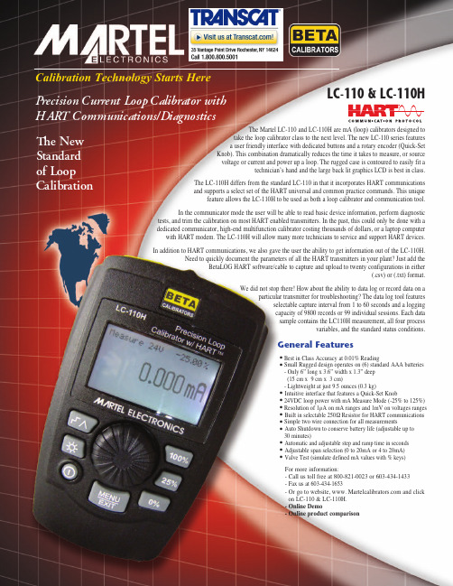
Calibration Technology Starts Here The Martel LC-110 and LC-110H are mA (loop) calibrators designed to take the loop calibrator class to the next level. The new LC-110series features a user friendly interface with dedicated buttons and a rotary encoder (Quick-Set Knob). This combination dramatically reduces the time it takes to measure, or source voltage or current and power up a loop. The rugged case is contoured to easily fit a technician’s hand and the large back lit graphics LCD is best in class. The LC-110H differs from the standard LC-110 in that it incorporates HART communications and supports a select set of the HART universal and common practice commands. This unique feature allows the LC-110H to be used as both a loop calibrator and communication tool.In the communicator mode the user will be able to read basic device information, perform diagnostic tests, and trim the calibration on most HART enabled transmitters. In the past, this could only be done with a dedicated communicator, high-end multifunction calibrator costing thousands of dollars, or a laptop computer with HART modem. The LC-110H will allow many more technicians to service and support HART devices.In addition to HART communications, we also gave the user the ability to get information out of the LC-110H. Need to quickly document the parameters of all the HART transmitters in your plant? Just add the BetaLOG HART software/cable to capture and upload to twenty configurations in either (.csv) or (.txt) format. We did not stop there! How about the ability to data log or record data on a particular transmitter for troubleshooting? The data log tool features selectable capture interval from 1 to 60 seconds and a logging capacity of 9800 records or 99 individual sessions. Each data sample contains the LC110H measurement, all four process variables, and the standard status conditions .General Features .Best in Class Accuracy at 0.01% Reading .Small Rugged design operates on (6) standard AAA batteries - Only 6” long x 3.6” width x 1.3” deep (15 cm x 9 cm x 3 cm)- Lightweight at just 9.5 ounces (0.3 kg).Intuitive interface that features a Quick-Set Knob .24VDC loop power with mA Measure Mode (-25% to 125%).Resolution of 1µA on mA ranges and 1mV on voltages ranges .Built in selectable 250Ω Resistor for HART communications .Simple two wire connection for all measurements .Auto Shutdown to conserve battery life (adjustable up to 30 minutes).Automatic and adjustable step and ramp time in seconds .Adjustable span selection (0 to 20mA or 4 to 20mA).Valve Test (simulate defined mA values with % keys)The NewStandardof LoopCalibration For more information:- Call us toll free at 800-821-0023 or 603-434-1433- Fax us at 603-434-1653- Or go to website, www. and click on LC-110 & LC-110H.- Online Demo - Online product comparisonLC-110 & LC-110HP recision Current Loop Calibrator withHART Communications/DiagnosticsMartel Electronics Corporation 3 Corporate Park Drive, Unit 1LC-110 & LC-110HThe LC-110 & LC-110H utilizes a rotary encoder (Quick-Set Knob) to set the output (mA) and also to select the function to implement. The Quick-Set Knob features an integral push button that you press to enter a selection. A dedicated menu key brings up a list of functions. The Quick-Set interface highlights an item on that list, and then pressing the knob (clicking it) selects that item to drive further in the menu. The “Menu/Exit” key is used to go back to the previous menu or exit from menu structure into measure/source mode.All functions and HART commands are accessed in this manner. When used as mA calibrator only, there are dedicated keys for automatic step and ramp generation as well as keys to perform a quick zero and span Distributed by:assetmanagement software.LC110 Series Ordering Information *Each unit comes standard with batteries, manual, test leads (banana to alligator clips), and NIST Cert with Data Part Number Description 1919974LC110 Loop Calibrator 1920024LC110H Loop Calibrator with HART™ Communications 1920050BetaLOG HART Software with Lemo to USB Cable 6161102Soft Carrying Case 1920051LC110H Loop Calibrator Kit:BetaLOG HART Software with Lemo to USB Cable Soft Carrying Case Banana to Mini-grabber® Test Leads 1920049Lemo to USB Cable 5353050Test Leads (1 Pair – Banana to Alligator)5353093Test Leads (1 Pair – Banana to Minigrabber®)。
贝奇9710A电子负载说明书

目录一、概述 (1)1.1产品概要: (1)1.2技术指标 (2)1.2.1主要指标 (2)1.2.2工作环境 (3)1.2.3工作电源 (3)1.2.4外形尺寸 (3)1.2.5重量 (3)二、面板说明 (4)2.1前面板 (4)2.2后面板 (4)2.3按键 (5)2.4显示信息 (5)三、菜单操作 (7)3.1菜单概述 (7)3.2菜单说明 (7)3.3快捷菜单 (9)3.4菜单设置 (9)3.4.1系统配置(System Config) (9)3.4.2负载设置(Load Setup) (11)3.4.3电池测试设置(Battery Test Set) (13)3.4.4动态测试设置(Tran Test Set) (13)3.4.5列表测试设置(List Test Set) (14)3.4.6文件保存(Save File) (16)3.4.7文件调用(Recall File) (16)3.4.8退出菜单(Exit) (17)四、测试操作 (18)4.1定电流工作模式(CC) (18)4.2定电压工作模式(CV) (18)4.3定功率工作模式(CP) (19)4.4定电阻工作模式(CR) (19)4.5电池测试模式 (18)4.6短路测试模式 (19)4.7动态测试模式 (19)4.7.1 连续方式(CONT) (19)4.7.2脉冲方式(PULS) (22)4.7.3触发方式(TRIG) (22)4.8列表测试模式 (22)4.9 保护功能 (23)4.9.1过压保护 (24)4.9.2过流保护 (24)4.9.3过功率保护 (24)4.9.4输入极性反报警 (24)4.9.5过热保护 (24)5.0 设置数据快速调用功能 (25)五、应用实例 (25)5.1 电池测试: (25)5.1.1参数 (25)5.1.2设置 (25)5.1.3测试 (26)5.2动态测试 (26)5.2.1参数 (26)5.2.2设置 (27)5.2.3测试 (28)5.3列表测试 (28)5.3.1参数 (28)5.3.2设置 (28)5.3.3测试 (31)六、成套与保修 (32)附录A远端测量及外触发 (33)A1远端测量 (33)A2外触发 (33)A3引脚配置 (33)感谢您购买本公司产品!使用本仪器前请首先根据说明书最后“成套与保修”事项进行确认,若不符合请尽快与我公司联系,以维护您的权益。
M97系列说明书9710-9712C 2010-12-13

M97系列可编程直流电子负载用户使用手册适用型号M9710/M9711/M9712/M9712B/M9712CMaynuo Electronics 2009II版本号:V1.1南京美尔诺电子有限公司版权所有目录第一章简介 (1)第二章技术规格 (2)2.1主要技术规格 (2)2.2电子负载尺寸图 (4)第三章快速入门 (5)3.1开机自检 (5)3.2如果负载不能启动 (6)3.3前面板和后面板介绍 (7)3.4键盘说明 (8)3.5菜单操作 (9)第四章面板操作 (14)4.1基本操作模式 (14)4.1.1定电流操作模式(CC) (14)4.1.1.1标准定电流模式 (14)4.1.1.2加载卸载定电流模式 (15)4.1.1.3软启动定电流模式 (16)4.1.1.4定电流转定电压模式 (17)4.1.2定电阻操作模式(CR) (18)4.1.2.1 标准定电阻模式 (18)4.1.2.2 加载卸载定电阻模式 (19)4.1.2.3定电阻转定电压模式 (19)I4.1.3.1标准定电压模式 (20)4.1.3.2加载卸载定电压模式 (21)4.1.3.3软启动定电压模式 (22)4.1.4定功率操作模式(CW) (23)4.1.4.1标准定功率模式 (23)4.1.4.2加载卸载定功率模式 (24)4.2动态测试操作 (24)4.2.1连续模式(CONTINUOUS ) (24)4.2.2脉冲模式(PULSE) (25)4.2.3触发模式(TRIGGER) (25)4.2.4 动态测试参数设置 (26)4.2.5波形控制 (26)4.2.5.1方波 (26)4.2.5.2三角波 (26)4.2.5.3梯形波 (27)4.2.6 触发控制 (27)4.2.7 LIST功能 (27)4.2.7.1.编辑LIST列表 (28)4.2.7.2执行LIST功能 (29)4.2.8 自动测试功能 (29)4.2.8.1编辑自动测试列表 (29)4.2.8.2设置自动测试触发输出方式 (31)II4.3输入控制 (32)4.3.1 短路操作(SHORT) (32)4.3.2 输入开关操作 (32)4.4电子负载可操作范围 (32)4.5保护功能 (34)4.5.1 过电压保护(OV) (34)4.5.2 过电流保护(OC) (34)4.5.3 过功率保护(OW) (35)4.5.4 输入极性反接 (35)4.5.5 过温度保护(OH) (35)4.6远端测试功能 (35)4.7蓄电池放电测试操作 (36)4.8快捷方式功能说明 (37)4.9通讯协议 (38)4.9.1 概述 (38)4.9.2 通讯口DB9的定义 (39)4.9.3选择通讯波特率 (40)4.9.4 数据 (40)4.9.5 功能码 (40)4.9.6 差错校验 (40)4.9.7 完整命令帧解析 (41)4.9.8 线圈与寄存器地址分配 (45)III4.9.10 常用操作功能说明 (49)4.9.11 通讯线的选择 (55)IV第一章简介M97系列产品是美尔诺电子公司设计制造的新一代直流电子负载,采用高性能芯片,高速,高精度设计,提供0.1mV,0.01mA的解析度(基本精度为0.03%,基本电流上升速度2.5A/us), 外观新颖,生产工艺科学严谨,相比同类产品,更具性价比。
FITEL S177A系列手持核对融接设备说明书
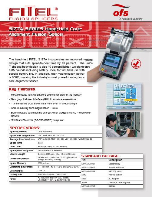
F U S I O N S P L I C E R S A Furukawa Company S177A SERIES Hand-Held Core-Alignment Fusion SplicerThe hand-held FITEL S177A incorporates an improved heatidesign that cuts splice-to-heat time by 40 percent. The uniT-shaped body design is also 40 percent lighter, weighing only4.85 pounds including battery. Ideal for fast fi eld use withsuperb battery life. In addition, fiber magnification poweris 608X, marking the industry’s most powerful rating for acore alignment splicer.Key Features• Most compact, light-weight core-alignment splicer in the industry•New graphical user interface (GUI) to enhance ease-of-use•Transrefl ective LCD allows clear view even in direct sunlight• Best-in-industry fiber magnification – 680X•Built-in battery automatically charges when plugged into AC – even whensplicing• RoHS and Telcordia (GR-765-CORE) compliantheatine unitg onlyheatinge unit’sonly RoHSSPECIFICATIONS:Splicing Method Core-AlignmentApplicable Single Fiber SMF, MMF, DSF, NZDSF, EDFAverage Insertion Loss SMF: 0.02 dB, MMF: 0.01 dB, DSF: 0.04 dB, NZDSF: 0.03 dBSplice Time9 secHeat Time37 sec (40 mm), 51 sec (60 mm)Splice/Heat Programs150 available / 12 availableCleave Lenght5-16 mm (250 µm), 10 or 16 mm (900 µm)Dimension/Weight130W×260D×137H mm / 2.20 kg (4.85 Ibs)[weight including battery]Splice Memory2000 splicesOperating Enviroment0 ~ 4,000 m, -10 to +50° C and 90% at 38° CData Output USB 1.1Battery Life Internal - 70 splice / heat cyclesPower AC Input : 85 to 264 V (50 / 60 Hz),DC Input : 11 to 17 V, Battery : Li-ionSTANDARD PACKAGE:P/N DescriptionS177-X-A-0001Splicer BodyS177-X-S-0002Spare ElectrodesS177-X-A-0003Carrying CaseS943Internal BatteryS957AC AdapterD5111Electrode Cleaning DiskS177-X-S-0004ManualA Furukawa CompanyUse electronic fi les, available at: - Use less paperSeamless Splicing from Trunk to FTTXThe FITEL S177A ushers in a whole new range of applications for core-alignment splicing: It delivers the same precision, accuracy, and automated functionality of a conventional core-alignment unit, but with the speed, portability, and covenience of a hand-held splicer. The S177A becomes your versatile best choice for FTTX, LAN, backbone, or long-haul installations.Compact, Lightweight BodyAt nearly half the weight and size of FITEL's standard core-alignment unit, the S177A weight only 2.2 kgs (4.85 pounds) – making it the fi rst hand-held and most compact, lightweight core-aligning splicer in the industry. The T-shaped body desigh, measuring just 5 inches across, easily accommodates short fi ber lengths. The magnesium alloy canopy and top base provide the rugged strength required for fi eld operations. Highly accurate, it easily handles diverse applications-from trunk splicing to FTTX.New GUI & LCD ScreenF eaturing a new GUI (graphical user interface) and transrefl ective LCD screen technol-ogy, the S177A operation is a snap! Function keys are simple and information displays are crisp and clear even in direct sunlight. The LCD display shows the splicing process with simultaneous X and Y views, Fiber magnifi cation is the highestavailableintheindustry – 608X, and over 200 percent stronger then FITEL's previous model, the S176.OPTIONAL ACCESSORIES:P/NDescription P/NDescriptionS177-X-S-0005Cooling TrayS707S-900900 μm Fiber Holder S177-X-S-0006USB CordS707S-400400 μm Fiber Holder S177-X-S-0007Fiber Holder Mount S210Furukawa Fiber Stripper S707S-08080 μm Fiber Holder S211Miller StripperS707S-250250 μm Fiber HolderS325AHand-Held High Precision Cleaver n Clen Cleaver ORDERING NUMBER FORM:Cleave Length0: 16 mm Tight Holder 125 / 250 µm: 5 ~ 16 mm; 125 / 900 µm: 16 mm1: 10 mm Tight Holder 80 / 150 ~ 200 µm: 5 mm; 125 / 250 µm: 5 ~ 10 mm; 125 / 900 µm: 10 mm 2: Fiber Holder SystemSOC Applicable 80 / 150 ~ 200 µm: 5 mm; 125 / 250 ~ 900 µm: 10 mm 3: Loose-Tube-Holder 125 / 250 µm: 5 ~ 10 mmS177A -Fiber Holder Type Contact Us:Fusion Splicer Customer Service,Training and Service Center417 Dividend DrivePeachtree City, GA 30269, USA Toll Free: 866-452-9516Phone: 678-783-1090Fax: 678-783-1093Email: **********************OFS Corporate Headquarters2000 Northeast Expressway Norcross, Georgia 30071, USA Toll Free: 888-Fiber-Help Intl. Phone: 770-798-5555Email: *****************For additional information please conta contact your salesrepresentative. You can also visit our website at: .FITEL is a trademark of Furukawa Denki KogyoKabushiki Kaisha DBA The Furukawa Electric Co., Ltd Corporation.OFS reserves the right to make changes to the prices and product(s) described in this document in the interest of improving internal design, operational function, and/or reliability.This document is for informational purposes only and is ment is for informational purposes only and is not intended to modify or supplement any OFS warranties or specifi cations relating to any of its products or services.Copyright © 2009 OFS FITEL, LLC.All rights reserved, printed in USA.OFSMarketing Communications FITEL-S177A-0809。
美国Thermofisher精密移液器使用说明 - zoomingivfcom

美国Thermofisher精密移液器使用说明1、调节量程在调节量程时,如果要从大体积调为小体积,则按照正常的调节方法,逆时针旋转旋钮即可;但如果要从小体积调为大体积时,则可先顺时针旋转刻度旋钮至超过量程的刻度,再回调至设定体积,这样可以保证量取的最高精确度。
在该过程中,千万不要将按钮旋出量程,否则会卡住内部机械装置而损坏了移液枪。
2、装配枪头(吸液嘴)在将枪头套上移液枪时,正确的方法是将移液枪(器)垂直插入枪头中,稍微用力左右微微转动即可使其紧密结合。
如果是多道(如8道或12道)移液枪,则可以将移液枪的第一道对准第一个枪头,然后倾斜地插入,往前后方向摇动即可卡紧。
枪头卡紧的标志是略为超过O型环,并可以看到连接部分形成清晰的密封圈。
3、移液的方法移液之前,要保证移液器、枪头和液体处于相同温度。
吸取液体时,移液器保持竖直状态,将枪头插入液面下2-3毫米。
在吸液之前,可以先吸放几次液体以润湿吸液嘴(尤其是要吸取粘稠或密度与水不同的液体时)。
这时可以采取两种移液方法。
一是前进移液法。
用大拇指将按钮按下至第一停点,然后慢慢松开按钮回原点。
接着将按钮按至第一停点排出液体,稍停片刻继续按按钮至第二停点吹出残余的液体。
最后松开按钮。
二是反向移液法。
此法一般用于转移高粘液体、生物活性液体、易起泡液体或极微量的液体,其原理就是先吸入多于设置量程的液体,转移液体的时候不用吹出残余的液体。
先按下按钮至第二停点,慢慢松开按钮至原点。
接着将按钮按至第一停点排出设置好量程的液体,继续保持按住按钮位于第一停点(千万别再往下按),取下有残留液体的枪头,弃之。
4、移液器的正确放置使用完毕,可以将其竖直挂在移液枪架上,但要小心别掉下来。
当移液器枪头里有液体时,切勿将移液器水平放置或倒置,以免液体倒流腐蚀活塞弹簧。
5、维护保养时的注意事项如不使用,要把移液枪的量程调至最大值的刻度,使弹簧处于松弛状态以保护弹簧。
最好定期清洗移液枪,可以用肥皂水或60%的异丙醇,再用蒸馏水清洗,自然晾干。
优利德 UTL8200+系列使用手册 说明书
UTL8200+系列直流电子负载用户手册REV 02023.02尊敬的用户:您好!感谢您选购全新的优利德仪器,为了正确使用本仪器,请您在本仪器使用之前仔细阅读本说明书全文,特别有关“安全注意事项”的部分。
如果您已经阅读完本说明书全文,建议您将此说明书进行妥善的保管,与仪器一同放置或者放在您随时可以查阅的地方,以便在将来的使用过程中进行查阅。
优利德科技(中国)股份有限公司版权所有。
如果原购买者自购买该产品之日起三年内,将该产品出售或转让给第三方,则保修期应为自原购买者从UNI-T或授权的UNI-T分销商购买该产品之日起三年内。
探头及其他附件和保险丝等不受此保证的保护。
如果在适用的保修期内证明产品有缺陷,UNI-T可自行决定是修复有缺陷的产品且不收部件和人工费用,或用同等产品(由UNI-T决定)更换有缺陷的产品。
UNI-T作保修用途的部件、模块和更换产品可能是全新的,或者经修理具有相当于新产品的性能。
所有更换的部件、模块和产品将成为UNI-T的财产。
以下提到的“客户”是指据声明本保证所规定权利的个人或实体。
为获得本保证承诺的服务,“客户”必须在适用的保修期内向UNI-T通报缺陷,并为服务的履行做适当安排。
客户应负责将有缺陷的产品装箱并运送到UNI-T指定的维修中心,同时预付运费并提供原购买者的购买证明副本。
如果产品要运送到UNI-T维修中心所在国范围内的地点,UNI-T应支付向客户送返产品的费用。
如果产品送返到任何其他地点,客户应负责支付所有的运费、关税、税金及任何其他费用。
本保证不适用于由于意外、机器部件的正常磨损、在产品规定的范围之外使用或使用不当或者维护保养不当或不足而造成的任何缺陷、故障或损坏。
UNI-T根据本保证的规定无义务提供以下服务:a) 修理由非UNI-T服务代表人员对产品进行安装、修理或维护所导致的损坏;b) 修理由于使用不当或与不兼容的设备连接造成的损坏;c) 修理由于使用不符合本说明书要求的电源而造成的任何损坏或故障;d) 维修已改动或者与其他产品集成的产品(如果这种改动或集成会增加产品维修的时间或难度)。
道努尔(Dorner)MFG. CORP. 1100系列远程信号直流电机控制器操作手册说明书
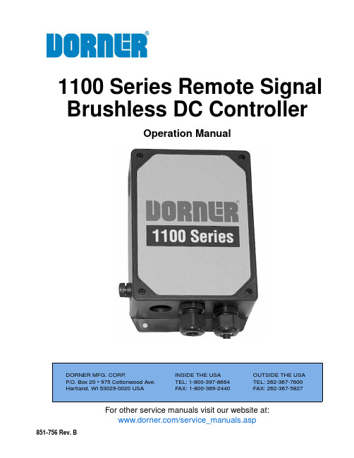
For other service manuals visit our website at:/service_manuals.aspDORNER MFG. CORP .INSIDE THE USA OUTSIDE THE USA P .O. Box 20 • 975 Cottonwood Ave.TEL: 1-800-397-8664TEL: 262-367-7600Hartland, WI 53029-0020 USA FAX: 1-800-369-2440FAX: 262-367-5827851-756 Rev. B1100 Series Remote Signal Brushless DC ControllerOperation ManualDorner Mfg. Corp.2851-756 Rev. B1100 Series Remote Signal Brushless DC ControllerTable of ContentsIntroduction......................................................................... 2Warnings - General Safety.................................................. 3Operations............................................................................ 4Remote Wired Options.................................................... 4Input Signals.................................................................... 4START/STOP Input..................................................... 4CW/CCW Input............................................................ 4Setting The Running Speed (5)Setting By Internal Potentiometer................................. 5Speed Control with Internal Potentiometer............... 5Setting By External Potentiometer............................... 6Speed Control with External Potentiometer (customer supplied).................................................................... 7Setting By External DC Voltage................................... 8Return Policy. (10)IntroductionUpon receipt of shipment:•Compare shipment with packing slip. Contact factory regarding discrepancies.•Inspect packages for shipping damage. Contact carrier regarding damage.•Accessories may be shipped loose. See accessory instruc-tions for installation.Dorner’s Limited Warranty applies.Dorner 1100 series conveyors have patents pending.Dorner reserves the right to make changes at any time without notice or obligation.Dorner has convenient, pre −configured kits of Key Service Parts for all conveyor products. These time saving kits are easy to order, designed for fast installation, and guarantee you will have what you need when you need it. Key Parts and Kits are marked in the Service Parts section of thismanual with the Performance Parts Kits logo.IMPORTANTSome illustrations may show guards removed. DO NOT operate equipment without guards.851-756 Rev. B3Dorner Mfg. Corp.1100 Series Remote Signal Brushless DC ControllerWarnings - General SafetyA WARNINGThe safety alert symbol, black triangle with white exclamation, is used to alert you to potential personal injury hazards.Climbing, sitting, walking or riding on conveyor will cause severe injury.KEEP OFF CONVEYORS.DO NOT OPERATE CONVEYORS IN ANEXPLOSIVE ENVIRONMENT.A WARNINGExposed moving parts can cause severe injury.LOCK OUT POWER before removing guards or performing maintenance.Hazardous voltage will cause severe injury or death.LOCK OUT POWER BEFORE WIRING.A WARNINGGearmotors may be HOT.DO NOT TOUCH Gearmotors.A WARNINGExposed moving parts can cause severe injury.REPLACE ALL GUARDS BEFORE RUNNING CONVEYOR.A WARNINGDorner cannot control the physicalinstallation and application of conveyors. Taking protective measures is the responsibility of the user.When conveyors are used in conjunction with other equipment or as part of a multiple conveyor system, CHECK FOR POTENTIAL PINCH POINTS and other mechanical hazards before system start-up.Dorner Mfg. Corp.4851-756 Rev. B1100 Series Remote Signal Brushless DC ControllerOperationsRemote Wired OptionsRefer to Figure 1 for controller components.Figure 1Input SignalsSTART/STOP InputSTART is selected when the input is ON, and motor starts running. The motor accelerates over the time set by the acceleration/deceleration time potentiometer. STOP isselected when the input is OFF, and motor stops. The motor decelerates over the time set by the acceleration/deceleration time potentiometer.CW/CCW InputCW is selected when the input is ON. CCW is selected when the input is OFF. The drive direction is the same as that of the motor output shaft when viewed from the motor output side.1Customer Interface Terminal Block 2DC Driver BLH2303Motor Connection Terminal 4Grounding Screw5Customer Interface Cable (Input to Enclosure)6Motor Cable Input to Enclosure (Cord Grip Included Inside)7Fuse8Connector CN29Power SupplyNOTEFor customer supplied wiring:•Use shielded, multi-conductor cable for input signal.•Wires to be AWG26 minimum.•Shield of multi-conductor cable should be grounded to sub panel.156243789A CAUTIONDo not perform the motor’s starting and stopping operations by turning the power supply on and off.Perform them by inputting START/STOP.Failure to use START/STOP may cause injury or damage to the equipment.NOTE•The input signals (START/STOP and CW/CCW) must be ON for at least 10 ms. It may cause malfunction of the motor.•Do not operate (switch the ON/OFF status) of the START/STOP input, CW/CCW input, and INT.VR/EXT input simultaneously. After switching a given input, wait at least 10 ms before switching another input.NOTEDepending on the gearhead ratio, the drive direction of the gear output shaft may be opposite of that of the motor.851-756 Rev. B5Dorner Mfg. Corp.1100 Series Remote Signal Brushless DC ControllerOperationsSetting The Running SpeedSet the operating speed of the motor using the internal speed potentiometer, external speed potentiometer or external DC voltage. The motor speed range is from 100 to 3000 rpm for the case of the motor alone. Dorner speed ranges are 100 to 2500 rpm for constant motor torque.Setting By Internal PotentiometerThis potentiometer is used when running speed setting is not frequently changed.Adjust the potentiometer using an insulated screwdriver. Clockwise rotation will increase the set speed. The speed is set to 0 r/min at time of shipment.Speed Control with Internal Potentiometer1.Adjust desired accel/decel at driver (Figure 2,item 1).Figure 2Figure 32.Connect light blue wire to terminal 2 (COM).3.Adjust desired speed at driver (Figure 2,item 2).Hazardous voltage will cause severe injury or death.LOCK OUT POWER BEFORE WIRING.1Accel/Decel Time Potentiometer 2Internal Speed PotentiometerNOTEThe light blue wire from the controller board is ordinarily not used if it is taped off. It must be separated from the harness and connected to terminal 2 (COM) as shown in (Figure 3).12Dorner Mfg. Corp.6851-756 Rev. B1100 Series Remote Signal Brushless DC ControllerOperations4.Insert multi-conductor cable into cord grip (Figure 4,item 1).Figure 45.Wire START/STOP, COM, and CW/CCW to terminal (Figure 4,item 2).6.Install motor cord through interface location (Figure 4,item 3). Refer to Motor Manual 851-748 or 851-749 for details.Setting By External PotentiometerThis potentiometer is used when the speed is set away from the driver.Use a 20 Kohm, 1/4 watt, linear resistance vs angle, external potentiometer. Clockwise rotation will increase the set speed.Figure 5* Indicates the speed of the motor alone. The speed of the gear output shaft of a geared type or combination type is obtained by dividing the motor speed by the gear ratio.123851-756 Rev. B7Dorner Mfg. Corp.1100 Series Remote Signal Brushless DC ControllerOperationsSpeed Control with External Potentiometer (customer supplied)1.Adjust desired accel/decel at driver (Figure 6,item 1).Figure 6Figure 72.Insert shielded cable for external potentiometer into cord grip (Figure 8,item 1). Connect high, med, and low to 6, 5, and 4 as shown in (Figure 7).Figure 83.Wire START/STOP, COM, and CW/CCW to terminal (Figure 8,item 2), as shown in (Figure 7).4.Install motor cord through interface location (Figure 8,item 3). Refer to Motor Manual 851-748 or 851-749 for details.1Accel/Decel Time Potentiometer1NOTEUse a shielded cable for connection with the external potentiometer. Connection should be made close to the driver. Connect the shielded wire to the ground.123Dorner Mfg. Corp.8851-756 Rev. B1100 Series Remote Signal Brushless DC ControllerOperationsSetting By External DC VoltageExternal DC voltage is used when the speed is set by D/A output from an external control device such as a programmable controller.For external DC voltage, use DC power supply (0 to 5 VDC, 1 mA or more) where the primary and secondary sides are provided with reinforced insulation.Figure 9* Indicates the speed of the motor alone. The speed of the gear output shaft of a geared type or combination type is obtained by dividing the motor speed by the gear ratio.Figure 101.Adjust desired accel/decel at driver (Figure 11,item 1).Figure 11NOTE•The external DC power supply voltage must not exceed 5 VDC. Otherwise, the driver may be damaged.•When connecting the external DC power supply, sufficient care must be taken not to mistake power polarity. Connection with incorrect polarity may damage the driver.•Use a shielded cable for connection with the external DC power supply. Connectionshould be made close to the driver. Connect the shielded wire to the ground.1851-756 Rev. B9Dorner Mfg. Corp.1100 Series Remote Signal Brushless DC ControllerOperations2.Insert multi-conductor cable into cord grip (Figure 12,item 1).Figure 123.Wire START/STOP, COM, and CW/CCW to terminal (Figure 12,item 2).4.Wire DC control speed signal negative to location 4 and positive to location 5 as shown in (Figure 10).5.Install motor cord through interface location (Figure 12,item 3). Refer to Motor Manual 851-748 or 851-749 for details.123851-756 Rev. B Printed in U.S.A.Dorner Mfg. Corp. reserves the right to changeor discontinue products without notice. All products and services are covered inaccordance with our standard warranty. All rights reserved. © Dorner Mfg. Corp. 2013DORNER MFG. CORP .975 Cottonwood Ave., PO Box 20 Hartland, WI 53029-0020 USA TEL 1-800-397-8664 (USA)FAX 1-800-369-2440 (USA)Internet: Outside the USA:TEL 1-262-367-7600FAX 1-262-367-58277Return PolicyReturns must have prior written factory authorization or they will not be accepted. Items that are returned to Dorner without authorization will not be credited nor returned to the original sender. When calling for authorization, please have the following information ready for the Dorner factory representative or your local distributor: and address of customer.2.Dorner part number(s) of item(s) being returned.3.Reason for return.4.Customer's original order number used when ordering the item(s).5.Dorner or distributor invoice number (if available, part serial number).A representative will discuss action to be taken on the returned items and provide a Returned Goods Authorization (RMA) number for reference. RMA will automatically close 30 days after being issued. To get credit, items must be new andundamaged. There will be a return charge on all items returned for credit, where Dorner was not at fault. It is the customer’s responsibility to prevent damage during return shipping. Damaged or modified items will not be accepted. The customer is responsible for return freight.Returns will not be accepted after 60 days from original invoice date. The return charge covers inspection, cleaning,disassembly, disposal and reissuing of components to inventory. If a replacement is needed prior to evaluation of returned item, a purchase order must be issued. Credit (if any) is issued only after return and evaluation is complete.Dorner has representatives throughout the world. Contact Dorner for the name of your local representative. Our Customer Service Team will gladly help with your questions on Dorner products.For a copy of Dorner's Warranty, contact factory, distributor, service center or visit our website at .For replacement parts, contact an authorized Dorner Service Center or the factory.Product TypeStandard ProductsEngineered to order partsProduct LineConveyors Gearmotors & Mounting Packages Support Stands Accessories Spare Parts (non-belt)Spare Belts - Standard Flat Fabric Spare Belts - Cleated & Specialty FabricSpare Belts -Plastic Chain All equipment and parts110030% return fee for all products except:50% return fee for conveyors with modular belt,cleated belt or specialty beltsnon-returnablecase-by-case22002200 Modular Belt 2200 Precision Move 23002300 Modular Belt 32003200 LPZ3200 Precision Move 4100520053006200Controls 7200 / 730050% return fee for all products7350non-returnable736074007600。
ART-M721 型自动化仪表综合校验仪使用说明书
ART-M721 型自动化仪表综合校验仪使用说明书ART-M721 型自动化仪表综合校验仪是一种集数显式电压、电流、频率标准信号源、Pt100铂电阻温度模拟标准信号源、数字式电压、电流、频率测量功能于一体的高精度、高分辨率、多用途的自动化仪表校准仪器。
它具有信号输出和测试功能,可校验以下各类仪表:以模拟量输入输出的传感器、变送器、调节器、记录仪、智能流量积算仪、电/气执行器等常规的工业自动化仪表。
还可以用于校验和整定计算机一系列接口板卡,如电阻板、A/D板、D/A板等。
可广泛应用于石油、化工、冶炼、造纸、发电、仪表行业及科研部门等领域。
其技术性能符合电II 型、电III 型自动化仪表校验标准,工作环境符合GB6587.1-86《电子测量仪器环境试验总纲》中两组仪器的有关规定。
它与国内外同类仪表相比具有以下四大特色:∙功能较全,它几乎包括了自动化仪表所有的电信号;精度高、体积小、重量轻,尤其可直接应用于现场,对各种工业过程控制的自动化仪表实施现场调校、检修。
∙可同时输出三路有源毫安信号,极大地方便了需多路输入信号仪表(如智能流量积算仪、弯管流量计等)的校验和检修。
∙有宽量程的交流工作电压范围(180~260V.AC),能适应工业现场恶劣的工作环境。
∙仪表可同时工作在测量和输出状态,有两个四位半LED显示器,每个显示器有四只单位显示灯,分别显示mA、mV、V、KHz。
通过选择可同时显示输出值及其单位和测量值及其单位。
一.功能输出功能:1.有可作为两线制变送器使用的0~25.00V.DC连续可调工作电源,有一路0~199.99mV.DC直流电压信号,可作为各种热电偶的模拟输出信号。
2.具有两路Pt100热电阻模拟器,可输出Pt100铂电阻-50℃、-20℃、-3℃、-8℃、0℃、7℃、11℃、50℃、100℃、150℃、160℃、170℃、190℃、200℃、250℃、300℃的模拟电阻信号,可作温度变送器输入信号使用。
胜利仪器 VICTOR 3801MS 3802MS单通道可编程电子负载用户手册 说明书

目录产品基本功能 (1)1.快速入门 (2)1.1.前面板液晶显示 (2)1.2.前面板按键 (2)2.功能操作 (3)2.1.模式选择 (3)2.2.量程切换 (4)2.3.通道开关 (4)2.4.远程/本地切换操作 (4)2.5.系统设置操作 (4)2.5.1.保存参数 (5)2.5.2.调用参数 (5)2.5.3.电压量程 (6)2.5.4.电流量程 (6)2.5.5.极限电压/电流/功率值 (6)2.5.6.触发源选择 (7)2.5.7.启动电压与关断电压 (7)2.5.8.开机设置 (7)2.5.9.蜂鸣器 (8)2.5.10.恢复出厂设置 (8)2.5.11.背光亮度 (8)2.5.12.RS485地址 (8)2.5.13.波特率 (9)2.5.14.通讯模式 (9)2.5.15.合格测试与合格测试限制值 (9)2.5.16.系统信息 (10)3.基本模式操作 (10)3.1.定电流模式(CC) (10)3.1.1.主显示界面 (10)3.1.2.参数编辑 (11)3.1.3.工作状态 (11)3.2.定电压模式(CV) (12)3.3.定功率模式(CP) (12)3.4.定电阻模式(CR) (13)4.动态测试操作(DYNA) (13)4.1.主显示界面 (13)4.2.参数编辑 (14)4.3.工作状态 (15)5.列表测试操作(LIST) (15)5.1.主显示界面 (15)5.2.参数编辑 (16)5.3.工作状态 (18)6.扫描测试操作(SCAN) (18)6.1.主显示界面 (18)6.2.参数编辑 (19)6.3.工作状态 (20)7.电池测试操作(BATT) (21)7.1.主显示界面 (21)7.2.参数编辑 (22)7.3.工作状态 (24)7.3.1.例子:CC恒流放电,截止条件为电压 (24)8.短路测试操作(SHORT) (25)9.保护/提示功能 (25)10.合格测试操作 (25)11.其他系统设置 (26)11.1.键盘锁功能 (26)11.2.通讯口和外部接口功能 (26)技术规格 (27)产品基本功能本系列仪器为直流可编程电子负载,提供1mV/10mV,1mA/10mA的高解析度和精度,性能优越。
M97使用手册

M97系列可编程直流电子负载用户使用手册适用型号M9711/M9712/M9712B/M9712C/M9712B30Maynuo Electronics 2009II版本号:V1.1南京美尔诺电子有限公司版权所有目录第一章简介 (1)第二章技术规格 (2)2.1主要技术规格 (2)2.2电子负载尺寸图 (6)第三章快速入门 (7)3.1开机自检 (7)3.2如果负载不能启动 (8)3.3前面板和后面板介绍 (9)3.4键盘说明 (10)3.5菜单操作 (11)第四章面板操作 (16)4.1基本操作模式 (16)4.1.1定电流操作模式(CC) (16)4.1.1.1标准定电流模式 (16)4.1.1.2加载卸载定电流模式 (17)4.1.1.3软启动定电流模式 (18)4.1.1.4定电流转定电压模式 (19)4.1.2定电阻操作模式(CR) (19)4.1.2.1 标准定电阻模式 (20)4.1.2.2 加载卸载定电阻模式 (20)4.1.2.3定电阻转定电压模式 (21)4.1.3定电压操作模式(CV) (21)4.1.3.1标准定电压模式 (22)4.1.3.2加载卸载定电压模式 (22)4.1.3.3软启动定电压模式 (23)4.1.4定功率操作模式(CW) (24)4.1.4.1标准定功率模式 (24)4.1.4.2加载卸载定功率模式 (25)4.2动态测试操作 (26)4.2.1连续模式(CONTINUOUS ) (26)4.2.2脉冲模式(PULSE) (26)4.2.3触发模式(TRIGGER) (27)4.2.4 动态测试参数设置 (27)4.2.5波形控制 (28)4.2.5.1方波 (28)4.2.5.2三角波 (28)4.2.5.3梯形波 (28)I4.2.6 触发控制 (28)4.2.7 LIST功能 (29)4.2.7.1.编辑LIST列表 (29)4.2.7.2执行LIST功能 (30)4.2.8 自动测试功能 (30)4.2.8.1编辑自动测试列表 (31)4.2.8.2设置自动测试触发输出方式 (32)4.2.8.3执行自动测试功能 (33)4.3输入控制 (33)4.3.1 短路操作(SHORT) (33)4.3.2 输入开关操作 (33)4.4电子负载可操作范围 (34)4.5保护功能 (34)4.5.1 过电压保护(OV) (34)4.5.2 过电流保护(OC) (35)4.5.3 过功率保护(OW) (35)4.5.4 输入极性反接 (36)4.5.5 过温度保护(OH) (36)4.6远端测试功能 (36)4.7蓄电池放电测试操作 (36)4.8快捷方式功能说明 (38)4.9通讯协议 (39)4.9.1 概述 (39)4.9.2 通讯口DB9的定义 (40)4.9.3 选择通讯波特率 (41)4.9.4 数据 (41)4.9.5功能码 (41)4.9.6 差错校验 (41)4.9.7 完整命令帧解析 (42)4.9.8 线圈与寄存器地址分配 (46)4.9.9 命令寄存器CMD定义 (49)4.9.10常用操作功能说明 (50)4.9.11 通讯线的选择 (56)II第一章简介M97系列产品是美尔诺电子公司设计制造的新一代直流电子负载,采用高性能芯片,高速,高精度设计,提供0.1mV,0.01mA的解析度(基本精度为0.03%,基本电流上升速度2.5A/us), 外观新颖,生产工艺科学严谨,相比同类产品,更具性价比。
电子负载仪适用说明
M97系列可编程直流电子负载
用户使用手册
适用型号M9711/M9712/M9712B/M9712C/M9712B30
Maynuo Electronics 2009
目录
第一章 简介...............................................................................................................................................1
4.1.4 定功率操作模式(CW) .......................................................................................................24 4.1.4.1 标准定功率模式...............................................................................................................24 4.1.4.2 加载卸载定功率模式.......................................................................................................25
M88系列可编程直流电源使用说明书
胜利仪器 VICTOR 3721 3722可编程线性直流稳压电源说明书
请勿在仪器机箱打开时运行本产品。
避免电路外露。
电源接通后,请勿接触外露的接头和元件。
怀疑产品出故障时,请勿进行操作。
如果您怀疑本产品出现故障,请联络代理商人员进行检测。
保持适当的通风。
通风不良会引起仪器温度升高,进而引起仪器损坏。使用时应保持良好的通风, 定期检查通风口和风扇。
请勿在潮湿环境下操作。
为避免仪器内部电路短路或发生电击的危险,请勿在潮湿环境下操作仪器。
请勿在易燃易爆的环境下操作。
为避免仪器损坏或人身伤害,请勿在易燃易爆的环水分影响仪器性能,请保持产品表面的清洁和干燥。
防静电保护。
静电会造成仪器损坏,应尽可能在防静电区进行测试。在连接电缆到仪器前,应 将其内外导体短暂接地以释放静电。
2.1 前面板........................................................................................................................3 2.2 后面板........................................................................................................................4 2.3 用户界面....................................................................................................................4
主要特点: 单路独立可调输出 1 路 2.5V/3.3V/5V 档位可调固定输出 出色的电源调整率 出色的负载调整率 支持最大 112 组定时输出 支持最大 10 组设置文件保存 高精度输出分辨率 4.3 英寸(480*272)高分辨率 TFT 液晶显示屏 支持 USB2.0 通讯 支持系统语言中英文切换
美尔诺M9711-9712系列电子负载使用手册

M97系列可编程直流电子负载用户使用手册适用型号M9711/M9712/M9712B/M9712C/M9712B30Maynuo Electronics 2009II版本号:V1.1南京美尔诺电子有限公司版权所有目录第一章简介 (1)第二章技术规格 (2)2.1主要技术规格 (2)2.2电子负载尺寸图 (6)第三章快速入门 (7)3.1开机自检 (7)3.2如果负载不能启动 (8)3.3前面板和后面板介绍 (9)3.4键盘说明 (10)3.5菜单操作 (11)第四章面板操作 (16)4.1基本操作模式 (16)4.1.1定电流操作模式(CC) (16)4.1.1.1标准定电流模式 (16)4.1.1.2加载卸载定电流模式 (17)4.1.1.3软启动定电流模式 (18)4.1.1.4定电流转定电压模式 (19)4.1.2定电阻操作模式(CR) (19)4.1.2.1 标准定电阻模式 (20)4.1.2.2 加载卸载定电阻模式 (20)4.1.2.3定电阻转定电压模式 (21)4.1.3定电压操作模式(CV) (21)4.1.3.1标准定电压模式 (22)4.1.3.2加载卸载定电压模式 (22)4.1.3.3软启动定电压模式 (23)4.1.4定功率操作模式(CW) (24)4.1.4.1标准定功率模式 (24)4.1.4.2加载卸载定功率模式 (25)4.2动态测试操作 (26)4.2.1连续模式(CONTINUOUS ) (26)4.2.2脉冲模式(PULSE) (26)4.2.3触发模式(TRIGGER) (27)4.2.4 动态测试参数设置 (27)4.2.5波形控制 (28)4.2.5.1方波 (28)4.2.5.2三角波 (28)4.2.5.3梯形波 (28)I4.2.6 触发控制 (28)4.2.7 LIST功能 (29)4.2.7.1.编辑LIST列表 (29)4.2.7.2执行LIST功能 (30)4.2.8 自动测试功能 (30)4.2.8.1编辑自动测试列表 (31)4.2.8.2设置自动测试触发输出方式 (32)4.2.8.3执行自动测试功能 (33)4.3输入控制 (33)4.3.1 短路操作(SHORT) (33)4.3.2 输入开关操作 (33)4.4电子负载可操作范围 (34)4.5保护功能 (34)4.5.1 过电压保护(OV) (34)4.5.2 过电流保护(OC) (35)4.5.3 过功率保护(OW) (35)4.5.4 输入极性反接 (36)4.5.5 过温度保护(OH) (36)4.6远端测试功能 (36)4.7蓄电池放电测试操作 (36)4.8快捷方式功能说明 (38)4.9通讯协议 (39)4.9.1 概述 (39)4.9.2 通讯口DB9的定义 (40)4.9.3 选择通讯波特率 (41)4.9.4 数据 (41)4.9.5功能码 (41)4.9.6 差错校验 (41)4.9.7 完整命令帧解析 (42)4.9.8 线圈与寄存器地址分配 (46)4.9.9 命令寄存器CMD定义 (49)4.9.10常用操作功能说明 (50)4.9.11 通讯线的选择 (56)II第一章简介M97系列产品是美尔诺电子公司设计制造的新一代直流电子负载,采用高性能芯片,高速,高精度设计,提供0.1mV,0.01mA的解析度(基本精度为0.03%,基本电流上升速度2.5A/us), 外观新颖,生产工艺科学严谨,相比同类产品,更具性价比。
Belimo LR24A-MF 配置可调旋钮式电动阀控制器说明书

LR24A-MFConfigurable rotary actuator for ball valves • Torque motor 5 Nm• Nominal voltage AC/DC 24 V• Control modulating 2...10 V variable • Position feedback 2...10 V variableTechnical dataElectrical data Nominal voltageAC/DC 24 V Nominal voltage frequency 50/60 Hz Nominal voltage rangeAC 19.2...28.8 V / DC 21.6...28.8 VPower consumption in operation2.5 W Power consumption in rest position 1.2 W Power consumption for wire sizing 5 VAConnection supply / control Cable 1 m, 4 x 0.75 mm²Parallel operationYes (note the performance data)Functional dataTorque motor 5 Nm Operating range Y 2...10 V Input Impedance100 kΩOperating range Y variableStart point 0.5...30 V End point 2.5...32 V Operating modes optionalOpen/close3-point (AC only)Modulating (DC 0...32 V)Position feedback U2...10 V Position feedback U note Max. 0.5 mA Position feedback U variable Start point 0.5...8 V End point 2.5...10 V Position accuracy ±5%Manual override with push-button, can be lockedRunning time motor 90 s / 90°Running time motor variable 35...150 s Adaptation setting range manual (automatic on first power-up)Adaptation setting range variableNo actionAdaptation when switched onAdaptation after pushing the gear disengagement buttonOverride controlMAX (maximum position) = 100%MIN (minimum position) = 0%ZS (intermediate position, AC only) = 50%Override control variableMAX = (MIN + 33%)...100%MIN = 0%...(MAX – 33%)ZS = MIN...MAX Sound power level, motor 35 dB(A)Position indicationMechanically, pluggableSafety dataProtection class IEC/EN III, Safety Extra-Low Voltage (SELV)Power source ULClass 2 Supply Degree of protection IEC/EN IP54Degree of protection NEMA/ULNEMA 2P ro du ct nol on ge r a v a i l ab l eLR24A-MF•••••••Mode of operationParametrisable actuators Simple direct mountingManual overrideAdjustable angle of rotation High functional reliabilitySafety dataEnclosure UL Enclosure Type 2EMCCE according to 2014/30/EUCertification IEC/EN IEC/EN 60730-1 and IEC/EN 60730-2-14Certification ULcULus according to UL60730-1A, UL60730-2-14 and CAN/CSA E60730-1The UL marking on the actuator depends on the production site, the device is UL-compliant in any case Mode of operationType 1Rated impulse voltage supply / control 0.8 kV Pollution degree 3Ambient temperature -30...50°CStorage temperature -40...80°C Ambient humidity Max. 95% RH, non-condensing Servicingmaintenance-free WeightWeight 0.59 kgSafety notesThis device has been designed for use in stationary heating, ventilation and air-conditioning systems and must not be used outside the specified field of application, especially in aircraft or in any other airborne means of transport.Outdoor application: only possible in case that no (sea) water, snow, ice, insolation or aggressive gases interfere directly with the device and that it is ensured that the ambient conditions remain within the thresholds according to the data sheet at any time.Only authorised specialists may carry out installation. All applicable legal or institutional installation regulations must be complied during installation.The switch for changing the direction of rotation may only be operated by authorisedspecialists. The direction of rotation must not in particular be reversed in a frost protection circuit.The device may only be opened at the manufacturer's site. It does not contain any parts that can be replaced or repaired by the user.Cables must not be removed from the device.The device contains electrical and electronic components and must not be disposed of as household refuse. All locally valid regulations and requirements must be observed.Product featuresThe actuator is connected with a standard control signal of 0...10 V and drives to the position defined by the control signal. Measuring voltage U serves for the electrical display of the valve position 0.5...100% and as control signal for other actuators.The factory settings cover the most common applications. Single parameters can be modified with the Belimo Service Tools MFT-P or ZTH EU.Straightforward direct mounting on the ball valve with only one central screw. The assembly tool is integrated in the plug-in position indication. The mounting orientation in relation to the ball valve can be selected in 90° steps.Manual override with push-button possible (the gear is disengaged for as long as the button is pressed or remains locked).Adjustable angle of rotation with mechanical end stops.The actuator is overload protected, requires no limit switches and automatically stops when the end stop is reached.P ro du ct nol on ge r a v a i l ab l eLR24A-MFHome positionAdaptation and synchronisationThe first time the supply voltage is switched on, i.e. at the time of commissioning, the actuator carries out an adaptation, which is when the operating range and position feedback adjust themselves to the mechanical setting range.The actuator then moves into the position defined by the control signal.Factory setting: Y2 (counter-clockwise rotation).An adaptation can be triggered manually by pressing the "Adaptation" button or with the PC-Tool. Both mechanical end stops are detected during the adaptation (entire setting range).Automatic synchronisation after pressing the gearbox disengagement button is configured. The synchronisation is in the home position (0%).The actuator then moves into the position defined by the control signal.A range of settings can be adapted using the PC-Tool (see MFT-P documentation)AccessoriesElectrical accessoriesDescriptionType Auxiliary switch 1 x SPDT add-on S1A Auxiliary switch 2 x SPDT add-onS2A Feedback potentiometer 140 Ω add-on P140A Feedback potentiometer 200 Ω add-on P200A Feedback potentiometer 500 Ω add-on P500A Feedback potentiometer 1 kΩ add-on P1000A Feedback potentiometer 2.8 kΩ add-on P2800A Feedback potentiometer 5 kΩ add-on P5000A Feedback potentiometer 10 kΩ add-onP10000A Room temperature controller with 3 sequences CR24-A3Room temperature controller with 3 sequences CR24-B3Room temperature controllerCRK24-B1Service toolsDescriptionType Service Tool, with ZIP-USB function, for parametrisable andcommunicative Belimo actuators, VAV controller and HVAC performance devicesZTH EU Belimo PC-Tool, Software for adjustments and diagnostics MFT-P Adapter for Service-Tool ZTHMFT-C Connection cable 5 m, A: RJ11 6/4 ZTH EU, B: 6-pin for connection to service socketZK1-GEN Connection cable 5 m, A: RJ11 6/4 ZTH EU, B: free wire end for connection to MP/PP terminalZK2-GENElectrical installationSupply from isolating transformer.Parallel connection of other actuators possible. Observe the performance data.Direction of rotation switch is covered. Factory setting: Direction of rotation Y2.Wiring diagramsAC/DC 24 V, modulatingCable colours:1 = black 2 = red 3 = white 5 = orangeP ro du ct nol on ge r a v a i l ab l eLR24A-MFFunctionsFunctions with basic values (conventional mode)Override control with AC 24 V with relay contactsOverride control with AC 24 V with rotary switchControl remotely 0...100% with positioner SG..Minimum limit with positioner SG..Follow-up control (position-dependent)Control with 4...20 mA via external resistorCaution:The operating range must be set to DC 2...10 V.The 500 Ω resistor converts the 4...20 mA current signal to a voltage signal DC 2...10 VFunctional check Procedure1. Connect 24 V to connections 1 and 22. Disconnect connection 3:– with direction of rotation Y1: Actuator rotates to the left – with direction of rotation Y2 Actuator rotates to the right3. Short-circuit connections 2 and 3:– Actuator runs in opposite directionP ro du ct nol on ge r a v a i l ab l eLR24A-MFFunctions with specific parameters (parametrisation necessary)Override control and limiting with AC 24 V with relay contactsOverride control and limiting with AC 24 V with rotary switch1) Caution: This function is only guaranteed if the start point of the operating range is defined as min. 0.5 V.Control open/closeControl 3-point with AC 24 VOperating controls and indicatorsDirection of rotation switch Switch over:Direction of rotation changesPush-button and LED display green Off:No power supply or malfunction On:In operationPress button:Triggers angle of rotation adaptation, followed by standard modePush-button and LED display yellow Off:Standard modeOn:Adaptation or synchronisation process active Press button:No functionGear disengagement button Press button:Gear disengages, motor stops, manual override possible Release button:Gear engages, standard modeService plugFor connecting parametrisation and service tools Check power supply connection Off and OnPossible wiring error in power supply1234523P ro du ct nol on ge r a v a i l ab l eLR24A-MFService tools connectionServiceThe actuator can be parametrised by ZTH EU via the service socket.For an extended parametrisation the PC tool can be connected.Connection ZTH EU / PC-ToolDimensionsFurther documentation• The complete product range for water applications • Data sheets for ball valves• Installation instructions for actuators and/or ball valves • General notes for project planningP ro du ct nol on ge r a v a i l ab l e。
ML9710电子负载仪说明书

ML9710电子负载仪说明书
ML9710电子负载仪使用说明
1、开机:按下面面板开关上的电源开关,预热10分钟。
2、定电流操作:I-SET键,通过数字键或旋扭输入一个电流值,按ENTER键确认。
3、定功率操作:P-SET,通过数字键或旋钮输入一个功率值,按ENTER键确认。
4、定电阻操作:按R-SET,通过数字键或旋钮输入一个电阻值,按ENTER键确认。
5、定电压操作:按V-SET,通过数字键或旋钮输入一个电压值,按ENTER键确认。
6、IN ON/OFF输入设定:
7、按ON/OFF键改变负载的输入状态,按一次,面板上显示ON,则表示负载处于输入状态。
8、再按ON/OFF键,面板上显示0FF,则表示负载处于关闭状态。
9、再按ON/OFF键,面板上显示OFF,则表示负载处于关闭状态。
10、电池放电测试
11、按ON/OFF键,使负载的输入状态关闭,连接好待测电池。
12、按I-SET键设定电池的放电电流,按ENTER键确认。
13、按Shift+battery,设关断电压,ENTER放电。
14、再按Shift+battery退出电池测试,测试中按上下键观察电池的电压。
,电流,功率,放电容量。
AIMI说明书

目 录一、概述 (1)二、主要技术参数 (2)三、型号规格 (3)四、执行机构外形及安装尺寸 (7)五、执行机构的接线 (15)六、开箱和产品的陈套性 (20)七、运输和贮存 (20)八、质量承诺 (20)一、概述AI、MI系列智能型电动执行机构是在引进产品ROTORK A、M系列电动执行机构的基础上,采用当今最先进的超大规模数字集成电路研制而成的新一代智能化、数字化、中/英文菜单显示、遥控操作的电动执行机构。
使用红外线遥控器可安全、快捷地对执行机构力矩值、限位以及其它所有控制、指示和保护功能进行设定。
本产品执行的标准代号及名称:Q/YXBM 233 -2004《ID系列智能型电动执行机构》。
1、AI、MI智能型电动执行机构的主要特点:经典的机械力矩传感器,性能稳定、工作可靠脉冲数字化的霍尔效应位移传感器精度等级高,适应性强采用超大规模的集成芯片,使执行机构具备了强大的功能提供中文、英文切换菜单。
菜单式操作,凸现了调试简单、操作方便的优点非侵入式设计——采用双密封结构、无贯通轴设计,无需打开电气端盖即可通过遥控器进行设定和调试,是防护等级IP68的绝对保证2、AI、MI智能型电动执行机构的功能:遥控器设定功能执行机构阀位指示显示功能行程限位保护功能力矩限位保护功能状态指示触点功能1)中途限位 4)执行器正在运行 7)远程控制 10)手轮操作中 13)行程中力矩跳断 2)执行器正在打开 5)就地停止 8)开阀联锁 11)开阀力矩跳断3)执行器正在关闭 6)就地控制 9)关阀联锁 12)关阀力矩跳断阀门报警功能控制系统报警指示1)过力矩报警功能 2)堵转报警功能 a 、关方向过力矩 a 、关方向堵转 b 、开方向过力矩 b 、开方向堵转 c 、全方向过力矩 c 、全方向堵转1)紧急事件(ESD)报警 2)断信号报警执行机构报警指示1)电机过热报警 3)内电源故障报警 5)内部系统故障报警 7)就地接线故障报警 2)电池电量过低报警 4)电源缺相报警 6)阀位信号掉失保护 瞬间反向保护功能就地控制电动/自保持选择功能触点方式选择功能外部联锁设置功能条件控制设置功能两线控制设置功能力矩旁路设置功能ESD超越保护功能中断设置功能附加指示触点功能3、AI、MI智能型电动执行机构的工作原理:AI、MI系列多转式智能型电动执行机构由三相异步电动机驱动,通过蜗轮蜗杆减速,带动空心输出轴转动输出转矩。
美瑞克仪器RK2511AL BL系列直流电阻测试仪使用说明书
美瑞克仪器MEIRUIKE INSTRUMENTManua l使用说明书深圳市美瑞克电子科技有限公司版本历史:由于说明书中可能存在错误或遗漏、改进和完善仪器功能、更新技术及升级软件,本说明书将做相应的调整和修订、不断完善以利于使用。
请关注所使用的软件版本及说明书版本。
2020年12月 VER1.02021年07月 VER2.0(地址更新)2021年09月 VER3.0(售后电话变更)2021年12月 VER4.0(修改单位符号K大小写、更正语句错误、添加附件型号)声明:本公司可能对该产品的性能、功能、软件、结构、外观、附件、包装以及说明书等进行完善和提高,如有修改,恕不另行通知!如造成疑惑,请与本公司联系。
目录一、产品概述2二、产品规格...........................................................................................................22.1RK 2511AL 系列简介:.................................................................................22.2测试范围.......................................................................................................22.3测试量程...................................................................................................22.4显示范围...................................................................................................2.5测试速度...................................................................................................2.6触发方式...................................................................................................三、参数规格及相应说明.......................................................................................3.1具体参数...................................................................................................3.2一般技术指标...............................................................................................3.3测试端、基准端说明...................................................................................四、面板、后板介绍...............................................................................................4.1前面板功能介绍...........................................................................................4.2后面板功能介绍............................................................................................五、操作说明.......................................................................................................5.1上电启动...................................................................................................5.2开始测试.....................................................................................................5.3选择测试速度.............................................................................................5.4选择测试量程.............................................................................................5.5清零标准.....................................................................................................5.6功能菜单.....................................................................................................5.7后面板HANDLER 接口介绍(选配)........................................................5.8串行RS-232标准接口(选配)..............................................................六、串口通讯指令(仅适用于RK2511ALR )七、常见故障及维护.............................................................................................7.1常见故障排除..............................................................................................7.2更换保险说明.................................................................................................7.3产品保修说明............................................................................................................................................................................................................334566788888991113152020207.4装箱清单. (21)203336.1指令格式简要说明..............................................................................................6.2基本指令..............................................................................................附录:选型表.............................................................................................151591........................................................一、产品概述RK2511AL/BL 系列是一款经济实用的直流电阻测试仪,具有更广的测试范围:0.01m Ω~200.0KΩ,最大显示数5000数。
MID-12x1-1 2 平板电子铰合锂电磁阀说明书
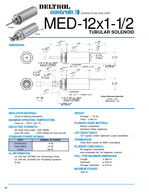
TERMINATION: Vinyl Wire Leads 24 AWG (standard)
PLUNGER CONE ANGLE: 60 degrees (standard) also available flat, 90 degrees, custom
PULL TYPE MAXIMUM DIMENSIONS:
INTERMITTENT DUTY
PULL TYPE UNITS 6 VDC
12 VDC 24 VDC 115 VDC
P/N 53751-80 53751-81* 53751-82* 53751-84
6.2 OHMS 25 OHMS 100 OHMS 2500 OHMS
P/N 53751-86 53751-87* 53751-88* 53751-90
WEIGHT: Plunger – .74 Oz. Total – 2.56 Oz.
PLUNGER GUIDE MATERIAL: Plastic (standard) Stainless Steel (optional)
LIFE EXPECTANCY: 107 Cycles Under Optimum Load Conditions
NOTE: Cold Force @ 25°C (77°F) Coil Temperature. NOTE: Hot Force @ 130°C (266°F) Coil Temperature.
NOTE: Approx. 16 sq. in. Heat Sink Required.
61
*Black Items Are Normally Stocked. *Blue Items Are Non Stock – Minimum Quantity May Be Required.
- 1、下载文档前请自行甄别文档内容的完整性,平台不提供额外的编辑、内容补充、找答案等附加服务。
- 2、"仅部分预览"的文档,不可在线预览部分如存在完整性等问题,可反馈申请退款(可完整预览的文档不适用该条件!)。
- 3、如文档侵犯您的权益,请联系客服反馈,我们会尽快为您处理(人工客服工作时间:9:00-18:30)。
M97系列可编程直流电子负载用户使用手册适用型号M9711/M9712/M9712B/M9712C/M9712B30Maynuo Electronics 2009II版本号:V1.1南京美尔诺电子有限公司版权所有目录第一章简介 (1)第二章技术规格 (2)2.1主要技术规格 (2)2.2电子负载尺寸图 (6)第三章快速入门 (7)3.1开机自检 (7)3.2如果负载不能启动 (8)3.3前面板和后面板介绍 (9)3.4键盘说明 (10)3.5菜单操作 (11)第四章面板操作 (16)4.1基本操作模式 (16)4.1.1定电流操作模式(CC) (16)4.1.1.1标准定电流模式 (16)4.1.1.2加载卸载定电流模式 (17)4.1.1.3软启动定电流模式 (18)4.1.1.4定电流转定电压模式 (19)4.1.2定电阻操作模式(CR) (19)4.1.2.1 标准定电阻模式 (20)4.1.2.2 加载卸载定电阻模式 (20)4.1.2.3定电阻转定电压模式 (21)4.1.3定电压操作模式(CV) (21)4.1.3.1标准定电压模式 (22)4.1.3.2加载卸载定电压模式 (22)4.1.3.3软启动定电压模式 (23)4.1.4定功率操作模式(CW) (24)4.1.4.1标准定功率模式 (24)4.1.4.2加载卸载定功率模式 (25)4.2动态测试操作 (26)4.2.1连续模式(CONTINUOUS ) (26)4.2.2脉冲模式(PULSE) (26)4.2.3触发模式(TRIGGER) (27)4.2.4 动态测试参数设置 (27)4.2.5波形控制 (28)4.2.5.1方波 (28)4.2.5.2三角波 (28)4.2.5.3梯形波 (28)I4.2.6 触发控制 (28)4.2.7 LIST功能 (29)4.2.7.1.编辑LIST列表 (29)4.2.7.2执行LIST功能 (30)4.2.8 自动测试功能 (30)4.2.8.1编辑自动测试列表 (31)4.2.8.2设置自动测试触发输出方式 (32)4.2.8.3执行自动测试功能 (33)4.3输入控制 (33)4.3.1 短路操作(SHORT) (33)4.3.2 输入开关操作 (33)4.4电子负载可操作范围 (34)4.5保护功能 (34)4.5.1 过电压保护(OV) (34)4.5.2 过电流保护(OC) (35)4.5.3 过功率保护(OW) (35)4.5.4 输入极性反接 (36)4.5.5 过温度保护(OH) (36)4.6远端测试功能 (36)4.7蓄电池放电测试操作 (36)4.8快捷方式功能说明 (38)4.9通讯协议 (39)4.9.1 概述 (39)4.9.2 通讯口DB9的定义 (40)4.9.3 选择通讯波特率 (41)4.9.4 数据 (41)4.9.5功能码 (41)4.9.6 差错校验 (41)4.9.7 完整命令帧解析 (42)4.9.8 线圈与寄存器地址分配 (46)4.9.9 命令寄存器CMD定义 (49)4.9.10常用操作功能说明 (50)4.9.11 通讯线的选择 (56)II第一章简介M97系列产品是美尔诺电子公司设计制造的新一代直流电子负载,采用高性能芯片,高速,高精度设计,提供0.1mV,0.01mA的解析度(基本精度为0.03%,基本电流上升速度2.5A/us), 外观新颖,生产工艺科学严谨,相比同类产品,更具性价比。
广泛用于生产线(手机充电器,手机电池,电动车电池,开关电源,线性电源),科研机构,汽车电子,航空航天,船舶,太阳能电池,燃料电池等行业。
主要特点恒流,恒阻,恒压,恒功率,恒流+恒压,恒阻+恒压,六种高速动作模式;过流,过压,过功率,过热,极性反接保护;高亮度,真空,VFD屏,双排,四路同步显示;根据温度变化,无极伺服,智能风扇系统;电路软启动时间设定,可根据设定电压值带载;电池测试及短路功能;提供动态测试,上升下降斜率设定;提供任意波形编辑能力(LIST功能);支持自动测试功能;支持外部触发输入,输出;提供外部电流波形监视端子;支持远端电压补偿,多个数据存储;开机自检,软件校正,标准仪器架设计;支持TTL电平的串行口通讯。
1第二章技术规格2.1 主要技术规格23452.2 电子负载尺寸图第三章快速入门3.1开机自检1. 验货请您在收到负载的同时检查一下是否收到以下各附件,若有任何缺失,请联络距离您最近的经销商。
□一根电源线(符合本地区使用的电压标准)□一本操作手册.(标配)□一张光盘(若您有购买通讯部件)□一张合格证(标配)一套通讯线缆(若您有购买通讯部件)首先用户需要把电源线正确连接并上电,下面是自检的具体步骤。
3.2如果负载不能启动用下面的方法可以帮助来解决在打开负载时您可能遇到的问题。
1)检查电源线是否接好应先检查电源线是否接好,负载是否已经被供电,电源开关是否被打开。
2)检查负载的电源电压设定负载的工作电压为110V或220V两种方式,检查您的负载的电压设置是否和供电电压相匹配。
3)检查负载的保险丝是否烧坏若保险丝烧坏,请您用下表中的保险丝规格来替换。
4).保险丝的更换方法用平口螺丝刀将负载的后面板上电源输入插座下方的小塑料盖打开,就可以看见保险丝,请使用上述规格相符的保险丝。
(保险丝的位置如下图)图3.1 保险丝位置3.3前面板和后面板介绍M97系列电子负载前面板如下图所示图3.2 前面板图①面板的上半部分为黑色VFD显示屏和旋钮②面板的下半部分从左至右依次为0-9数字键和ESC退出键,功能按键,上下移动键和Enter键,输入和输出端子。
M97系列电子负载后面板如下图所示0-满量程电流,对应0-10V 输出,可接示波器,看动态波形远端量测端子,触发输入输出接口多功能通讯接口, RS232, RS485, USB 转接3.4键盘说明321233.5菜单操作按下Shift+Menu键后进入菜单功能,此时VFD上显示出可选择菜单,可使用上下操作键▽和△或旋钮来翻转VFD屏幕,将依序出现以下功能。
此时按下Enter键,将会进入光标所在位置的功能选项,可使用上下操作键▽和△或旋钮来翻转VFD屏幕,按下Enter键就可以进入下一级子菜单。
按Esc键返回上一层菜单。
第四章面板操作4.1基本操作模式电子负载可以工作在下面四种模式中:1. 定电流操作模式(CC).2. 定电压操作模式(CV).3. 定电阻操作模式(CR).4. 定功率操作模式(CW)4.1.1定电流操作模式(CC)在定电流模式下,不管输入电压是否改变,电子负载消耗一个恒定的电流,如下图所示。
请注意,如果待测源能够输出的最大电流值小于设定的定电流值,负载将不能保证调整为设定电流值,待测源电压也可能会被拉低。
ILoad currentLoad voltageV图4.1 定电流模式4.1.1.1标准定电流模式按I-SET按键,负载显示“STANDARD CURR=xxxxxxxxA”,提示当前定电流值,此时可以按面板上的数字键与小数点键,从高位到低位依次输入所需的定电流值,并按Enter键确认,负载进入标准定电流模式。
此时,如果输入状态为OFF,则显示面板右上角显示“OFF”,如果要改变输入状态为ON,请按On/Off 按键,此时显示面板右上角显示“CC”或“Unreg”,显示“CC”表示达到预想的定电流值,显示“Unreg”表示负载无法正确调整到预设电流值,请检查待测源是否正确连接并开启,或者待测源是否能够输出预设定电流值。
此时,如果要微调设定电流值,可以使用右上角的旋转编码器,顺时针调节为增加,逆时针调节为减小,请注意,如果设定电流值已经达到负载设置的最大电流值,则无法向上调节电流值。
此时,在显示面板的右下侧为设定电流值指示,其中一位数字下有光标提示,表示当前微调细度为当前位置的1个单元,如果用户希望改变调节细度,可以下压旋转编码器,旋转编码器包含了一个按键,此按键每被按下一次,提示光标将会移动一格,以此实现调节细度的调整。
4.1.1.2加载卸载定电流模式加载卸载模式是对待测源的一种保护,当待测源电压刚开始爬升时,负载自动调整为开路状态,直到待测源电压爬升到ONSET加载电压之后,才开始带载,负载调整为设定定电流值。
当待测源电压开始跌落,并跌落到OFFSET卸载电压之后,负载自动调整为开路状态。
如果ONSET加载电压值大于OFFSET卸载电压值,负载将可能避免在卸载电压临界点附近频繁的带载卸载,可以更好的保护待测源。
图4.2 加载卸载模式在标准定电流模式下,依次按Shift+1(V_Level)键,进入加载卸载定电流模式,此时负载显示“ONSET VOLT=xxxxxxxxV”提示当前加载电压,此时可以按面板上的数字键与小数点键,从高位到低位依次输入所需的加载电压值,并按Enter键确认,此时负载显示“OFFSET VOLT=xxxxxxxxV”提示当前卸载电压,此时可以按面板上的数字键与小数点键,从高位到低位依次输入所需的卸载电压值,并按Enter键确认,负载进入加载卸载定电流模式。
此时,如果输入状态为OFF ,则显示面板右上角显示“OFF ”,如果要改变输入状态为ON ,请按On/Off 按键,此时显示面板右上角显示“CC_UN ”或“Unreg ”,显示“CC_UN ”表示达到预想的定电流值,显示“Unreg ”表示负载无法正确调整到预设电流值,请检查待测源是否正确连接并开启,电压是否在正常范围内,或者待测源是否能够输出预设定电流值。
此时,在加载卸载定电流模式下,按Shift+1(V_Level )键,负载将会回到标准定电流模式。
4.1.1.3软启动定电流模式软启动定电流模式,等效与一个感性负载,其模拟电感量大小正比于软启动的上升时间长短,在此模式下,待测源将可能避免大电流的瞬间冲击。
Load currentITRising Time图4.3 软启动电流模式在标准定电流模式下,依次按Shift+2(S_Start )键,进入软启动定电流模式,此时负载显示“RISINGTM=xxxxxxxxvmS ”提示当前上升沿时间,此时可以按面板上的数字键与小数点键,从高位到低位依次输入所需的上升沿时间,并按Enter 键确认,负载进入软启动定电流模式。
此时,如果输入状态为OFF ,则显示面板右上角显示“OFF ”,如果要改变输入状态为ON ,请按On/Off 按键,此时显示面板右上角显示“CC_S ”或“Unreg ”,显示“CC_S ”表示达到预想的定电流值,显示“Unreg ”表示负载无法正确调整到预设电流值,请检查待测源是否正确连接并开启,或者待测源是否能够输出预设定电流值。
