空调系统安装操作说明
CZ-64ESMC1U系列空调系统控制器安装说明书
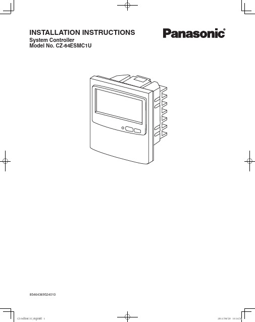
85464369524010INSTALLATION INSTRUCTIONSSystem ControllerModel No. CZ-64ESMC1U2ContentsPageProduct Information ...............................................................................................2Alert Symbols ........................................................................................................2Installation Location ...............................................................................................3Electrical Requirements.........................................................................................3Safety Instructions .................................................................................................31. General ..............................................................................................................42. Installation site selection ....................................................................................43. How to install the system controller . (4)I nstallation procedure ................................................................................5 Electrical Wiring .........................................................................................6 Basic wiring diagram of control wiring .......................................................74. Address switch setting .......................................................................................85. Mode setting ....................................................................................................116. How to perform zone registration (12)ZONE registration table ...........................................................................13(a) Zone registration using the remote controller .........................................14(b) Zone registration using the system controller .........................................15(c) Automatic zone registration using the system controller ............................167. How to check overlapping of central address no. ............................................178. Memory back up switch ...................................................................................189. Test run (18)Product InformationIf you have problems or questions concerning your Air Conditioner, you will need the following information. Model and serial numbers are on the nameplate on the bottom of the cabinet.Model No. ____________________Serial No. ____________________Date of purchase _______________________________________________Dealer’s address _______________________________________________Phone number _______________Alert SymbolsThe following symbols used in this manual, alert you to potentiallydangerous conditions to users, service personnel or the appliance:This symbol refers to a hazard or unsafe practice which can result in severe personal injury or death.This symbol refers to a hazard or unsafe practice which can result in personal injury or product or property damage.CZ-64ESMC1UInstallation LocationWe recommend that this system controller be installed properly by •qualifi ed installation technicians in accordance with the Installation Instructions provided with the system controller.Do not install this system controller where there are fumes or•fl ammable gases, or in an extremely humid space such as agreenhouse.Do not install the system controller where excessively high heat-•generating objects are placed.Electrical Requirements1.All wiring must conform to the local electrical codes. Consult your dealer or aqualifi ed electrician for details.2.Wiring must be done by a qualifi ed electrician.To warm up the system, the power mains must be turned on at least fi ve (5) hours before operation. Leave the power mains ON unless you will not be using this appliance for an extended period.Safety InstructionsRead this booklet carefully before using this system controller. If you •still have any diffi culties or problems, consult your dealer for help.The air conditioner is designed to give you comfortable room•conditions. Use this only for its intended purpose as described in the Operating Instructions.Never touch the unit with wet hands.•Never use or store gasoline or other fl ammable vapor or liquid near •the air conditioner — it is very dangerous.The air conditioner has no ventilator for intaking fresh air from•outdoors. You must open doors or windows frequently when you use gas or oil heating appliances in the same room, which consume a lot of oxygen from the air. Otherwise there is a risk of suffocation in an extreme case.Do not turn the air conditioner on and off from the power mains•switch. Use the ON/OFF operation button.Do not stick anything into the air outlet of the outdoor unit. This is •dangerous because the fan is rotating at high speed.Do not let children play with the air conditioner.•Do not cool or heat the room too much if babies or invalids are•present.341. GeneralThis booklet briefl y outlines where and how to install the system controller. Please read over the entire set of instructions for the indoor and outdoor units and make sure all accessory parts listed are with the controller before beginning.NOTEGive these instructions to the customer after fi nishing the installation.2. Installation site selectionInstall the system controller at a height of between 3 and 5 ft. above the fl oor.• Do not install the system controller in a place where it will be exposed to• direct sunlight or near a window or other place where it will be exposed to the outside air.Be sure to install the system controller vertically, such as on a wall.• 3. How to install the system controllerDo not twist the control wiring together with the power wiring or run it • through the same metal conduit, because this may cause a malfunction.Install the system controller away from sources of electrical noise.• Install a noise fi lter or take other appropriate action if electrical noise • affects the power supply circuit of the unit.Do not supply power to the unit or try to operate it until the tubing and wiring to the outdoor unit is completed.5Installation procedure (1) Remove the fl at-top screw on the bottom of the back case. When you open up the decorative cover, you will see two notches under the controller. Inset a coin or other fl at object into these notches and pry off the back case. (Fig.1)(2) Connect the wires to terminal base of the system controller (see next page).(3) Attach the back case with the 2 screws (1-3/16 in.) provided.(4) T o fi nish, fi t the back tabs of the back case into the system controller and mount it using the flat-top screw.controllerFig. 16Electrical WiringFig. 2DC voltage pulse Photocoupler inputAllowable contact voltage and current: 24 V , 10 mA Pulse width: 300 ms or moreNo-voltage a-contact static outputAllowable contact voltage and current: 30 V , 0.5 AWhen using the T10 cable:(1) Connect B1, B2 to indoor unit 2P terminal base. (*No polarity). Wire size is AWG#W18.(2) Connect B5, B6 to indoor PCB T10 connector using the accessory 6P connector. (with fuse) (*No polarity) T otal wire length is less than 330 ft. and size is AWG#W18.Fig. 3When using the CRV cable:(1) Connect B1, B2 to indoor unit 2P terminal base. (*No polarity). Wire size is AWG#W18.(2) Connect B5, B6 to indoor PCB CRV connector using the accessory 2P connector. (*No polarity)T otal wire length is less than 330 ft. and size is AWG#W18.Fig. 4NOTEConnectors are different depending on the indoor unit PCB. Select the cable according to the indoor unit PCB.Use the T10 cable.Use the CRV cable.T10 connectorT10 cableT10 connectorT10 cableCRV cable Terminals for remote monitoring A1:Input for turning on air conditioners concurrently.A2:Input for turning off air conditioners concurrently.A3:Common input for turning air conditioners on or off.A4:ON operation state indicator output.A5:Alarm indicator output.A6:Common indicator output.Basic wiringB1:Inter-unit control wiring. (Low voltage)B2:To indoor unit 2P terminal base (U1, U2)*No polarityB3:Auxiliary of inter-unit control wiring B4:Not be used B5:Power supply: DC 12 V *No polarity B6:To CRV connector or T10 connector on indoor PCB7Basic wiring diagram of control wiringA max.of 64 indoor units and 30 outdoor units can be connected in 1system.Up to 10 system controllers can be connected in 1 systems.Using Schedule Timer(CZ-ESWC2) with System Controller(CZ-64ESMC1U)• BASIC DIAGRAMCZ-ESWC2CZ-64ESMC1UIt is prohibited to connect the Schedule Timer(CZ-ESWC2) with System Controller(CZ-64ESMC1U) simultaneously.• CZ-ESWC2CZ-64ESMC1U8How to reach the P.C. board Remove the fl at-top screw on the bottom of the back case. When you open up the decorative cover, you will see two notches under the controller. Inset a coin or other fl at object into these notches and pry off the back case. The P .C. board on the back of the controller is now visible.4. Address switch settingDip switchFig. 59*All switches are OFF position at shipment.Fig. 6105. Mode setting According to function of each system controller, setSW1 as Fig. 7.(1) Central control/Remote control modeCentral control modeSystem controller is used as central controlequipment.Individual setting by remote controller can beinhibitted by system controller.Remote control modeSystem controller is used as remote controller.Setting by system controller is inhibitted by othercentral control equipments.(2) ALL/ZONE modeALL modeAll indoor units can be controlled by systemcontroller.ZONE modeIndoor units in one of ZONE 1, 2, 3 or 4 can becontrolled by system controller.(3) Function of system controller is 10 types accordingto combination of central control/remote controlmode and ALL/ZONE mode setting as the table 1.(4) Stick the system controller unit label in aconspicuous position.Fig. 7Table 1Central control Remote control ALL 1. ALL/Central 6. ALL/Remote ZONE1 2. ZONE1/Central7. ZONE1/Remote ZONE2 3. ZONE2/Central8. ZONE2/Remote ZONE3 4. ZONE3/Central9. ZONE3/Remote ZONE4 5. ZONE4/Central10. ZONE4/Remote11126. How to perform zone registrationT o operate the system controller properly, zone registration is required after fi nishing the test run (and after setting all indoor unit addresses) using one of the following methods.(a) Zone registration using the remote controllerRefer to page 14(b) Zone registration using the system controllerRefer to page 15(c) Automatic zone registration using the system controllerRefer to page 16For methods (a) and (b), you should make a zone registration table manually before performing the registration as shown on the page 13.For method (c), zone registration is executed automatically, proceeding from small indoor unit address and small central addresses to larger numbers in numerical order. For example:Central address 123456ZONE-group 1-11-21-31-41-51-6Indoor unit address1-11-22-12-22-33-1NOTE1. An indoor unit address is assigned to each indoor unit during automatic address operation. Each indoor unit address combines an R.C. address and indoor unit number as follows:: Indoor unit address (UNIT No.) Indoor unit No.Refrigerant circuit No. (R.C. address)This address is displayed on remote controller for UNIT No. when the UNIT button is pressed.2. The central address represents the zone and group number. Theseaddressed are assigned in ascending numerical order.ZONE registration tableZONE GROUP CentraladdressIndoor unitaddress(UNIT No.)UnitlocationZONE GROUPCentraladdressIndoor unitaddress(UNIT No.)Unitlocation1113133 22234 33335 44436 55537 66638 77739 88840 99941 10101042 11111143 12121244 13131345 14141446 15151547 161616482117414921825031935142045252155362265472375582485692595710261058112711591228126013291361143014621531156316321664NOTE 1.Assign indoor unit addresses to the desired positions (central addresses)manually.2.For group control, only the main indoor unit should be assigned. Sub indoorunits cannot be assigned.1314(Determination of central address)In this case, after confi rming which indoor unit is connected to the remote controller and that the air conditioner in the OFF state, you set the central addresses one at a time. If the system has no remote controller, connect a remote controller to the system temporarily. Then follow this procedure.NOTEThe indoor unit address must already have been set before performing zone registration. If necessary, refer to the Installation Instructions supplied with the outdoor unit.(1) Press the(3) Once in this mode, the UNIT No., CODE No., No. of SET DATA andindications will fl ash on the display as shown Fig. 8.NOTEIn case of group control “ALL ” instead of “UNIT No.” will flbutton once.NOTEThe CODE No. 03 must be selected to perform zone registration usingthe remote controller.registration table.from flbutton and reset the central address.(7) Press thenish zone registration.For example, in this caseIndoor unit address: 1-8Central address : 17 (ZONE 2, GROUP 1)Fig. 915In this case, you set all Central addresses by system controller at once manually.(1) Press theand CODE No. C1 will fl ash.takes place as Fig. 10.GROUP No. turns ON and UNIT No. (Indoor unit address) changes from fl ashing to ON state. UNIT No. is registered to selected ZONE No. and GROUP No.reselect the ZONE, GROUP and UNIT No.(6) Register the other UNIT No. in the same way by following the steps (3) to (5).fl ashes for a few minutes, then OFF.For example, in the case at left Zone 3, group No. 7Unit No. (indoor unit address) 2-8Unit No. 2-8 is registered to zone 3-group 7.Fig. 10Fig. 1116(c) Automatic zone registration using the system controller(1) Press theseconds. and CODE No. C1 will fl ash.C2 changes from fl ashing to ON state and automatic zoneregistration will start.(3) Registered GROUP No. will be disappeared all.(4) Central address will be assigned from small indoor unit address to large one in numerical order automatically.Finishing automatic zone registration,changes from fl ashing to OFF .registration fi fl ashes for a few minutes, then OFF.Fig. 12177. How to check overlapping of central address no.(1) Press theseconds.and CODE No. C1 will fl ash.C3 changes from flashing to ON state and will fl ash. Then auto. overlap checking will start.(3) If C3 changes from ON to fl ashing and stops fl ashing anddisappears, there is no overlapping.(4) If some of GROUP No., ZONE No. and UNIT No. fl ash, you should try again the zone registration.①② Select the flUNIT No.③ Then fiFig. 13188. Memory back up switchCheck the back up switch is ON for back side of system controller PCB.9. Test run(1) Power on for all indoor units. Next, power on for system controller. will fl ash, checking the indoor unit address automatically.(2) If group No. displayed on system controller is not same as indoor unit No.* which is connected, see Fig. 7 and setting again.*In case of group control, main unit No. only.Back up switchBack up battery19Printed in Japan。
格力 1.5匹 变频中央空调 使用安装说明书
使用安装说明书中静压风管送风式空调器使用前请仔细阅读本说明书,并妥善保管更多使用指引,请扫描“扫码开启服务”二维码目录声明●本产品执行标准:GB/T 18836。
●本说明书仅作示例说明,产品及部件外观请以实物为准。
● 使用前请仔细阅读本说明书及电子说明书,否则可能会给本机造成损害或危及您或他人的人身 财产安全。
由于技术更新,致产品升级或变更,恕不另行通知。
电子说明书也会随技术创新进 行更新,请扫描二维码获取最新电子说明书。
● 阅读后请与发票一起妥善保管。
安全警示空调器主体构件配件清单遥控器使用说明清洁保养安装及维修注意事项环保清单安装简图室内机回风箱进风面板室内机排水管的安装技术参数检验运行使用条件常见现象及故障安装服务、售后服务保修卡安全警示产品简介使用说明清洁保养安装说明服务指南01030304050708131416171919192021封底查阅电子说明书方法● 请扫描说明书封底“扫码开启服务”二维码。
安全警示01提示本节记载了安全事项的重要内容,以防止对使用者及他人造成人身伤害或财产损失。
请在充分理解下面内容(标志、图标)的基础上阅读正文,并请务必遵守所记载的安全事项。
禁止用电源开关直接关闭空调器。
请勿用湿手操作空调器。
禁止用水直接冲淋空调器。
卸下或打开面板时,切勿触碰空调器的金属部位。
不得让身体长时间直接接触冷风或制冷过度。
不得踩踏在室内机、室外机上,或在其上放置物品,避免遮挡进、出风口。
切勿用于食品、精密仪器、贵重美术品的保存,切勿安装在船舶、车辆等特殊场所。
切勿在空调风直接吹到的地方使用燃烧器具,在密闭的房间内使用或与燃烧器具同时使用时,请经常打开窗户通风。
切勿在室内机下面放置其它电气产品、家具、贵重物品等。
禁止擅自更换电源线,或将电源线中途驳接,或与其它电器并联使用;如果电源软线损坏,为了避免危险,必须由制造商、其维修部或类似部门的专业人员更换。
表示【禁止】的内容禁止在空调器使用场所存放易燃易爆气体;不得使用与空调器本身所配制冷剂不同的其它制冷剂。
海信日立空调工程安装操作标准
海信⽇⽴空调⼯程安装操作标准HITACHI青岛海信⽇⽴空调系统有限公司⼯程安装操作标准-SET-FREE -FS3/FS5(R22)系列FSG/FSVG(R407C)系列FSN(R410A)系列主编部门:客户⽀持部⽬录HITACHI (1)青岛海信⽇⽴空调系统有限公司 (1)⼯程安装操作标准 (1)⼀、总则 (1)⼆、安装⼯程的顺序和准备 (2)1、安装⼯作的重要性 (2)2、与其它专业配合 (3)3、安装⼯程的⼀般顺序 (3)4、施⼯图纸审核 (5)5、施⼯组织设计 (5)6、安装⼯具及仪器仪表 (6)要求⼯具齐全、型号标准符合安装及技术要求。
仪器仪表经过检测或鉴定,量程满⾜要求。
(6)7、材料要求 (8)8、管理体系 (8)三、制冷剂管道安装 (8)1、制冷剂配管施⼯概要 (8)2、制冷剂配管的加⼯ (10)3、制冷剂配管安装 (13)4、分歧管的安装 (15)5、管道的吹扫 (15)四、室外机安装 (16)1、到货检查 (16)2、吊装 (17)3、位置选择 (17)4、室外机基础 (17)5、室外机的安装要求 (18)6、室外机的布置间隙 (19)7、室外机的固定与防振 (26)五、室内机安装 (27)1、⼀般要求 (27)2、天花板内置风管式 (27)3、四⾯出风嵌⼊式 (29)4、壁挂型室内机的安装 (31)六、风管制作安装 (32)1、风管制作 (32)2、风管的连接 (32)3、风管的连接 (33)4、风⼝及部件安装 (33)七、冷凝⽔系统 (34)1、管材 (35)2、管道安装要点 (35)3、天花板内置风管式 (35)4、四⾯出风嵌⼊式 (36)5、集中排⽔⽅式 (36)⼋、制冷剂系统 (37)1、⽓密性试验 (38)2、系统的真空⼲燥 (39)3、制冷剂的充填 (39)九、保温 (40)1、制冷系统保温 (40)2、冷凝⽔系统保温 (41)3、风管保温 (41)⼗、电⽓系统与安装 (42)1、设备电源 (42)2、配电系统的敷设 (43)3、室外机的配电参数 (44)4、室内机的配电参数 (45)⼗⼀、控制系统与安装 (46)1、控制线 (46)2、控制器与管理系统的类型、安装要点 (47)3、控制线连接实例 (51)⼗⼆、调试与试运⾏ (52)1、调试前的准备⼯作 (52)2、调试前的检查确认⼯作 (53)3、单机试运转及调试 (53)4、联机试运转及调试 (54)⼗三、竣⼯验收 (56)⼀、总则●为加强安装⼯程质量管理,统⼀空调系统安装⽅法,制定本标准。
空调水系统及其安装

❖ 一、空调水系统的安装
空调水系统安装包括: 冷【热】水、冷却水、凝结水系统的设备、管道及附件的安装施工??
一、管材 空调水系统的管道一般选用:无缝钢管、焊接钢管、镀锌钢管、有机材料管道【硬聚氯乙
烯【PVC-U】、聚丙烯【PP-R】、聚丁烯【PB】、与交联聚乙烯【PEX】】
二、连接 A、镀锌钢管:
及长度每隔一五m设置承重防晃支、吊架??
❖ 一、空调水系统的安装
水平管道支架详图
冷热水管道与支、吊架之间!!应由绝热衬垫【承 压强度能满足管道重量的不燃、难燃硬质绝热材 料或经防腐处理的木衬垫】!!其厚度不应小于绝 热层厚度!!宽度应大于支、吊架支承面的宽度?? 衬垫的表面平整、衬垫接合面的空隙应填实??
一、空调机组的分类 二、空调机组的安装的分类
一】、机组结构分类:柜式和组合!! 二】、安装方式分类:立式、卧式和吊装式??
立柜式空调机组
柜式空调机组!!也叫整体式空调机组!! 是将空气过滤器、表冷器、加热器、 加湿器等空气处理部件!!整体装在一 个立柜式箱体内而形成的机组??
与机组连接的管道应设支架!!其重 量不应由机组承担!!
卧式组合式
一、卷绕式过滤口的安装、框架应平整、滤 料应松紧适当!!上下筒应平行?? 二、消声口、消声弯管应单独设支架!!其重量 不得由风管承受??
组合式空调机组!!也叫装配式空调机组!!由不 同的空气处理段组成!!如新风段、回风混合段加
热段等等??各组成段均按设计参数选用设备组 装而成!!段与段之间可在现场组装
学生互评 每个小组随机抽一名组员上 台点评其它一组的作业??
教师总评 对识图任务和学生互评两 个环节分别做出点评!!加 入奖罚机制??
吊装式
海尔Haier household air conditioner KF-50LW_02RA1-S2 KFRd-72LW_02RA1-S2 安装手册说明书
安全注意事项“警示”标志的内容,有关产品安全和使用者的人身安全,必须严格按警示的内容操作。
尊敬的海尔用户:您好!感谢您使用海尔空调。
为了您能更好的阅读本说明书和使用空调,以下是我们对说明书中出现标志符号的解释说明:尊敬的海尔用户:感谢您选择、使用海尔产品。
该系列空调执行国家标准: GB/T 7725-2004技术数据:安装前准备电力要求◆安装说明室内机安装◆接线方法连机线压线方法接线完成后,必须用压线夹将连机线压紧,压线夹应压在连机线的外护套上。
如右图:加长电源线电源线加长必须使用整根电源线,不得接驳;弱电信号线加长时,接线必须错开100mm,并焊牢。
◆◆室内外机接线图端子的接线方法松开接线螺丝,将连机线端子插到端子排和接线螺丝之间,然后拧紧螺丝,将连机线轻轻向外拉,确认接线端子被压紧。
请用户根据使用说明书来使用空调器试运转的检查项目,在□内打上√号。
安装检查及试运转□ 管子接头是否漏气?□ 管子接头的隔热处理如何?□ 室内外机电气连接是否牢固地插入接线板?□ 室内外机电气连接线固定牢固吗?□ 排水管布置正确吗?□ 接地线连接牢固吗?□ 电源电压符合电气规程吗?□ 务必请安装人员进行一次试运转,并检查各项的运转情况。
□ 控制面板显示正常吗?□ 有无噪音?□ 制冷是否正常?□ 室内温度调节器工作正常吗?□ 电源部分:L 应连接在火线上N 应连接在零线上 应连接在地线上使用保养介绍安装完毕,服务人员应认真向用户讲解使用保养常识,并亲手示范。
◆◆根据选择的室内机安装位置和管路走向,确定打穿墙孔的位置。
1.穿墙孔的定位2.打穿墙孔打一个穿墙孔,外侧稍微向下倾斜。
安装护圈,安装完毕,用石膏粉或油灰封住。
布管时,排水管要放在下面。
排水管要做成斜坡形,途中应避免上凸和下凹情况发生。
如果环境湿度过大,排水软管(特别是室内)必要时要用隔热材料进行缠绕保温处理。
注:当管路加长时,先用系统外制冷剂R22将连机管内的空气排空,再按排气方法排出多余的制冷剂。
空调安装说明书
空调安装说明书空调安装说明书篇一:空调使用说明书中央空调格力送风机组自动控制使用说明书为保证空调机组高效,节能,安全的运行。
请必须按照产品使用说明书运行。
1. 启动风机前a. 请将系统各电源,主控制断路器保持通路状态(此时主控制柜电源指示灯亮起,控制触摸屏电源灯亮起,触摸屏亮起)b. 应检查各个送风机组手动新风阀,送风防火阀是否处于开启状态,如未开启,请手动将阀门打开。
c. 送风机系统有电加热辅助加热系统,冬季运行时应保持电加热器常开状态(注,电加热器内有温控开关,当温度达到指定热量时,加热器会自动关闭加热系统,当温度低于设定温度时,加热器会自动开启)2. 手动启动a. 在控制屏上点击要启动的机组编号,如要启动1#机组,就触摸1#机组按钮,同理2#和3#。
此时控制屏上显示1#机组控制画面b. 在控制屏上点击手动启动/自动启动按钮,将显示状态改成手动启动状态。
此时空调系统进入手动启动模式。
c. 在控制屏上点击新风阀开启按钮,将新风阀打开,此时控制屏上显示新风阀打开。
d. 在控制屏上点击预热阀按钮,将预热阀状态改为开启状态,预热阀开启需要几秒中的时间间隔,(注机组开启时,预热阀必须是开启的,否者可能会严重损坏机组)e. 在控制屏上点击加热阀按钮,将加热阀状态改为开启状态,加热阀开启需要几秒中的时间间隔,(注机组开启时,加热阀必须是开启的,否者可能会严重损坏机组)f. 启动风机,点击风机启动按钮,将启动状态栏状态改为启动状态,此时风机启动。
3. 自动启动a. 在控制屏上点击对应要启动风机编号,此时屏幕上显示要启动风机控制版面。
b. 在控制屏上点击手动控制/自动控制一栏,点击自动控制按钮。
此时机组进入自动控制状态。
c. 在控制屏上点击自动启动按钮,此时机组自动启动(注,自动启动顺序,新风阀开启—预热阀开启—加热阀开启—风机启动)4. 注意事项a. 此空调设备具有恒温功能,当机组温度达到要求时,机组会相应动作,关闭机组预热阀,减少机组供热量。
拆分式空调系统安装与维护指南说明书
NOTE:Read the entire instruction manual before starting the installation.This symbol →indicates a change since last issue.SAFETY CONSIDERATIONSInstalling and servicing split system equipment can be hazardous due to system pressure and electrical components.Only trained personnel should install or service split system equipment.Untrained personnel can perform basic maintenance functions,such as cleaning coils,and cleaning and replacing filters.All other operations should be performed by trained service personnel.When working on split system equipment,observe precautions in the literature,and on tags and labels attached to the unit.Follow all safety codes.Wear safety glasses and work e a quenching cloth for brazing operations.Have a fire extinguisher available.WARNING:When making flare connections,use one of the flare gaskets provided in the kit to ensure a leak-tight refrigerant e a backup wrench to avoid breaking connection or splitting flare.NOTE:The liquid-and vapor-service valves are located outside of the unit at the rear.The smaller valve is the liquid-service valve;the larger valve is the vapor-service valve.PROCEDURE 1—HIGH-PRESSURE SWITCH INSTALLATION (FOR PROTECTION IN COOLING ONLY)Refer to Fig.1and proceed as follows to install the high-pressure switch.NOTE:Make sure the liquid-service valve is in the fully back seated (counterclockwise)position before installation (Back seating service valves have no valve core in the service port).NOTE:When installing both high-and low-pressure switches on liquid-service valve,connect second tee to service fitting of first tee.1.Remove knockout in service panel next to service valves.2.Carefully uncoil extender tube;tube must not be kinked.Securely connect extender tube flare nut to side of adapter tee without valve core.3.Route extender tube completely through knockout so that tee can be attached to liquid-service valve later.4.Securely connect pressure switch flare nut to male flare fitting on extender tube inside unit.(Using backup wrench,torque to 140in.lb.)5.Remove seal cap from service fitting on liquid-service valve and securely connect to remaining male flare fitting on adapter tee.6.Securely connect flare nut on adapter tee to service fitting on liquid-service valve.7.On back seating valves,remove liquid-service valve stem cap and open valve 3/4turn.Installation InstructionKSAHI0101HPS KHAHI0101HPS High-Pressure Switch Kit Form:AG-SAHI-04Cancels:AG-SAHI-03Printed in U.S.A.10-99Catalog No.63SA-HI1→8.Replace liquid-service valve stem cap fingertight and further tighten cap1/12turn.9.Check all refrigerant connections for leaks and repair if necessary.PROCEDURE2—HIGH-PRESSURE SWITCH INSTALLATION(FOR PROTECTION IN BOTH HEATING AND COOLING MODES)Refer to Fig.2and proceed as follows to install the high-pressure switch.NOTE:When installing the pressure switch adaptor to a previously installed unit,the unit must be pumped down and the field-installed liquid line disconnected.Refer to Pumpdown Procedure in the Split System Residential Air Conditioning and Heat Pump Service Manual.1.Remove knockout in service panel next to liquid-service valve.2.Partially straighten3/16-in.OD tube portion and route flare fitting end through knockout hole.3.Securely connect pressure switch flare nut to male flare fitting on3/16-in.OD tube inside unit.(Using backup wrench,torque to140in.lb.)4.Remove sweat adapter from field liquid line fitting on service fitting on liquid-service valve and securely connect3/8-in.tube portion ofpressure switch adaptor.5.Braze interconnecting liquid line to belled end of pressure switch adaptor.CAUTION:PROCEDURE 3—ELECTRICAL CONNECTION(See Fig.3for Heat Pump and Fig.4for Air Conditioner.)NOTE:In some instances it may be necessary to clip the quick-connect terminals from the wire leads and strip the insulation from the end of the lead to make an electrical connection.Wirenuts have been provided for this purpose.1.Locate unit contactor coil terminals or,if equipped,compressor time delay terminal T1.2.On units without compressor time delay,make electrical connections as follows:a.One pressure switch in unit:Cut Y lead approximately 4in.from contactor coil terminal.Connect 1pressure switch lead to 1cut lead.Connect other pressure switch lead to other cut lead.b.Both high-and low-pressure switches in unit:Cut Y lead approximately 4in.from contactor coil terminal.Connect 1high pressure switch lead to 1cut lead,then connect other high-pressure lead to 1low-pressure lead.Connect remaining low-pressure lead to other cut lead.3.On units with compressor time delay,make electrical connections as follows:a.One pressure switch in unit:Cut wire leading to T1on time delay board.Connect 1pressure switch lead to 1cut lead.Connect other pressure switch lead to other cut lead.b.Both high-and low-pressure switches in unit:Cut wire leading to T1on time delay board.Connect 1high-pressure lead to 1cut lead,then connect other high-pressure lead to 1low-pressure lead.Connect remaining low-pressure lead to other cut lead.4.Restore power and check unit operation.Fig.3—Heat Pump Electrical Connections A95308* T2 NOT USED ON CIRCUIT BOARDSWITHOUT TIME DELAY. WHEN T2 IS NOTAVAILABLE, CONNECT PRESSURE SWITCHESBETWEEN "Y" AND CONTACTOR COIL.C T2T1YCIRCUIT BOARD CONTACTOR *LPSHPSCFig.4—Air Conditioner Electrical ConnectionsA95309—3—SERVICE TRAININGPackaged Service Training programs are an excellent way to increase yourknowledge of the equipment discussed in this manual, including:• Unit Familiarization • Maintenance• Installation Overview • Operating SequenceA large selection of product, theory, and skills programs is available, using popularvideo-based formats and materials. All include video and/or slides, plus companionbook.Classroom Service Training plus "hands-on" the products in our labs can meanincreased confidence that really pays dividends in faster troubleshooting, fewercallbacks. Course descriptions and schedules are in our catalog.CALL FOR FREE CATALOG 1-800-962-9212[ ] Packaged Service Training [ ] Classroom Service TrainingA94328©1999CAC/BDP P.O.Box70,Indianapolis,IN46206agsahi04—4—Book/Tab:1/3a,4/2a Catalog No.63SA-HI1。
海信空调使用安装说明书

注 : 遥控器每隔一定时间向空调器发出一次信号。 如果来自遥控器的信号因为遥控器遗失或者其它 原因而停止10分钟以上,会导致以下情况:
空调器将自动改用装于室内机上的温度传感 器来检测室温,遇此情况时,遥控器周围的温度 可能与在室内机所检测到的温度略有不同;
08
拉下滑盖
温度传感器 发射器
Composition of the air conditioner
空调组成
液晶显示器
遥控器具有温度测试、显示功能。在一般 状况下,空调器对室内温度的调节是以遥控器 测得的温度为依据(具体内容参见下页)。
高效功能按钮
风速选择按钮 方式选择按钮 双模切换按钮 时钟调节按钮 风向调节按钮
静音按钮
空调器强制低风运行。(只在制热、制冷、送风模式下有此功能)
高效功能按钮
1.按下高效按钮,空调器以最大功率运行;15分钟后自动恢复原运行状态;
风速调节按钮 方式选择按钮
按本按钮可以使空调的送风状态在自动、高速、中速、低速之间切换。“ ”:空调器自动选择风速。 “ ”:高速。“ ”:中速。“ ”:低速。
( 10 ) 定时
定时开机
ON
定时关机
OFF
( 11 ) 双模切换(节能运行时显示 该图标, 舒适运行时不显示)
( 12 ) 高效运行
( 13 ) 睡眠运行
睡眠模式1
睡眠模式2
睡眠模式3
睡眠模式4
( 14 ) 并用节电
( 15 ) 取消人机对话
Features
本机特点
[I D M智 能 双 模 控 制]
双模集成设计分为舒适运行模式和节能运 行模式,可以使用双模切换键自由切换。 IDM节能模式是针对用户“短时间运行, 同时不要求快速制冷制热”的需求而设计 的更为高效节能的运转模式。 IDM舒适模式:压缩机高速运转主要实现 短时间内快速制冷制热功能,压缩机大 部分时间运行于低频部分,室温稳定在 设定温度。
格力双系统户式中央空调安装使用说明书
目录一、系统介绍 -------------------------------------------------------------------- 2二、机组介绍 -------------------------------------------------------------------- 31.机组性能 ---------------------------------------------------------------------------------------- 3 2.机组外形示意图 ------------------------------------------------------------------------------- 4三、控制器操作说明 ----------------------------------------------------------- 7A.手操器显示功能------------------------------------------------------------------------------- 7 B.手操器按键功能 ----------------------------------------------------------------------------- 8 C.蜂鸣器------------------------------------------------------------------------------------------- 8 D.基本操作---------------------------------------------------------------------------------------- 8 E.故障代码表 ------------------------------------------------------------------------------------- 9四、日常操作与维护 --------------------------------------------------------- 10五、常见故障及解决方法---------------------------------------------------- 11六、末端设备选型指导------------------------------------------------------- 12七、系统安装 ------------------------------------------------------------------ 131.机组安装 -------------------------------------------------------------------------------------- 13 2.机组接线 -------------------------------------------------------------------------------------- 15 3.末端设备安装 -------------------------------------------------------------------------------- 16 4.水管路连接 ----------------------------------------------------------------------------------- 175.冬季防冻注意事项 -------------------------------------------------------------------------- 18八、系统调试 ------------------------------------------------------------------ 191.空调系统冷冻水的充注 -------------------------------------------------------------------- 19 2.试运转前的检查 ----------------------------------------------------------------------------- 19 3.试运行 ----------------------------------------------------------------------------------------- 19九、随机附件使用说明------------------------------------------------------- 20尊敬的用户:欢迎您选用格力双系统户式(别墅)中央空调机组。
海信空调使用安装说明书
海信空调使用安装说明书变频专家创新就是生活使用安装说明书分体热泵型挂壁式变频分体热泵型挂壁式变频房间空调器房间空调器本机特点..............................2注意事项............................3-7空调组成...........................8-11操作向导..........................12-16维护与清洁...........................17故障对策.............................18制冷剂循环图.........................19产品安装说明......................夹页1产品主要规格......................夹页2KFR-26GW/27Bp KFR-32GW/27Bp KFR-35GW/27Bp青岛海信空调有限公司***** AIR-*****ONER CO.,LTD尊敬的Hisense用户:欢迎您购买、使用海信牌空调器,并感谢您对我公司的信任!我们愿以竭诚的服务,为您创造一个舒适、健康的生活空间。
希望您对我们的工作提出宝贵意见。
在使用之前,请仔细阅读本说明书。
在阅读之后,请妥善保管本说明书。
注:说明书内容如有更改,恕不另行通知,请谅解!本机特点Features[微电脑控制]内置的微电脑功能强大。
遥控器操作简单,易于使用。
空调器可以调节室内温度、湿度,无需您劳神,为您提供一个舒适的空间。
[自动及3级风速]室内风速可设定于自动/高/中/低四种状态。
自[睡眠节能功能][12小时开/关机定时器]定时器可以预约12小时定时开关空调器。
11 10 9 8 7 6 5 12 1 2 3 4此功能能够科学的改变房间温度设定,在保证给您提供舒适的房间环境的前提下,有效的为您节省电力。
[强力除湿]除去潮湿空气中多余的水分,给您以凉快干爽的感觉。
海信空调使用安装说明书

联机配管
注意
请避免在室内机附近 1 米范围内使用如手提电话等无线电装
置,有些无线电装置有可能导致空调器误动作。如果发生故障时,请
切断电源,并且试着在几分钟之后重新启动空调器。
出风口
高效指示
频率指示
定时指示
室内温度指示
睡眠指示 遥控接收窗
高效指示
空调器高频率运行时显示。
温度指示
空调运行时可以显示室内环境温度或设定温度。
频率指示
开机后,频率段会以很慢的速度旋转,随着压缩机运行 频率提高,转速也会提高。
睡眠运行
睡眠运行时显示。
定时指示 遥控接收窗
当使用定时功能时显示。 本部分接收遥控器发射的红外线信号。
注: 1、特殊情况下,室内温度可能显示为“--”图标。 2、在运行中同时按下定时开/关按钮,关闭背光,操作遥控器任意按钮,显示屏 都会点亮3秒后自动关闭。
请不要将手指或其他异物插入室内机、室外机的进风口和出风口, 由于空调器在运转过程中,内部风扇高速旋转,一旦手指或其他异物伸入,不但会影响空调器的正常 运转、导致故障,还会对人身造成伤害。
在拔插电源插头时,请先将电源关闭, 否则,可能会导致打火、触电、火灾等事故的发生。
禁止使用铜线等金属导线替代安全保险丝, 否则,可能会导致火灾事故的发生。
在空调器出风口前不要放置家用电器和其他电气设备, 如果空调器室内机排水不畅冷凝水溢出,或室内机导风叶片表面产生的冷凝水滴落,会造成您财产 的损失,同时也会导致用电设备的短路、漏电、火灾等事故的发生。
清洁、清理空调器时,请先停止空调器的运转,然后拔下电源插头, 否则,可能影响空调器的运转以及造成故障。
在有雷或闪电的情况下,请先停止空调器的运转,然后拔下电源插头(或者将空调器供电线路中的空 气 开 关 置 于O F F位 置 ) , 否则,可能会导致空调器电子器件损坏。
空调安装工程施工(3篇)
第1篇一、工程概述空调安装工程施工是一项综合性较强的工程,主要包括空调设备的采购、运输、安装、调试、验收等环节。
本文将以家用中央空调安装工程为例,详细介绍空调安装工程施工的流程和注意事项。
二、施工准备1. 施工图纸及资料:熟悉施工图纸,了解空调系统的组成、布局、设备型号等;收集相关资料,如设备说明书、安装规范等。
2. 人员配置:组建专业施工队伍,包括空调安装工程师、电工、焊工、安装工等。
3. 施工工具:准备空调安装所需的工具,如扳手、螺丝刀、切割机、焊机、水平尺等。
4. 材料准备:根据施工图纸及设备清单,准备空调设备、管道、配件、保温材料等。
三、施工流程1. 施工现场检查:对施工现场进行实地勘察,确认施工条件是否满足要求,如楼层高度、承重能力、水电线路等。
2. 设备运输及卸货:将空调设备运输至施工现场,并按照要求进行卸货。
3. 室内机安装:(1)确定安装位置:根据设计图纸和用户需求,确定室内机安装位置,确保安装位置符合要求。
(2)吊装:采用吊装设备将室内机吊至安装位置,注意保护设备。
(3)管道连接:将室内机与室外机之间的管道、冷凝水管、信号线等连接好。
4. 室外机安装:(1)确定安装位置:根据设计图纸和现场条件,确定室外机安装位置。
(2)基础施工:为室外机搭建基础,确保基础稳固。
(3)设备安装:将室外机安装在基础上,连接管道、冷凝水管、信号线等。
5. 系统调试:启动空调系统,进行调试,确保系统运行正常。
6. 验收:完成安装调试后,组织验收,确保空调系统符合设计要求。
四、注意事项1. 施工过程中,严格遵循施工规范和操作规程,确保施工质量。
2. 注意施工现场的安全,做好安全防护措施。
3. 严格按照设计图纸和设备说明书进行安装,确保系统性能。
4. 在安装过程中,做好施工记录,为后期维护提供依据。
5. 安装完成后,对系统进行试运行,确保系统运行稳定。
总之,空调安装工程施工是一项重要的工程,施工过程中要注重细节,确保施工质量,为用户提供舒适的居住环境。
中央空调安装流程及规范
中央空调安装流程及规范话说中央空调3分品质7分安装真不为过,中央空调因为它要和室内装修配合得当,实际上设备本身只是一个“半成品”,要使一套家用中央空调能够正常运行,设计、安装、施工的重要性不亚于空调设备的品质。
下面介绍中央空调安装流程,公布如下也方便各位同学参照监督。
安装阶段篇:中央空调要经过3次安装中央空调要提前在装修准备阶段就规划好,事先确定好内机安装位置,而且需预排好所需使用的强电线,一般在水电工进场后即可安排厂家上门安装,正规的安装要第一次安装[水电进场时联系安装]①吊装中央空调室内机,并对内机进行包裹,避免有灰尘杂质进入;②安装排管:冷媒管、冷凝水管、信号线。
第二次安装[第一次安装结束24小时之后]①吊装中央空调室外机;②充填冷媒,测试中央空调系统,测量风口尺寸和位置。
第三次安装[第二次安装结束后或次日]安装风口,最后设备运行测试.安装材料篇:5种关键辅材不可疏忽大意①冷媒铜管中央空调的冷媒运行情况直接决定使用效果,所以冷媒铜管的好坏至关重要。
传统的R22冷媒(氟利昂)的管内压力一般为20公斤左右,而R410新冷媒,管内压力达到了36公斤.因此使用新冷媒的中央空调需要选择更为优质的冷媒铜管。
提醒:用挤压工艺生产的铜管(俗称挤压管),这种管材壁厚均匀,可承受较高压力。
而市场上常见的另一种铜管利用拉伸工艺生产(俗称拉伸管)很容易壁厚不均匀,这对冷媒系统的安全埋下隐患。
②铜管保温:冷媒运行情况直接决定使用效果,铜管保温不可忽视。
③冷凝水管:冷凝水管隐藏在吊顶中,最后会封闭起来.虽然其质量的好坏虽然不会营销空调使用效果,但是一旦其漏水,后果很严重的,必须通过拆除部分或全部吊顶乃至敲墙撬地板(砖)来进行维修.④风口:小部位往往被很多消费者疏忽,但这部分影响使用感受。
常见风口有两种材料:一种是ABS风口,另一种是铝合金风口。
两种风口各有利弊。
ABS风口,采用ABS工程材料制作,不容易结露。
但该材料有一定的热胀冷缩系数,所以在使用过程有可能发出吱吱声,冬天气温低风口也可能产生轻微的拱起。
空调系统安装

空调系统安装空调系统安装是为了提供舒适的室内温度和空气质量,适应各种场所和需求的需要。
本文将详细介绍空调系统安装的过程和注意事项,并提供一些相关的技术知识,以帮助读者更好地了解和实施空调系统的安装工作。
一、准备工作在进行空调系统安装之前,需要进行一些必要的准备工作,以确保安装的顺利进行。
首先,需要明确安装的区域和场所,确定安装空调系统的需要和要求。
其次,需要了解空调系统的种类和性能指标,选择适合的空调系统。
最后,需要准备必要的工具和材料,如螺丝刀、电缆、管道等。
二、空调系统安装步骤1. 定位和安装支架首先,根据设计图纸和安装要求,确定空调室内机和室外机的安装位置。
然后,在墙面、顶棚或地面上安装相应的支架,确保支架牢固稳定。
2. 安装室内机和室外机将室内机和室外机分别安装到相应的支架上。
在安装室内机时,需要保证室内机与墙面保持一定距离,以便维修和清洁。
而安装室外机时,需要考虑通风和排水的问题,避免影响周围环境和使用效果。
3. 连接管道和电缆根据设计图纸和安装要求,连接室内机和室外机之间的冷媒管道和电缆。
在连接管道时,需要注意管道的密封性和稳定性,避免漏水和震动。
同时,还需要确保电缆的安全性和有效性,以保证空调系统的正常运行。
4. 安装空调控制器根据厂商提供的说明书,安装和连接空调控制器,以实现对空调系统的远程控制和调节。
在安装空调控制器时,需要注意接线的正确性和稳定性,以免影响控制器的正常工作。
5. 系统调试和检测安装完成后,需要对空调系统进行调试和检测,以确保系统的正常运行。
首先,进行电气接线和连接管道的检查,确保没有松动和漏气。
接下来,对空调系统进行性能测试,包括制冷效果、温度控制和噪音水平等方面的测试。
三、空调系统安装注意事项1. 安全第一在进行空调系统安装过程中,安全是首要考虑的因素。
安装人员需要佩戴防护设备,如手套、口罩和护目镜,并遵循相关的安全操作规程,以避免事故和伤害的发生。
2. 严格按照说明书和规范操作空调系统的安装需要严格按照厂商提供的说明书和相关规范进行操作。
海信空调使用安装说明书
温湿切换按钮
按本按钮,调节空调器在“温度设定界面”与“湿度设定界面”之间切换。(本系列机型无此功能)
除湿选择按钮
在除湿运行模式下按动本按钮可以进行除湿子模式A( )、B( )、C( )、自动除湿( )的循环 选择。(本系列机型无此功能)
显示切换功能按钮 控制室内显示在设定温度、室内温度、室外温度之间切换
海 信 空 调 变 频 专 家
使用安装说明书
分体热泵型挂壁式变频 房间空调器
KFR-26GW/08FZBpJ KFR-35GW/08FZBpJ KFR-26GW/09FZBpJ KFR-35GW/09FZBpJ KFR-26GW/27FZBpHJ KFR-35GW/27FZBpHJ
或霜冻等的情况下,显示的室外温度也可能与实际的室外温度有偏差。
2、特殊情况下,室内、室外温度可能显示为“---”图标。在首次通电压缩机未
启动等情况下,室外温度显示为“---”图标。
3、在运行中使用亮度按钮,关闭亮度,操作遥控器任意按钮,显示屏都会点亮 一段时间后关闭。
KFR-26GW/08FZBpJ
10
液晶显示屏内容介绍
3.遥控器液晶显示面板介绍
当选定某一运行方式时, 只是对应标志符号出现
发送信号时出现
风向显示
风速显示 静音显示 定时开机设定时出现
定时关机设定时出现
标记含义
( 1 ) 运行方式 自动 制热 制冷 送风 自动除湿
( 2 ) 除湿选择 除湿模式A 除湿模式B 除湿模式C
( 3 ) 发送信号 ( 9 ) 设定极限标志
定时开按钮
按本按钮,启动定时开机功能。
定时关按钮 睡眠功能按钮
按本按钮,启动定时关机功能。 按本按钮,可以启动空调器睡眠运行功能。(只在制热、制冷、除湿模式下有此功能)
中央空调安装流程
中央空调安装流程中央空调安装流程导语:家装来说隐蔽工程除了水电,还有就是中央空调,而中央空调三分品质,七分安装;安装的材料和工艺技术非常多种,可以说每个师傅都有每个师傅的方法,从开始的中央空调设计,方案配置,与设计师/业主沟通配合确定定位图纸,再到进唱始安装。
中央空调在安装的时候很大一部分的程度决定了你以后使用的体验。
以下是小编整理中央空调安装流程的资料,欢迎阅读参考。
现将中央空调安装步骤汇总如下:1、内机安装施工队进场第一步就是吊装内机,这里只要注意2个点就可以避免后续问题。
① 内机离房顶距离不得小于1公分,避免机器运行时与墙顶产生共振。
② 内机吊装需考虑百分之一的坡度,接冷凝水的一侧要稍微低一些,避免冷凝水排不出去。
标准流程:安装师傅进场按照图纸现场再核对(机型,定位图纸)排水位置,必须就进排水优先。
再安装吊码定位:要求每90-100CM之间必须两个吊码,以确保冷凝管道的横平竖直。
必须用厚不锈钢吊码,90-100CM之间必须两个吊码固定,彩色管卡颜色区分,气管,液管,冷凝水管,粘贴警示标签,为后面工种施工人员更好的施工。
2、冷媒铜管的安装安装完内机即可安装冷媒铜管,这是中央空调安装过程中最重要的一个环节。
① 所有的.焊接点应该是铜管与分歧管的连接处进行焊接,不存在铜管与铜管焊接。
要求必须用专用分歧管:要求分歧管后至少50CM 才能转弯。
② 在焊接过程中必须在铜管内冲入氮气(充氮焊接工艺),这使铜管内部没有空气避免了产生焊接使内壁结炭从而在正式运转时入压缩机而产生故障。
③ 焊接完成后应该用高压氮气进行管内吹灰,保持铜管内清洁。
3、充氮保压这是焊接完成后必须对铜管进行的压力测试,往铜管内充入一定压力的氮气进行保压,一般压力测试时间为24小时,南京胜出环境工程公司规定压力测试时间至少48小时,一般一个星期;确保铜管丝毫不泄露。
需要特别说明:使用R410冷媒,需保持管内压力为40公斤,R22冷媒则需要保持管内压力为20公斤。
窗式房间空调操作和安装手册说明书
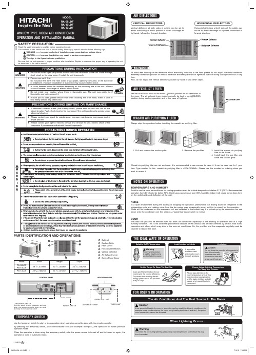
The contents of this section are vital to ensure safety. Please pay special attention to the following sign.WARNING ........ Incorrect methods of installation may cause death or serious injury.CAUTION ......... Improper installation may result in serious consequence.Be sure that the unit operates in proper condition after installation. Explain to customer the proper way of operating the unitPRECAUTIONS DURING INSTALLATIONed technician for the installation of the unit. Water leakage,Do not place the earth line near water or gas pipes, lightning-conductor, or the earth line of telephone. Improper installation of earth line may cause electric shock.PARTS IDENTIFICATION AND OPERATIONS1 Cabinet2 Suction Grille3 Front Cover4 Horizontal De fl ectors5 Vertical De fl ector6 Air Exhaust Lever 7Switch Panel CoverModel RA-08LDF RA-10LDF RA-13LDFWidth 18 1⁄2”, 470mm 22 3⁄64”, 560mmHeight 13 1⁄2”, 345mm 14 3⁄4”, 375mmDepth 253⁄16”, 640mm 27 29⁄32”, 709mmCONTROL PANELINDICATION LAMPTEMPORARY SWITCHUse the temporary switch for start or stop operation when operation cannot be done with the remote controller.By pressing the temporary switch, [use non-conductor stick (for example: toothpick),] the operation will follow previous operation mode.When the operation is done using the temporary switch, after the power source is turned off and is turned on again, the operation is done in automatic mode.AIR DEFLECTORSVertical de fl ectors at both sides of outlets can be set to either auto-swing or static position to direct discharge air rightward, leftward or forward direction.Horizontal de fl ectors at both sides of the outlets can be set to direct discharge air upward, downward or forward direction.VERTICAL DEFLECTORSHORIZONTAL DEFLECTORSTo avoid dew forming on the de fl ectors which eventually may drip to the fl oor, please do not adjust horizontal de flectors extremely downward position or vertical defl ectors extremely leftward or rightward position during cool operation for a long time.Also, do not adjust the vertical de fl ectors position by hand or any other object.AIR EXHAUST LEVERWASABI AIR PURIFYING FILTERSet the air exhaust lever to the down (NOTES ON OPERATIONTEMPERATURE AND HUMIDITYAvoid to use the room air conditioner for cooling operation when the outside temperature is below 21°C (70°F). Recommended operation humidity should be below 80%. Continuous operation at over 80% humidity (indoor) will cause some dews form on the outlet grille and de fl ectors of the unit.NOISEIn a quiet environment during the starting or stopping the operation, phenomena like fl owing sound of refrigerant in therefrigerating cycle and rubbing noise from the fan casing may occasionally occur, but this is normal for the operation.Water will be condensed on the evaporator coil and collected in the bottom tray, it is picked up by the condenser fan and blown onto the condenser coil, this creates a “splashing” sound which is normal.ODORThe odor will possibly be emitted from the room air conditioner especially at the starting of operation and in a high humidity condition. This is not abnormal phenomena because of the various kind of odors emitted by smoke, food stuffs, cosmetics and others which may stick to the room air conditioner. So, the pre-fi lter and the evaporator regularly must be cleaned to reduce the odor.THE IDEAL WAYS OF OPERATIONFOR USER’S INFORMATION<IA890: B >TEMPORARY SWITCHUse this switch to start operation and stop when the remote controller does not work. Normally do not use this switchDEHUMIDIFY LAMPOPERATION LAMPTIMER LAMP1. Pull and remove the suction grille2. Remove the pre-fi lter3. Install the wasabi air purifyingfi lter in the frame4. Install back the pre-fi lter and close the suction grilleWasabi air purifying fi lter are not washable. It is recommended to use vacuum to clean it. It can be used use for 1 year time. Type number for this wasabi air purifying fi lter is <SPX-CFH9W>. Please use this number for ordering when you want to renew it.Never use hot water above 50°C, erosive chemicals or brush to clean the front cover and suction grille because they will damage the plastic surface.● The installation material must be corrosion proof, especially the air conditioner is installed near the sea or hot spring.● Do not install air conditioner in the places where there is a possibility of in fl ammable gas leaks.● Secure tightly the cabinet with screws to the frame. Otherwise there may be danger of the air conditioner dropping.●Please keep the recommended installation dimensions. Otherwise waterdrops or malfunction may occur.●Check the capacity of wiring and power outlet. The power outlet should be used exclusively for the air conditioner. Do not use it with other appliances. Any wiring must follow the national wiring regulation.● Ground the air conditioner to prevent danger of electric shock.● Connect the air conditioner with power source securely.● Use a fuse as below:2 Remove the stopper at front left side of base. (RA-13LDF)DRAIN PANDrain Pan edge shall not exceed the cabinet roller.!CAUTIONS7RS 9LHZINSTALLATION WORK INSPECTION CHECK LISTCAUTIONWhen using the operation of auto swing function, Please manually turn the vertical de fl ector to the utmost right angle before switching on the auto swing function.An abnormal sound will occur when adjusting the vertical de fl ector before switching on the auto swing. This abnormality does not affect the operation.It there is any abnormalities in the vertical movement during the auto swing operation, please do the above setting again.When raining, rain water will enter the outdoor side. An abnormal sound will occur during operation of unit in raining conditions and approximately 10 minutes after rain stop. This will not affect the performance or liability of the room air conditioner.MEMO..................................................................................................................................................................................................... ..................................................................................................................................................................................................... .....................................................................................................................................................................................................Model RA-08LDF RA-10LDF RA-13LDFa 365395* Recommended dimension for performance testing purpose only.b 490580c Over 200Over 200dOver100eOver 1200fOver 150gOver 900hOver 200iOver 200j*130 or more160 or moreDimension (mm)Recommended temperature range for safety testing should be as below:Cold side : Dry bulb 21 – 32°C Wet bulb 15 – 23°CHot side : Dry bulb 21 – 43°CWet bulb15 – 26°C<IA890: B >PRE-FILTERIf the pre-fi lter is clogged with dust, the air fl increased operating noise. Be sure to clean the fi lter about every 20 days. 1 Remove the suction grille by pulling the bottom corner and slightly lift up thesuction grille. 2 - 3 Pull downward to unhook the suction grille and remove the suction grille.● Lift and unhook the bottom of the pre-fi lter and remove it.● Remove dust from the pre-filter by using a vacuum cleaner. If the pre-fi lter is very dirty, wash it with detergent and rinse properly with water. Dry the pre-fi lter with soft cloth and do not expose it to heat or under direct sunlight. ● Install the pre-fi lter by fi tting the top hooks and then hook the bottom ofthe pre-fi lter. ● Attach the suction grille back to its place by hooking at the top side to the front cover, then gently push at bottom corner.Clean the front cover and suction grille with a soft dry cloth. When it is excessively dirty, wipe it with a soft cloth dampened with mild soap, then wipe it again thoroughly with a soft dry cloth.The suction grille can also be removed and be washed with water and mild soap. Remove the suction grille in the following manner.1 Remove the suction grille by pulling the bottom cornerand slightly lift up the suction grille . 2 - 3 Pull downward to unhook the suction grille and removethe suction grille.Does not operate at allPoor cooling performanceCheck the following items before asking for service. If the malfunction persists, please contact service centre.1 Is the power cord loosened or unplugged?2Is the fuse blown out or the circuit breaker tripped? 3 Is the voltage normal?4 Is the main switch set to “OFF” position?1Is the pre-fi lter covered with heavy dust? Clean pre-fi lter and replace it.2 Is the temperature setting correctly?3 Is the sunlight fall directly in the air conditioner?4 Is the air fl ow on the rear side (outdoor) blocked?Leave a space of 900 mm (3 feet) behind the rear side of air conditioner.5 The doors or windows may be opened widely or there are other sources of heat inthe room.6 Is the ventilation damper opened?SymptomCheckRemove all the shipping parts before installation and consult an authorised dealer concerning installation requirements, otherwise may damage the air conditioner.LOCATION● Select a location that can support the weight of the air conditioner and will not cause increased operating noise andvibration.● Select a location to avoid direct sunlight on the air conditioner.● Select a good location for ef fi cient air circulation.●Select a location where there is no obstacles near the air inlet and outlet.INSTALLATION INSTRUCTIONS1 Remove the rubber plug from the base pan.2 Install the drain pan by using 2 pieces of screws (provided) at the cabinet.3Connect the drain pan with the drain hose to drain point. (Drain hose or tubing can be purchase locally. Drain hose inner diameter should be around ø13mm or 1/2 inch.)4 Pour 2 glasses of water into the drain pan to ensure the drainage is functioningnormal.5 Slide the air conditioner unit back into the cabinet.CONDENSED WATER DRAINAGEsurface for maximum cooling ef fi ciency, thus producing a splashing sound.the following procedure which may, reduce the cooling operation performance.Have you removed the shipping parts? Please check the caution sheet which is attached at front cover.Is the incline of room air conditioner regarding front and rear, right and left all right after installation?Is the strength of installation suf fi cient?Have you grounded the room air conditioner?Have you fastened the unit to the cabinet?Have you done a test operation, and are there any abnormal phenomena?ItemNo.123456Check ItemCon fi rmMAINTENANCEBEFORE ASKING FOR SERVICEFRONT COVER AND SUCTION GRILLEThe Drain Pan can be used in any positions as below and be secured by 2 screws to avoid water dropping problem:If power cord is withdrawn from left side of unit, please arrange the power cord as in fi gure after installing the front cover.20mm or more。
- 1、下载文档前请自行甄别文档内容的完整性,平台不提供额外的编辑、内容补充、找答案等附加服务。
- 2、"仅部分预览"的文档,不可在线预览部分如存在完整性等问题,可反馈申请退款(可完整预览的文档不适用该条件!)。
- 3、如文档侵犯您的权益,请联系客服反馈,我们会尽快为您处理(人工客服工作时间:9:00-18:30)。
2021/3/3
4
第二章 空调系统组成
两器 名称
管路 部件
电器 部件
安装 附件
2021/3/3
驱动 部分
5
2.1空调两器 常规空调
蒸发器
2021/3/3
蒸发器
冷凝器
双回风空调
前迎风空调
冷凝器
6
2.2空调管路部件
目前公司装车管路主要有三种: 1、全软管; 2、风道内管路+下管(+横跨管)为硬管,连接压缩机部分为
2021/3/3
12
2.4系统附件 回风栅
ABS回风栅
铝合金回风栅
2021/3/3
13
卡箍
此卡箍用于固定空调线束或空调软管: 请将空调线束或软管套与此卡箍内,然后用 螺栓螺母固定在车厢或底盘安全位置,防止 与其整车它零部件发生摩擦从而导致不必要 的损失。
此卡箍用于连接风道内空调放水铝管与放 水管软管:
#
Er-05
#
#
Er-06
#
#
Er-16
#
Er-17
#
#
Er-18
#
#
Er-20
#
#
Er-21
#
#
#
Er-22
#
##Er-29源自#Er-30#
Er-31
#
Er-H
#
Er-L
#
系统压力故障:检查压力开关回路及系统压力 先检查及排除Er-01(欠压)故障, 后检查Er-04 先检查及排除Er-02(过压),后检查Er-04(压力故障) 除霜传感器开路或短路:检查传感器回路 先检查及排除Er-01(欠压)故障,后检查Er-16 先检查及排除Er-02(过压)故障, 后检查Er-16 先检查及排除Er-04(系统压力故障) ,后检查Er-16 先检查及排除Er-01(欠压),后检查 Er-04 及Er-16 先检查及排除Er-02(过压), 后检查Er-04 及 Er-16 发动机过热,检查发动机散热系统 油压过低,检查油路系统 发电机故障,检查发电机,及联动机构。 室温传感器短路: 检查传感器回路 室温传感器开路:检查传感器回路
D.蒸发过程:经膨胀阀节流成为低温低压液态和气态混合物的制冷剂在蒸发 器中气化,在蒸发器风机的作用下吸收车厢内空气热量而使车厢内空气降温, 同时析出冷凝水。吸收热量后的制冷剂蒸发成低温低压气态制冷剂,经压缩机 吸入再进行压缩,完成一次制冷循环。
压缩机不停地运转,上述制冷过程连续不断地进行循环,车厢内热量不断地被 蒸发器内制冷剂带走,从而完成整车的降温除湿。
软管; 3、风道内管路为硬管,其余部分为软管。
2021/3/3
7
2.3空调电器部件 空调面板
WK291-5B
WK291-5N
GSK2-4N
2021/3/3
8
面板故障代码
故障 代码
欠
过
除霜
压力
电
电
传感
开关
压
压
器
室温传 感器短
路
室温传 感器断
路
代码说明 (检查及排除方法)
Er-01 Er-02 Er-04 Er-05 Er-06 Er-16 Er-17 Er-18 Er-20 Er-21 Er-22 Er-H Er-L
请将放水软管套在放水铝管上,用此卡箍 上紧至不漏水为止。
HB-5671050型卡箍
2021/3/3
14
放水三通
三通用于连接放水软管,连接后须用HB-5671050卡箍上紧至不漏.水。
三通
2021/3/3
15
密封石棉垫
此密封垫用于空调系统接口的密封连接: 连接前请将此密封垫在冷冻油中浸泡后,放置于接 口的正确位置,用紧固工具将接口上紧,连接时需 要左右两边同步打紧,保证密封垫受力均匀。否则 容易出现泄漏事故。
#
#
#
#
#
#
#
#
#
#
#
#
#
#
#
#
#
#
#
#
#
欠压 (电压≤20±1VDC:检查发电机供电回路
过压 (电压≥32±1V DC): 检查发电机供电回路
系统压力故障:检查压力开关回路及系统压力
先检查及排除Er-01(欠压)故障, 后检查Er-04
先检查及排除Er-02(过压),后检查Er-04(压力故障)
除霜传感器开路或短路:检查传感器回路
空调系统安装操作说明
2021/3/3
1
目录
空调系统工作原理 空调系统组成 空调系统在整车上的结构布局 空调系统安装操作说明 系统调试 常见故障判断与处理
2021/3/3
2
第一章 空调系统工作原理
2021/3/3
3
本系列客车空调系统为蒸汽压缩制冷。采用绿色环保HFC-134a为制冷工质。 系统工作分四个过程:
2021/3/3
16
密封圈
此密封圈用于空调系统接口的密封连接: 连接前请将此密封圈在冷冻油中浸泡后,放置 于接口的正确位置,用紧固工具将接口上紧。
2021/3/3
17
保温胶泥
低压软管与蒸发器低压出口连接上紧后,请将保温胶泥均匀 紧密的包裹在低压软管与蒸发器低压管裸露的金属部位上, 不允许有金属裸露在外,以防止金属部位结露导致漏水。
2021/3/3
10
线束部分
在线束连接时请将线束所有插接件安全牢靠的进行连接且插接到位,并 避开尖锐部件,若无法避免应在与尖锐部件接触处增加外衬保护。
操纵器线束
车架线束
2021/3/3
11
电源线束以及保险盒
装配空调电源总保险以及电源线束时,要求固定于安全可靠位置,避开 尖锐部件,若无法避免应在与尖锐部件接触处增加外衬保护。固定螺钉 螺母应固定牢靠,不允许有松动。
A.压缩过程:压缩机工作后,在蒸发器中吸收热量后变为低温低压的气态制 冷剂,经压缩机吸入压缩后,将制冷剂压缩为高温高压气态制冷剂,排入冷凝 器。
B.冷凝过程:高温高压的气态制冷剂进入冷凝器后,在冷凝器风机的作用下, 通过冷凝器散热器向周围环境空气中散热,同时冷凝为高温高压液态制冷剂。
C.节流过程:高温高压的液态制冷剂通过贮液器、干燥过滤器干燥过滤后经膨 胀阀节流降温、降压,变成低温低压液态和气态制冷剂的混合物进入蒸发器。
#
室温传感器开路:检查传感器回路
2021/3/3
9
故障代码 欠电压
Er-01
#
Er-02
过电压 #
压力开关
除霜
室温短路 室温短路 水温报警 油压故障
发电机故障
代码说 明(检查及排除方法) 欠压 (电压≤20±1VDC:检查发电机供电回路 过压 (电压≥32±1V DC): 检查发电机供电回路
Er-04
先检查及排除Er-01(欠压)故障,后检查Er-16
先检查及排除Er-02(过压)故障, 后检查Er-16
先检查及排除Er-04(系统压力故障) ,后检查Er-16
先检查及排除Er-01(欠压),后检查 Er-04 及Er-16
先检查及排除Er-02(过压), 后检查Er-04 及 Er-16
室温传感器短路: 检查传感器回路
