美国欧米茄釉面陶瓷超高温标准连接器
美国Omega感温线型号判断

三:热偶丝线径
• 3:24awg(0.511mm)
四:SLE与非SLE
• 这个是美国Omega感温线精度的标示,通 过外观及一般的设备就很难判断了 • 但是我们提供的均是SLE(0.4%)精度的感温 线。
美国Omega感温线常用型号
• 1:玻璃纤维绝缘层(耐温482度)
• • • • • • • • • GG-K-36-SLE玻璃纤维外皮,K分度号,耐温482度,2*0.127mm ,1000英尺/305米 GG-K-30-SLE玻璃纤维外皮,K分度号,耐温482度,2*0.255mm ,1000英尺/305米 GG-K-24-SLE玻璃纤维外皮,K分度号,耐温482度,2*0.511mm ,1000英尺/305米 GG-J-36-SLE玻璃纤维外皮,J分度号,耐温482度,2*0.127mm ,1000英尺/305米 GG-J-30-SLE玻璃纤维外皮,J分度号,耐温482度,2*0.255mm ,1000英尺/305米 GG-J-24-SLE玻璃纤维外皮,J分度号,耐温482度,2*0.511mm ,1000英尺/305米 GG-T-36-SLE玻璃纤维外皮,T分度号,耐温482度,2*0.127mm ,1000英尺/305米 GG-T-30-SLE玻璃纤维外皮,T分度号,耐温482度2*0.255mm ,1000英尺/305米 GG-T-24-SLE玻璃纤维外皮,T分度号,耐温482度2*0.511mm ,1000英尺/305米
二:分度号
• 1: K型: 一红一黄色
二:分度号
• 2: T型: 一红一蓝色
二:分度号
• 3: J型: 一红一白色
三:热偶丝线径
美国Omega感温线-热偶丝线径是通用AWG线规标示,通用的有三种: 热偶丝是指:除开绝缘层之后的裸丝 1:36awg(0.127mm)
Omega M12 CONNECTOR STYLE THS SERIES 产品说明书

M12 CONNECTOR STYLETHS SERIESSanitary Thermistor Sensorse-mail:**************For latest product manuals: Shop online at User’s GuideM-4913-E Instruction Manual for M12 Connector Style THS SeriesSanitary Thermistor SensorsGENERAL DESCRIPTIONPROCESS CONNECTION:This sensor includes a mounting flange that connects to a similar flange located at the process connection point. A commercially available gasket is used between the sensor flange and the process flange, with a clamp used to compress the two together.The PRS series sensors are manufactured with 316L stainless steel wetted surfaces that have surface finishes of 32 microinch or better Care should be exercised when handling the sensors so that the surface finish is not damaged during handling or installation.WIRING CONFIGURATION:OPERATING CURRENT:SPECIFICATIONS:These sensors are supplied with thermistor elements that provide a non-linear resistance temperature output that has significantly greater resolution (in ohms per degree) than do our RTD sensors. Please note that thermistor sensors require lower operating currents than do RTD sensors, typically around 12 microamps max, in order to insure that no self-heating occurs. Resistance vs. Temperature Tables and Equations for each thermistor offered are provided on page 2.The Omega THS Style sensors are supplied with 4-pin, M12 connectors for convenient connection to your process instrumentation using a suitable extension cable. The wiring arrangement of the connector pins is shown in the detail below. Please note thatthermistor sensors are 2-wire devices and have no polarity associated with their use.As is the case with most precision thermistor sensors, Omega THS series sensors should be powered with no more than 12microamps of excitation current. If operated at higher currents, self heating errors may occur.Sensing Element Type : Thermistor Accuracy: ±0.2°C between 0 and 70°C.Temperature Range: -80 to 150°C (-112 to 302°F).Excitation Current: 12 microamps max.Response Time: 2.5 seconds max (63%)Wetted Surfaces: 316L Stainless Steel with 32 microinch or better surface finish.Process Connection: M12 4-Pin Connector.The Omega PRS series sensors are designed for use in Sanitary Clean-In-Place (CIP)systems. They are supplied standard with 1-1/2" 16AMP Style flanges so they can be assembled to like style piping connections.Other connection sizes and styles areavailable.DISCLAIMERIf the unit malfunctions, it must be returned to the factory for evaluation. OMEGA’s Customer Service Department will issue an Authorized Return (AR) number immediately upon phone or written request. Upon examination by OMEGA, if the unit is found to be defective, it will be repaired or replaced at no charge. OMEGA’s WARRANTY does not apply to defects resulting from any action of the purchaser, including but not limited to mishandling, improper interfacing, operation outside of design limits, improper repair, or unauthorized modification. This WARRANTY is VOID if the unit shows evidence of having been tampered with or shows evidence of having been damaged as a result of excessive corrosion; or current, heat, moisture or vibration; improper specification; misapplication; misuse or other operating conditions outside of OMEGA’s control. Components in which wear is not warranted, include but are not limited to contact points, fuses, and triacs.OMEGA is pleased to offer suggestions on the use of its various products. However, OMEGA neither assumes responsibility for any omissions or errors nor assumes liability for any damages that result from the use of its products in accordance with information provided by OMEGA, either verbal or written. OMEGA warrants only that the parts manufactured by the company will be as specified and free of defects. OMEGA MAKES NO OTHER W ARRANTIES OR REPRESENTATIONS OF ANY KIND W HATSOEVER, EXPRESSED OR IMPLIED, EXCEPT THAT OF TITLE, AND ALL IMPLIED W ARRANTIES INCLUDING ANY W ARRANTY OF MERCHANTABILITY AND FITNESS FOR A PARTICULAR PURPOSE ARE HEREBY DISCLAIMED. LIMITATION OF LIABILITY: The remedies of purchaser set forth herein are exclusive, and the total liability of OMEGA with respect to this order, whether based on contract, warranty, negligence, indemnification, strict liability or otherwise, shall not exceed the purchase price of the component upon which liability is based. In no event shall OMEGA be liable for consequential, incidental or special damages.CONDITIONS: Equipment sold by OMEGA is not intended to be used, nor shall it be used: (1) as a “Basic Component” under 10 CFR 21 (NRC), used in or with any nuclear installation or activity; or (2) in medical applications or used on humans. Should any Product(s) be used in or with any nuclear installation or activity, medical application, used on humans, or misused in any way, OMEGA assumes no responsibility as set forth in our basic WARRANTY / DISCLAIMER language, and, additionally, purchaser will indemnify OMEGA and hold OMEGA harmless from any liability or damage whatsoever arising out of the use of the Product(s) in such a manner.RETURN REQUESTS / INQUIRIESDirect all warranty and repair requests/inquiries to the OMEGA Customer Service Department. BEFORE RET URNING ANY PRODUCT(S) TO OMEGA, PURCHASER MUST OBTAIN AN AUTHORIZED RETURN (AR) NUMBER FROM OMEGA’S CUST OMER SERVICE DEPART MENT (IN ORDER T O AVOID PROCESSING DELAYS). T he assigned AR number should then be marked on the outside of the return package and on any correspondence.T he purchaser is responsible for shipping charges, freight, insurance and proper packaging to prevent breakage in transit.FOR WARRANTY RETURNS, please have the following information available BEFORE contacting OMEGA:1. P urchase Order number under which the product was PURCHASED,2. M odel and serial number of the product under warranty, and 3. R epair instructions and/or specific problems relative to the product.FOR NON-WARRANTY REPAIRS, consult OMEGA for current repair charges. Have the following information available BEFORE contacting OMEGA:1.Purchase Order number to cover the COST of the repair,2.Model and serial number of the product, and3. R epair instructions and/or specific problems relative to the product.OMEGA’s policy is to make running changes, not model changes, whenever an improvement is possible. T his affords our customers the latest in technology and engineering. OMEGA is a trademark of OMEGA ENGINEERING, INC.© Copyright 2018 OMEGA ENGINEERING, INC. All rights reserved. This document may not be copied, photocopied, reproduced, translated, or reduced to any electronic medium or machine-readable form, in whole or in part, without the prior written consent of OMEGA ENGINEERING, INC.***********************The information contained in this document is believed to be correct, but OMEGA accepts no liability for any errors it contains, and reserves the right to alter specifications without notice.Servicing North America:U.S.A.Omega Engineering, Inc.Headquarters:Toll-Free: 1-800-826-6342 (USA & Canada only)Customer Service: 1-800-622-2378 (USA & Canada only) Engineering Service: 1-800-872-9436 (USA & Canada only) Tel: (203) 359-1660 Fax: (203) 359-7700 e-mail:**************For Other Locations Visit /worldwideM4913-E /0418。
美国Omega小型连接器

信号导线
或者TA4M)和母(TA3F或者TA4F) * 注: 双重耐扭电缆固定头。
端盖
套管 *
线插头,以及面板式/隔板式插座, 公(TB3M或者TB4M)和母(TY3F或 者TY4F)。本产品可提供三插脚或者 四插脚接触结构,通过型号中的“3” 或者“4”来标识。型号TYEF02的调 整片可用于母面板式插座。
—
—
3
TA3ML
4
TA4ML
3
TA3FL
4
TA4FL
3
TB3M
4
TB4M
3
TY3F
4
TY4F
调整片
—
Байду номын сангаас
—
—
TYEF-02
注: 连接器适用于大部分RTD或者热敏电阻探头电缆。欲购3插脚连接器或者4插脚连接器, 请在探头编号上添加“-连接器型号(仪表型号)”,需付额外费用。
订购示例: PR-11-2-100-1/4-6-E-TA3F (450APT),带TA3F连接器的RTD传感器,已接线, 供与450-APT手持式仪表一同使用(单独销售,见上文信息)。
4
TA4F*
除装置,可容纳最大为2.9mm(0.114") 直径的线缆,或者不带扭力消除装
公
置,可容纳最大4.4mm(0.173")直径
线插头
的线缆(订购时请在型号上加后缀
母
“L”)。当与OMEGA可伸缩式传
感器电缆(RSC)配合使用时,必须订
公
购“L”型。所有类型均可由焊接端子
插座
进行连接。
母
4.4 (0.173) 4.4 (0.173) 4.4 (0.173) 4.4 (0.173)
插座面板 带色标的标准连接器

插座面板带色标的标准连接器
供稿:OMEGA工业测量
关键词:OMEGA,热电偶,插座
OMEGA的标准尺寸插座面板使用卡入式SJP连接器,组装在2.3 mm (0.09")铝质面板上。
这些卡入式插座包含两个夹套式、簧压母连接器,能够接受任何标准或小型的公热电偶连接器。
它们可适配最大14 AWG的测温线,并采用合金制作,符合ANSI热电偶级校准。
连接器壳体由高强度塑料模塑而成,最高工作温度为205°C (401°F)。
面板由坚固耐用的2.3 mm (0.09")铝拉丝表面加工而成。
本色阳极氧化可增加耐用性和耐腐蚀性。
由于存在无数面板尺寸和不同的热电偶分度,我们无法列出所有价格。
对于下面未列出的任何配置的价格,请咨询销售部门。
OMEGA标准带色标插座面板的价格在下面列出。
指定排数、插座总数和分度。
欧米茄omega热电偶接线端子
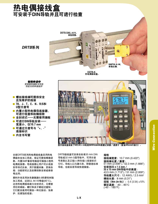
热电偶接线盒可安装于DIN 导轨并且可进行检查图示接线盒连接了RECK1-10电缆和HH506RA 数据记录器/温度计(配备RS232C 接口)。
DRTB 系列全新DRTB 系列热电偶接线盒采用热电偶级合金加工而成,保证可提供精确读数。
内置SMP 兼容母插座可插接小型热电偶连接器。
母连接器让用户可以连接到手持式仪表,用于数据采集、质保合规、功能研究以及故障排除安装或维修等应用。
塑料外壳采用灰色聚酰胺6.6热塑性树脂加工而成,达到UL 94 V0等级(85°C)。
这些热电偶接线端为全封闭式,无需使用任何端板。
螺钉和夹子都经过镀锌,它们配合使用可提供一种无振动、免维护、抗腐蚀的连接。
规格接线端宽度:10.7 mm (0.422")接线端长度/高度:51 mm (2.008")/42.3 mm (1.666")安装到35 x 7.5 mm /35 x 15 mm DIN 导轨中的高度: 43.5 mm (1.713")/51 mm (2.009")导线最大尺寸:12 AWG /2.5 mm 2裸线长度:8 mm (0.31")扭矩(Nm (in-lb)):0.4 (3.54) ±10%额定温度:-40 ~ 85°C (-40 ~ 185°F)DRTB-K , 热电偶接线盒。
DRTB-RAIL-3575,单独销售。
受美国和国际专利及待批专利申请保护专利申请中DRTB 接线盒可安装在标准35 mm DIN 导轨或32 mm G 型导轨中,可用分度号类型以及正极(+)和负极(-)连接标识它们。
导线入口为漏斗形,即便是标准导线,也能实现导线快速插接。
W i r e C o n n e c t i o nL-Xl 螺丝接线端可提供安全 且免维护的连接lT K 、J 、T 、E 、N 、R/S 和 U 型分度号l 内置小型热电偶母连接器,可进行检查和故障排除l 全封闭式——无需使用端板l可进行DIN 导轨安装—— 宽度小,仅10.7 mm l可通过分度号与“+,-” 连接标识l 内含书写窗SMPW-K-M, 单独出售.2配件订购示例:DDRTB-K ,K 型热电偶接线盒,可安装于DIN 导轨,配备RECK1-10,K 型0.3 m (1')可伸缩延长电缆。
美国欧米茄带状加热器
带状加热器简介什么是带状加热器?带状加热器是安装在表面并用于加热表面或空气(气体)的设备。
Omegalux® 带状加热器的应用OMEGALUX® 带状加热器主要用于对流式空气加热和夹紧式安装。
无论哪种应用,在选择带状加热器时都必须考虑两大因素:1.一个是合适的护套材料,用于抵御过程或环境中固有的锈蚀和氧化作用,并承受所需的温度。
标准的护套材料包括防锈铁、铬钢以及镍铬铁合金(仅限 NS 系列)。
不锈钢和蒙乃尔合金护套需要额外收费。
最大工作和护套温度如下所示。
2.一个是元件的功率密度,即加热区域每平方英寸的功率值。
加热沥青、糖浆及其它导热性较差、较为稠密的物质时,应选择较低的功率密度值;而加热空气、金属及其它导热材料时,此参数可以更高。
(请参见下面的曲线以确定允许的功率密度)。
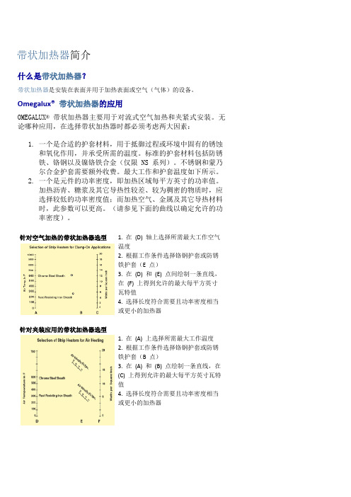
针对空气加热的带状加热器选型针对夹装应用的带状加热器选型1. 在(D) 轴上选择所需最大工作空气温度2. 根据工作条件选择铬钢护套或防锈铁护套(E 点)3. 在(D) 和(E) 点间绘制一条直线,在(F) 上得到允许的最大每平方英寸瓦特值4. 选择长度符合需要且功率密度相当或更小的加热器1. 在(A) 上选择所需最大工作温度2. 根据工作条件选择铬钢护套或防锈铁护套(B 点)3. 在(A) 和(B) 点绘制一条直线,在(C) 上得到允许的最大每平方英寸瓦特值4. 选择长度符合需要且功率密度相当或更小的加热器选择翅片带状加热器的功率密度1. 在 A 上选择所需最大工作温度2. 选择适合工作条件的护套材料 3. 在 B 上选择预期的最小空气流速。
注意:自然循环相当于每秒一英尺4. 在 A 和 B 上所选的点之间绘制一条直线,在 C 上得到允许的功率密度5. 选择长度符合需要且功率密度相当或更小的加热器所需工作温度较高时,必须限制功率密度,以防超出最大护套温度。
每个带状加热器的功率密度可在“订购指南”表中查阅。
通常,导热率低的粘性材料需要较低的功率密度。
Omega高温加热线说明书

81,7(' 67$7(6 ZZZRPHJDFRP 7&20(*$
6WDPIRUG &7
&$1$'$ ZZZRPHJDFD /DYDO 4XHEHF 7&*$
81,7(' .,1*'20 ZZZ RPHJDFRXN 0DQFKHVWHU (QJODQG
More than 100,000 Products Available!
7HPSHUDWXUH
Calibrators, Connectors, General Test and Measurement Instruments, Handheld Instruments for Temperature Measurement, Ice Point References, Indicating Labels, Crayons, Cements and Lacquers, Infrared Temperature Measurement Instruments, Recorders, Relative Humidity Measurement Instruments, PT100 Probes, PT100 Elements, Temperature & Process Meters, Timers and Counters, Temperature and Process Controllers and Power Switching Devices, Thermistor Elements, Probes and Assemblies, Thermocouples, Thermowells and Head and Well Assemblies, Transmitters, Thermocouple Wire, RTD Probes
Omega MWTC 无线智能热电极连接器系列说明书

Miniature WirelessThermocouple ConnectorsIndustrial UsesJU A vailable in 9 Thermocouple Calibrations U B uilt-In Cold Junction Compensation and Linearization U M WTC-REC Receivers Work with Multiple Wireless Remote Connectors U L ow Power Operation and Sleep Mode for Extended Battery Life U E ach Wireless Connector Transmits Measured and Ambient Temperatures in Real Time U F ree Software Converts Your PC Into a Multi-Channel Chart Recorder or Data LoggerConnector Series features stand-alone, compact,battery powered thermocouple connectors that transmit measurement data back to a mating receiver up to 90 m (300') away. When activated the connector will transmit readings continuously at pre-set time interval that was programmed by the user during the initial setup. Each unit measures and transmits: thermocouple input reading and connector ambient temperature to a receiver and is displayed on the PC screen in real time using the free provided software. When used with an MWTC-REC receiver, data from multiple wireless thermocouple connectors can be received and displayed. Each unit includes free software that converts your PC into a strip chart recorder or data logger so readings can be saved and later printed or exported to a spreadsheet file.Laptop not included.Universal input accepts standard and miniature connectors.Included software turns your PC into a meter, data logger and chart recorder.MWTC SeriesU p T o 48h a n n e l s !MWTC-REC1, USB receiver.MWTC-A-K shown actual size.W The MWTC can transmit thermocouplereadings wirelessly to your PC, up to300' away.U Choose From USB orAnalog Output ModelsU USB Models Accept48 Wireless InputsU Economical SingleChannel Model withAnalog OutputU Wirelessly Transmit upto 90 m (300')The MWTC-REC series is a familyof wireless receivers designed towork with the MWTC transmitters.Three models are available to meetyour application needs, with eitherUSB communication to a PC, oranalog output(s) to drive a remotedisplay, recorder, data logger orPLC. Transmissions of up to 90 m(300') are possible with the MWTC.The MWTC-REC1 is a compactmulti-channel receiver that connectsto your PC through a 1.8 m (6')cable (included). It is capable ofworking with up to 48 individual MWTC wireless connectors.The miniature MWTC-REC5 is designed for shorter distances, such as testing and laboratory applications. The size of a flash drive, the MWTC-REC5 plugs right into USB port. The MWTC-REC6 is a compact, single channel receiver that provides an analog output that corresponds to the input range of the MWTC wireless connector it is paired to.Transmitter Specifications Thermocouple Measurement Range: J: -100 to 760°C (-148 to 1400°F)K: -100 to 1260°C (-148 to 2300°F) T: -200 to 400°C (-328 to 752°F)E: -200 to 1000°C (-328 to 1832°F)R: 260 to 1760°C (500 to 3200°F)S: 260 to 1760°C (500 to 3200°F)B: 870 to 1820°C (1598 to 3308°F)C: 0 to 2315°C (32 to 4200°F): -100 to 1260°C (-148 to 2300°F) Measurement Accuracy (Greater of): J, K: ±0.5% of rdg or ±1.0°C (1.8°F) T, E, N: ±0.5% of rdg or ±2.0°C (3.6°F) R, S, B, C: ±0.5% of full scale Receiver SpecificationsPowerMWTC-REC1: USB bus +5Vpowered, 300 mA consumptionMWTC-REC5: USB bus +5Vpowered, 300 mA consumptionMWTC-REC6: 12 to 24 Vdc at 50 mAUSB Compatibility: USB 1.1, USB 2.0LED Indicators:USB power (green, MWTC-REC1 only)Radio Frequency (RF): 915/868 MHzUSB Cable Type: USB 4P(A) maleAnalog Output (MWTC-REC6): One,non-isolated 0 to 5 Vdc or 0 to 10 VdcAmbient Operating: -10 to 70°C(14 to 158°F), 0 to 95% RH(non-condensing)DimensionsMWTC-REC1: 70 L x 51 W x 20.5 mm H(2.75 x 2 x 0.8")MWTC-REC6: 76 x 32 x 26 mm H(3 x 1.25 x 1")Weight:MWTC-REC1: 89 g (0.2 lb) with cableMWTC-REC6: 102 g (3.6 oz)Enclosure/Housing:PlasticMeasurement Resolution:-10 to 70°C (14 to 158°F)Thermocouple Connection:(SMPW Series) mating connectorOperating Environment: -10 to 70°C(14 to 158°F)Computer Interface: USB (one interfacecable included withMWTC-REC1 receiver)Transmit Sample Rate: Programmablefrom 2 seconds to 2 minRadio Frequency: ISM 915 MHz or ISM868 MHzRF Output Power: 10 dBm (10 mW)Approvals:Model MWTC-(*)-915: FCC, Class BModel MWTC-(*)-868: CERange of RF Link:Up to 90 m (300'): Outdoor line of sightUp to 39 m (130'): Indoor/urbanSoftware: Requires Windows® OSBattery: AAA size; 1.5V lithium included;also compatible with 1.5V alkaline or3.6V lithiumBattery Life (Typical): 330 days at 1sample/minute reading rate@25°C (77°F)Data Transmitted to Receiver:Thermocouple reading andconnector ambient readingDimensions: 76 L x 25.4 W x 13 mm H(3 x 1 x 0.5")Enclosure: Plastic (Nylon)Note: Because of transmission frequencyregulations, these products may only be usedin the United States and Canada (915 MHzmodels) or Europe (868 MHz models).Wireless connectorssold separately, visit.MWT C-RE C5-915 sho wnsmall er tha n act ual si868o r915M H zMWTC-REC6shown smaller thanactual size.MWTC-REC6shown smaller thanactual size.Shown with mounting bracket installed (included).sensor. Units for other calibrations supplied with subminiature mating connector. MWTC-REC receivers include software. MWTC-PC programming cable is included with the MWTC-REC1 (not included with MWTC-REC5 or MWTC-REC6). * Specify calibration: J, K, T, E, R, S, B, C or N** Specify ISM frequency: “915” for USA/Canada or “868” for Europe † Specify analog output type: “V1” for 0 to 5 Vdc, or “V2” for 0 to 10 Vdc ‡ Specify calibration: J, K, T or EUSA, Canada Ordering Example: Two MWTC-A-K-915, 915 MHz wireless Type-K thermocouple connector/transmitters, MWTC-REC1-915 multi-channel 915 MHz receiver.Europe Ordering Example: Two MWTC-A-K-868, 868 MHz wireless Type-K thermocouple connector/transmitters, MWTC-REC1-868, multi-channel 868 MHz receiver.MWTC-REC5-915 868 o r915 M HzW a l lM o u n t ed1 C h a n n e lA n a l o g O u t p u tMWTC-A DISCONTINUED-。
Omega 产品说明书:磁性接触器、特殊用途接触器、高功率温度控制

EN-MC2 relay enclosure, $53, shown smaller than actual size.
SPECIFICATIONS
Mounting Holes: Keyhole slots and regular holes are embossed to facilitate mounting on uneven wall surfaces Knockouts: NEMA 1 (IP10) enclosures have ample knockouts for wiring General: Enclosures are drawn steel with a baked gray acrylic lifetime finish
MAGNETIC CONTACTORS
SPECIAL PURPOSE CONTACTORS FOR
HIGH-POWER TEMPERATURE CONTROL
MC3-3-75-240, $237.
Shown slightly smaller than actual size.
MC2-3-50-240, $109.
MC2-3-40-120
99 120 Vac coil, 40 Amp, 3-pole magnetic contactor
MC2-3-40-240
99 240 Vac coil, 40 Amp, 3-pole magnetic contactor
MC2-3-50-240
109 240 Vac coil, 50 Amp, 3-pole magnetic contactor
SHOP
ONLINE AT
sm To download information and
美国欧米茄omega热敏电阻元件

D-9珠状热敏电2.4 PFA 护套76.2 (3) 长32号 镀锡铜线珠状热敏电阻直径为2.8 (0.11)。
50.0 (2) 最小值76.2 (3)珠状热敏电阻, 图片为实际尺寸。
珠状热敏电阻,图片为实际尺寸。
32号镀锡铜线U 最高工作温度75°C (165°F)或150°C (300°F)(参见下表) U 可互换性误差为±0.1或±0.2°C (参见下表)电阻和温度特征Steinhart-Hart 方程是一种普遍认可的用于指定热敏电阻的电阻和温度特征的方法。
下面是温度作为电阻的函数的Steinhart-Hart 方程:1⁄T = A + B [Ln(R)] + C [Ln(R)]3其中:A 、B 和C 是从3个温度测试点得到的常数。
R = 热敏电阻的电阻值,单位Ω T = 温度,单位开氏度alpha = ((A-(1/T))/C)beta = SQRT(((B/(3C))3)+(alpha 2/4)) T = 开氏温度 (°C + 273.15)可在表1中找到每个所选热敏电阻的常数A 、B 和C 。
利用这些常数和上面的方程,可根据热敏电阻的电阻值得出其温度,或者得出热敏电阻在某一特定温度时的电阻值。
典型的温度漂移(互换性为±0.2°C 的元件)76.2 (3)D-10D容差曲线热敏电阻传感器的精度容差用温度的百分数表示。
它也称为互换性。
我们列出了我们的热敏电阻的两个基本精度/互换性规格:0 ~ 70°C (32 ~ 158°F)范围内 为±0.10°C 和±0.20°C 。
可在Z-236和Z-237页上找到我们的热敏电阻产品的温度和电阻表。
精度规格±0.1%或0.2%表示,在0 ~ 70°C (32 ~ 158°F)范围内每个热敏电阻的电阻值都在该限值范围内。
omega连接器OTP系列
omega连接器OTP系列
产品特点
∙3插脚/针标准设计
∙热电偶颜色编码的ANSI
∙白色无补偿适用
∙耐220°C (425°F)高温的玻璃填充尼龙
产品描述
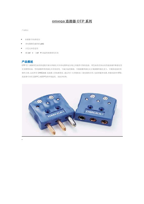
OTP型三插脚带色标的快速脱开插头和插孔可在热电偶和延长线之间提供可靠的连接。
带色标的壳体由高性能玻璃纤维强化型尼龙模塑而成。
管状插脚和筒状插孔具有低密度,可减少温度梯级。
负极插脚和插孔比正极插脚和插孔更大,可确保连接时的极性正确。
这是所有OMEGA® 连接器上的标配特征。
建议用于大多数要求三线电路的应用,包括屏蔽热电偶、热敏电阻和RTD。
连接器可承受220°C (425°F)的环境温度。
高抗冲结构。
Omega HH800系列产品说明书
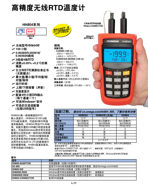
L-17配件HH804系列HH804U 是一款高精度的RTD 输入温度计。
HH804U 与100 Ω铂RTDs 配合使用,可选择3种不同温度系数曲线。
HH804U 符合ITS-90标准,标配内置的USB 端口和直流电源插孔。
可选的Windows 软件和交流适配器可以在较长的一段时间内将数据实时记录到PC 。
HH804W 提供快速并且简单易用的无线接口代替USB 。
这样可在长达25 m (75')的距离进行实时数据传输。
HH804是基本版本,不带无线或USB 接口。
U无线型号HH804W U 100 Ω铂U 0.00385/0.003916/ 0.003926曲线U 3线或4线RTD U 读数±0.05% +0.2°C 的高精度U 包含NIST 可溯源校准证书 (无数据点)U 最大值/最小值/平均值/相对值/保持U 运行时间U 上限/下限报警(声音)U 双温度显示U 配备4针小型DIN 插头 (每个通道一个)U 可选Windows ® 软件U 可选的交流适配器 (仅限USB 型号)据点请添加后缀“E”,无额外费用。
配备HH804-CONNECTOR(每个通道1个)、橡胶护套、NIST 证书(无数据点)、 4节“AAA”电池和操作手册。
订购示例: HH804U, 高精度RTD 输入温度计及HH800-SW ,Windows 软件和USB 电缆, OCW-3 OMEGACARE SM 将标准1年保修期延长至4年。
提供无线型号!通过1个接收器监测多达10个不同仪表订购备用DIN 连接器, HH804-CONNECTORHH804U , 双RTD 输入。
高精度无线RTD 温度计规格测量范围:0.00385 (100 Ω): -200.0 ~ 800.0°C (-328.0 ~ 1472.0°F)0.003916/0.003926 (100 Ω):-200.0 ~ 630.0°C (-328.0 ~ 1166.0°F)精度: 23°C 下的标定精度 ±0.05%, <75% RH±(0.05%读数 + 0.2°C) ±(0.05%读数 + 0.4°F) 输入连接方式: DIN 上的4针小型插头 测量速度: 1次/秒工作环境: 相对湿度<70%时0 ~ 50°C。
PXM309_CH 美国OMEGA仪器简介

B-3
PXM319-020G[*]
PXM359-020G[*]
DP25B-E, DP41B
35 bar
PXM309-035G[*]
PXM319-035G[*]
PXM359-035G[*]
DP25B-E, DP41B
70 bar
PXM309-070G[*]
PXM319-070G[*]
PXM359-070G[*]
PXM359-001A[*]
DP25B-E, DP41B
2 bar
PXM309-002A[*]
PXM319-002A[*]
PXM359-002A[*]
DP25B-E, DP41B
3.5 bar
PXM309-3.5A[*]
PXM319-3.5A[*]
PXM359-3.5A[*]
DP25B-E, DP41B
DP25B-E, DP41B
140 bar
PXM309-140G[*]
PXM319-140G[*]
PXM359-140G[*]
DP25B-E, DP41B
200 bar
PXM309-200G[*]
PXM319-200G[*]
PXM359-200G[*]
DP25B-E, DP41B
350 bar
PXM309-350G[*]
B
7 bar
PXM309-007A[*]
PXM319-007A[*]
PXM359-007A[*]
DP25B-E, DP41B
15 bar
PXM309-015A[*]
PXM319-015A[*]
PXM359-015A[*]
DP25B-E, DP41B
Omega PT 系列电气连接器说明书

e-mail:**************User’s GuidePT SERIESElectrical ConnectorsTwist Lock TypeShop online atIntroductionThe OMEGA ®PT Series Connectors are miniature, quick-disconnect and environment-resisting, designed for operation between -55 and 125°C (-67 and 257°F). Solder contacts are provided. Designed to accommodate both power and signal circuitry, these connectors are available in a great variety of sizes and contact configurations. Solder type contact connectors are pressure-tight and immersion proof. Crimp contact connectors provide a pressure tight seal when mated. Refer to Table 1.Table 1Features• Rugged Aluminum Shells • Rated to 125°C (257°F)• Strain Relief Cable Clamp • Secure Solder Contacts • #20 AWG Wire Size• High Conductivity Gold Plated ContactsPin AssignmentsNo. of Part No.ContactsPT01F8-4P4PT01F10-6P 6PT06F8-4S 4PT06F10-6S62SpecificationsInsulation Resistance at 25°C:5000 megohms min.(77°F)Voltage Drop:#20 contact, #20 wire, at 7.5 A, 55 mV max.Air Pressure:30 psi at -55°C (-67°F)Water Immersion: 1.8 m (6'), 48 hoursDurability:500 cycles of coupling and uncoupling Shells:Aluminum alloy, 0.0003 cadmium plate with olive drab chromate Insulators:NeopreneContacts:High conductivity copper alloy, 0.000050 gold over copper Dimensions:See Figure 1MaleFemaleFigure 1. Dimensions for PT01F and PT06F3M0262/0902It is the policy of OMEGA Engineering, Inc. to comply with all worldwide safety and EMC/EMI regulations that apply. OMEGA is constantly pursuing certification of its products to the European New Approach Directives. OMEGA will add the CE mark to every appropriate device upon certification.The information contained in this document is believed to be correct, but OMEGA accepts no liability for any errors it contains, and reserves the right to alter specifications without notice.WARNING: These products are not designed for use in, and should not be used for, human applications.Direct all warranty and repair requests/inquiries to the OMEGA Customer Service Department. BEFORE RET URNING ANY PRODUCT (S) T O OMEGA, PURCHASER MUST OBT AIN AN AUT HORIZED RET URN (AR) NUMBER FROM OMEGA’S CUST OMER SERVICE DEPART MENT (IN ORDER T O AVOID PROCESSING DELAYS). T he assigned AR number should then be marked on the outside of the return package and on any correspondence.The purchaser is responsible for shipping charges, freight, insurance and proper packaging to prevent breakage in transit. FOR WARRANTY RETURNS, please have the following informa-tion available BEFORE contacting OMEGA:1.Purchase Order number under which the product was PURCHASED,2.Model and serial number of the product under warranty, and3.Repair instructions and/or specific problems relative to theproduct.FOR NON-WARRANTY REPAIRS,consult OMEGA for cur-rent repair charges. Have the following information avail-able BEFORE contacting OMEGA:1. Purchase Order number to cover the COST of the repair,2.Model and serial number of the product, and3.Repair instructions and/or specific problems relative to the product.OMEGA’s policy is to make running changes, not model changes, whenever an improvement is possible. This affords our customers the latest in technology and engineering.OMEGA is a registered trademark of OMEGA ENGINEERING, INC.© Copyright 2006 OMEGA ENGINEERING, INC. All rights reserved. T his document may not be copied, photocopied, reproduced, translated, or reduced to any electronic medium or machine-readable form, in whole or in part, without the prior written consent of OMEGA ENGINEERING, INC.Servicing North America:U.S.A.:One Omega Drive, Box 4047ISO 9001 Certified Stamford, CT 06907-0047Tel: (203) 359-1660FAX: (203) 359-7700e-mail:**************Canada:976 BergarLaval (Quebec) H7L 5A1, Canada Tel: (514) 856-6928FAX: (514) 856-6886e-mail:*************For immediate technical or application assistance:U.S.A. andSales Service: 1-800-826-6342/1-800-TC-OMEGA Canada:Customer Service: 1-800-622-2378/1-800-622-BEST Engineering Service: 1-800-872-9436/1-800-USA-WHEN Mexico:En Espan ˜ol: (001) 203-359-7803e-mail:*****************FAX: (001) 203-359-7807**************.mxServicing Europe:Czech Frystatska 184, 733 01 Karviná, Czech Republic Republic:TEL: +420 (0)59 6311899FAX: +420 (0)59 6311114Tol Free: 0800-1-66342e-mail:*****************Germany/Daimlerstrasse 26, D-75392 Deckenpfronn, Germany Austria:Tel: +49 (0)7056 9398-0FAX: +49 (0)7056 9398-29TollFreeinGermany************e-mail:*************United One Omega Drive, River Bend Technology Centre Kingdom:Northbank, Irlam, ManchesterISO 9002 Certified M44 5BD United KingdomTel: +44 (0)161 777 6611FAX: +44 (0)161 777 6622Toll Free in United Kingdom: 0800-488-488e-mail:**************.uk。
热电偶插头介绍
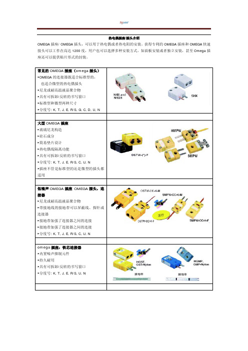
omega 插座:铁芯连接器 ►内置噪声抑制元件 ►持久耐用 ►具有可拆卸/反转的书写窗口 ►分度号: K, T, J, E, R/S, U, N
配件型号
SMP-SC SWHCL
应用组件
SMPW,HMPW SMPW,HMPW
JP ►便于安装,装饰性强 ►自我保护设计
SPJ ►接所有标准型的插头 ►接受接受 OTP 系列 3 重连接器
TPJ ►无需特殊硬件安装工具
RSJ ►接受所有标准型的插头 RMJ ►接受所有微型的插头 ►紧凑尺寸 MPJ ►接受所有微型的插头
耐高温型陶瓷连接器 ►高纯度,重型陶瓷坯体 ►耐温 650°C (1200°F) ►便于接线的大型终端螺钉 ►可移动彩色编码点 ►分度号: K, T, J, E, R/S, G, C, D, U, N
线路板连接器 ►新推出垂直型 ►玻璃纤维尼龙 220°C (425°F) ►被 OEM 所用 ►直接安装在电路板上 ►专为手持式温度计所用 ►J, K, T, E, N 和 U 型号
( 3 ) 线长
M 代表只有插头 F 代表只有插座 MF 代表插头/插座对
SMPW-K-M 热电偶插头: SMPW-K-M 表示为 SMPW 系列,K 型分度号,M 代表为插头,适用于 K 型 OMEGA 热电偶测温线或者其他品牌热电偶 测温线之间的连接。
OMEGA 插座 OMEGA 插头特性:
按照 ANSI 和 IEC 标准上色 专有外覆螺旋 可接受最大 20AWG 的绞线或实心线 SMP & SMPW 系列耐温摄氏 220 度(华氏 425 度) HMP & HMPW 系列耐温摄氏 260 度 (华氏 500 度) HMP & HMPW 系列拥有对环境无害的无镉外壳
OmegaLux高 中功率密集体热电缸加热器说明书
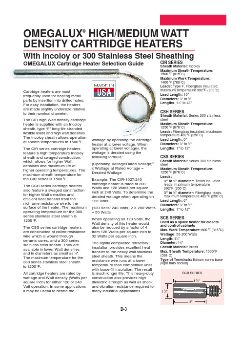
D-3OMEGALUX ®HIGH/MEDIUM WATT DENSITY CARTRIDGE HEATERSWith Incoloy or 300 Stainless Steel SheathingOMEGALUX Cartridge Heater Selection GuideCIR SERIESSheath Material:IncoloyMaximum Sheath Temperature:1500°F (815˚C)Maximum Work Temperature: 1400°F (760˚C)Leads:Type F, Fiberglass insulated,maximum temperature 392°F (200˚C)Lead Length:10"Diameters:1⁄4" to 3⁄4"Lengths : 11⁄4" to 48"CSH SERIESSheath Material:Series 300 stainless steelMaximum Sheath Temperature:1250°F (676˚C)Leads:Fiberglass insulated, maximum temperature 482°F (250˚C)Lead Length:6"Diameters:1⁄4" to 3⁄4"Lengths:1" to 12"CSS SERIESSheath Material:Series 300 stainless steelMaximum Sheath Temperature:1250°F (676˚C)Leads:1⁄8" to 1⁄4" diameter: Teflon insulated leads, maximum temperature 392°F (200˚C)3⁄8" to 3⁄4" diameter:Fiberglass leads,maximum temperature 482°F (250˚C)Lead Length:6"Diameters:1⁄8" to 3⁄4"Lengths:1" to 12"SCB SERIESUsed as a space heater for closets and control cabinetsMax. Work Temperature:600°F (315°C)Wattage:50-200 Watts Length:43⁄4"DIameter:13⁄8"Sheath Material: BrassMax. Sheath Temperature: 1000°F (538˚C)Type of Terminals: Edison screw base (light bulb socket)Cartridge heaters are mostfrequently used for heating metal parts by insertion into drilled holes.For easy installation, the heaters are made slightly undersize relative to their nominal diameter.The CIR high Watt density cartridge heater is supplied with an Incoloy sheath, type “F” long life stranded flexible leads and high watt densities.The Incoloy sheath allows operation at sheath temperatures to 1500°F.The CIR series cartridge heaters feature a high temperature Incoloy sheath and swaged construction,which allows for higher Watt densities and maximum life athigher operating temperatures. The maximum sheath temperature for the CIR series is 1500°F.The CSH series cartridge heaters also feature a swaged construction for higher Watt densities and efficient heat transfer from the nichrome resistance wire to thesurface of the heater. The maximum operating temperature for the 300series stainless steel sheath is 1250°F.The CSS series cartridge heaters are constructed of coiled resistance wire which is wound through ceramic cores, and a 300 series stainless steel sheath. They are available in lower Watt densities and in diameters as small as 1⁄8".The maximum temperature for the 300 series stainless steel sheath is 1250°F.All cartridge heaters are rated by wattage and Watt density (Watts per square inch) for either 120 or 240Volt operation. In some applications it may be useful to derate thewattage by operating the cartridge heater at a lower voltage. When operating at lower voltages, the wattage is derated using the following formula:(Operating Voltage/Rated Voltage)2x Wattage at Rated Voltage =Derated WattageExample: The CIR-1027/240cartridge heater is rated at 200Watts and 128 Watts per square inch at 240 Volts. To determine the derated wattage when operating on 120 Volts:(120 Volts/ 240 Volts) 2 X 200 Watts = 50 WattsWhen operating on 120 Volts, the Watt density of this heater would also be reduced by a factor of 4from 128 Watts per square inch to 32 Watts per square inch.The tightly compacted refractory insulation provides excellent heat transfer to the heavy wall stainless steel sheath. This means the resistance wire runs at a lower temperature than competitive units with loose-fill insulation. The result is much longer life. This heavy-duty construction also provides high dielectric strength as well as shock and vibration resistance required for many industrial applications.APPLICATION OF OMEGALUX®CARTRIDGE HEATERS — CIR SERIESOMEGALUX cartridge heaters are most frequently used for heating metal parts by insertion into drilled holes. For easy installation, the heaters are made slightly undersize relative to their nominal diameter. Application at medium Watt densities. Figure D-1 (page D-6) shows maximum allowable Watt density for various fits and operating temperatures . The vast majority of applications do not require maximum watt/in2, however. Use a Watt density only as high as you need. Take advantage of the safety margin provided by using ratings less than the maximum allowed. Select space heaters for most even heat pattern rather than for the highest possible wattage per heater. At medium Watt densities, general purpose drills are usually adequate for drilling holes. Typically, these result in holes .003" to .008" over the nominal size of the drill, resulting in fits of .010" .015". Of course, the tightest fit is desirable from a heat transfer standpoint, but somewhat looser fits aid in installing and removing cartridge heaters, especially long ones. Holes drilled completely through the part are recommended to facilitate removal of the heater. After drilling, clean or degrease the part to remove cutting lubricants.Application at high Watt density. OMEGALUX cartridge heaters are designed and manufactured to provide Watt density capabilities second to none. To obtain best life at the highest Watt densities allowed by Fig. D-1 (page D-6), close attention to application details is suggested.a.For closest fit and best heat transfer, holes should be drilled and reamed, rather than just drilled to final diameter with a general purpose drill.Determining fit. At high watt densities, a close fit is important. The fit is the difference between the minimum diameter of the heater and maximum diameter of the hole. Forexample, at 1⁄2"diameter anOMEGALUX cartridge heater isactually .498" plus 000" minus.005". If this heater is placed in ahole which has been drilled andreamed to a diameter of .503" -.493" = .010").b.The sensor for the temperaturecontrol should be placed betweenthe working surface of the part andthe heaters. The temperature of thepart approximately 1⁄2" away from theheaters is used in selectingmaximum allowable Watt densityfrom the graph.c.Control of power is an importantconsideration in high Watt densityapplications. On-off control isfrequently utilized, but it can causewide excursions in the temperatureof the heater and working parts.Thyristor power controls arevaluable in extending the life of highWatt density heaters, since theyeffectively eliminate on-off cycling.Determining Watt density. Theterm "Watt density" refers to theheat flow rate of surface loading. Itis the number of Watts per squareinch of heated surface area. Forcalculation purposes, stockcartridge heaters have 1⁄4" unheatedlength at each end. Thus, for a 1⁄2" x12" heater rated 1000 Watts, theWatt density calculation would be asfollows:Watt density =Wπn x D x HLW = wattage = 1000WD = diameter = .5 in.HL= heater = 11.5 in.Watt density = 10003.14 x 5 x 11.5= 55 W/in.Selecting sizes and ratings. Thecalculation of total heatrequirements for an application isoutlined in the technical section Z.For assistance, contactOMEGALUX.Once total heat requirements areestablished, the quantity, size andrating of cartridge heaters can bedecided. Plan for enough heaters topermit even temperatures throughthe part during heat-up andoperation. The sensor for thetemperature control should beplaced close to working surface foraccurate control.After the wattage for each heaterhas been established, the Wattdensity and fit must be calculated.Then, use Fig. D-1 on page D-6 tobe sure that the Watt density iswithin allowable limits. For example,a1⁄2" x 12" OMEGALUX CIR seriesrated 1000 Watts has a Watt densityof 55/in2. If it were used in a partwith an operating temperature of1000°F with a fit of 0.10", theallowable Watt density from thegraph would be 90W/in2,thus, theactual Watt density of 55w/in2iswell below the maximum allowed. Asubstantial safety margin wouldexist and high reliability can beexpected.If the heater selected had a Wattdensity higher than that allowableby graph, then those changes couldbe considered.ing more heaters of lower wattdensity.ing longer or larger diameterheaters.3.Improving the fit.4.Reducing heat requirements byreducing heat losses or byallowing for longer heat-up time.D-4HEATING PLATENS, DIES, MOLDS USING CARTRIDGE HEATERS–CIR SeriesThis heating application may usually be easily accomplished by using cartridge heaters, although in some applications strip or tubular heaters can be inserted in grooved slots in the metal. When cartridge heaters are used, it is essential that the following factors are checked to insure that the heater will experience the longest possible life and provide sufficient heat for the job:1. Sheath watt density.2. Proper fit of cartridge heater inmachined hole.3. Provisions made to protect heaterfrom contamination from oil, oilvapors, etc.4. Sufficient kW is installed toaccomplish work and make up for heat losses from the flat surface. The maximum permissible sheath watt densities for alloy sheath cartridge heaters at a given desired temperature on the metal are given by Figure D-1. This curve gives watt densities for various fits using CIR cartridge elements. Figure D-2 is useful for using C series elements. When cartridge heaters are installed in a drilled hole, the hole should be drilled to the nominal diameter of the heater. Cartridge heater diameters are actually .003" to .005" smaller than the nominal diameter. This allows for easy installation when cold, but upon heating the cartridge heater expands for a snug fit and excellent heat transfer. When cartridge heaters are used in plastic forming dies, extruders, etc., care must be taken to protect the heater from possible contaminationentering through the terminal end.Standard end opposite terminalconstruction for standard cartridgeheaters is a positive weld.Special moisture and abrasiveresistant terminal construction isavailable and where moisture orcontamination problems are present,hermetic seals can be supplied (seepages D-15 and D-16).CARTRIDGE HEATERSA plastic forming operation requires2 lb. of plastic to be processed perhour; the plastic has a specific heatof 0.45 BTU/lb/°F and reaches apliable state at 300°F. Two platens,each weighing 245 Ibs. andmeasuring 24 in. long x 12 in. widex 3 in. thick, must be preheated to300°F in 1⁄2hour. The platens are notinsulated. The steel platens have aspecific heat of 0.12 BTU/lb°F.Heat-up is accomplished with theplatens closed. In addition, lossesencountered during operation (fromopening and closing the platens) arenegligible. Room ambient is 70°F.The total exposed surface area isconsidered to be 7ft2.kW = WT xCp xΔT3412x HwhereWT= weight of material to be heatedCp= specific heat (BTU/Ib/°F)ΔT = temperature (°F)H = heat-up time in hours3412 is conversion factor of BTU tokWhk W REQUIREMENTS FORINITIAL HEAT-UPkW = 245 x2x0.12x(300-70)3412x1⁄2(hr)= 13524= 7.931706Losses during heat-up are 150 w/ft2(see Figure A-2 on page A-19, line”B” for oxidized steel) at theoperating temperature of 300°F.kW = 7.0(ft2)x150 (W/ft2)1000(W/kW)Average loss = 1.05= .53kW(Note 1)2Total reqd. = 7.93 + .53 = 8.468.46x1.2(safety factor) = 10.15kWOPERATINGREQUIREMENTSkW = 2(lbs) x0.45x(300-70)°F3412x1(hr)= 207= 0.0613412kW = 7.0(ft2)x150 (W/ft2)1000(W/kW)= 1.05Total reqd. = 0.061 + 1.05=1.111kW1.11 x 1.2 = 1.33 kWNOTE 1:Average heat loss is the heat loss at the final operating temperature divided by an averaging factor2. The averaging factor is used since during initial heat-up, the platen is not at the final operating temperature all of the time.D-5D-6DSince the heat-up requirement is greater than that for operation, we should install 10 kW.INSTALLATION AND SELECTION OF CARTRIDGE HEATERSHeater selection is often governed by available space.In this instance, however, space is not a problem since we can easily install 5 cartridge heaters CIR 3122 1⁄2in.diameter x 12 in. sheath length in each platen. Each unit can be rated 1000 Watts for a total installedcapacity of 10 kW. Holes for cartridge heaters should be drilled and reamed to 0.500 in. max., since close fits are important for best heat transfer. Holes in the platens should be drilled completely through the 12" wide platen to facilitate removal of heaters when necessary.Using the maximum allowable Watt density graphs:FIGURE D-1This graph is useful for choosing OMEGALUX ®Type CIR cartridge heaters. The curves should be considered as guides and not precise limits.The graph is based on a 1600°F resistance wire temperature inside the cartridge heater, when theheater is installed in an oxidized mild steel block.Watt density values from the graph should be lowered by about 10% or more when block materials are used which have a lower thermal conductivity or lower emissivity than oxidized mild steel.Maximum Watt Density vs.Platen Temperature for Various Fits Using Type CIR Cartridge HeatersFIGURE D-1Allowable Watt density vs platen temperature for various fits usingOMEGALUX ®Type CIR cartridge elements.HOW TO GET THE BEST PERFORMANCE FROM OMEGALUX CARTRIDGE HEATERS1. Installation recommendations.a.On moving machinery, anchor theleads securely. As little movementas possible should be allowed closeto where the leads emerge from theheater. A loop in the lead wire willfrequently extend lead life. Ifapplication conditions result incontinual lead flexing, terminate thecartridge heater leads at a terminalblock which moves from the heatedassembly. Flexing is transferred tothe extension leads which can beeconomically replaced.b.For rapidly vibrating equipment, employ the terminal block described above. Keep leads from heater to block short and well supported to prevent lead movement due to vibration.c.Protect leads from spray, oil, and abrasive. Contaminating liquids and vapors can enter unsealed cartridge heaters and cause insulation breakdown.d.Avoid tape on leads where they emerge from the cartridge heater. The adhesive on some tapes can enter the heater and turn to carbon which is electrically conductive. Where glass tape cannot be avoided, a tape with a silicone based adhesive is suggested.e.Design the installation so that the leads are in an ambient temperature which doesn’t exceed the rating on the lead insulation (392°F for standard leads).Where temperatures require it, use nickel or nickel plated copper wire with Teflon, silicone impregnated fiberglass or rockbestos insulation to extend leaders. (See Section H.)f.Graphite and other lubricants to help insert the cartridge heater into the hole are generally not recommended. These are electrically conductive and can get on the lead end of the heater unless extra care is taken.g.As operating temperatures go up, thermal insulation on the heated part becomes more desirable to conserve heat. Thermal insulation results in lower wattage requirements and therefore lowerWatt density on the heaters. Otherbenefits are more even worktemperatures and greater operatorsafety and comfort.h.Leads must not extend into thehole containing the cartridge heater.Generally, the lead end of theheater should be flush with surface.2. Vacuum Operation. Whenheaters are operated in a blockwhich is in a vacuum, the inside ofthe holes should be preoxidized toimprove emissivity. Substantialreductions in maximum allowableWatt density are usually necessaryfor vacuum operation. Wherepossible, the installation should bedesigned so that the lead end of theheater is outside the vacuum. Whenthe lead end of the heater is insidethe vacuum, a voltage of 120 Voltsor less is recommended. On anunsealed heater, outgassing may beexpected.3. Operation in square grooves.Round series CIR cartridge heatersmay be installed in square or V-shaped grooves if this provesconvenient. The inside of the grooveshould be treated to improve itsemissivity (by oxidizing oranodizing). Allowable W/in2can beestimated by using the .050 fit linein Figure D-1 on page D-6,providing that the square isapproximately the same width asthe nominal diameter of the heater.4. Operation on 480 Volts. (CIRSeries only) OMEGALUX CIRSeries cartridge heaters 5⁄8" diameterand larger can be operated on 480Volts. One approach is to take twostock 240-Volt heaters and connectthem in series on 480-Volts.Another is to order specially rated480-Volt cartridge heaters. ContactOMEGALUX.Because of higher voltage stressesinside the heater, lower maximumWatt densities are allowable in 480-Volt applications, either with two240-Volt heaters in series or withspecially rated 480-Volt units. Todetermine maximum allowable Wattdensity at 480-Volts, enter the graphon page D-6 with an operatingtemperature value which is 200°Fhigher than the actual operatingtemperature. A maximum operatingtemperature of 1000°F issuggested.An extra layer of high temperaturefiberglass sleeving is recommendedfor the leads to increase electricalinsulation.5. Testing recommendations.Testing under simulated operatingconditions is suggested whenequipment manufacturers designnew products. Cartridge heaters ofthe appropriate physical size areoperated on a variable transformeruntil the heat output is at the properlevel. Then, voltage and currentmeasurements are taken andrequired wattage rating iscalculated. Heaters of the correctwattage rating are then ordered forproduct design.D-7ߜType F Flexible Leadsߜ1⁄4",3⁄8"(1cm),1⁄2",5⁄8"&3⁄4"Inches in Diameterߜ120 & 240 VߜUL ComponentRecognized & C.S.A.CertifiedߜPatented DesignFEATURESType F leads, standard on CIR series, consist of standard, flexible manganese nickel wire insulated with impregnated fiberglass to approximately 392°F. the leads can be bent at a sharp angle where they emerge through the flush terminal block, without exposing bare conductors.When leads longer than 10" (25 cm) are needed, additional lengths of high-temperature wire can be spliced on stock heaters, either at the factory or by the user. Specially fabricated CIR series heaters can be supplied with unspliced leads up to 32" (81 cm) in length.Sheath material. OMEGALUX®CIR series cartridge heaters are made with a high-temperature Incoloy sheath material.Higher temperatures, fasterproduction rates. The CIR seriespatented construction and high-Watt-density capability let you putmore heat in less space.Welded end disc seals endopposite leads from contamination.Black oxide sheath.Blacktransfers heat better than shinysurfaces. OMEGALUX heaters go towork immediately when energizedand operate at cooler sheathtemperatures. Shiny heaters beginoperating at higher temperatures,shortening life expectancy whilethey slowly oxidized and turn black.Shock and vibration resistant.Tightly compacted refractoryinsulation for severe application.Lead length.CIR series heatersare stocked with Type F leads 10"(24 cm) long, ±3⁄8"(1cm). Longer leadlengths can be readily spliced on.Eliminating operational problems,the manganese nickel electricalleads are stranded, not solid. Theyremain continuously covered withfiberglass insulation even when bentsharply where they emerge from theheater. The construction is coveredby issued and pending patents.Cartridge heater performancedepends upon adherence to basicheat transfer principles. In theresistance winding inside thecartridge, electrical energy isconverted to heat energy with100%efficiency. CIR units are designedand constructed to maximize heatenergy flow and thus keepresistance wire temperaturerelatively low.Even temperature throughout theheater’s length is produced by theuniform winding of the wire on thesmooth supporting core. Close andeven spacing between wire andinside of sheath is maintained forgood heat transfer. Tight spacingbetween turns permits use oflargest gauge resistance wire.CIR SERIES HIGH WATT DENSITY CARTRIDGE HEATERS - WITH INCOLOY SHEATHINGExcellent oxidation and corrosion resistance is provided by special OMEGALUX alloy sheath. Thermal expansion characteristics of sheath and refractory are closely matched.Highest quality nickel-chromiumresistance wire is used for theresistance winding. Long life andconsistent performance from one unitto the next are assured.Heavy-gauge end disc, securelywelded, seals out contaminants. Thisrugged construction and oxidationresistance of sheath facilitate heaterremoval.Terminal block is flush with end of sheath, adding strength and protection from breakage..Refractory Insulation betweenresistance wire and sheath isspecially formulated and rigidlycontrolled to maintain high-temperature characteristics. Throughspecial processes it is denselycompacted to improve its thermalconductivity and dielectric strength.Patented connector eliminates anychance of overheating wherestranded lead is attached toresistance wire. Highly reliable, theconnector eliminates life-shorteningstress on the wire.USAD-8。
Omega Engineering OMEGATHERM 201 高热导率硅胶说明书

OT-201OMEGATHERM®Thermally Conductive Silicone PasteIntroductionOMEGATHERM®201 is a thermally conductive, “Heat Sink”silicone grease. It has a very high thermal conductivity coupled with high insulation resistance and high dielectric strength. The term heat sink compound or thermal joint compound is used to describe this type of material. It does not harden on long exposure to elevated temperatures, but retains its past-like consistency. It is rated for continuous use between -40°F and +392°F (40°C and 200°C). OMEGATHERM®is available in four quantity sizes, from a 1⁄2oz. jar to a 2 lb. can, as outlined below.OMEGATHERM 201 provides an excellent means of conducting heat and expanding the heat-path area from a surface to a temperature measurement sensor, thus increasing the speed of response and improving accuracy. OMEGATHERM 201 improves the heat transfer between a solid state relay and its finned heat dissipating heat sink. Apply a thin layer of “201” thermal compound to the bottom of the solid state relay (SSR), then securely mount the SSR on the finned heat sink with the supplied screws.Instructions for UseAlthough OMEGATHERM 201 does not normally settle in its container, storage for long periods of time at elevated temperature may result in a slight separation of the conductive fillers from the silicone oil. If this condition is seen to exist, the fillers may be easily mixed by hand or mechanical mixing.OMEGATHERM 201 may be dispensed through a nozzle using any appropriate hand operated or automatic equipment. For some applications, it will be convenient to apply thin films with a stiff brush.To CLEAN OT-201 from surfaces, use a solvent containing Alcohol, MEK, or Xylene. Repeated use is required to completely clean silicon grease from surface.ApplicationsA. Surface Measurement Probes-dab a small amount on thesurface and push the thermocouple into this area.B. Temporary Temperature Monitoring of Surfaces and Bodies-For applications to 392°F (200°C). OT-201 workswell with insulated wire thermocouples. Simply dab this paste on the surface or into a cavity, put the sensor in the paste, and tape to hold.C. Thermocouple Wells (to 200°C)-improve the response timeof your thermowell assemblies. Simply put enoughOMEGATHERM 201 into the bottom of the wells to cover the active length of the sensor. This application holds for vertical wells or those canted down.D. NOT FOR USE IN A VACUUM. OT-201 will outgas if usedin a vacuum.HygieneMAY CAUSE IRRITATION.1. Avoid contact with skin and eyes.2. Wash thoroughly after handling.First Aid1.In case of contact, wash skin thoroughly with soap and water.2. For eyes, flush with water for 15 minutes and consult physician immediately.FOR INDUSTRIAL USE ONLY.Typical PropertiesColor:Off-whiteTemperature Range of Use:-40°to +392°F(40°to +200°C) Consistency:Thick, smooth pasteVolume Resistivity:1014ohm-cmDielectric Strength:500 volts/mil (19.7 kv/mm) Thermal Conductivity:16 (BTU) (in)/(hr) (ft2) (°F)0.0055 (cal)/(cm)/(sec)(cm2) (°C)Specific Gravity: 2.53 g/ccWeight Loss:0.2% (24 hours/100°CShelf life: 1 Year (Storage at 35°F orbelow will approximatelydouble the shelf life). Solvents:Alcohol or MEK or XyleneSolventsThis information is not a warranty and assumes no legal responsibility. Actual suitability for a particular purpose is to be determined by the user.M0066/1104It is the policy of OMEGA Engineering, Inc. to comply with all worldwide safety and EMC/EMI regulations that apply. OMEGA is constantly pursuing certification of its products to the European New Approach Directives. OMEGA will add the CE mark to every appropriate device upon certification.The information contained in this document is believed to be correct, but OMEGA accepts no liability for any errors it contains, and reserves the right to alter specifications without notice.WARNING: These products are not designed for use in, and should not be used for, human applications.WARRANTY/DISCLAIMEROMEGA ENGINEERING, INC. warrants this unit to be free of defects in materials and workmanship for a period of 13 months from date of purchase.OMEGA’s WARRANT Y adds an additional one (1) month grace period to the normal one (1) year product warranty to cover handling and shipping time. This ensures that OMEGA’s customers receive maximum coverage on each product.If the unit malfunctions, it must be returned to the factory for evaluation. OMEGA’s Customer Service Department will issue an Authorized Return (AR)number immediately upon phone or written request. Upon examination by OMEGA, if the unit is found to be defective, it will be repaired or replaced at no charge. OMEGA’s WARRANTY does not apply to defects resulting from any action of the purchaser, including but not limited to mishandling,improper interfacing, operation outside of design limits, improper repair, or unauthorized modification. This WARRANTY is VOID if the unit shows evidence of having been tampered with or shows evidence of having been damaged as a result of excessive corrosion; or current, heat, moisture orvibration; improper specification; misapplication; misuse or other operating conditions outside of OMEGA’s control. Components in which wear is not warranted, include but are not limited to contact points, fuses, and triacs.OMEGA is pleased to offer suggestions on the use of its various products. However, OMEGA neither assumes responsibility for any omissions or errors nor assumes liability for any damages that result from the use of its products in accordance with information provided by OMEGA, either verbal or written. OMEGA warrants only that the parts manufactured by the company will be as specified and free of defects. OMEGA MAKES NO OTHER WARRANTIES OR REPRESENTATIONS OF ANY KIND WHATSOEVER, EXPRESSED OR IMPLIED, EXCEPT THAT OF TITLE, AND ALL IMPLIED WARRANTIES INCLUDING ANY WARRANTY OF MERCHANTABILITY AND FITNESS FOR A PARTICULAR PURPOSE ARE HEREBY DISCLAIMED. LIMITATION OF LIABILITY : The remedies of purchaser set forth herein are exclusive, and the total liability of OMEGA with respect to this order, whether based on contract, warranty, negligence, indemnification, strict liability or otherwise,shall not exceed the purchase price of the component upon which liability is based. In no event shall OMEGA be liable for consequential,incidental or special damages.CONDITIONS: Equipment sold by OMEGA is not intended to be used, nor shall it be used: (1) as a “Basic Component” under 10 CFR 21 (NRC), used in or with any nuclear installation or activity; or (2) in medical applications or used on humans. Should any Product(s) be used in or with any nuclear installation or activity, medical application, used on humans, or misused in any way, OMEGA assumes no responsibility as set forth in our basic WARRANT Y/DISCLAIMER language, and, additionally, purchaser will indemnify OMEGA and hold OMEGA harmless from any liability or damage whatsoever arising out of the use of the Product(s) in such a manner.Servicing North America:U.S.A.:One Omega Drive, Box 4047ISO 9001 CertifiedStamford, CT 06907-0047Tel: (203) 359-1660FAX: (203) 359-7700e-mail:**************Canada:976 BergarLaval (Quebec) H7L 5A1, Canada Tel: (514) 856-6928FAX: (514) 856-6886e-mail:*************For immediate technical or application assistance:U.S.A. and Canada:Sales Service: 1-800-826-6342 / 1-800-TC-OMEGA ®Customer Service: 1-800-622-2378 / 1-800-622-BEST ®Engineering Service: 1-800-872-9436 / 1-800-USA-WHEN ®TELEX: 996404 EASYLINK: 62968934 CABLE: OMEGAMexico:En Espan ˜ol: (001) 203-359-7803e-mail:*****************FAX: (001) 203-359-7807**************.mxOMEGAnet ®Online Service Internet e-mail***********************Servicing Europe:Benelux:Postbus 8034, 1180 LA Amstelveen, The Netherlands Tel: +31 (0)20 3472121FAX: +31 (0)20 6434643Toll Free in Benelux: 0800 0993344e-mail:*****************Czech Republic:Frystatska 184, 733 01 Karviná, Czech Republic Tel: +420 (0)59 6311899FAX: +420 (0)59 6311114Toll Free: 0800-1-66342e-mail:*****************France:11, rue Jacques Cartier, 78280 Guyancourt, France Tel: +33 (0)1 61 37 2900FAX: +33 (0)1 30 57 5427Toll Free in France: 0800 466 342e-mail:**************Germany/Austria:Daimlerstrasse 26, D-75392 Deckenpfronn, GermanyTel: +49 (0)7056 9398-0FAX: +49 (0)7056 9398-29TollFreeinGermany************e-mail:*************United Kingdom:One Omega Drive, River Bend Technology CentreISO 9002 CertifiedNorthbank, Irlam, Manchester M44 5BD United Kingdom Tel: +44 (0)161 777 6611FAX: +44 (0)161 777 6622Toll Free in United Kingdom: 0800-488-488e-mail:**************.ukRETURN REQUESTS /INQUIRIESDirect all warranty and repair requests/inquiries to the OMEGA Customer Service Department. BEFORE RETURNING ANY PRODUCT (S) T OOMEGA, PURCHASER MUST OBTAIN AN AUTHORIZED RETURN (AR) NUMBER FROM OMEGA’S CUSTOMER SERVICE DEPARTMENT (IN ORDER T O AVOID PROCESSING DELAYS). T he assigned AR number should then be marked on the outside of the return package and on any correspondence.The purchaser is responsible for shipping charges, freight, insurance and proper packaging to prevent breakage in transit.FOR WARRANTY RETURNS, please have the following information available BEFORE contacting OMEGA:1.Purchase Order number under which the product was PURCHASED,2.Model and serial number of the product under warranty, and3.Repair instructions and/or specific problems relative to the product.FOR NON-WARRANTY REPAIRS,consult OMEGA for current repair charges.Have the following information available BEFORE contacting OMEGA:1. Purchase Order number to cover the COST of the repair,2.Model and serial number of the product, and3.Repair instructions and/or specific problems relative to the product.OMEGA’s policy is to make running changes, not model changes, whenever an improvement is possible. T his affords our customers the latest in technology and engineering.OMEGA is a registered trademark of OMEGA ENGINEERING, INC.© Copyright 2004 OMEGA ENGINEERING, INC. All rights reserved. This document may not be copied, photocopied, reproduced, translated, or reduced to any electronic medium or machine-readable form, in whole or in part, without the prior written consent of OMEGA ENGINEERING, INC.。
OMEGATHERM 201 高热导填充硅胶粘合剂说明书

B-40OMEGATHERM ® 201OMEGATHERM ® 201—is a very high thermallyconductive filled silicone paste, ideally suited for many temperature measurement applications. This thick, grey, smooth paste wets most surfaces and will not harden on long exposure to elevated temperatures. It is rated for continuous use between -40 and 200°C (-40 and 392°F).OMEGATHERM ® 201 provides an excellent means of conducting heat and expanding the heat-path area from a surface to a temperature measurement sensor, thus increasing the speed of response and improving accuracy. Some applications are: a) Surface Measurement Probes—dab a small amount on the surface and push the sensor into this area. b) T emporary bonding and encapsulating oftemperature sensors—simply dabOMEGATHERM ® 201 onto the surface or in the cavity, plant the sensor in the paste, and tape to hold in place.This highly versatile paste is supplied in 1⁄2, 2, 16, or 32 ounce size.OMEGATHERM ® thermal conducting paste is a high temperature and high thermally conductive paste product. They are specially formulated for permanent and temporary bonding of thermocouples, thin film RTDs, thermistors and other temperature sensors, to most surfaces–metals, ceramics, glass, plastics, paper products.OMEGATHERM ® products is compounded andpackaged for convenient, easy mixing and application. Each formulation exhibits important characteristics necessary for accurate, fast, reliable temperaturemeasurement. These are: good adhesion and strength, high temperature rating, high thermal conduction, high electric insulation, thixotropic consistency, fast cure, and easy application.High Temperature and High Thermally Conductive PasteTypical PropertiesThe above information, while determined by tests and evaluation, is offered only as a general guide. Actual suitability for a particular purpose must be determined by material user. This information is not to be taken as a warranty for which we assume legal responsibility.C = Ceramic W = WoodPL = PlasticF o r A d d it io n a l C e m e n t s S e e o m e g a .c o m。
Omega PXM309 Series 产品说明书

PXM309 Series350 mbar to 20 bar Absolute Pressure70 mbar to 700 bar Gage PressureU5-Point Traceable Calibration CertificateU H igh Accuracy, ±0.25% FS BSL (Linearity, Hysteresis andRepeatability)U1% Total Error Band on Most RangesU R everse Polarity and Over Voltage ProtectedU-40 to 85ºC (-40 to 185ºF)Operating TemperatureU0 to 10 Vdc or 4 to 20 mA Output U T erminations: Cable, mini DIN or M12 ConnectorU G1⁄4 Male Pressure FittingU I P65 Environmental RatingOmega’s PXm309 Series industrial pressure transducers utilize twoof our precision manufacturing techniques. Low pressure rangesfrom 70 mb to 3.5 bar, and absoluteranges to 20 bar use a precision micromachined silicon sensorprotected by a stainless steel diaphragm. a thin film of oil transfers mini DINstyle.M12 connectorstyle.All Stainless Steel Transducer/Transmitter Multimedia Compatibility High-Performance Silicon Technology Metric ModelPXM309: 2 m (6.6') cable IP67 ratingPXM319: mini DINIP67 rating, absoluteIP65 rating, gagethe pressure and assures thehigh accuracy and stability ofthe sensor. medium and highgage pressure ranges, from7 bar up to 700 bar, use precisionsemiconductor strain gages thatare fused directly to the stainlesssteel diaphragm yielding a rugged,durable bond that assures longlife and high stability. Theseprecision techniques producean accuracy of 0.25% FS BSL@25ºC and a total error band of1% on most ranges. The PXm309Series transducers are availablein absolute, or gage (relative)pressure and are sealed to anIP65 environmental rating.PXM359-020G10V,shown smaller than actual size.PXM319-007G10V,shown smaller than actual size.PXM309-007GI, shownsmaller than actual size.F a s tD e l i v e r y!Cable style.SPECIFICATIONSSupply VoltageReverse polarity andover voltage protected0 to 10 Vdc Output: 15 to 30 Vdcat 10 ma4 to 20 mA: 9 to 30 VdcStatic Accuracy 350 mB to 700 bar: ±0.25% FS BSL at 25ºC (includes linearity, hysteresis and repeatability) Long Term Stability (1 yr): ±0.25% FSTotal Error Band*70 mB ±4.5% gage140 mB ±3% gage350 mB ±1.5% gage and absolute 1 to 20 bar ±1% absolute1 to 700 bar ±1% gageNote*: Total error band includes all accuracy errors, thermal errors, spanand zero tolerances.Isolation (Body to Any Lead):1 m Ω at 25 VdcPressure Cycles: 1 x 10⁷ fullscale cycles Pressure Overload70 mB to 3.5 bar Gage: 3 x ratedpressure or 1.38 bar whicheveris greater350 mB to 20 bar Absolute: 3 x ratedpressure or 1.38 bar whicheveris greater7 to 700 bar Gage: 2 x ratedpressureBurst Pressure70 mB to 3.5 bar Gage: 5 x ratedpressure or 1.72 bar whicheveris greater350 mB to 20 bar Absolute: 5 x ratedpressure or 1.72 bar whicheveris greater7 to 700 bar Gage: 5 x rated pressureCompensated Temperature70 to 350 mbar Gage/Abs: 0 to 50ºC(32 to 122ºF)1 to 700 bar Gage: -20 to 85ºC(-4 to 185ºF)1 to 20 bar Absolute: -20 to 85ºC(-4 to 185ºF)Operating Temperature: -40 to 85ºC(-40 to 185ºF)Response Time: 1 mSBandwidth: DC to 1 kHz typePressure Connection: g 1⁄4 maleWetted Parts70 mB to 3.5 bar Gage: 316 SS350 mB to 20 bar Absolute: 316 SS7 to 700 bar Gage: 17-4PH SS0 to 35 bar: may contain HNBRo-ring in wetted pressure port assemblyCE Compliant: eC55022, eC55011emissions Class a&BIEC: 61000-2,-3,-4,-5,-6,&-9Shock: 50 g 11 mSec half sine shockVibration: ± 20 gElectrical ConnectionsPXM309: 1.5 m (5') 2 or 3-conductorcable, ma or 10V outputs, respectivelyPXM319: mini DIN connector withmating connector includedPXM359: m12 4-pin connectorWeight: T ypical 150 g (5.3 oz)depending upon configurationOrdering Examples: PXM309-007G10V, cable model, 7 bar range, gage pressure, 0 to 10 Vdc output.PXM319-007AI, mini DIN model, 7 bar range, absolute pressure, 4 to 20 mA output.PXM359-070GI, M12 termination, 70 bar range, gage pressure, 4 to 20 mA output, P002414-1, 2 m (6.6') vented cable with mating M12connector for PXM359.DP25B, shown smaller than actual size. DP41-B, shown smaller than actual size.[*] Insert “10V” for 0 to 10 Vdc output or “I” for 4 to 20 mA outputNote: M12 models require vented cable with gage units below 70 bar.。
Omega 压力和温度测试插头说明书

C-9U 3.18 mm (1⁄8") Diameter ProbeU Up to 1000 psig Between -29 and 60°C (-20 and 140°F)U Up to 136°C (275°F)U 2 Self-Closing Valves U Heavy-Duty DesignProbe cover includedOMEGA ® self-sealing plugs will allow quick pressure andtemperature readings and eliminate the need for leaving costly gauges or temperature indicators on the line. The OMEGA ® plug is permanently installed in the line at recommended test points. The cap protects the valve and provides anadditional positive seal. After the cap has been removed, either a test thermometer or a gauge adaptor with the proper pressure gauge attached can be inserted through the 2 self-closing valves in the plug. Readings are taken, adjustments or tests can be made, and when the probes are withdrawn, the 2 valves close. The protective cap is then reinstalled.Neoprene is resistant to deterioration from waxes, oils, greases, fats, petroleum products, and most refrigerants. It will operate at a maximum temperature of 94°C (200°F) at 500 psig (35 bar).Nordel ® gives excellent service in hot or cold water and in some applications of low-pressuresteam. It is resistant to detergents, phosphates, esters, ketones, alcohols, and glycols but is not suitable for petroleum products. It can be operated at a maximum temperature of 136°C (275°F)at 500 psig (35 bar).OPNE14, brass plug,shown larger than actual size.OPNO12, brass plug,shown larger than actual size.P-OPNE-14 Fig. 1Ordering Example: OPNE14, plus GASS18, 1⁄4 NPT test plug and probe.test plugs FOR pRessuRe and tempeRatuReselF-sealIng InseRtGASS18, brass probe, shown larger than actual size.gauge adaptorsself-sealing plugs。
- 1、下载文档前请自行甄别文档内容的完整性,平台不提供额外的编辑、内容补充、找答案等附加服务。
- 2、"仅部分预览"的文档,不可在线预览部分如存在完整性等问题,可反馈申请退款(可完整预览的文档不适用该条件!)。
- 3、如文档侵犯您的权益,请联系客服反馈,我们会尽快为您处理(人工客服工作时间:9:00-18:30)。
准确度可能超出误差限制。
独有的二合 罩设计简化 了接线操作!
NOX和UOX的配件 电缆夹,订购:PCLM. 面板适配器,订购:XACL. 管夹——单元件 订购:X-BRLK. 管夹——双元件 订购:DX-BRLK,请访问
NOX-K-M,CHROMEGA®-ALOMEGA®,陶瓷公连接器。
G-23
色标 黄色 蓝色 黑色 紫色 绿色 红色/绿色 红色 红色/白色 白色 橙色
型号对* NOX-K-(*) NOX-T-(*) NOX-J-(*) NOX-E-(*) NOX-R/S-(*) NOX-G-(*) NOX-C-(*) NOX-D-(*) NOX-U-(*) NOX-N-(*)
W UU
U*†U如K、欲T订、W购J,、指E、定R“、MFS”和购B买均连为接AN器S对I标,识“M号”。只购买公连接器,“F”只购买母连接器。
如欲订购无釉面白色外壳,请将型号中的“NOX”替换为“UOX”,无额外费用。
注:UOMUEGALWLOY ®,N型通常称为镍铬硅电偶合金。 W注订:购U示型例(:无N补OX偿-K)-M连F接,器CH用R于OBM型E热GA电®-偶AL(O铂M/E6G%A铑®,-铂陶/3瓷0%连铑接)器。对。
W-W/26%Re
W W/5%Re-W/26%Re
W/3%Re-W/25%Re
W
无补偿
OMEGALLOY®
连接器中使用的 补偿合金
+ CHROMEGA®
铜 铁
CHROMEGA® 铜
GPX CPX DPX
铜
– ALOMEGA®
康铜 康铜 康铜
RNX/SNX GNX CNX DNX 铜
OMEGA-P®
OMEGA-N®
在技术进步允许的条件下, 我们不断进行变革。 请在订购时了解是否 有更多功能。
如欲订购,请访问/nox,了解价格和详情
W W UU
合金 代码 †
W UU UU
与连接器
配合使用的
热电偶类型
CHROMEGA®-ALOMEGA® 铜-康铜 铁-康铜
CHROMEGA®康铜
Pt-Pt /13%Rh
12.7 (0.50)
LARGE PIN NEGA (0.19)
11.11 (0.44)
25.4 (1.00)
实心插脚结构 NOX/UOX系列
5.5 mm (0.22") 接线孔
33.3 (1.31)
15.06 (0.59)
12.7 (0.50) 母连接器壳体的尺寸 与公连接器壳体相同
釉面陶瓷超高温标准连接器
陶瓷额定温度达650°C (1200°F)
U 实心插脚结构 U 组合十字槽/一字槽螺丝
欲购高温热电偶探头, 请访问
该系列陶瓷连接器符合ANSI和OMEGA标 准,可提供带色标的釉面(NOX)或无釉面 白色(UOX)款。当釉面陶瓷或尼龙连接器 可能污染真空系统时,应采用UOX连接 器。温度仅受硬件限制。CHROMEGA®ALOMEGA®、铁康铜和CHROMEGA®康 铜可用于最高650°C (1200°F)的温度,铜 康铜可在其400°C (752°F)的整个校准范 围内准确使用。贵金属和难熔金属校准由
外形尺寸 m外形m尺寸(MinM c(INhC)HES)
折扣表
1-10.....................................原价 11-49....................................5% 50-99...................................10% 100-999...............................15% 1000-4999...........................20% 5000及更多..........................25%