冷王空调控制器资料
冷王 新一代公交车空调使用手册说明书
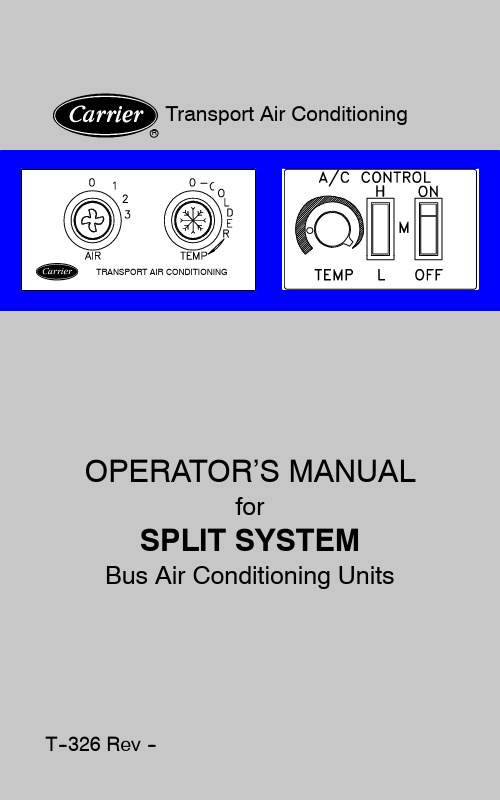
OPERATOR’SMANUALBUS AIR CONDITIONINGUNITSGEN IV&GEN VCONTENTSPage............................ Introduction1 .................................. Safety3 Unit/System Information4..............................1.1WHAT IS AIR CONDITIONING4..........................1.2SPLIT SYSTEM4................1.3SYSTEM DESIGNATIONS4.................1.4SYSTEM COMPONENTS4......1.5MODEL AND SERIAL NUMBER TAGS6........1.6SYSTEM REQUIREMENTS LABEL8..........................Unit Operation9.............2.1OPERATING INSTRUCTIONS9.2.2DRIVER’S CONTROL PANEL--STANDARD9...2.3DRIVER’S CONTROL PANEL--FLORIDA10..................2.4PRE--TRIP INSPECTION12 System Maintenance13........................................3.1Maintenance Schedule13.........................3.2Warranty/Service14 Index Index1 ...............................iI NTRODUCTIONS PLIT S YSTEM O PERATOR’S M ANUAL This guide has been prepared for the operator of Carrier Transport Air Conditioning systems.It contains basic instructions for the daily operation of the air conditioning system as well as safety information,and other information that will help you to maintain a comfort level for your self and your passengers.Please take the time to read the information contained in this booklet and refer to it whenever you have a question about the operation of your Carrier Transport Air Conditioning system.More comprehensive information can be found in the Split System Operation and Service Manual(T--299).This manual can be obtained from your Carrier Transport A/C dealer.Your air conditioning system has been engineered to provide long, trouble-free performance when it is properly operated and maintained.A comprehensive maintenance program will help to insure that the unit continues to operate reliably.Such a maintenance program will also help to control operating costs, increase the unit’s working life,and improve performance. Some Vehicles may require information from manuals supplied by the vehicle manufacturer or other special equipment suppliers.We urge you to review all these publications carefully.This will help you enjoy safe and trouble--free operation of your vehicle.When having your unit serviced,be sure to specify genuine Carrier Transicold replacement parts for the highest quality and best reliability.Carrier Transport Air Conditioning Dealers know your vehicle air conditioning system best and will ensure your complete satisfaction.To find the Dealer nearest you,go to and click on“Dealer Locator”,or refer to the Carrier Bus Stop Dealer Directory(62--10810)or contact the Carrier Transport Air Conditioning Technical Service Hot--Line1(800)450--2211.At Carrier Transport Air Conditioning,we are continually working to improve the products that we build for our customers.As a result, specifications may change without notice.1S AFETYYour Carrier Transport Air Conditioning system has been designed with the safety of the operator in mind.During normal operation,all moving parts are fully enclosed to help prevent injury.During all pre-trip inspections,daily inspections,and problem troubleshooting,you may be exposed to moving parts;please stay clear of all moving parts when the unit is in operation.Beware of unannounced starting of the unit.The unitmay cycle the fans and operating compressor unex-pectedly as control requirements dictate.Turn systemoff and disconnect battery power.REFRIGERANTThe refrigerant contained in the air conditioning system can cause frostbite,severe burns,or blindness when in direct contact with the skin or eyes.For this reason,and because of legislation regarding the handling of refrigerants during system service,we recommend that,whenever your unit requires service of the refrigeration system,you contact your nearest Carrier Transport Air Conditioning authorized dealer for service.3T--326U NIT/S YSTEM I NFORMATION1.1WHAT IS AIR CONDITIONINGAir Conditioning is the cooling,heating,dehumidification,and filtration of the air within the passenger compartment of a vehicle.1.2SPLIT SYSTEMA Split System normally includes an Evaporator(s),a Condenser(s) a Compressor(s)and interconnecting refrigerant hoses,fittings, and electrical harnesses and controls.A listing of the system components,along with specific data for each,is provided in Paragraph1.4.1.3SYSTEM DESIGNATIONSTie--In System--Is a Carrier evaporator and condenser connected to an existing OEM compressor and dash evaporator.The OEM radiator type condenser is normally removed.Max System--A Carrier system installed along with an existing OEM system.The systems operate independent of each other. Stand--Alone(Standard)System--All Carrier components installed on a vehicle.These can be either single or dual compressor systems.1.4SYSTEM COMPONENTS(Refer To Figure1-1)Return Air Thermostat/Sensor--The system may be supplied with a thermostat or thermistor.Both of these devices are temperature sensitive components which when activated,signals the Electro--Magnetic Clutch to engage/disengage.The return air thermostat is normally located in the drivers control panel while the return air thermistor is normally located in the return air flow of the evaporator assembly.Electro--Magnetic Clutch--The Electro--Magnetic clutch controls the operation of the compressor.When engaged,the compressor circulates refrigerant and provides cooling.Compressor--The compressor is a belt driven,high--pressure pump,which circulates the refrigerant through the evaporator and condenser.The operation of the compressor is controlled by the Electro--Magnetic clutch.Condenser--The condenser is normally located in the skirt or on the roof of the vehicle.Its primary function is to reject heat,which was transferred to the refrigerant by the evaporator from the passenger compartment of the vehicle.T--32645T--3262.Electro--Magnetic Clutch3.Discharge Line4.Condenser5.Filter Dryer/Sight Glass Assembly7.Evaporator8.Block Valve (TXV)9.Freezestat--(Coilfreeze--up thermostat)10.Suction Line Figure 1-1Component LocationsFilter/Dryer --The filter/dryer removes moisture and particulatematter from the refrigerant.Expansion/Block Valve --Meters the refrigerant flow into theevaporator coil.The majority of the Gen 4(Excel)and all Gen 5systems use a nonadjustable block valve with an 8°F superheat setting,which is preset at the factory.If you feel there is a problem with the block valve,do not attempt to adjust the valve,if needed,it should be replaced by an authorized Carrier Transport A/C service center.Evaporator --The evaporator is located in the interior of thevehicle.Its primary function is to transfer heat contained in the passenger compartment air,into the refrigerant,which is circulated by the compressor,through the evaporator coil.During this process the air is also filtered and dehumidified.Resistor --Resistors are used to control the speeds of thepermanent magnet evaporator blower motors.Pressure Switch--The systems use high and low pressure switches wired in series to control the power circuit of the compressor clutch relay.If either pressure switch opens, interrupting the circuit to the clutch relay,the operation of the compressor will stop.When conditions return to normal the switch will automatically reset and the compressor will resume operating. The switches are non--adjustable.Freeze--Up Thermostat--Freeze--up thermostats are used to prevent ice formation on the evaporator coil,which is an indication that liquid refrigerat is getting back to the compressor.Carrier Transport Air Conditioning systems use a freeze thermostat (freezestat)wired in series with the system pressure switches and thermostat/thermistor to control the operation of the compressor clutch.Refrigerant--A refrigerant is a material that is used to move heat from the passenger compartment to the outside air.It is a substance that gives up heat by condensing at high temperature and pressures and absorbs heat by evaporating at low temperatures and pressures.The heat transfer properties exhibited when refrigerant changes state is the foundation of the refrigerant cycle.1.5MODEL AND SERIAL NUMBER TAGSIn order to identify the air conditioning components you have,you will need to know the model number and serial number.All Carrier Transport Air Conditioning evaporators,condensers and compressors have a model/serial number tag located on the assembly.See Figure1-2for skirt mounted condenser data tag location,Figure1-3for the CM--7/11rooftop condensers data tag location,Figure1-4for GEN4(Excel)evaporator data tag location and Figure1-5for GEN5evaporator data tag location.Knowing these locations and the information on the data tags will aid you inprocedures.identifying the correct serviceT--32667T--326Figure 1-3Roof MountedCondensersEM--9LocationFigure 1-4Rear/Side Mounted Gen IV Evaporators NOTEThe EM--9evaporator data tag is located on the side oftheevaporator assembly,not between theblower assemblies.Figure 1-5Rear/Side Mounted Gen V Evaporators8T--3261.6SYSTEM REQUIREMENTS LABELThe system requirements label (See Figure 1-6)is conveniently located within the vehicle’s engine compartment.This label,when properly completed by the installer,will give the servicing technician the refrigerant and oil charge(s),evaporator(s),condenser(s),and compressor(s)serial numbers,the drive belt(s)number,mount kit number,the date of installation and theinstaller.Figure 1-6System Requirement Label9T--326U NIT O PERATION2.1OPERATING INSTRUCTIONSBefore attempting to operate the system,power must be available from the vehicle battery.If the engine is not running,start the engine.Most systems will not operate unless a signal is received to the controller from the vehicle ignition.Carrier Transport Air Conditioning system’s can be supplied with two different type manual controls.the Standard Manual Control and the Florida Control123451Control Panel Housing 2Nameplate (Switch Mounting)3Thermostat Control4Fan Speed Switch (3Speed or Variable)5Ambient Air Sensor (Thermostat)Figure 2-1Drivers Control Panel --Standard2.2DRIVER’S CONTROL PANEL --STANDARDThe standard Drivers Control Panel (See Figure 2-1),consists of an evaporator fan speed switch (three speed or variable)and an adjustable thermostat.The drivers control panel is normally located within easy reach of the driver.On larger bus applications there could be two separate air conditioning system driver control panels.One for each system.There will be some applications where the switch mounting plate, thermostat and fan speed switch are mounted in the drivers area without the control panel housing.On other applications the vehicle manufacturer(OEM)will supply different type controls for the air conditioning system.Refer to OEM technical manual for operating instructions.2.2.1Fan Speed Switch(three speed or variable)Turning this switch clockwise will energize the evaporator and condenser fan motors.The compressor clutch will also be energized if the thermostat calls for cooling(see thermostat control operation).Three Speed--The standard fan speed switch has four settings, Off(0),Low(1),Medium(2),and High(3)speed operation.This switch controls the operation of the system and the evaporator blower(s)by energizing the appropriate circuits and relays located on the electrical control panel.Variable Speed--Certain applications may be fitted with a variable speed control switch instead of the standard three speed switch. This switch controls the speed of the evaporator motors by varying the supply voltage.2.2.2Thermostat ControlThe thermostat controls the temperature within the passenger compartment by switching system components on and off. Rotate the potentiometer switch knob to the right(clockwise)for maximum cooling.Rotate the potentiometer switch knob to the left (counterclockwise)for less cooling.2.3DRIVER’S CONTROL PANEL--FLORIDA(TEMPCON) This control panel(See Figure2-2)is normally used in school buses located within the state of Florida,but not limited to that area. This controller is wired to an electrical control board.The controller consists of:a.ON/OFF Switchb.Fan Speed Switchc.Potentiometerd.In--Line Fuse(Behind Controller)2.3.1ON/OFF SwitchPower is supplied to the controller,through an in--line fuse(see Figure2-3)from a12VDC ignition source originating from the vehicle.The controller will not operate until the ignition switch is activated.T--32610Move the ON/OFF switch to the ON position.A green light will illuminate indicating that the controller has power.At the same time the evaporator fans will operate in either Low,Medium or High speed,depending on the Fan Speed switch location.123451Face Plate2Green Light3Rocker Switch,2Position,ON/OFF4Rocker Switch,3Position,LOW--MED--HIGH5Thermostat Control(Potentiometer)Figure2-2Switch Assembly(TEMPCON)2.3.2Fan Speed Switch--3SpeedThe evaporator fan speeds can be adjusted by pushing the rocker switch to the desired position:a.H=High Speedb.M=Medium Speedc.L=Low SpeedWhen the evaporator fan speed switch is positioned at the desired speed,a signal is sent to the corresponding fan speed relay located on the electrical circuit board.2.3.3Thermostat ControlThe thermostat control potentiometer has an operating range of60 to85degrees F.Rotate the potentiometer switch knob to the right(clockwise)for maximum cooling.Rotate the potentiometer switch knob to the left (counterclockwise)for less cooling.11T--32612T--326Fuse 3AmpIn--Line Fuse &HolderFuse CoverFigure 2-3In--Line Fuse &Holder (3Amp)2.3.4In--line FuseThe controller is protected by a 3Amp ATO type in--line fuse (Figure 2-3).To replace the fuse do the following:a.Make sure ignition power is off.b.Grasp fuse cover at finger grips and lift off cover.c.Remove fuse and check if fuse is defective.d.Replace if needed.e.Push fuse cover back on to in--line holder.f.Restore ignition power and place ON/OFF switch to ON.2.4PRE--TRIP INSPECTIONAfter starting system operation,allow system to stabilize for ten to fifteen minutes and check for the following:1.Listen for abnormal noises from the vehicle engine,evaporator and condenser areas.2.Ensure evaporator and condenser fans are operating.3.Ensure water is not dripping from the evaporator or air ducts.4.Check for reduced airflow.This is normally caused by dirty or clogged evaporator filters.S YSTEM M AINTENANCE3.1M AINTENANCE S CHEDULESYSTEMON OFFOPERATIONa.Daily MaintenanceX XX Pre--trip inspection--after starting.(Refer to para-graph2.4)Check tension and condition of drive belts.b.Weekly MaintenanceX X Perform daily inspectionCheck condenser,evaporator coils and return air filters for cleanlinessc.Monthly MaintenanceX XXXXXPerform weekly inspectionClean or replace Evaporator return air filtersInspect Condenser coil fins--Clean when neces-saryInspect refrigerant hoses and fitting connections.Inspect electrical harness and connectionsCheck battery voltage--System operates efficiently at13.5voltsd.Quarterly InspectionXXXXXX Inspect Evaporator(s)coil fins(heater coil if installed)Clean if needed.Check blower operation.Check current draw and voltage of system compo-nents including fan motors.Check that all compressor mounting brackets and hardware are tight.Tighten and torque to proper specifications.Check hose and harness under vehicle for proper support and protectionCheck Evaporator drain lines.13T--326SYSTEMON OFFOPERATION(Continued) e.Semi--Annual Inspection and MaintenanceXXXXXXX Check system pressures.Check refrigerant in sight glass.Check element in the the sight glass.(Green is dry --Yellow is wet)Inspect condenser fan blades.Open bus heater valves(In winter).Close bus heater valves(In spring).Remove or install optional condenser winter guard kit.f.Annual Inspection and MaintenanceX XXXXInspect electrical panel and terminals.Clean ifneeded with a high-grade cleaner specifically for-mulated for this purpose.Inspect Evaporator drain pan.(Clean if needed)Check pressure switch operation.Check evaporator roof mounting and sealing.Check condenser mounting,fan guards,andscreen/grill.3.2W ARRANTY/S ERVICEThank you for choosing a Carrier Transport Air Conditioning system for your vehicle.We want to assure you of our continuing interest in your pleasure and satisfaction with your air conditioning system. Remember,if you have a question or concern and need help, contact your nearest Transport Air Conditioning Dealer.To find the Carrier Transport Dealer nearest you,go to and click on“Dealer Locator”,or refer to the Carrier Bus Stop Dealer Directory(62--10810),or contact the Carrier Transport Air Conditioning Technical Service Hot--Line1(800)450--2211.for the center nearest you.14T--326I NDEXCClutch--Electro--Magnetic,4 Compressor,4 Condenser,4Control Panel--Florida,10 Control Panel--Standard,9EEvaporator,5FFilter/Dryer,5Fuse,In--Line,12IIntroduction,1M Maintenance Schedule,13 Max System,4Model Tag,6OOperating Instructions,9PPre--Trip Inspection,12R Refrigerant,3,6 Resistor,5SSafety,3Sensor--Return Air,4 Serial Tag,6Split System,4Stand--Alone System,4 Switch--Fan Speed,10,11 Switch--ON/OFF,10 Switch--Pressure,6 System Components,4 System Designations,4 System Maintenance,13 System Label,8TThermostat--Freeze--Up,6 Thermostat--Return Air,4 Thermostat Control,10,11 Tie--In System,4Index1I NDEX(C ONTINUED)UUnit Information,4Unit Operation,9VValve--Expansion/Block,5WWarranty/Service,14What Is Air Conditioning,4Index2Carrier Transicold Division, Carrier CorporationTransport Air Conditioning Group P.O.Box4805Syracuse,N.Y.13221U.S A 。
精密空调控制器操作手册

行间空调电气控制说明书版本管理目录1系统配置 (4)2系统参数 (4)3.电气配置 (4)4.输入/输出定义 (4)4.1模拟量输入 (4)4.2数字量输入 (5)4.3数字量输出 (6)4.4模拟量输出 (6)5.控制功能 (7)5.1.运行模式 (7)5.2室内风机控制 (7)5.3室外风机控制 (7)5.4提升泵 (7)5.5压缩机控制 (8)5.5保护功能 (8)6.触摸屏的设定 (10)6.1主菜单 (10)6.2报警记录 (10)6.3菜单 (11)1系统配置2系统参数3.电气配置4.输入/输出定义4.1模拟量输入4.2数字量输入4.3数字量输出4.4模拟量输出5.控制功能5.1.运行模式制冷:当温度>设定温度+制冷温差的百分比开始制冷,当温度下降到设定温度-制冷温差的百分比制冷终止,控制的方式是比例控制。
加热:当温度<设定温度-制热温差百分比开始制热,当温度>设定温度+制热温差百分比停止制热,比例控制加热时,根据温度控制电加热,可选二进制式控制和分步控制。
加湿:室内湿度<湿度设定点-湿度偏差,加湿输出,打开加湿接触器;室内湿度>加湿设定点+湿度偏差,关闭加湿功能,加湿接触器关闭,加湿时根据湿度比例控制加湿器,通过MODBUS给CPY信号。
除湿:制冷除湿,当环境湿度>湿度设定点+湿度变差偏差值开压缩机,同时供液电磁阀开;默认送风湿度控制,可选回风湿度控制。
除湿时,压缩机根据预设频率运行,默认80%;送风机的风速是60%(可调),当然如果除湿温度过低,电加热会打开,进行温度的补偿,达到控制湿度的目的。
5.2.室内风机控制根据冷通道远端温度比例调节风速,如NTC都存在且正常,制冷时以温度高的NTC来控制,制热时以温度低的NTC来控制,只有这2个NTC温差超过1℃时,才需要切换;如果只有1个NTC正常,以这个NTC来控制。
除湿时根据预设固定风速运行,默认60%。
设最高/最低风速限制。
汽车空调控制器原理
汽车空调控制器原理
汽车空调控制器是一种使用电子技术控制汽车空调系统的设备。
它通过传感器检测车内外的温度和湿度,根据设定的参数来控制空调系统的工作。
空调控制器的工作原理主要包括以下几个方面:
1. 温度检测:空调控制器通常内置有温度传感器,可以实时监测车内温度。
当车内温度高于设定温度时,控制器会发出指令启动空调系统。
2. 湿度检测:除了温度,空调控制器还可以通过湿度传感器检测车内的湿度情况。
根据设定的湿度范围,控制器可以调节空调系统的湿度控制功能。
3. 控温控湿:根据车主设定的温度和湿度值,空调控制器会计算出当前环境下最合适的出风温度和湿度。
然后,通过控制空调系统中的压缩机、风扇等元件,调节出风口的温度和风速,以达到舒适的空调效果。
4. 微处理器控制:空调控制器内部通常集成有微处理器,通过这个微处理器,控制器能够实现各种功能的设定和控制。
通过控制面板上的操作按钮,车主可以设置温度、湿度、风速等参数,控制器会根据这些设定来运行空调系统。
5. 故障诊断:空调控制器还具备故障检测和诊断功能。
当空调系统出现故障时,控制器会根据传感器的反馈信息,判断故障
原因并显示相应的故障代码。
这样,维修人员可以根据故障代码进行精确的维修。
总的来说,汽车空调控制器是通过检测温度和湿度、控制压缩机、风扇等元件,调节空调系统的工作,以实现舒适的空调效果。
它是整个空调系统中的核心部件,能够提供高效、智能化的空调控制功能。
汽车空调控制器介绍中英文(2023最新版)

汽车空调控制器介绍中英文汽车空调控制器介绍⒈概述汽车空调控制器是一种用于控制车辆空调系统的电子设备。
它通过对车辆空调系统的各种参数进行监测和调节,实现空调温度、风速、空气流向等方面的控制,提供舒适的驾驶环境。
⒉主要功能⑴温度控制空调控制器可以通过监测车内温度传感器的信号,并与设定温度进行比较,自动调节空调系统的出风温度,确保车内温度始终保持在设定范围内。
⑵风速控制通过控制空调系统中的风机,在不同的环境温度和需求下,调节空调系统的风速,提供适宜的空气流通,提高乘坐舒适度。
⑶模式选择空调控制器提供多种模式选择,如制冷模式、制热模式、除霜模式等。
用户可以根据不同的季节和需求选择合适的模式,满足不同的驾驶需求。
⑷空气流向控制空调控制器能够控制空调系统中的风门和排风门,调节空气流向,让空气均匀分布到车内不同位置,满足乘客的需求。
⑸微矩阵控制一些高级空调控制器还具备微矩阵控制功能,通过细微的调节控制,使空气流动更加均匀,减少温度差异和噪音,提升舒适度。
⒊操作界面汽车空调控制器通常采用触控屏幕或按钮控制界面。
触控屏幕界面提供直观的图形化显示和操作,方便用户进行设置和调节。
按钮控制界面则通过按钮和旋钮的方式进行操作。
⒋附件说明附件1:汽车空调控制器操作手册附件2:汽车空调控制器技术规格书⒌法律名词及注释⑴汽车空调系统:车辆中用于调节车内温度和湿度的系统。
⑵温度传感器:一种感知环境温度变化并输出电信号的器件。
⑶风速控制:通过调节空调系统中的风机的运行速度,控制空气的流通速度。
⑷模式选择:根据不同的需求和季节选择合适的工作模式。
⑸风门:控制空调系统中空气的流向,将空气送到不同的区域。
⑹微矩阵控制:通过微小的调节控制,提升空气流动的均匀性和舒适度。
冷王空调控制器资料

ClimaAIRE II 控制器
4---风机速度选择键
自动风机速度:风机按照温度设定点和乘舱情况自动 控制 风机高速 风机中速 风机低速
ClimaAIRE II 控制器
5---新风选择键
自动控制乘舱内的新鲜空气 新风门打开 新风门打开50% 新风门关闭
ClimaAIRE II 控制器
6---温度设定旋钮
辅助输出----通用
ClimaAIRE II 控制器
设置控制器
控制器必须处于关闭状态 同时按 键和 键3秒钟,直至显示“t-1”。 按 键滚动菜单选项:
“t-1”---测试模式1 “rt”---继电器测试 “Pr”---程序号设置和读取软件版本 “Co”---通讯模式 “CAL”---温度传感器校准 “SEt”---控制器设置 “rAL”---报警的读取和清除 “rES”---控制器复位
ClimaAIRE II 控制器
当显示“Pr”时,按 键确认。首先显示软件版 本号3秒钟,之后显示程序号。
要想改变程序号,按 键或 键达到所需值。程 序号见附件。
当所需程序号显示时,按 键确认储存在控制器 中。
当显示“SEt”时,按 键确认,然后滚动菜单选 项:
“Ab”---环境开关点(0~15℃) “Un”---电源电压(未使用) “LoS”---设定点最小值(15~30℃)
机速度控制---EFL,EFH,EFM 冷凝器风扇输出 PWMC 压缩机离合器---CR 增压泵----BP 加热电磁阀---MCV1
ClimaAIRE II 控制器
地板加热电磁阀---MCV2
新风门100%---DM1
新风门50%---DM2
SM1,SM2,SM3---控制伺服电机
警。所有报警会被显示3秒钟,最后将提示你是否 清除所有报警。 按 键清除所有报警或按 键关闭控制器保留 所有报警。如果所有报警是通过操作面板清除的, 那么这些报警还可以通过PC再次读到。
C1002控制器使用说明书

STULZ精密空调简易操作资料C1002控制器中文操作资料空调常见故障判断及处理STULZ C1002精密空调操作资料1STULZ C1002精密空调操作资料2STULZ C1002精密空调操作资料3STULZ C1002精密空调操作资料4STULZ C1002精密空调操作资料5STULZ C1002精密空调操作资料6STULZ C1002精密空调操作资料空调常见故障判断及处理1、更换热保护器2、清洗或更换滤网3、调整或更换皮带1、热保护器坏2、过滤网脏3、风机皮带太松电加热故障HEA 1、倒换相序2、检查三相电源是否正常3、闭合空开/更换保险管4、调整皮带,清洗滤网5、调整、更换气流开关6、改造回风1、AC 电源反相2、AC 电源缺相/不正常3、风机空开未闭合/保险管坏4、皮带松,滤网脏5、气流开关失灵6、回风不好气流报警FLO11、查漏后补氟里昂2、更换膨胀阀3、清洗过滤网4、改造回风5、更换低压保护开关6、更换干燥过滤器7、更换管路电磁阀或线圈8、修改设定值1、A/C 系统缺氟漏氟2、膨胀阀失灵3、过滤网脏4、回风不好5、低压保护开关坏6、干燥过滤器脏堵7、管路电磁阀或线圈坏8、温度设置太低低压报警LOP1清洗或更换过滤网1、清洗室外机2、更换室外风机3、检查线路及开关4、高压开关复位5、更换高压保护开关故障处理过滤网脏1、室外机太脏2、室外风机堵转3、室外机无电源4、高压开关未复位5、高压保护开关坏原因过滤网脏堵FIL 压缩机高压报警HIP1报警内容7STULZ C1002精密空调操作资料8STULZ C1002精密空调操作资料9。
Thermo King 公司的巴士空调控制器说明书

C O N T R O L S O L U T I O N S F O R B U S H V A C— to t a l co ntrol, at y o ur f inger-tip s —FEATURE-RICH CONTROLLERSINTUITIVE INTERFACEHIGH-LEVEL ACCURACY & RELIABILITYDifferent applications need different control solutions, and Thermo King’s CANAIRE®, ClimaAIRE™ and FrontAIRE™ controllers have been developed to meet those needs. Thousands of hours of real-life testing ensure that the controllers are not only high-performing but also durable under the toughest of conditions.Thermo King’s range of bus HVAC controllers allows the operator to easily and accurately control the climate in his vehicle and ensure the comfort of his passengers, independent of outside conditions.Easy to read displays present just enough information to monitor temperature set-point and system parameters. Touch buttons and analogue dials offer an intuitive interface for fine tuning of cooling, heating and ventilation. Diagnostic features are built-in to reduce maintenance and repair costs.Each bus is different in terms of structure, ambient conditions, operator and passenger needs. Thermo King not only has a wide portfolio of different driver panels but also the expertise to customize the software for most streamlined HVAC functionality in a bus fleet.Control solutions for bus HVACTotal control, at your finger-tipsEase of useAccuracy & reliabilityCustomised solutionsRely on the most sophisticated controller in the industry CANAIRE®Expandable controller for multi-zone, multi-function managementThe CANAIRE® is flexible, modular and expandable HVAC control system. It can be used with the unit only, or expandedto include floor heating, driver’s area and auxiliary pre-heater. All these are controlled from one easy-to-use, intuitive HMI (human machine interface) panel. There are three HMI options to choose from in the CANAIRE® range to suit the specific needs of an installation. The controller uses CAN (Controller Area Network) to communicate with the I/O modules for the expanded functions as well as with the vehicle if required.Features• Driver panel available also in IP54 version• One integrated driver’s panel for management of driver and saloon areas• Expandable with up to three main modules to control different zones (e.g. articulated bus, double-decker)• Easy to read, easy to understand graphic LCD display• Ambient and two set-point temperature displays for driver and saloon• Fuel saving features including screw compressor unloader• Choice of automatic or manual control of temperatures, blower speeds and fresh/recycled air• Two independently configurable CAN ports => CAN gateway function of the Main control module for safe interfacing between Thermo King HVAC and the on-board bus system ( ISO11898 and/or SAE J1939)• Real time clock built-into driver’s panel• Diagnostic tool directly connected via CANClimaAIRE I D™Ease of use for climate controlThe ClimAIRE I D eliminates the driver interaction and interference with the HVAC system, allowing uniform fleet operation conditions. The controller allows the set point to be predetermined and fixed throughout the operation.100% fresh air can be selected where appropriate and there is a choice of four operating modes: ventilation, cool, heat and auto. The ClimaAIRE™ is also a sophisticated diagnostic tool, displaying alarms. It can be linked to a PC monitor to display output.Features• Two-digit display with automatic brightness controlanalogue sensors• Four operating modes: ventilation, cool, heat, auto orreheat• Fully automatic system with blower and fresh airdamper control• Full diagnostic functions and PC monitor output• Directly interchangeable with previous model:same functions, same mounting slotin sustainable transport temperature control solutions. Thermo King has been providing transporttemperature control solutions for a variety of applications, including trailers, truck bodies, buses, air,shipboard containers and railway cars since 1938.For further information, please contact:Find your nearest dealer onThermo King Europe – Lenneke Marelaan 6, B-1932 Sint-Stevens-Woluwe, Belgium© 2020 Thermo King Europe TK 80043 (08-2020)-EN。
企业信用报告_冷王集装箱温度控制(苏州)有限公司

5.1 被执行人 ....................................................................................................................................................10 5.2 失信信息 ....................................................................................................................................................10 5.3 裁判文书 ....................................................................................................................................................10 5.4 法院公告 ....................................................................................................................................................10 5.5 行政处罚 ....................................................................................................................................................10 5.6 严重违法 ....................................................................................................................................................11 5.7 股权出质 ....................................................................................................................................................11 5.8 动产抵押 ....................................................................................................................................................11 5.9 开庭公告 ....................................................................................................................................................11
冷王SLXi系列操作手册说明书

SLXi-100, 200, 300, 400SLXi-300 Whisper ProSLXi Spectrum,and SLXi Spectrum Whisper Pro操作手册(2018年第1次修订) Copyright© 2018, Thermo King Corp.目录介绍 (3)基本信息 (3)普通咨询及机组保养 (3)急救及安全 (6)制冷剂 (6)制冷剂润滑油 (6)制冷剂信息 (7)安全注意事项 (7)自动开/关操作 (8)电气危害 (8)机组描述 (9)概述 (9)冷王SR-3控制器 (10)标配远程监控 (11)SR-3控制面板基本操作 (15)循环-检测启/停控制 (20)除霜 (20)电子节流调节 (20)医药 (20)养护 (22)行车前人工检查(启动机组前) (22)装载 (24)检查后装载 (24)检查和维修周期 (26)规格 (27)引擎TK486V (27)电气控制系统 (28)备用电机(仅50型号) (28)备用电源要求 (28)冷王 BULE BOX (28)安全标贴及序列号 (29)安全标贴 (29)系列号标贴 (32)介绍基本信息此手册的发行目的是提供信息。
本手册中的信息并未囊括一切,或者说并未包括所有的方面。
若需要进一步的资料,请查阅您的冷王维修电话簿,找出您当地的冷王代理商的地址和电话,与您当地的冷王产品代理商联系。
所有的维修要求,无论大小,均应由冷王代理商处理。
定期进行行车前检查和行车途中检查将会把途中的故障概率降至最低。
定期维护保养计划也将会帮助您的机组保持最佳工作状态(参照本手册中的“保养检查计划”)。
普通咨询及机组保养普通咨询,请联系您当地冷王代理商。
请访问来查找您当地代理商。
或者通过冷王维修电话簿查询联系方式。
紧急援助Thermo Assistance是一个多语言沟通工具,旨在帮助您与冷王授权代理商取得直接联系。
Thermo Assistance只能在机组抛锚及需要维修援助时才能使用。
汽车空调控制器介绍中英文(二)

汽车空调控制器介绍中英文(二)引言概述:
汽车空调控制器是现代汽车中必不可少的一个控制系统,它负责调节和控制车内的温度和湿度。
本文将介绍汽车空调控制器的工作原理、组成部分以及其在汽车中的应用。
正文内容:
I. 汽车空调控制器的工作原理
1. 温度传感器的作用及原理
2. 湿度传感器的作用及原理
3. 控制器的工作方式及算法
II. 汽车空调控制器的组成部分
1. 控制面板的功能和特点
2. 控制单元的功能和特点
3. 传感器的类型和使用方法
4. 调节阀门的作用及原理
5. 状态指示灯的显示方式
III. 汽车空调控制器在汽车中的应用
1. 车辆类型对空调控制器的要求
2. 汽车空调系统的结构及与空调控制器的关系
3. 空调控制器对车内舒适度的影响
4. 空调控制器对能源的消耗的影响
5. 空调控制器与车载信息系统的整合
IV. 汽车空调控制器的性能评价指标
1. 温度调节精度的评估方法
2. 湿度调节精度的评估方法
3. 控制响应速度的评估方法
4. 能耗评估方法
5. 故障诊断能力的评估方法
V. 汽车空调控制器的发展趋势
1. 智能化技术在空调控制器中的应用
2. 增加功能和附加值的发展方向
3. 节能环保的要求和措施
4. 与其他车载系统的协同发展
5. 消费者需求对空调控制器的影响
总结:
通过本文的介绍,我们了解到汽车空调控制器是如何工作的,以及它的组成部分和应用。
我们还了解到了空调控制器的性能评价指标以及未来发展的趋势。
随着智能化技术的发展和消费者对舒适度和能效的要求不断提高,汽车空调控制器在汽车行业中的作用将愈发重要。
冷王制冷机组参数
冷王制冷机组参数1.引言1.1 概述冷王制冷机组参数是指用于冷王制冷机组的一系列参数。
冷王制冷机组是一种常用的制冷设备,广泛应用于各种工业和商业场所。
冷王制冷机组参数包括了机组的工作压力、流量、温度等信息。
这些参数对于机组的运行状态和性能有着重要的影响。
在设计和选择冷王制冷机组时,合理的参数选择是十分重要的。
不同的使用环境和需求会对机组参数有所不同。
因此,准确把握冷王制冷机组参数的概念和要点,对于确保机组的运行效果和节能效果具有重要意义。
本篇文章将介绍冷王制冷机组参数的概述,并重点阐述几个关键要点。
通过深入了解和研究这些参数,我们可以更好地理解冷王制冷机组的工作原理和性能特点,进而优化其运行和调整。
同时,也能为今后的研究和应用提供参考和指导。
接下来的章节将分别对冷王制冷机组参数的概述、要点1和要点2进行详细介绍。
通过对这几个方面的讨论,我们可以全面地认识和了解冷王制冷机组参数的重要性和实际应用。
最后,在结论部分,将对本文的内容进行总结,并对冷王制冷机组参数的意义和未来展望进行探讨。
文章结构部分的内容应包括对整篇文章的组织和框架进行概述和介绍。
下面是一个示例:1.2 文章结构本文主要介绍冷王制冷机组的参数,并对其进行详细分析和探讨。
文章分为引言、正文和结论三个部分。
具体结构如下:引言部分将概述文章的背景和目的,以及本文所要讨论的冷王制冷机组参数的重要性和实际应用价值。
正文部分将详细介绍冷王制冷机组参数的概述、要点1和要点2。
在2.1节中,我们将对冷王制冷机组参数进行整体概述,包括其基本定义、分类、常见测量方法等内容。
在2.2节和2.3节中,我们将侧重探讨冷王制冷机组参数的关键要点,从多个角度进行分析和解释。
结论部分将对本文的主要内容进行总结,并指出冷王制冷机组参数的意义和展望。
在3.1节中,我们将对本文的主要观点和结论进行概括性总结。
在3.2节中,我们将展望冷王制冷机组参数在未来的发展方向和应用前景。
c6000中文说明书-精密空调机组微处理控制器操作手册
Stulz C6000控制器第52索引精密空调机组微处理控制器操作手册目录页码简介 (3)安全须知 (3)页码代号 (3)控制器说明 (4)操作界面 (6)控制器操作 (7)菜单对话框和参数说明启动窗口.............................................................................. .. (8)标准窗口 (9)“信息”菜单..................................................................... ......... .. 10“控制”菜单................................................................................. .... .12“服务”菜单................................................................................. . (17)功能说明监控器操作.................................................................................... (26)GE操作 (27)干冷器操作 (28)两套系统的顺序控制 (29)总线顺序控制 (31)数字自控连接 (32)备份运行 (34)传感器的故障 (36)信号....................................................................................... (37)控制器出厂时的设........................................................................ (40)控制图....................................................................................... (42)硬件说明控制器.......... .. (44)下载新软件 (45)标准I/O板 (48)扩展I/O板 (52)温度/湿度传感器 (54)系统配置带I/O板的C6000的电路图 (55)第一模块带监控器的C6000的电路图 (55)第二模块带监控器的C6000的电路图 (56)打印机连接 (57)电脑连接 (57)故障排除 (58)信息水平概述 (59)控制水平概述 (60)服务水平概述 (61)简介本手册对控制器的操作和设计进行了说明,控制器组成了空调单元的中央控制站,整个空调都是由控制器控制和检测的。
空调控制器 说明书

空调控制器使用说明书在安装使用控制器之前,详细阅读该使用说明书!广州英联电子科技有限公司版权所有,翻印必究目录一、概述 (4)1.1、YL43触摸屏简介 (4)1.2、YL224控制板简介 (4)二、接线 (4)2.1、水冷冷水机组接线图 (5)2.2、水冷冷热机组接线图 (6)2.3、风冷冷水机组接线图 (7)2.4、风冷热泵机组接线图 (8)四、机组运行 (9)4.1、开机页面 (9)4.2、主页面 (9)4.3、用户参数页面 (11)4.6、周期定时设定 (11)4.7、状态查看页面 (12)4.8、当前故障查看 (12)4.9、历史故障查看 (13)五、系统设置 (13)5.1、机组设置 (14)5.2、使用期限设定 (14)5.3、探头设置 (15)5.4、时间设置页面 (15)5.5、IO信号配置 (16)5.6、温度保护点设定 (16)5.7、除霜参数 (17)5.8、冷凝风机或冷却塔风扇参数 (18)六、维护设置 (19)6.1、温度校准页面 (19)6.2、温控设置 (20)6.3、压缩机设置 (20)七、控制逻辑 (21)7.1、开机操作 (21)7.2、停机操作 (21)7.3、能量调节 (21)7.4、除霜逻辑 (22)7.5、冷凝风机 (23)7.6、冷却塔风扇 (23)八、故障处理 (25)8.1、故障显示 (25)8.2、故障判断原则和检测时机 (25)九、版本记录 (28)使用说明书一、概述本空调控制器是广州英联电子科技有限公司专为空调冷冻领域设计生产的一种可编程控制器,整套控制器由YL43A触摸屏+YL226控制板组成。
1.1、YL43触摸屏简介1、输入电源DC24V 0.5A。
2、采用先进的32位ARM处理器,性能远高于同行业中使用的单片机。
3、电路板采用四层板设计,元件SMT表面贴装工艺,结构紧凑,发热量低,抗干扰能力强。
4、带2个485通讯口,一个用于与YL226控制板通讯,另一个用于同PC通讯。
冷源科技 中央空调万能通用型控制器 使用说明
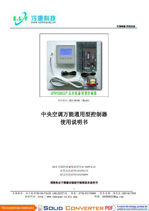
空调维修,因我而易!1程序版本:ELY/08-06 /(Rev01)中央空调万能通用型控制器使用说明书EL Y 冷源科技★版权所有@2009-8-22业务电话**************图文传真**************请您务必于维修安装前仔细阅读本说明书空调维修,因我而易!2中央空调万能通用型控制器说明书QTM120C2户式冷水机组一、产品简介本产品基于中央空调维修的特点并结合麦克维尔、开利、约克、特灵等主流空调品牌的产品控制技术及系统匹配参数设计开发。
内置先进的系统过冷度、过热度智能匹配程序。
集成所有空调系统保护电路,完全通用市场上绝大多数中央空调品牌。
QTM120C2完美通用于所有品牌户式冷(热)水机组及各种不同类型小型风冷冷(热)水机组空调产品。
二、产品功能✧单个主板可控制1-2台压缩机,2个四通阀,2个散热风机,2台循环水泵✧工作模式:制冷/制热/自动运行/待机防冻/智能除霜✧支持七组定时开关机功能✧压缩机再启动保护功能✧压缩机过载保护功能✧感温器缺失自动检测报警功能✧先进的系统过冷度/过热度智能匹配功能✧冷媒泄露自动检测功能✧智能能量控制,负荷匹配功能✧根据负荷智能调整压缩机平均磨损功能✧TTL 通讯接口,连线距离<30M三、控制面板操作说明出水3空调维修,因我而易!4注:通过开/关机键对机组启停控制时,是根据当前机组状态,取反控制,即如是开机则执行关机。
多色彩背光LCD 显示,线控器能接受面板按键和红外遥控控制。
用来控制小型冷热水机组。
它支持以下功能控制: 模式——制冷,制热独立的制冷模式温度设置和制热模式温度设置 进水/出水温度显示 实时时间显示 实时开/关 手动除霜 按键锁定功能不同的控制参数设定,如:除霜终止温度等 上电默认关机或最后运行状态选择 远程遥控开/关 室外风机速度显示永久性记忆——重新上电时保持掉电前的设置 多色彩背光显示 多种错误代码读出 按键输入时蜂鸣器提醒 无线遥控控制掉电时电池支持实时时钟运行1)通电设置通电后,系统从永久记忆体中获取最新设定和系统状态信息:a)模式空调维修,因我而易!5b)制冷和制热模式温度设定c)定时开/关机设定d)密码和运行时间设定e)回水或出水温度显示f)系统状态(开/关)g)上电默认关机或最后运行状态h)按键锁定状态i)系统运行时间2)模式按〈模式〉键将循环实现从制冷到制热模式的转换(模式切换需在关机状态下)。
柴油冷气系统空调产品说明书

0812Submittal Data—PERFORMANCE DATA—CERTIFIED DIMENSION PRINTS—CERTIFIED ROOF CURBDIMENSION PRINTS—SERVICE OPTION DIMENSIONPRINTSCopyright2008Carrier Corp.S7310W.Morris St.S Indianapolis,IN46231Printed in U.S.A.Edition Date:5/08 Manufacturer reserves the right to change,at any time,specifications and designs without notice and without obligations.Catalog No:48TC---02SB Replaces:NEWJob Data:_________________________________________Location:_________________________________________________Buyer:____________________________Buyer P .O.#____________________________Carrier:___________________________Unit Number:_____________________________________Model Number:____________________________________________Unit Designation:_____________________________________________________________________________________________Performance Data Certified By:_________________________________________________________________________________This product has been designed and manufactured to meet Energy Star ®criteria for energy efficiency.However,proper refrigerant charge and proper air flow are critical to achieve rated capacity andefficiency.Installation of this product should follow all manufacturer’s refrigerant charging and air flow instructions.Failure to confirm proper charge and air flow may reduce energy efficiency and shorten equipment life.DESCRIPTION48TC units are high--efficiency,single--packaged electriccooling,gas heating units that are pre--wired andpre--charged with Puron R (R--410A)HFC refrigerant.Theunits are factory tested in both heating and cooling modes.These units meet the ASHRAE 90.1--2004and EnergyStar minimum efficiency levels.STANDARD FEATURESBase UnitS Puron (R--410A)HFC refrigerantS ARI certified efficiency levels up to 11EER S Rated in accordance with ARI Standard 360S Designed in accordance with Underwriters’Laboratories Std 1995and listed by UL and UL,Canada S Single--stage capacity control S Non--corrosive composite sloping design;side or center drain condensate pan.Meets ASHRAE Standard 62S Cooling operating range from 40_F up to 115_F.Below 40_F requires Winter Start KitS Convertible from vertical to horizontal airflow for slab mounting S Two--inch disposable return air filters S Thru--the--bottom power and gas entry capabilityS Single point gas and electric connections S 24--volt control circuit protected with resettable circuit breaker S Belt drive,constant torque,permanently lubricated evaporator--fan motorS Totally enclosed condenser motors with permanently lubricated bearings S Low--pressure and high--pressure switchesSFull perimeter base rail with built--in rigging adapters and forktruck slotsCabinetS Access panels with easy grip handles and NO--STRIP screwdevices S Pre--painted exterior panels and primer--coated interior panelstested to 500hours salt spray protection S Fully insulated cabinet S Tool--less filter access doorRefrigerant SystemS Acutrol t refrigerant metering system S Liquid line filter drierS Scroll compressors with internal line--break overload protectionSCopper tube,aluminum fin coils with optional corrosion resistant coilsS Removable gauge line plugs for reading refrigerant pressure with unit panels in placeGas HeatS IGC solid--state gas heat exchanger control for on--boarddiagnostics,anti--cycle protection,LED error code designation,burner control logic and energy saving indoor fan motor delay S Gas efficiencies up to 82%S Induced draft combustionS Redundant gas valve,with up to 2stages of heating S Flame roll--out safety protectorS Solid--state electronic direct spark ignition systemStandard WarrantyS 10--year heat exchanger S 5--year compressor S 1--yearpartsPERFORMANCE DATAUnit Operating Weight________________________lb CoolingGross Total Capacity:_______________________Btuhat Condenser Air Temperature_______________F Gross Sensible Capacity:_____________________Btuh Compressor Power Input:__________________________kW Indoor Entering db______________F wb______________F Airflow_________External Static Pressure_________in.wg Indoor Fan Motor Size____________________________Hp Exhaust Fan Motor Size__________________________Hp Curb Weight____________________________________lb HeatingHeating Capacity:Stage1_________________________________________Btuh Stage2________________________________________Btuh Heating Capacity Total___________________________Btuh Stage1__________________________________________kW Stage2__________________________________________kW Heating Capacity Total____________________________kWELECTRICAL DATAPower Supply to Unit_______________________V olts___________________Phase___________________Hz Minimum Circuit Amps_____________________Maximum Overcurrent Protection_____________________SUBMITTAL DATAJob Name__________________________________________________Architect___________________________________________________Engineer___________________________________________________Contractor__________________________________________________UnitDesignation_____________________________________________OPTIONS AND ACCESSORIESFACTORY--INSTALLED OPTIONS(FIOPs) j Open protocol RTU Direct Digital Control(DDC).LON,MODBUS,BACNET and Johnson N2protocols. j CCN Direct Digital Control(DDC)j Through the base connectors for gas and electric conduit/pipingj Stainless steel gas heat exchanger(includes tubes, vestibule plate and collector box)j Economizerj Non--fused disconnectj Powered convenience outletj Non--powered convenience outletj High static evaporator fan motorj Return Air smoke detectorj Supply Air smoke detectorj CO2sensorj Pre--coated Al/Cu condenser coilj E--coated Al/Cu condenser coilj E--coated Al/Cu condenser and evaporator coilj Cu/Cu condenser coilj Cu/Cu condenser coil and evaporator coil OPTIONAL W ARRANTIESj15--year heat exchangerj10--year compressorj10--year parts FIELD INSTALLED ACCESSORIESj EconoMi$er IV--electromechanical,gear driven with Belimo actuator(2--10v DC signal)and controllerj EconoMi$er2--compatible with DDC controls;gear driven with Belimo actuator(4--20mA)signal andno controllerj Power exhaustj Barometric reliefj Two--position motorized outside air damperj Manual outside air damperj Roofcurb-14inch tallj Roofcurb-24inch tallj Thru--the--bottom connections--electrical onlyj Thru--the--bottom connections--electrical and gasj Condenser coil grillej Condenser hail guard-louvered stylej Flue shieldj Flue discharge deflectorj Liquid propane(LP)conversion kitj High altitude conversion kitj Phase monitor(loss of phase/phase reversal)j Fan/Filter status switchj Low ambient head pressure controller--down to0_F j Low ambient head pressure controller--down to-20_F j Winter start kitj Time Guard II compressor anti--cycle protection Economizer Sensorsj Single Dry bulb controlj Differential Dry bulb controlj Single enthalpy controlj Differential enthalpy controlj CO2-wall mountedj CO2-duct mountedj CO2-unit mountedj UV--ClightsC E R T I F I ED D I ME N S I O N 48T C 08--12C 08383C E R T I F I ED D I ME N S I O N 48T C 08--12C 08384ROOF CURBDETAILS48TC08-1250TC08-12UNIT SIZE ROOFCURB ACCESSORYCRRFCURB003A01CRRFCURB004A011’ - 2”(356)2’ - 0”(610)C08392。
NA339使用说明_V7[1].20_
![NA339使用说明_V7[1].20_](https://img.taocdn.com/s3/m/87cc1222bcd126fff7050b46.png)
NA339使用说明(V7.20)3 主要功能及技术指标主要功能:)制冷控制:温度显示、温度修正、温度控制、压缩机开机延时保护、温控探头故障告警、温控探头故障时可以按设定的开停比定期运行。
)化霜控制:定时启动化霜、化霜结束条件为温度和时间双重控制、化霜滴水、手动化霜、化霜探头故障告警。
)缺相和相序保护:当三相电发生缺相或错相时,立即关闭压缩机,并产生告警输出。
)告警输出:当发生各种告警致使系统保护停机时,能输出一路告警信号,可用于外接告警指示灯等报警装置。
主要技术指标:2温度显示范围: -50~125°C(显示单位在-9.9~99.9°C之间为 0.1°C,其它温度范围为1°C)2温度设定范围: -45~120°C(设置步长在-9.9~99.9°C之间为 0.1°C,其它温度范围为1°C)2电源电压 : AC 380V±10% 50Hz,三相2使用环境 : 温度-10℃~45℃,湿度≤85%,无凝露。
2 输出触点容量: 3A/250VAC(纯阻性负载)2 温度传感器 : NTC R25=5kΩ,B(25/50)=3470K2 执行标准 : Q/320585 XYK 01 (NA339-CTDAX)操作指南*面板上的指示灯含义是什么?面板上的指示灯功能含义如下表:指示灯亮闪烁温度设定正在温度设置状态-制冷正在制冷压缩机开机延时保护状态化霜正在化霜化霜滴水告警- 告警状态*数码管显示含义数码管在正常时显示温度,如果显示“EE”表示温度传感器短路,“-EE”表示温度传感器断线。
告警时交替显示温度和告警代码(Axx)。
显示代码如下表:代码含义说明A21 温控探头故障温控探头断线或短路(当前温度显示“EE”或“-EE”)A22 化霜探头故障化霜探头断线或短路(按“ ”键时显示“EE”或“-EE”)A31 缺相告警A32 错相告警*怎样设置温度?长按“Set”键2秒,进入温度设置状态,这时“温度设定”灯亮,数码显示器上显示设定温度,然后用上或下键改变设定值(“ ”键增0.1°C,“ ”键减0.1°C,按住不放超过0.5秒则快速增减)。
冷机操作说明

KV 200 MAX/KV 300 MAX/KV 500 MAX TK800094774 维护手册(10年第2次修订)Copyright© 2009, Thermo King Corp.基本介绍本手册发行目的是提供信息。
手册中的信息并未囊括一切或者涵盖所有偶然事件。
如果需要更进一步的信息,请咨询冷王公司。
本手册中的产品销售适用于冷王条款和规定以及但并不限于冷王有限承诺保修。
如这些条款和规定,我们可以提供给您。
如果设备在工厂之外维修或者更换零件,并且生产厂商判定已影响了设备的稳定性,那么冷王保修条款将不适用于这类设备。
对于手册中的信息,介绍和描述,冷王公司不做明示或默示的保证,包括因特定目的或销售的适用性保证,或者交易和商业惯例中的保证。
因安装冷王产品或其机械故障导致的特殊的,间接的或者后果性的伤害,包括车辆,财产和人员伤害,生产商不负任何合同或民事侵权责任(包括疏忽)。
基本介绍(续)制冷剂回收在冷王,我们意识到必须要保护环境,减少因制冷剂泄露到大气中而造成的臭氧层破坏。
我们将严格执行倡导制冷剂回收和泄露到大气层的政策。
另外,服务人员必须注意联邦法律中使用制冷剂和技术员认证的规定。
如需要更多的关于规定和技术员认证的信息,请联系您当地的冷王代理商。
R-404A警告:在R-404A中仅可以使用多元醇酯基制冷压缩机润滑油(TK No.:203427)。
不要在标准冷王机组中使用多元醇酯基制冷压缩机润滑油。
不要将多元醇酯和标准合成压缩机润滑油混合。
请将多元醇酯压缩机润滑油保存在密封容器中。
如果多元醇酯润滑油被水分或者标准润滑油污染,请丢弃—不要使用。
警告:当操作冷王R-404A机组时,仅可使用专门用于R-404A制冷剂和多元醇酯压缩机润滑油的操作工具。
剩余的非HFX制冷剂或者机油将会污染R-404A系统。
安全防范基本操作步骤1.佩戴护目镜或者安全眼镜。
制冷剂液体,制冷机油和电瓶酸液会永久损害双眼。
- 1、下载文档前请自行甄别文档内容的完整性,平台不提供额外的编辑、内容补充、找答案等附加服务。
- 2、"仅部分预览"的文档,不可在线预览部分如存在完整性等问题,可反馈申请退款(可完整预览的文档不适用该条件!)。
- 3、如文档侵犯您的权益,请联系客服反馈,我们会尽快为您处理(人工客服工作时间:9:00-18:30)。
Product & Service Introduction
ClimaAIRE II 控制器
• 当显示“CAL”时,按 单选项: 键确认,然后滚动菜
Product & Service Introduction
ClimaAIRE II 控制器
Product & Service Introduction
ClimaAIRE II 控制器
Product & Service Introduction
ห้องสมุดไป่ตู้
ClimaAIRE II 控制器
• • • • • • • • • • 外形尺寸: 宽:187mm 高:57mm 深:60mm 开孔尺寸: 宽:182mm 高:52mm 供电及工作温度范围: 10~35VDC 600mA 工作温度:-40℃~80℃
如果发生温度传感器故障黄色报警灯将点亮: 机组正常工作不停机 只是一个警告 报警代码储存在控制器中 关闭控制器即可消除警告
Product & Service Introduction
ClimaAIRE II 控制器
报警代码说明
代码说明 代码 报警状态 05 红灯报警 高压或低压开关10分钟切断5次 06 红灯报警 高压或低压开关切断超过10分钟
Product & Service Introduction
ClimaAIRE II 控制器
• 读取和清除报警
• 控制器必须处于关闭状态 • 同时按 键和 键3秒钟,直至显示“t-1” 。 • 按 键滚动菜单选项 • 当显示“rAL”时,按 键确认,开始读取所 有报警。所有报警会被显示3秒钟,最后将提 示你是否清除所有报警。 • 按 键清除所有报警或按 键关闭控制器 保留所有报警。如果所有报警是通过操作面板 清除的,那么这些报警还可以通过PC再次读到 。
ClimaAIRE II 控制器
• 测试模式1
• 用于测试空调基本功能 • 同时按 键和 键3秒钟,直至显示“t-1” 。 • 按 键改变蒸发器风机速度。下面的表用来 验证所有蒸发器风机的继电器输出功能是否正 常。
Symbol Low Symbol Mid Symbol High Symbol Auto
Product & Service Introduction
ClimaAIRE II 控制器
“S1c”---1#伺服电机左限位(关闭) “S1o”---1#伺服电机右限位(打开) “S2c”---2#伺服电机左限位(关闭) “S2o”---2#伺服电机右限位(打开)
• 按 键关闭控制器,再按此键打开控制器, 返回正常操作模式
代码说明 FTS---值低 FTS---值高
HTS---值低 电源欠压(未设计好) 电源过压(未设计好)
代码 报警状态 13 黄色报警 14 黄色报警
15 16 17 黄色报警 红色报警 红色报警
注:温度传感器值低表示传感器的阻值低于1.25kOhm 或温度低于-35℃或温度传感器电路短路。 温度传感器值高表示传感器的阻值高于2.9kOhm 或温度高于75℃或传感器电路开路。
ClimaAIRE II 控制器
红色报警灯在下面两种情况下将点亮: 1。当高压或低压开关切断10分钟以上时 2。当高压或低压开关每10分钟切断5次以上,红灯 闪烁
两种情况发生后,机组都将切换到通风模式。 关闭机组,重新起动机组即可。
Product & Service Introduction
ClimaAIRE II 控制器
Product & Service Introduction
ClimaAIRE II 控制器
• 当显示“Pr”时,按 键确认。首先显示软件 版本号3秒钟,之后显示程序号。 • 要想改变程序号,按 键或 键达到所需值 。程序号见附件。 • 当所需程序号显示时,按 键确认储存在控制 器中。 • 当显示“SEt”时,按 键确认,然后滚动菜 单选项:
DM2 DM1
Off DM1,DM2 DM1 DM2
Product & Service Introduction
ClimaAIRE II 控制器
• 测试模式1
• 旋转温度设定旋钮改变加热和制冷输出值。下 面的表用来验证所有加热和制冷的继电器输出 功能是否正常。
On 向左旋转温控器旋钮到底 旋到中间位置 向右旋转温控器旋钮到底
Product & Service Introduction
ClimaAIRE II 控制器
6---温度设定旋钮
向左旋转旋钮,使乘客舱温度降低;向右旋转旋钮, 使乘客舱温度升高。 显示窗口将显示所调整的温度设定点 车内温度调整范围:17~27℃
Product & Service Introduction
Product & Service Introduction
ClimaAIRE II 控制器
3---制冷/加热模式选择键
再加热/自动模式:机组按照温度设定需要自动地制冷 或加热巴士 制冷模式:机组进入制冷模式操作 加热模式:机组进入加热模式操作 通风模式:只有蒸发器风机工作
Product & Service Introduction
Product & Service Introduction
ClimaAIRE II 控制器
• 输入: • 回风温度传感器---RTS • 盘管温度传感器---CTS • 环境温度传感器---ATS • 地板加热温度传 感器----FTS • 加热盘管温度传 感器----HTS • 通用DC电压输入---AN1 • 压力传感器开关 (LPCO,HPCO)---31B
• 要想改变所选参数值,按 键或 键达到所 需值。 • 关闭控制器电源,再重新起动控制器,进行其 它操作
Product & Service Introduction
ClimaAIRE II 控制器
• 控制器校准模式
• • • • • 控制器出厂前已校准,不需现场做任何调整 如果必要的话,可验证和调整传感器的读数 控制器必须处于关闭状态 同时按 键和 键3秒钟,直至显示“t-1”。 按 键滚动菜单选项:
“Ab”---环境开关点(0~15℃) “Un”---电源电压(未使用) “LoS”---设定点最小值(15~30℃)
Product & Service Introduction
ClimaAIRE II 控制器
“HiS”---设定点最大值(15~30℃) “Fr”---防冻开关点(-5~5℃)
“Ft”---地板加热设定点(10~25℃) “Ht”---加热盘管开关点(蒸发器风机中高速10~75℃ ) “EL”---蒸发器风机低速(0~100%) “En”---蒸发器风机中速(0~100%) “EH”---蒸发器风机高速(0~100%)
Product & Service Introduction
ClimaAIRE II 控制器
• 地板加热电磁阀---MCV2 • 新风门100%---DM1 • 新风门50%---DM2 • SM1,SM2,SM3---控制伺服电机 • 辅助输出----通用
Product & Service Introduction
“EL”---蒸发器风机低速继电器(EFRL) “En”---蒸发器风机中速继电器(EFRM) “EH”---蒸发器风机高速继电器(EFRH)
Product & Service Introduction
ClimaAIRE II 控制器
“CL”---压缩机离合器继电器(CR) “bP”---增压泵继电器(BPR) “C1”---冷却液调节阀1(MCV1) “C2”---冷却液调节阀2(MCV2) “d1”---新风门输出1 “d2”---新风门输出2 “o1”---辅助输出1 “o2”---辅助输出2 “CHi”---冷凝风机高速 “CLo”---冷凝风机低速
“RtS”---回风温度传感器 “CtS”---蒸发器盘管温度传感器 “FtS”---地板加热温度传感器 “AtS”---环境温度传感器 “htS”---加热盘管温度传感器
• 要想改变所选参数值,按 键或 键达到所 需值。 • 按 键关闭控制器,再按此键打开控制器, 返回正常操作模式
Product & Service Introduction
Product & Service Introduction
ClimaAIRE II 控制器
1---ON/OFF键
按 键,打开机组。显示口显示车内温度。 再按此键,关闭机组。
Product & Service Introduction
ClimaAIRE II 控制器
2---显示选择键
显示车内区域1温度 显示车内区域2温度 显示环境温度 显示设定点温度
CR CR,BP
Off
BP,MCV1,MCV2 CR
BP,MCV1,MCV2
• 按 键关闭控制器,再按此键打开控制器, 返回正常操作模式
Product & Service Introduction
ClimaAIRE II 控制器
• 测试模式2
• 用于继电器测试 • 控制器必须处于关闭状态 • 同时按 键和 键3秒钟,直至显示“t-1” 。 • 按 键滚动菜单选项选中“rL” • 通过按 键,每个继电器依次被通电。显示 窗口将显示当前继电器工作情况:
On EFL EFL,EFM EFL,EFM,EFH Off EFH,EFM EFH EFL,EFM,EFH
Product & Service Introduction
