GIS office使用说明
ArcGIS软件操作与使用-09-New.
2019/6/1
ArcGIS软件操作与使用之空间分析
刘利东
空间分析类型(方法)
基本的空间分析包括以下方面:
空间查询 空间量算
简单的空间分析
缓冲区分析
叠加分析
网络分析 空间统计分析
复杂的空间分析
空间插值
数字高程模型(数字地形模型)
2019/6/1
ArcGIS软件操作与使用之空间分析
刘利东
(4)空间分析——叠加分析
1
23
4
56
点 名 编 功 所属 号 称 码 能 辖区
1
A
A
C
B
A1 4
C 23
56
2
C
3
C
4
B
5
B
6
B
叠加结果:改变点属性内容
2019/6/1
ArcGIS软件操作与使用之空间分析
刘利东
(4)空间分析——叠加分析
ArcGIS软件操作与使用之空间分析
r 2
周长 面积
r<1为紧凑面;r=1为圆;r>1为膨胀面
质心量算:面或离散实体的分布中心
WiXi
XG
i
Wi
WiYi
YG
i
Wi
i
i
距离量算:实体之间的各种距离计算
(如大地测量距离)。
2019/6/1
ArcGIS软件操作与使用之空间分析
刘利东
(3)空间分析——缓冲区分析
分析对象 (矢量点线面)
Euclidean Distance 栅格缓冲区
Geo-office使用手册

Geo-office使用手册建立Geo-Office工区1、启动Geo-Office在桌面上双击Geo-Office图标或选Start >> Programs >> Geo-Office. Geo-Office窗口打开如图1所示:图1 Geo-Office启动界面2、新建工程单击工具栏按钮或从菜单栏中选文件>>新建,弹出新建工程对话框。
(图)单击弹出文件选择对话框。
(图)图3 选择SEG-Y地震数据体选择SEG-Y地震数据体,单击,将地震数据添加到工程。
(图)图4 新建工程对话框选择添加的地震数据,地震数据高亮度显示,“编辑”、“删除”、“配置SEG-Y”等可选,否则不可选。
(图)图添加完地震数据后,〖工程名〗和〖工程路径〗输入框则自动完成(默认为第一个地震数据文件名去掉扩展名)。
同样也可以对工程名进行修改。
点击按钮,弹出“名称”对话框(图),可以对地震数据提的名称进行修改,地震数据体名称默认为地震数据文件名去掉扩展名。
图地震数据名称编辑对话框如果不需要某个地震数据,选中该地震数据,点击按钮,可以将该数据体从工程中删除。
点击弹出地震数据配置对话框。
详情参考《配置SEG-Y地震数据》节所述。
各项设置工作完成后,点击,进入工区平面图。
配置SEG-Y地震数据如果地震数据不是附录所述的标准SEG-Y格式,则需要对地震数据进行一定的配置(图),才能正确浏览和使用地震数据。
选中SEG-Y地震数据体,点击,弹出如图所示(SEG-Y文件配置)对话框。
图SEG-Y文件配置线头定义对话框(1)线头定义:如上图所示①数据标准:数据标准分为IBM、IEEE、PC三种数据格式,通常使用的数据格式都为IBM格式。
如果不确定,需要处理人员或数据提供者确认。
②数据类型:数据类型分为Amplitude(振幅)、Impedance (阻抗)、Velocity(速度)、GR(自然伽马)和SP(自然电位)五种,通常使用的数据类型为Amplitude(振幅)。
GIS10.0的基本操作
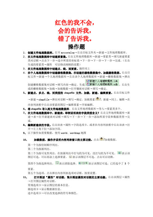
红色的我不会,会的告诉我,错了告诉我。
操作题1、创建文件地理数据库。
打开arccatalog→右击目标文件夹→新建→文件地理数据库。
2、在文件地理数据库中创建要素集。
右击文件地理数据库→新建→要素类→填写新建要素类对话框→点击下一步→选中所需的坐标系→下一步→下一步→下一步→完成。
(右击生成的要素类→属性可以修改刚刚的设置)3、在文件地理数据库中创建点、线、面要素。
操作同上4、在个人地理数据库中创建栅格数据集,在创建的栅格数据集中,加载栅格数据。
右击目标文件→新建→个人地理数据库→右击该个人地理数据库→新建→栅格数据集→弹出创建栅格数据集对话框→填写内容→确定。
生成。
右击生成的栅格数据集→加载→加载数据→打开镶嵌对话框→填写→确定。
5、新建点,多点,线,面类型的shapefile文件,加载,新建、编辑要素。
右击目标文件→新建→shapfile→弹出对话框→填写→确定。
加载要素。
新建→同上。
编辑→在内容列表框中右击该要素的图层→编辑要素→开始编辑。
6、将shapefile导入到文件地理数据库。
右击文件地理数据库→导入→要素类多个。
7、在文件地理数据库中,新建表:举例说明表的字段类型含义?右击文件地理数据库→新建→表→打开新建表对话框→填写→下一步→下一步→添加所需字段和数据类型→完成。
8、编辑新建表的字段。
右击该表→属性→字段选项卡。
或者在内容列表框中右击该表→打开→左上角下拉→添加字段。
9、以下操作如需要数据,使用world、worldcap地图10、加载数据,操作并说明内容列表窗口的主要功能。
点击加载数据。
第一个为按绘制顺序列出。
第二个为按源列出。
第三个为按可见性列出。
在按源列出中打勾的为可见,没打勾的为不可见。
表示该图层可选,可以再涂上选择要素。
表示该图层不可选。
点击可以切换。
第四个为按选择列出。
表示清除选择。
表示该图层可选,已经选中了5个要素。
第五个为选项。
点击弹出内容列表选项对话框。
按需设置。
GIS操作手册
GIS学习笔记生标准框主菜单:投影变换(绘制经纬网)给横向网间隔()km(一般1或5)纵向网间隔()km依图经纬网格来定1、①最小起始经度(输入左下角经度数值)②最大结束经度(右上角经度数值)③最小起始纬度(左下角纬度数值)④最大结束纬度(右上角纬度数值)⑤经度间隔,纬度间隔给值:5000(起始网经度、纬度给10)2、点击角度单位:坐标系类型(选择,下拉表)选地理坐标坐标单位(选择)DDDMMSS.SS(度分秒)椭球参数(选择)北京坐标系,确定,确定,(或西安坐标系)点击投影参数:坐标系类型(选择)(投影平面直角)比例尺分母(给值)例图为10000,按图上比例尺给值椭球参数(选择)北京坐标系,确定,确定,(或西安坐标系)点击点参数:点击投影带类型:这里选(3°带)点击投影序号(给值,得查)这里为42°给高度3、宽度3。
6°=22 3°=423、显示1:1,选点、线确定,点保存(存名为标准框),点保存(关闭)。
在主菜单中:①装入要改图的点、线、面。
②输入四角坐标(子图号406,红色,给图层号)。
③关所有层,改层开关,打开图层(上步存的)④存出四点红“十”字点(实际值)主菜单中:输入编辑中,打开标准框,对对经纬度点内框四角坐标(子图号406,兰色)(给图层号)单存出四点(用部分存点)名为理论值。
关所有层,改层开关,(存名)(理论值)4、实用服务中①点误差校正,(打开实际值、理论值)②实际值用(红“十”光标点)S——实际值,E——实际(确定),1:1实际确定,F自动采集控制点(1、2、3、4)。
③控制点(理论值)(以上①②)(添加控制点)用手动控制点(存名控制点)关闭要校正的图(文件—保存控制点),打开文件,打开控制点。
④数据校正(保存点线区)另存文件(带NEW的P、L、T)存入输入编辑中,打开标准图框,添加点线区文件输入编辑中,打开标准图框(改后的)⑤文件(打开标准图框)删除标准图框。
GISoffice使用说明

良好的扩展性,可与其他专业软件进行集 成。
版本更新及特点
最新版本:GISoffice X.X(具
体版本号根据软件更新情况而
定)。
01
更新特点
02
增强了数据处理性能,提高了处
理速度。
03
新增了多种空间分析算法,提高
了分析精度。
04
优化了用户界面,提升了用户体 验。
05
加强了与其他软件的兼容性,便
于数据共享和交换。
数据导入/导出方法
数据导入
通过“文件”菜单中的“导入”选项, 选择相应的数据格式进行导入。导入 过程中可设置坐标系、编码等参数。
数据导出
选择需要导出的图层或数据,通过 “文件”菜单中的“导出”选项,选 择相应的数据格式进行导出。导出时 可设置输出范围、分辨率等参数。
数据编辑技巧
选择工具
使用选择工具可以快速选择需要 编辑的要素,支持点选、框选、
多边形选择等多种方式。
编辑工具
提供添加、删除、修改等编辑工 具,支持对点、线、面等要素进 行编辑。
属性编辑
在属性表中可以直接修改要素的 属性信息,如名称、类型、值等。
批量处理
支持对多个要素进行批量处理, 如批量修改属性、批量移动等,
提高编辑效率。
05
空间分析功能应用
缓冲区分析
创建缓冲区
01
根据指定的距离或时间阈值,在点、线、面等地理要素周围创
材质与贴图
为三维对象添加合适的材质和贴图, 提高场景的真实感和可视化效果。
光影与渲染
调整光影参数,实现场景的光照效果; 利用渲染技术,提升三维场景的整体 视觉效果。
07
输出与共享成果
打印输出设置
GIS产品用户操作手册COMM1216V12 ——GIS产品操作手册资料文档
GIS产品用户操作手册20××年12月文档修改记录目录1GIS产品介绍(老朱负责) (1)1.1产品功能介绍(SAP客户端涵盖在产品功能范围之列) (1)1.2产品运行环境要求(需J AVA提供浏览器等配套运行环境的要求,区分SAP&J AVA) (1)1.3产品登陆方式(SAP客户端登陆方式也需要介绍) (1)1.4个人资料修改方式 (1)2工程管理模块操作说明(小刀负责、洪飞配合) (1)2.1工程管理模块功能介绍 (1)2.2XX功能介绍操作说明(针对二级明细功能) (2)2.2.1功能说明 (2)2.2.2功能进入方式(文字+截图) (2)2.2.3界面重要字段说明 (2)2.2.4详细操作步骤(文字+配套截图) (3)2.2.5注意事项 (3)3成本合约管理模块操作说明(老朱负责、娜娜配合) (4)4销售管理模块操作说明(大龙负责) (110)5财务管理模块操作说明(小马负责、培平配合) (110)6操作手册编写要求 (110)1GIS产品介绍(老朱负责,参考白皮书)对GIS产品的适用范围及功能模块进行介绍。
1.1 产品功能介绍(SAP客户端涵盖在产品功能范围之列)列表对GIS产品的各功能模块进行介绍。
(模块-一级功能)1.2 产品运行环境要求(需Java提供浏览器等配套运行环境的要求,区分SAP&Java)对GIS产品运行的浏览器进行介绍。
1.3 产品登陆方式(SAP客户端登陆方式也需要介绍)对GIS产品登陆方式进行介绍。
1.4 个人资料修改方式对GIS产品如何修改个人密码等信息等功能进行介绍。
2工程管理模块操作说明(小刀负责、洪飞配合)2.1 工程管理模块功能介绍用一段话对工程管理模块的功能进行整体介绍,并用下列表格对功能进行列举。
(一级功能-二级明细功能)项目资源管理项目档案维护项目资源管理项目结构维护项目资源管理面积及指标维护项目资源管理证照及成果维护……表 2-1-1 工程管理模块功能2.2 XX功能介绍操作说明(针对二级明细功能)2.2.1功能说明对功能及其作用进行简单的定义说明。
Trimble_Geomatics_Office的使用方法(第2版)[1]
![Trimble_Geomatics_Office的使用方法(第2版)[1]](https://img.taocdn.com/s3/m/2f3bc3da7f1922791688e821.png)
○CAD/ASCII(导入格式)标签 使用 CAD/ASCII 标签导入下列格式:
○自定义(导入格式)标签 使用自定义标签: ·用自定义格式导入数据文件。 ·添加新的自定义导入格式。 ·编辑已有的自定义导入格式。 ·删除自定义导入格式。 有以下几种自定义格式: ·定界点 ·宽度固定点 ·名称,横坐标,纵坐标,高程,代码 ·名称,纬度,经度,高度,代码(地方) ·名称,纬度,经度,高度,代码 (WGS-84) ·名称,纵坐标,横坐标,高程,代码
○单位和格式标签 坐标 设置坐标值的显示单位(北方向和东方向)。选项是国际的英尺,令,米,或美国测量英 尺。 高程/高度 设置高程显示单位。选项是国际的英尺,令,米,或美国测量英尺。 坐标的小数位 设置显示坐标的小数位个数。能指定直到小数点后的五位数。
坐标顺序
设置坐标顺序。选项是北向第一或东向第一。
2.新项目对话框
·选择文件 / 新项目。
·在标准工具栏上单击新项目钮。 ·按 Ctrl+N。 ·在项目条上单击快捷的新项目。 如图 02: 名称 输入您想创建的项目名称。用文件夹钮选择时,带有项目名称的新文件夹就在当前的 项目文件夹下创建出来。 模板 板列表显示了系统中可以用的项目模板。
图 02 细节 细节列表显示了坐标系统的细节和所选模板的标题。 新建 单击新建来创建一个新项目或新模板。
2.导入GPS(*.dat)数据文件
按照以上相同的步骤,导入以下的 GPS 数据(*.dat)文件: fast0550.dat Ktom0550.dat Moon0550.dat Wave0550.dat 如图 10:
水准面模型的测量精度,选择测量选项。重新计算使用此质量来决定高程的质量(对于 GPS 点)或从大地水准面模型得出的高度(对于地面点)。如果没有用于项目坐标系统的大地水准 面,此域无效。
GIS 500 Professional 说明书

2 |English...................................................Page5Español................................................Página23Português do Brasil.....................................Página37中文.......................................................页48繁體中文..................................................頁59한국어...............................................페이지68ไทย......................................................หน้า78Bahasa Indonesia.....................................Halaman91Tiếng Việt...............................................Trang1021 609 92A 5H0 | (16.12.2019)Bosch Power Tools| 3Bosch Power Tools1 609 92A 5H0 | (16.12.2019)4 |°C(h)(i)(e)(d)(f)(g)1 609 92A 5H0 | (16.12.2019)Bosch Power ToolsEnglish | 5 EnglishSafety instructionsAll instructions must be read and observed in order for the meas-uring tool to function safely. The safeguards integrated into themeasuring tool may be compromised if the measuring tool is notused in accordance with these instructions. Never make warningsigns on the measuring tool unrecognisable. SAVE THESE IN-STRUCTIONS FOR FUTURE REFERENCE AND INCLUDE THEM WITH THE MEASUR-ING TOOL WHEN TRANSFERRING IT TO A THIRD PARTY.u Warning! If operating or adjustment devices other than those specified here are used or other procedures are carried out, this can lead to dangerous exposure to radiation.u The measuring tool is delivered with a warning label (marked in the illustrationof the measuring tool on the graphics page).uyour head away from the beam.u Do not make any modifications to the laser equipment.u Do not use the laser goggles as protective goggles. The laser goggles make the laser beam easier to see; they do not protect you against laser radiation.u Do not use the laser goggles as sunglasses or while driving. The laser goggles do not provide full UV protection and impair your ability to see colours.Bosch Power Tools 1 609 92A 5H0 | (16.12.2019)6 | Englishu Have the measuring tool serviced only by a qualified specialist using only ori-ginal replacement parts. This will ensure that the safety of the measuring tool is maintained.u Do not let children use the laser measuring tool unsupervised. They could acci-dentally dazzle someone.u Do not use the measuring tool in explosive atmospheres which contain flam-mable liquids, gases or dust. Sparks may be produced inside the measuring tool, which can ignite dust or fumes.u The measuring tool may not be 100% accurate for technological reasons. Envir-onmental factors (e.g. dust or steam in the area being measured), temperature fluctu-ations (e.g. from fan heater) as well as the nature and condition of the surfaces being measured (e.g. highly reflective or transparent materials) can distort measurement readings.u Protect the measuring tool, particularly the area around the infrared lens and laser, from moisture and snow. The reception lens could fog up and distort the measurements. Incorrect settings on the tool and other atmospheric influences maymake the measurements inaccurate. Otherwise, object temperatures could be shown to be hotter or colder than they are, which may present a danger if touched.u Temperature measurements will only be correct if the emissivity setting matches the emissivity of the object. Otherwise, object temperatures could be shown to be hotter or colder than they are, which may present a danger if touched.u Take the batteries out of the measuring tool when it is being stored or transpor-ted. Persons are at risk of being blinded if the on/off switch is unintentionally pressed.Product Description and SpecificationsPlease observe the illustrations at the beginning of this operating manual.Intended UseThe measuring tool is intended for contactless measurement of surface temperature. The measuring tool must not be used for temperature measurement on persons and an-imals or for other medical purposes.The measuring tool is not suitable for surface temperature measurement of gases or li-quids.The measuring tool is not intended for temperature measurement of food.The measuring tool is suitable for indoor use.1 609 92A 5H0 | (16.12.2019)Bosch Power ToolsEnglish | 7Product FeaturesThe numbering of the product features shown refers to the illustration of the measuring tool on the graphic page.Display elementsTechnical dataBosch Power Tools 1 609 92A 5H0 | (16.12.2019)8 | English1 609 92A 5H0 | (16.12.2019)Bosch Power ToolsEnglish | 9At an ambient temperature T of between –5 °C and 21 °C the measuring accuracy varies by±0.1×|T–21| °C for surface temperatures below 100 °C and±0.1×|T–21| % for surface temperatures above 100 °C.At an ambient temperature T of between 25 °C and 50 °C the measuring accuracy varies by±0.1×|T–25| °C for surface temperatures below 100 °C and±0.1×|T–25| % for surface temperatures above 100 °C.B)At a measuring distance of 0.1–0.3 m from the surfaceC)At a measuring distance of 0.75–1.25 m from the surfaceD)Refers to infrared measurement, see figure:E)Values in accordance with the Association of German Engineers' VDI/VDE 3511 part 4.3 stand-ard (publication date July 2005); applies for 90 % of the measuring signal.In all areas beyond the values detailed in the technical data, deviations are possible in measure-ment readings.F)Only non-conductive deposits occur, whereby occasional temporary conductivity caused bycondensation is expected.AssemblyInserting/changing the batteriesIt is recommended that you use alkaline manganese batteries to operate the measuring tool.To open the battery compartment cover (4), press the locking mechanism (5) and lift open the battery compartment cover. Insert the batteries. When inserting the batteries, ensure the polarity is correct according to the representation on the inside of the battery compartment cover.The battery indicator (a) shows the batteries' state of charge:Bosch Power Tools 1 609 92A 5H0 | (16.12.2019)10 | Englishreplaced.Always replace all the batteries at the same time. Only use batteries from the same man-ufacturer and which have the same capacity.u Take the batteries out of the measuring tool when you are not using it for a pro-longed period of time. The batteries can corrode and self-discharge during pro-longed storage.OperationStarting Operationu Protect the measuring tool from moisture and direct sunlight.u Do not expose the measuring tool to any extreme temperatures or variations in temperature. For example, do not leave it in a car for extended periods of time. In case of large variations in temperature, allow the measuring tool to adjust to the ambi-ent temperature before putting it into operation. The precision of the measuring tool may be compromised if exposed to extreme temperatures or variations in temperat-ure.u Make sure that the measuring tool is correctly acclimatised. In case of large vari-ations in temperature, acclimatisation can take up to 30 minutes. This may be the case, for example, if you first perform a measurement in the cool cellar and then go up to the warm attic.u Avoid hard knocks to the measuring tool or dropping it. After severe external influ-ences and in the event of abnormalities in the functionality, you should have the measuring tool checked by an authorised Bosch after-sales service agent.u Do not close or cover the reception lens (2) or the laser outlet aperture (1).1 609 92A 5H0 | (16.12.2019)Bosch Power ToolsEnglish | 11Switching on/offThe following options are available for switching on the measuring tool:–Switch on the measuring tool using the on/off button (9). The measuring tool will be ready to use again following a brief start-up sequence. No measurement is initiated at this stage and the laser is still switched off.–Switch on the measuring tool using the measuring button (3). After briefly pressing the measuring button (3), the measuring tool will be ready to take measurements following a brief start-up sequence. If you press and hold the measuring button (3) for more than three seconds, the laser will be switched on after the start-up sequence and the measuring tool will immediately begin measuring.u Never leave the measuring tool unattended when switched on, and ensure the measuring tool is switched off after use. Others may be dazzled by the laser beam. u Do not direct the laser beam at persons or animals and do not stare into the laser beam yourself (even from a distance).To switch off the measuring tool, press the on/off button (9).If no button on the measuring tool is pressed for approx. 1 minutes, the measuring tool will automatically switch off to preserve battery life.Measurement preparationsAdjusting the emissivityTo determine the surface temperature, the tool performs a contactless measurement of the natural infrared thermal radiation emitted by the object at which the tool is aimed. For optimum measuring results, the emissivity setting (see "Emissivity", page 14) on the measuring tool must be checked before every measurement and adapted to the ob-ject being measured if necessary.When the measuring tool is switched on for the first time, the high emissivity setting is activated by default. If the emissivity is changed, all the measured values will be erased. The emissivity setting remains saved when the measuring tool is switched off.You can select from three different emissivity settings on the measuring tool. The follow-ing overview shows commonly used materials of a similar emissivity for each emissivity setting; note that these are examples and not an exhaustive list. Because the emissivity of a material is dependent on a variety of factors and is therefore variable, the details in the following overview serve only as guide values.Bosch Power Tools 1 609 92A 5H0 | (16.12.2019)12 | EnglishThe following emissivity gradings are used:–High emissivity grading: Approx. 0.95–Medium emissivity grading: Approx. 0.85–Low emissivity grading: Approx. 0.75To change the emissivity setting, press the button Mode (8) repeatedly until the emissiv-ity indicator (c) shows the required emissivity for the next measurement.u Temperature measurements will only be correct if the emissivity setting matches the emissivity of the object. Otherwise, object temperatures could be shown to be hotter or colder than they are, which may present a danger if touched. Measuring surfaceThe infrared radiation of the measuring surface is determined during the contactless measurement of the surface temperature.The laser point marks the approximate centre of the measuring surface. For an optimum measurement reading, position the measuring tool so that the laser beam meets the measuring surface perpendicularly to this point.u Do not direct the laser beam at persons or animals and do not stare into the laser beam yourself (even from a distance).Increasing the distance between the measuring tool and the object being measured in-creases the size of the measuring surface. At a distance of 1 m, the measuring surface is approx. 8.3 cm in size if the laser beam is perpendicular to a flat measuring surface.1 609 92A 5H0 | (16.12.2019)Bosch Power ToolsEnglish | 13 At a surface temperature of −10 °C to +500 °C, the optimum measuring distance is between 0.75 m and 1.25 m. Below −10 °C, the optimum measuring distance is between 10 cm and 30 cm.The displayed reading is the average value of all temperatures measured within the measuring surface.u Stand back from very hot objects. There is a risk of burns.u Do not hold the measuring tool directly against hot surfaces. The heat can damage the measuring tool.Information about the measuring conditionsHighly reflective or glossy surfaces (e.g. glossy tiles, stainless steel fronts or cooking pots) can affect the surface temperature measurement. If necessary, mask the area to be measured with a dark, matt adhesive tape that conducts heat well. Allow the tape to ac-climatise briefly on the surface.Measuring through transparent materials (e.g. glass or transparent plastics) is funda-mentally not possible.Consequently, the more suitable and stable the measuring conditions are, the more ac-curate and reliable the measurement readings are.Infrared temperature measurement is impaired by smoke, steam or dusty air.It is therefore important to ventilate the room prior to measuring, especially when the air is contaminated or steamy. For example, do not perform measurements in a bathroom immediately after the shower has been used.Once ventilated, allow the room to reacclimatise a while until it returns to the usual tem-perature.Measuring functionsIndividual measurementsBriefly pressing the measuring button (3) once switches the laser on and actuates a single measurement.The measuring process can take up to half a second and is indicated by the SCAN (h) in-dicator lighting up. Once the measurement has been completed, the laser switches off automatically, the indicator SCAN disappears and both the most recent measurement reading and the reading before it are shown on the display.Continuous measurementFor continuous measurements, press and hold the measuring button (3). The laser re-mains switched on and the indicator SCAN appears in the display. Using slow move-ments, aim the laser at each of the surfaces to be measured, one by one.Bosch Power Tools 1 609 92A 5H0 | (16.12.2019)14 | EnglishThe indicator on the display is continually updated. As soon as you let go of the measur-ing button (3), the measurement is stopped, the indicator SCAN disappears and the laser is switched off.The most recent measurement reading and the reading before it are shown on the dis-play.Errors – causes and corrective measuresMeasuring tool not acclimatisedThe measuring tool has been subjected to extreme fluctuations in temperature and did not have sufficient time to adjust.Ambient temperature outside the operating temperature rangeThe ambient temperature is too high or too low for the measuring tool to operate. Surface temperature outside the measuring rangeThe indicator flashes if the surface temperature of the object being measured in the measuring area is too high (above 500 °C, see indicator (g)) or too low (below −30 °C,see indicator (f)). The temperature of this object cannot be measured. Aim the laser at another object and start a new measurement.Internal errorIf the measuring tool has an internal fault, Err is shown on the display and the (i) sym-bol flashes. To reset the software, remove the batteries, wait a few seconds and then re-insert the batteries.If the error persists, have the measuring tool checked by a Bosch customer service agent. Do not open the measuring tool yourself.Glossary of termsEmissivityThe emissivity of an object depends on the material and the structure of its surface. It in-dicates whether a particular object emits a high or low level of infrared thermal radiation (in comparison to other objects of the same temperature).1 609 92A 5H0 | (16.12.2019)Bosch Power ToolsEnglish | 15 Maintenance and ServiceMaintenance and Cleaningu Check the measuring tool before each use. If the measuring tool is visibly damaged or parts have become loose inside the measuring tool, safe function can no longer be ensured.Only store and transport the measuring tool in a suitable container, such as the original packaging. Do not affix any stickers near to the sensor on the measuring tool.Always keep the measuring tool clean and dry to ensure optimum, safe operation. Never immerse the measuring tool in water or other liquids.Wipe off any dirt using a dry, soft cloth. Do not use any detergents or solvents.When cleaning the measuring tool, ensure that no liquids enter the tool.Clean the reception lens (2) and laser outlet aperture (1) very carefully:Ensure that there is no lint on the reception lens or the laser outlet aperture. Do not at-tempt to remove dirt from the reception lens using pointed objects, and do not wipe overthe reception lens (risk of scratching). If necessary, you can carefully blow away dirt us-ing oil-free compressed air.If repairs are required, send in the measuring tool in its original packaging.After-Sales Service and Application ServiceOur after-sales service responds to your questions concerning maintenance and repair of your product as well as spare parts. You can find explosion drawings and information on spare parts at: The Bosch product use advice team will be happy to help you with any questions about our products and their accessories.In all correspondence and spare parts orders, please always include the 10‑digit article number given on the nameplate of the product.CambodiaRobert Bosch (Cambodia) Co., LtdUnit 8BC, GT Tower, 08th Floor, Street 169,Czechoslovakia Blvd, Sangkat Veal VongKhan 7 Makara, Phnom PenhVAT TIN: 100 169 511Tel.: +855 23 900 685Tel.: +855 23 900 660.khBosch Power Tools 1 609 92A 5H0 | (16.12.2019)16 | EnglishPeople’s Republic of ChinaChina MainlandBosch Power Tool (China) Co. Ltd.Bosch Service Center567, Bin Kang RoadBin Kang DistrictHangzhou, Zhejiang ProvinceChina 310052Tel.: (0571) 8887 5566 / 5588Fax: (0571) 8887 6688 x 5566# / 5588#E-Mail:***************.comHK and Macau Special Administrative RegionsRobert Bosch Co. Ltd.21st Floor, 625 King’s RoadNorth Point, Hong KongCustomer Service Hotline: +852 2101 0235Fax: +852 2590 9762E-Mail:*************.comIndiaBosch Service Center69, Habibullah Road, (Next to PSBB School), T. NagarChennai–600077Phone: (044) 64561816Bosch Service Center18, Community CenterPhase 1, MayapuriNew Delhi–110064Phone: (011) 43166190IndonesiaPT Robert BoschPalma Tower 10th FloorJalan RA Kartini II-S Kaveling 6Pondok Pinang, Kebayoran LamaJakarta Selatan 12310Tel.: (21) 3005-5800www.bosch-pt.co.id1 609 92A 5H0 | (16.12.2019)Bosch Power ToolsEnglish | 17 MalaysiaRobert Bosch Sdn. Bhd.(220975-V) PT/SMYNo. 8A, Jalan 13/646200 Petaling JayaSelangorTel.: (03) 79663194Toll-Free: 1800 880188Fax: (03) 79583838E-Mail:**********************.com.myPakistanRobert Bosch Middle East FZE – Pakistan Liaison Office2nd Floor Plaza # 10, CCA Block, DHA Phase 5Lahore, 54810Phone: +92(303)4444311Email:*********************PhilippinesRobert Bosch, Inc.28th Floor Fort Legend Towers,3rd Avenue corner 31st Street,Fort Bonifacio, Global City,1634 Taguig CityTel.: (632) 8703871Fax: (632) 8703870.phSingaporePowerwell Service Centre Ptd LtdBosch Authorised Service Centre (Power Tools)4012 Ang Mo Kio Ave 10, #01-02 TECHplaceSingapore 569628Tel.: 6452 1770Fax: 6452 1760E-Mail:*******************.sgThailandRobert Bosch Ltd.FYI Center Tower 1, 5th Floor,Bosch Power Tools 1 609 92A 5H0 | (16.12.2019)18 | English2525 Rama IV Road, Klongtoei,Bangkok 10110Tel.: 02 0128888Fax: 02 0645802www.bosch.co.thBosch Service – Training CentreLa Salle Tower Ground Floor Unit No.210/11 La Salle Moo 16Srinakharin RoadBangkaew, Bang PleeSamutprakarn 10540Tel.: 02 7587555Fax: 02 7587525VietnamBranch of Bosch Vietnam Co., Ltd in HCMC14th floor, Deutsches Haus, 33 Le DuanBen Nghe Ward, District 1, Ho Chi Minh CityTel.: (028) 6258 3690Fax: (028) 6258 3692 - 6258 3694Hotline: (028) 6250 8555Email:**************************.com.vnBahrainEA Juffali and Brothers for Technical Equipment Company.Kingdom of Bahrain, Al Aker - Block 0624 - Road 2403 - Building 0055DPhone: +97317704537Fax: +973177045257Email:*****************.saEgyptRBEG-LLC22 Kamal Eldin HusseinSheraton Heliopolis11799 CairoE-mail:******************************.comIranRobert Bosch Iran3rd Floor, No 3, Maadiran BuildingAftab St., Khodami St., Vanak Sq.1 609 92A 5H0 | (16.12.2019)Bosch Power ToolsEnglish | 19 Tehran 1994834571Phone: +9821- 86092057IraqSahba Technology GroupAl Muthana airport roadBaghdadPhone Bagdad: +964 (0) 7 901 930366Phone Dubai: +971 (0) 4 422 1898Email:**************************JordanRoots Arabia – JordanAl-Hurriyah Street, Al-MuqabaleinAmman 11623, JordanP.O. Box: 110068Tel. : +962 6 4398990E-mail:*********************KuwaitShuwaikh Industrial Area, Block 1, Plot 16, Street 3rdP.O. Box 164 – Safat 13002Phone: +965 - 2496 88 88Fax: +965 - 2481 08 79E-mail:***********************LebanonTehini Hana & Co. S.A.R.L.P.O. Box 90-449Jdeideh 1202 2040Dora-BeirutPhone: +9611255211Email:**************************LibyaEl Naser for Workshop ToolsSwanee Road, Alfalah AreaTripoliPhone: +218 21 4811184OmanMalatan Trading & Contracting LLCP.O. Box 131, Ruwi, MuscatBosch Power Tools 1 609 92A 5H0 | (16.12.2019)20 | EnglishPostal Code: 112, Sultanate of OmanPhone: +968 2479 4035/4089/4901Mob: +968-91315465Fax: +968 2479 4058E-Mail:***********************QatarInternational Construction Solutions W L LP. O. Box 51, DohaPhone: +974 40065458Fax: +974 4453 8585Email:***************Saudi ArabiaJuffali Technical Equipment Co. (JTECO)P.O.Box: 1049 – Jeddah 21431 – KSAJeddah: 00966 (0) 12 692 0770 – Ext 433Riyadh: 00966 (0) 11 409 3976 – Ext-30/34/39Dammam: 00966 (0) 13 833 9565E-mail:****************.saSyriaDallal Establishment for Power ToolsDamascus. Baramkeh street - Ibn Amer street,Phone: +963112241006 or 009631122414009Mobile: 00963991141005Email:***********************United Arab EmiratesCentral Motors & Equipment,P.O. Box 26255, DubaiDubai: 00971 (0) 4 3090920/3090930Abu Dhabi: 00971 (0) 2 4017745Sharjah: 00971 (0) 6 5932777Al Ain: 00971 (0) 3 7157419E-Mail:********************************YemenAbu Alrejal Trading CorporationP.O. Box : 17024 , Zubeiry St.Sana'a, YemenTel: +967-1-20 20 101 609 92A 5H0 | (16.12.2019)Bosch Power ToolsEnglish | 21 Fax: +967-1-47 19 17E-mail:*************************/********************EthiopiaForever plcKebele 2,754, BP 4806,Addis AbabaPhone: +251 111 560 600Email:**********************GhanaRobert Bosch Ghana Limited21 Kofi Annan Road Airport Residential Area AccraTel. +233 (0)3027 94616KenyaRobert Bosch East Africa LtdMpaka Road P.O. Box 85600606 NairobiNigeriaRobert Bosch Nigeria Ltd.52–54 Isaac John Street P.O. BoxGRA Ikeja – LagosTanzaniaDiesel & Autoelectric Service Ltd.117 Nyerere Rd., P.O. Box 70839Vingunguti 12109, Dar Es SalaamPhone: +255 222 861 793/794Australia, New Zealand and Pacific IslandsRobert Bosch Australia Pty. Ltd.Power ToolsLocked Bag 66Clayton South VIC 3169Customer Contact CenterInside Australia:Phone: (01300) 307044Fax: (01300) 307045Inside New Zealand:Phone: (0800) 543353Fax: (0800) 428570Bosch Power Tools 1 609 92A 5H0 | (16.12.2019)22 | EnglishOutside AU and NZ:Phone: +61 3 95415555.auRepublic of South AfricaCustomer serviceHotline: (011) 6519600Gauteng – BSC Service Centre35 Roper Street, New CentreJohannesburgTel.: (011) 4939375Fax: (011) 4930126E-Mail:****************.zaKZN – BSC Service CentreUnit E, Almar Centre143 Crompton StreetPinetownTel.: (031) 7012120Fax: (031) 7012446E-Mail:****************.comWestern Cape – BSC Service CentreDemocracy Way, Prosperity ParkMilnertonTel.: (021) 5512577Fax: (021) 5513223E-Mail:**********.zaBosch HeadquartersMidrand, GautengTel.: (011) 6519600Fax: (011) 6519880E-Mail:********************.comArmenia, Azerbaijan, GeorgiaRobert Bosch Ltd.David Agmashenebeli ave. 610102 Tbilisi, GeorgiaTel. +9953225100731 609 92A 5H0 | (16.12.2019)Bosch Power ToolsEspañol | 23 Kyrgyzstan, Mongolia, Tajikistan, Turkmenistan, UzbekistanTOO “Robert Bosch” Power Tools, After Sales ServiceMuratbaev Ave., 180050012, Almaty, KazakhstanServiceEmail:***********************Official Website: , IsraelLedico Ltd.31 Lazrov StreetP.O. Box 6018 Rishon Le Ziyon******************DisposalMeasuring tools, accessories and packaging should be recycled in an environmentallyEspañolIndicaciones de seguridadLeer y observar todas las instrucciones, para trabajar sin peligroy riesgo con el aparato de medición. Si el aparato de medición nose utiliza según las presentes instrucciones, pueden menoscabar-se las medidas de seguridad integradas en el aparato de medi-ción. Jamás desvirtúe las señales de advertencia del aparato de medición. GUARDE BIEN ESTAS INSTRUCCIONES Y ADJUNTELAS EN LA ENTREGA DEL APARATO DE MEDICIÓN.u Precaución – si se utilizan dispositivos de manejo o de ajuste distintos a los espe-cificados en este documento o si se siguen otros procedimientos, esto puede conducir a una peligrosa exposición a la radiación.u El aparato de medición se entrega con un rótulo de advertencia (marcado en la representación del aparato de medición en la página ilustrada con el número). Bosch Power Tools 1 609 92A 5H0 | (16.12.2019)24 | Españolbralo con la etiqueta adhesiva adjunta en su idioma del país antes de la primerauver inmediatamente la cabeza fuera del rayo.u No efectúe modificaciones en el equipamiento del láser.u No utilice las gafas de visualización láser como gafas protectoras. Las gafas de vi-sualización láser sirven para detectar mejor el rayo láser; sin embargo, éstas no prote-gen contra la radiación láser.u No utilice las gafas de visualización láser como gafas de sol o en el tráfico. Las ga-fas de visualización láser no proporcionan protección UV completa y reducen la per-cepción del color.u Sólo deje reparar el aparato de medición por personal técnico calificado y sólo con repuestos originales. Solamente así se mantiene la seguridad del aparato de medición.u No deje que niños utilicen el aparato de medición láser sin vigilancia. Podrían deslumbrar involuntariamente personas.u No trabaje con el aparato de medición en un entorno potencialmente explosivo, en el que se encuentran líquidos, gases o polvos inflamables. El aparato de medi-ción puede producir chispas e inflamar los materiales en polvo o vapores.u Debido a motivos tecnológicos, la herramienta de medición no puede garantizar una seguridad absoluta. Las influencias del medio ambiente (p. ej. polvo o vapor en el margen de medición), las fluctuaciones de temperatura (p. ej. por termoventilador) así como naturaleza y estado de las superficies de medición (p. ej. materiales alta-mente reflectantes o transparentes) pueden falsear los resultados de la medición.u Proteja el aparato de medición, especialmente el área del lente infrarrojo y el lá-ser, ante la humedad y la nieve. El lente receptor podría empañarse y falsear los resultados de medición. Los ajustes incorrectos del aparato así como otros factores1 609 92A 5H0 | (16.12.2019)Bosch Power Tools。
ESRI ArcGIS Pro 3.1 用户指南说明书
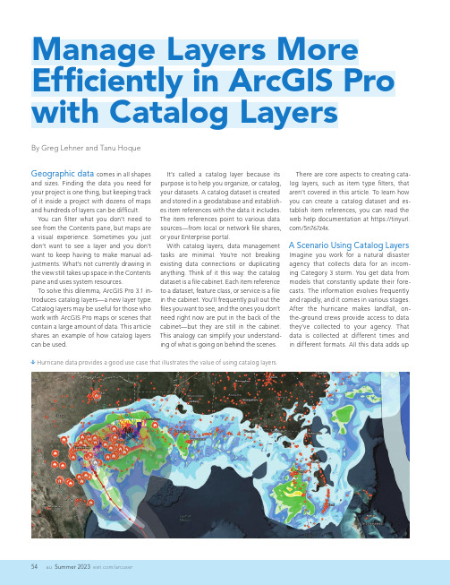
Summer 2023 /arcuserGeographic data comes in all shapesand sizes. Finding the data you need for your project is one thing, but keeping track of it inside a project with dozens of maps and hundreds of layers can be difficult.You can filter what you don’t need to see from the Contents pane, but maps are a visual experience. Sometimes you just don’t want to see a layer and you don’t want to keep having to make manual ad-justments. What’s not currently drawing in the view still takes up space in the Contents pane and uses system resources.To solve this dilemma, ArcGIS Pro 3.1 in-troduces catalog layers—a new layer type. Catalog layers may be useful for those who work with ArcGIS Pro maps or scenes that contain a large amount of data. This article shares an example of how catalog layers can be used.By Greg Lehner and Tanu HoqueIt’s called a catalog layer because its purpose is to help you organize, or catalog, your datasets. A catalog dataset is created and stored in a geodatabase and establish-es item references with the data it includes. The item references point to various data sources—from local or network file shares, or your Enterprise portal.With catalog layers, data management tasks are minimal. You’re not breaking existing data connections or duplicating anything. Think of it this way: the catalog dataset is a file cabinet. Each item reference to a dataset, feature class, or service is a file in the cabinet. You’ll frequently pull out the files you want to see, and the ones you don’t need right now are put in the back of the cabinet—but they are still in the cabinet. This analogy can simplify your understand-ing of what is going on behind the scenes.â Hurricane data provides a good use case that illustrates the value of using catalog layers.There are core aspects to creating cata-log layers, such as item type filters, that aren’t covered in this article. To learn how you can create a catalog dataset and es-tablish item references, you can read the web help documentation at https:///5n767z4x.A Scenario Using Catalog LayersImagine you work for a natural disaster agency that collects data for an incom-ing Category 3 storm. You get data from models that constantly update their fore-casts. The information evolves frequently and rapidly, and it comes in various stages. After the hurricane makes landfall, on-the-ground crews provide access to data they’ve collected to your agency. That data is collected at different times and in different formats. All this data adds upManage Layers More Efficiently in ArcGIS Pro with Catalog LayersSummer 2023auHands Onquickly. Every piece of data is important, but consuming all this data is a different story. Everyone involved in collecting, ed-iting, and uploading the data has done their work, but now you must make some-thing from it.The file cabinet is overflowing—but you can manage it. In any map with a catalog layer, one of the two sublayers you will see is a Footprints layer. When the catalog dataset is created, it builds convex hull polygons of each item’s footprint and puts them into one feature layer. The footprints show the spatial extent of every item (like the footprints in a mosaic dataset). Any given layer’s spatial extent isn’t immedi-ately clear when looking at a geodatabase or a service layer in a file directory.If you right-click the catalog layer in the Contents pane and open its attribute table, you will see that each item is a record in the table. The Item Source field stores the path of the item. Meanwhile, the Item Type field tells you what kind of data it is. It’s like áá The Footprints layer shows the extent of each sublayer.á When viewing the catalog layer’s attribute table, you will see that each item is a record in the table. The Item Source field stores the pathof the item. The Item Type field tells you what kind of data it is.the files in your file cabinet tell you what’s inside without needing to open them. The other fields you see are detailed in the help documentation. You can also add fields. The second layer in the catalog layer’s structure is named Layers In View. It is a composite sublayer that does exactly what the name implies. Catalog layers dynamically load layers in your map based on spatial, tem-poral, or range filters. If an item in your cata-log layer is in view, it is listed in the Contents pane under the Layers In View heading.Summer 2023/arcuserItems in the catalog layer appear in the Contents pane as you pan around the map. But which layers get drawn? That’s where the Feature Order Weight field in the cata-log layer attribute table comes into play. Feature drawing order was introduced with the release of ArcGIS Pro 3.1. Catalog layers are included as one of the default fields. You can edit which items are drawn on top by giving them a larger value—like keeping your most important files toward the front of the file cabinet.There are other ways to limit what gets drawn as well. You can modify the layer limit, or you can also set scale ranges for each item in your dataset. These settings will be reflected in your map as you change scales. Lastly, the contents of a catalog dataset include feature classes, BIM files, and LAS datasets. Because each of these items are references to the data—not the actual items—there are limitations with what you can do with them. In almost all cases, con-sider catalog layer contents as read-only. That means you cannot view a sublayer’s at-tribute table, make edits to its features, or make changes to the symbology.However, there is one solution. You can right-click any item reference in the catalog layer and choose Make Layer from Catalog D ataset Item. This builds the item as a separate layer in your map with all the func-tionality that normally comes along with it.Meanwhile, the item remains a member of the catalog dataset.TakeawaysTo summarize, consider adding catalog layers into your current workflows. Read the help documentation (https:///5n767z4x) to learn more, and share your thoughts or use cases on the ArcGIS Pro page on Esri Community (https:///2p8yvn94).About the AuthorsGreg Lehner is a product engineer for the mapping team on ArcGIS Pro. His interests include cartography, symbology, data visualization, and technical writing. He is a Wisconsin native and started his Esri jour-ney in 2013.T anu Hoque is a product engineer on Esri's mapping team, focusing on map service, print service, and ArcGIS Pro. He also works on spatiotemporal analysis, spatial aggregation, and real-time data. Hoque’s background includes earning a master’s degree in urban planning from the University of Akron, Ohio, and a bachelor’s degree from Khulna University, Bangladesh. Prior to coming to Esri, he worked as GIS coordinator for the City of West Springfield, Massachusetts, and a GIS specialist in a hydrology modeling center in Bangladesh.á Make Layer From Catalog Dataset Itembuilds and adds the selected sublayer to the map with normal functionality, while the item remains a member of the catalog dataset.á Use a definition query to filter catalog layer data by category to display only the items ofinterest and limit what gets drawn in the view. In this case, only Hurricane Irma data is displayed.。
GIS-office使用说明
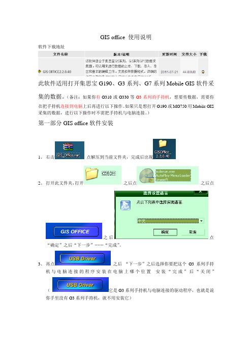
GIS office 使用说明软件下载地址此软件适用打开集思宝G190、G3系列、G7系列Mobile GIS软件采集的数据。
(备注:如果你有G310或G330等G3系列的手持机,想要传数据,需要你在把手持机连接到电脑上后再进行以下操作。
如果只是想打开G190或MG750用Mobile GIS 采集的数据,进行以下操作时不需把手持机与电脑连接。
)第一部分GIS office软件安装1、右击点解压到当前文件夹,完成后出现2、打开此文件夹,打开之后点之后点之后点“确定”之后“下一步”……“完成”。
3、再点之后“下一步”之后选择你要把这个G3系列手持机与电脑连接的程序安装在电脑上哪个位置安装“完成”后“关闭”(它是G3系列手持机与电脑连接的驱动程序,也就是说你手里没有G3系列手持机,就不用安装它)4、这几个不用管它。
之后点“退出”第二部分GIS office软件使用1、打开点“文件”A.如果你想打开用MG750采集的数据。
软件主界面点“设置“(扳手和螺丝刀图标)点“项目”(项目名称可改)之后点屏幕下方“返回”和“新建”中间那个九个实心方块组成的图标之后点“查看项目列表”“打开”点“数据个数”下边的格之后弹出所采集的数据。
把每个数据点开之后都“保存”一下。
返回点九个实心方块组成的图标,再点“GMT 导出”之后弹出对话框让你把导出的数据保存在某一位置,此时一般都点“返回上一级目录”把数据直接保存到“storage Card”里。
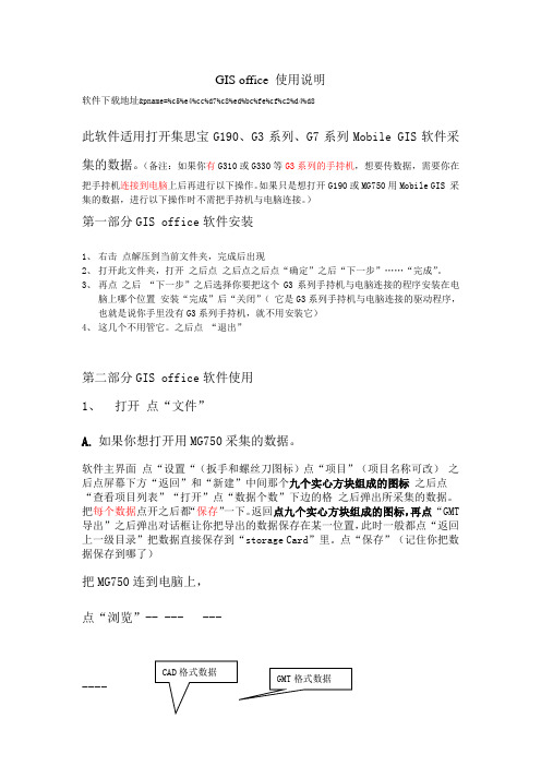
点“保存”(记住你把数据保存到哪了)把MG750连到电脑上,点“浏览”-- --- -------GMT格式数据CAD格式数据把GMT格式的数据复制到电脑桌面上,之后在GIS office 软件里点“文件”—“导入”文件类型选成.gmt格式在桌面上找到gmt文件,打开。
B、如果你想看你用G3系列手持机采集的数据。
点“文件”“从手持机接收”选成USB之后点“文件”“连接”之后在左侧就会出现以日期为文件名的数据。
ARCGIS使用手册
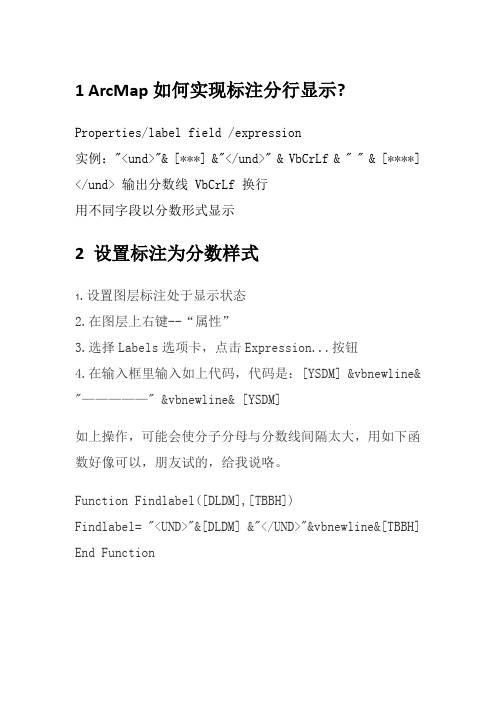
1 ArcMap如何实现标注分行显示?Properties/label field /expression实例:"<und>"& [***] &"</und>" & VbCrLf & " " & [****] </und> 输出分数线 VbCrLf 换行用不同字段以分数形式显示2 设置标注为分数样式1.设置图层标注处于显示状态2.在图层上右键--“属性”3.选择Labels选项卡,点击Expression...按钮4.在输入框里输入如上代码,代码是:[YSDM] &vbnewline& "—————" &vbnewline& [YSDM]如上操作,可能会使分子分母与分数线间隔太大,用如下函数好像可以,朋友试的,给我说咯。
Function Findlabel([DLDM],[TBBH])Findlabel= "<UND>"&[DLDM] &"</UND>"&vbnewline&[TBBH] End Function3ArcGIS9.3安装步骤ArcGIS Desktop 9.3安装流程1、打开安装文件夹,点击ESRI.exe文件,进入安装页面。
首先安装ArcGIS License Manager。
2、在弹出的Import License File对话框中,需要将Desktop 的破解文件导入,该文件位于安装文件"ArcGIS Desktop 9.3"ESRI ArcGIS Desktop 9.3 license文件夹中。
文件名为arcgis_tbe.lic。
3、然后一直Next到安装完成。
安装完成后要重新启动一次机器。
bigemap gis office使用方法
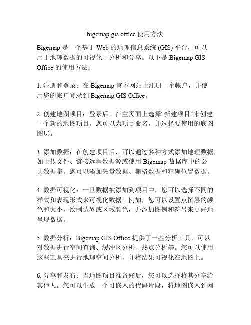
bigemap gis office使用方法Bigemap 是一个基于 Web 的地理信息系统 (GIS) 平台,可以用于地理数据的可视化、分析和分享。
以下是 Bigemap GIS Office 的使用方法:1. 注册和登录:在 Bigemap 官方网站上注册一个帐户,并使用您的帐户登录到 Bigemap GIS Office。
2. 创建地图项目:登录后,在主页面上选择“新建项目”来创建一个新的地图项目。
您可以为项目命名,并选择要使用的底图图层。
3. 添加数据:在创建项目后,可以通过多种方式添加地理数据,如上传文件、链接远程数据源或使用 Bigemap 数据库中的公共数据集。
您可以添加矢量数据、栅格数据和精确位置数据。
4. 数据可视化:一旦数据被添加到项目中,您可以选择不同的样式和表现形式来可视化数据。
例如,您可以设置点图层的颜色和大小,绘制边界或区域颜色,并添加图例和符号来更好地呈现数据。
5. 数据分析:Bigemap GIS Office 提供了一些分析工具,可以对数据进行空间查询、缓冲区分析、热点分析等。
您可以使用这些工具来进行地理空间分析,并将结果可视化在地图上。
6. 分享和发布:当地图项目准备好后,您可以选择将其分享给其他人。
您可以生成一个可嵌入的代码片段,将地图嵌入到网页中,或者将地图导出为常见的图像格式进行共享。
请注意,以上仅是 Bigemap GIS Office 的基本使用方法。
Bigemap 还提供了许多其他功能和高级工具,如多用户协作、地理编码和空间数据处理等。
如需进一步了解和探索 Bigemap 的功能,请查阅 Bigemap 的官方文档和教程资源。
GIS office使用说明

GIS office使用说明GIS office 使用说明软件下载地址;pname=%c5%e4%cc%d7%c8%ed%bc%fe%cf%c2%d4%d8此软件适用打开集思宝G190、G3系列、G7系列Mobile GIS软件采集的数据。
(备注:如果你有G310或G330等G3系列的手持机,想要传数据,需要你在把手持机连接到电脑上后再进行以下操作。
如果只是想打开G190或MG750用Mobile GIS 采集的数据,进行以下操作时不需把手持机与电脑连接。
)第一部分GIS office软件安装1、右击点解压到当前文件夹,完成后出现2、打开此文件夹,打开之后点之后点之后点“确定”之后“下一步”……“完成”。
3、再点之后“下一步”之后选择你要把这个G3系列手持机与电脑连接的程序安装在电脑上哪个位置安装“完成”后“关闭”( 它是G3系列手持机与电脑连接的驱动程序,也就是说你手里没有G3系列手持机,就不用安装它)4、这几个不用管它。
之后点“退出”第二部分GIS office软件使用1、打开点“文件”A. 如果你想打开用MG750采集的数据。
软件主界面点“设置“(扳手和螺丝刀图标)点“项目”(项目名称可改) 之后点屏幕下方“返回”和“新建”中间那个九个实心方块组成的图标之后点“查看项目列表”“打开”点“数据个数”下边的格之后弹出所采集的数据。
把每个数据点开之后都“保存”一下。
返回点九个实心方块组成的图标,再点“GMT导出”之后弹出对话框让你把导出的数据保存在某一位置,此时一般都点“返回storage Card”里。
点“保存”(记住你把数上一级目录”把数据直接保存到“据保存到哪了)把MG750连到电脑上,点“浏览”-- --- ---CAD格式数据GMT格式数据----把GMT格式的数据复制到电脑桌面上,之后在GIS office 软件里点“文件”—“导入”文件类型选成.gmt格式在桌面上找到gmt文件,打开。
gisoffice使用说明
GIS office 使用说明软件下载地址&pname=%c5%e4%cc%d7%c8%ed%bc%fe%cf%c2%d4%d8此软件适用打开集思宝G190、G3系列、G7系列Mobile GIS软件采集的数据。
(备注:如果你有G310或G330等G3系列的手持机,想要传数据,需要你在把手持机连接到电脑上后再进行以下操作。
如果只是想打开G190或MG750用Mobile GIS 采集的数据,进行以下操作时不需把手持机与电脑连接。
)第一部分GIS office软件安装1、右击点解压到当前文件夹,完成后出现2、打开此文件夹,打开之后点之后点之后点“确定”之后“下一步”……“完成”。
3、再点之后“下一步”之后选择你要把这个G3系列手持机与电脑连接的程序安装在电脑上哪个位置安装“完成”后“关闭”(它是G3系列手持机与电脑连接的驱动程序,也就是说你手里没有G3系列手持机,就不用安装它)4、这几个不用管它。
之后点“退出”第二部分GIS office软件使用1、打开点“文件”A.如果你想打开用MG750采集的数据。
软件主界面点“设置“(扳手和螺丝刀图标)点“项目”(项目名称可改)之后点屏幕下方“返回”和“新建”中间那个九个实心方块组成的图标之后点“查看项目列表”“打开”点“数据个数”下边的格之后弹出所采集的数据。
把每个数据点开之后都“保存”一下。
返回点九个实心方块组成的图标,再点“GMT 导出”之后弹出对话框让你把导出的数据保存在某一位置,此时一般都点“返回上一级目录”把数据直接保存到“storage Card”里。
点“保存”(记住你把数据保存到哪了)把MG750连到电脑上,点“浏览”-- --- -------把GMT 格式的数据复制到电脑桌面上,之后在GIS office 软件里点“文件”—“导入” 在桌面上找到gmt 文件,打开。
B 、如果你想看你用G3系列手持机采集的数据。
点“文件”“从手持机接收” 之后点“文件”“连接” 之后选中你想看的那天的数据右键,点“文件”“导入” 弹出找到你之前复制 保存的数据。
ArcGIS for Microsoft Planetary Computer 使用指南说明书

Getting Started with ArcGIS for Microsoft Planetary Computer July 1, 2023Copyright © 2023Esri All rightsreserved.Printed in the United States of America.The information contained in this document is the exclusive property of Esri. This work is protected under United States copyright law and other international copyright treaties and conventions. No part of this work may be reproduced or transmitted in any form or by any means, electronic or mechanical, including photocopying and recording, or by any information storage or retrieval system, except as expressly permitted in writing by Esri. All requests should be sent to Attention: Contracts and Legal Services Manager, Esri, 380 New York Street, Redlands, CA 92373-8100 USA.The information contained in this document is subject to change without notice.Esri, the Esri globe logo, The Science of Where, ArcGIS, ,*************************,servicemarks,orregistered marks of Esri in the United States, the European Community, or certain other jurisdictions. Other companies and products or services mentioned herein may be trademarks, service marks, or registered marks of their respective mark owners. Contents1.0 Introduction (4)2.0 Configuring ArcGIS for Microsoft Planetary Computer (4)Tab 1 Basics (7)Project Details (7)Instance Details (7)Administrator Account (7)Tab 2 (Virtual Machine Settings) (8)Disk Settings (8)Networking (8)Configure Virtual networks (8)Tab 3 (Management Settings) (9)Configure management options for your VM (9)3.0 Starting and Stopping the Virtual Machine (14)3.1 Managing Your Virtual Machine (15)3.2 Deleting the Virtual Machine (15)3.3 Accessing the ArcGIS Pro Virtual Desktop (15)1.0IntroductionArcGIS for Microsoft Planetary Computer is a new offering from Esri that brings hundreds of ready-to-use analysis tools from ArcGIS to the Microsoft Planetary Computer so users can observe and monitor the planet. ArcGIS for Microsoft Planetary Computer spins up a virtual ArcGIS Pro virtual machine on demand in the cloud that offers all the capabilities the user has licensed for ArcGIS Pro—including its raster analytics tools, geoprocessing tools, publishing tools, as well as any extensions the user has purchased.With ArcGIS for Microsoft Planetary Computer, users can apply image processing and raster analytics tools from ArcGIS Pro to support workflows such as:•Suitability assessment to find the best sites for conservation and agriculture•Change detection to locate areas impacted by disasters, identify new urban development, monitor sea level changes, and update trend forecasts•Susceptibility analysis to identify areas at risk of fires, floods, and other disasters•AI and machine learning workflows like land cover classification and object detection 2.0Configuring ArcGIS for Microsoft Planetary ComputerThe Microsoft (MS) Planetary Computer is an Analysis platform that allows for Analysts to leverage cloud computer services and a catalog of petabytes of Earth Science data layers. To access these resources using ArcGIS, you will need to have your own Azure cloud account. Please see the Microsoft Azure documentation or technical support team if you need help setting up and configuring that account before you proceed.Creating a New ArcGIS for Microsoft Planetary Computer Instancea)Navigate the azure marketplace and search for the “ArcGIS for Microsoft PlanetaryComputer”. This should bring you to a page with the ArcGIS for Microsoft PlanetaryComputer card. Click on “Get it now”Fig 2a.b)This initializes your setup – and lets you continue the process when you accept the terms ofuse.Fig 2b.Hit “Continue”. This takes you to the ArcGIS for Microsoft Planetary Computer landing page.c)Hit “Create” next to the ArcGIS for Planetary computer drop down selector as shown.Fig 2c.d)This will direct you to the solution template/wizard to create your new instance. Here you willsee Four tabs at the top: Basics, Virtual Machine Settings, Management Settings, and Review + Create. This is the configuration sequence you will follow as you step through the template.Fig 2d.Tab 1 BasicsBelow is some additional information to help the user understand the options that are available in this configuration tab.Project DetailsSubscriptionPick the Azure subscription you would like to use for this project (VM). This is also the account that will be billed by Microsoft (for use of this instance).Resource GroupThis is usually defined by an administrator, if the account has predetermined permissions or policies. Or you can just create new, and provide a resource group (think of it like a folder)Instance DetailsRegions – This option is non-selectable. Because the Planetary Computer data catalog resides only in the West Europe Region, creating and using a Virtual Machine in the same region eliminates latency in data transfer and removes data movement charges.Virtual Machine Name–Here’s where the user names the VM. A pre-defined name is selected by default.Size– The default (NV8as_V4) instance is an 8-core 28GB RAM, dedicated Graphics Processing Unit (GPU) instance. Some Analysis tasks may require higher level computing instances. If you prefer more compute resources, you can click “Change size” option. This selection provides a list of compatible and recommended instances for you to choose.Administrator AccountThis is a new administrator account that is needed for this virtual windows machine, and includes the credentials (username, password) you will be using to log into the virtual machine.Fig 2e.Scroll down and hit NextTab 2 (Virtual Machine Settings)Disk SettingsFor this portion of the template, the default settings should be adequate for most users, however, you may configure the options if needed. (At a later point through azure console users can attach their own disks)NetworkingPublic IP Address (default in most cases)Unless otherwise indicated by your organization, you should use the default setting for this option. System administrators may want to consider restricting the inbound IPs to enhance performance. This can be done using the Azure user dashboard.Configure Virtual networksFor this portion of the template, the default settings should be adequate for most users, in some cases however, there is some organization-specific information that needs to be entered here. In most cases, these were pre- configured by your System Administrator when your Azure account was established and is associated with the selected resource group from Tab 1, in which case you do nothave to make any changesVirtual Network– you can pick an existing network or create a new network if you have the appropriate organizational permissions.Subnet–This is part of the virtual network configuration and should be pre-defined by your System Administrator.Fig 2f.Scroll down and hit nextTab 3 (Management Settings)Configure management options for your VMA note about auto-shutdown. It is highly recommended that you keep this setting selected. Auto shutdown is used to make sure a user does not accidentally let an instance run longer than it should, which can lead to unwanted compute costs. Provide an email id where you would want to receive notifications about your instanceFig 2g.Scroll down and hit the “Next: Review + c reate” button to move to the next template tabTab 4: Review + CreateThis tab allows for you to see your settings, and confirm they are correct. They are automaticallyvalidated by the system for any errors.Fig 2h.Hit the “Create” button to complete the process. It may take upto five minutes for the new virtual machine to be completed.Once done –hit “Go to resource group”Fig 2i.This will take you to your resources for the instance.Fig 2j.Click on the Virtual machine ( vina-ampc-vm in Figure 2k). It’s the name you specified when creating the instanceFig 2k.This takes you to the dashboard, where you can manage your instance, delete your instance, start your instance, connect to your instance and so on.You can click on connect at this point (highlighted in Fig 2L. below)Fig 2L.3.0Starting and Stopping the Virtual MachineYou can start or stop the VMs whenever you choose. Ideally, you might want to stop a machine when it is not in use to prevent incurring unwanted cost and start it up again when you would like to work. Follow these steps to start and stop your virtual machine:a)Navigate to your portal. https:///b)Either click on the resource (as in Figure 2K) and follow steps to start your instance andremote in or click on the VM name as in Figure 3b belowFig 3b.c)This will take you to the instance portal to manage the instance.Fig 3c.d)Hit “C onnect”, as shown in Figure 3c above. here’s where you can download the remotedesktop protocol (RDP) connection file to your local machine.e)once downloaded, you can connect to the new virtual machine by keying in yourAdministrator credentials that you specified when creating the instance.3.1 Managing Your Virtual Machinea)Navigate to your Azure portal webpage ()b)Select “Virtual Machines”. You should now see the machine you created using theConfiguration template listed.c)Click on the instance; a new dashboard will appear that gives you control of the virtualmachine. Here you can modify settings, start the instance, delete the instance, review logs,attach disks, etc.3.2Deleting the Virtual MachineWhen you have completed your Analysis using the ArcGIS virtual machine, you can delete your instance using the same portal dashboard where you started and connected to the machine.3.3Accessing the ArcGIS Pro Virtual DesktopWhen you create an ArcGIS for Planetary Computer Machine and log into the account, you will see what looks like a typical windows desktop configuration. However, there are still some steps to complete before you can begin your Analysis.a)Just like on a normal desktop machine, ArcGIS for Microsoft Planetary Computerrequires an ArcGIS PrO license for the software to work. However, Users can use theirexisting licenses from an existing ArcGIS pro system. All license types are applicable:single user, concurrent user, or named user license. The license level can be Basic,Standard or Advanced and can include any ArcGIS Pro extensions for additionalprocessing such as such as Image Analyst. The type of license the user connects tothis system will determine the functionality that is available for processing in thisenvironment.b)The C drive configured for the virtual machine contains two folders with specializedtools and connection files designed to work with the Planetary Computer data.•ACSFiles - This folder contains the pre-created cloud storage connection files (ACS) that identify the public datasets available at Microsoft’s PlanetaryComputer Data Catalog, so they are visible to the users directly within theCatalog view. These are cloud region specific, so can only be used in thissetting.•Image_Mgmt_Workflows – This folder contains the raster templates needed to build mosaic datasets and analyze the data catalog files within this ArcGISpro instance.Note: Do not delete or rename the folders mentioned above.。
MAPGIS实用方法及技巧(全)
一、如何将mapgis的图形插到word、excel、PowerPoint 中首先点取mapgis菜单“其他->OLE拷贝”,接着打开word,点取“粘贴”。
Mapgis 数据就复制到word文档里。
二、空心字格式使用空心字时,字体采用相应字体编号的负数。
如:-3表示黑体空心字。
三、合并区1、可以在屏幕上开一个窗口,系统就会将窗口内的所有区合并,合并后区的图形参数及属性与左键弹起时所在的区相同。
2、也可以先用菜单中的选择区功能将要合并的区拾取到,然后再使用合并区功能实现。
3、还可以先用光标单击一个区,然后按住 CTRL 键,在用光标单击相邻的区即可。
四、翻转图形在Mapgis中的其它下面整图变换中比例参数的X比例中输入法-1或Y比例中输入-1后确定。
五、CAD转化为MAPGIS1.将CAD文件另存为2004/2000DXF格式。
2.在MAPGIS主程序中选择“文件转换”。
3.输入中选择转入DXF文件,确定并复位4.保存点线文件(面无法转化)六、MAPGIS转化为CAD1.在MAPGIS主程序中选择“文件转换”。
2.分别装入点线文件,复位并全选。
3.输出中选择“部分图形方式输入DXF”全选并确定。
4.打开保存的DXF文件,用CAD复位显示图形,并改字体样式。
5.保存成CAD格式。
七、如何把JPG格式的转成MSI格式图象处理----------图象分析模块。
在里面点:文件--------数据输入--------转换数据类型(选JPG)---------添加文件---------转换转换后的格式为mapgis的msi影像文件!转换为MSI文件格式后再在输入编辑里,导入后矢量化。
八、在电脑里如何做剖面图,不用手画,而且精度更高!1、先把MAPGIS图生成JPG格式,在PHOTOSHOP中图像—图像大小—文挡大小中输入经过变化后的宽度和高度数字(根据剖面图的比例和JPG图的比例关系得出);然后按需要裁剪,以减少图形的所占内存;2、裁剪后旋转使剖面线处于水平位置;3、在MAPGIS中插入裁剪旋转后光栅文件,新建线和点文件,以剖面线为水平的X轴,画垂直X轴的线为Y轴,以剖面线起点的位置为坐标原点,以剖面线起点的高程为起始Y 轴刻度,在X和Y轴上标上相对应比例尺的刻度。
MAPGIS操作手册下2
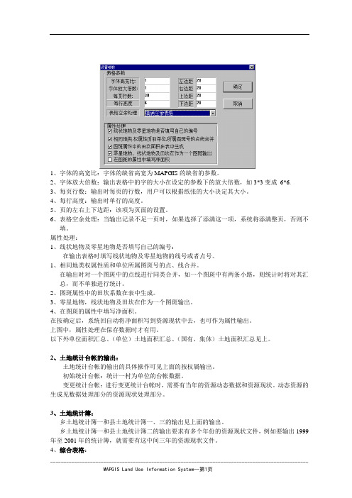
1、字体的高宽比:字体的缺省高宽为MAPGIS的缺省的参数。
2、字体放大倍数:输出表格中的字的大小在设定的参数下的放大倍数,如3*3变成6*6.3、每页行数:输出时每页的行数,用户可以根据纸张的大小决定其大小。
4、每行高度:输出时单行的高度。
5、页的左右上下边距:该项为页面的设置。
6、表格空余处理:当输出记录不足一页时,如果选择了添满这一项,系统将添满整页,否则不填。
属性处理:1、线状地物及零星地物是否填写自己的编号:在输出表格时填写线状地物及零星地物的线号或者点号。
1、相同地类权属性质和单位所属图斑号的点、线合并。
在输出时对一个图斑中的点线进行同类合并,如一个图斑中有两条小路,则统计时将对其汇总,而不单独进行统计。
2、图斑属性中的田坎系数在表中生成。
3、零星地物,线状地物及田坎在作为一个图斑输出。
4、在图斑的属性中填写净面积。
在按确定后,系统回自动将净面积写到资源现状中去,也可作为属性输出。
上图中,属性处理在保存数据时才有用。
以下外单位面积汇总、(单位)土地面积汇总、(国有、集体)土地面积汇总见上。
2、土地统计台帐的输出:土地统计台帐的输出的具体操作可见上面的按权属输出。
初始统计台帐:统计一村为单位的台帐数据。
变更统计台帐:进行变更统计台帐时,需要有当年的资源动态数据和资源现状。
动态资源的生成见数据处理部分的资源现状处理部分。
3、土地统计簿:乡土地统计簿一和县土地统计簿一、三的输出见上面的输出。
乡土地统计簿一和县土地统计簿二的输出要求有多个年份的资源现状文件,例如要输出1999年至2001年的统计簿,就需要有这中间三年的资源现状文件。
4、综合表格:4.6.7、境界输出如下图示:选择该菜单后弹出如图对话框,用户可以选择要生成的境界的类型:乡界、村界或县界。
设置生成的线文件的参数等,就可以进行。
参数:用户可以在此设置系统的输出参数,即点、线的参数,具体操作见第一章。
注:系统在处理时,是通过判断所打开的文件中是否有行政代码来判断可否生成境界,并不要求要哪个具体的文件。
Arcgis使用说明
空间查询是地理信息系统以及许多其他自动化地理数据处理系统应具备的最基本的 分析功能。而空间分析是地理信息系统的核心功能, 也是地理信息系统与其他计算机系 统的根本区别。模型分析是在地理信息系统支持下, 分析和解决现实世界中与空间相关 的问题, 它是地理信息系统应用深化的重要标志。
地理信息系统以数字形式表示自然界, 具有完备的空间特性, 它可以存储和处理不 同地理发展时期的大量地理数据, 具有极强的空间信息综合分析能力, 是地理分析的有 力工具。地理信息系统不仅要完成管理大量复杂的地理数据的任务, 更为重要的是要完 成地理分析、评价、预测和辅助决策的任务。因此, 研究广泛适用于地理信息系统的地 理分析模型, 是地理信息系统真正走向实用的关键。
3. 系统开发、管理与使用人员
人是构成 GIS 重要的因素。地理信息系统从其设计、建立、运行到维护的整个生 命周期, 处处都离不开人的作用。仅有系统软硬件和数据还不能构成完整的地理信息系 统, 还需要人进行系统组织、管理、维护和数据更新, 以及系统扩充完善、应用程序开 发, 并灵活采用地理分析模型提取多种信息, 为研究和决策服务。地理信息系统专业人 员是地理信息系统应用的关键, 而强有力的组织是系统运行的保障。
地理信息系统的大容量、高效率及其结合的相关学科的推动使其具有运筹帷幄的优 势, 成为国家宏观决策和区域多目标开发的重要技术支撑, 也成为与空间信息有关各行 各业的基本分析工具。其强大的空间分析功能及 发展潜力 使得 G IS 在测绘 与地图 制图、 资源管理、城乡规划、灾害预测、土地调查与环境管理、国防、宏观决策等方面得到广 泛、深入的应用。
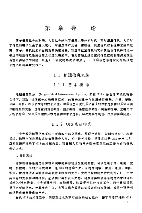
1. 硬件系统
计算机硬件系统是计算机系统中的实际物理配置的总称, 可以是电子的、电的、磁 的、机械的、光的元件或装置, 是 GIS 的 物理外壳。系 统的 规模、精 度、速 度、功能、 形式、使用方法甚至软件都与硬件有极大的关系, 受硬件指标的支持或制约。 GIS 由 于 其任务的复杂性和特殊性, 必须由计算机设备支持。构成计算机硬件系统的基本组件包 括输入/ 输出设备、中央处理单元、存储 器等。这 些硬 件组 件协同 工作, 向计算 机系 统 提供必要的信息, 使其完成任务, 也可以保存数据以备现在或将来使用, 或将处理得到 的结果或信息提供给用户。
GIS使用说明
∙要素类∙属性表∙栅格数据集这三个基本的数据类型可通过增加一些功能而进行扩展,以管理数据的完整性、建立地理关系的模型(如网络连通性和流向)并添加重要的地理行为。
每个GIS 都有一组数据集通常,GIS 用于处理若干不同的数据集,其中每个数据集都包含关于特定要素集合(例如,道路)的数据,而特定要素集合则被地理引用到地球表面。
GIS 数据库根据一系列数据专题而设计,每一专题均有指定的地理制图表达。
例如,单个的地理实体可表示为以下内容:要素(如点、线和面),使用栅格的影像,使用要素、栅格或TIN 的表面,以及保存在表格里的描述性属性。
在GIS 中,地理对象的同类集合被组织为宗地、井、建筑物、正射影像和基于栅格的数字高程模型(DEM) 等数据专题。
精确而简单定义的地理数据集对于有用的地理信息系统是至关重要的,而基于图层的数据专题的设计则是一个关键的GIS 概念。
GIS 数据集是地理要素的逻辑集合数据集是每一专题同类要素的集合。
地理制图表达在一系列数据集或图层中进行组织。
大多数数据集是道路网络、宗地边界集合、土壤类型、高程表面、某个日期的卫星影像、井位或地表水等简单地理元素的集合。
在GIS 中,空间数据集合通常被组织为要素类数据集或基于栅格的数据集。
许多数据专题最好使用土壤类型或井位等单一数据集表示。
其他专题,如交通框架或表面高程,经常使用多个数据集表示。
例如,交通可能被表示为街道、十字路口、桥梁、高速公路坡道、铁路等多个要素类。
下表说明了如何使用多个数据集来表示表面高程。
栅格数据集用于表示地理配准影像及高程、坡度和坡向等连续表面。
专题图层变为数据集。
这是GIS 数据库中的关键组织原则。
每个GIS 的公共地理区域中都将含有多个专题。
专题的集合用作图层的堆叠。
每个专题均可作为独立于其他专题的信息集进行管理。
每个专题都有自己的制图表达(作为点、线、面、表面、栅格等的集合)。
因为图层是空间参考的,所以图层互相叠加并且可以在常用地图显示里组合在一起。
- 1、下载文档前请自行甄别文档内容的完整性,平台不提供额外的编辑、内容补充、找答案等附加服务。
- 2、"仅部分预览"的文档,不可在线预览部分如存在完整性等问题,可反馈申请退款(可完整预览的文档不适用该条件!)。
- 3、如文档侵犯您的权益,请联系客服反馈,我们会尽快为您处理(人工客服工作时间:9:00-18:30)。
GIS office 使用说明
软件下载地址
/Service/dchannel.aspx?moduleid=303&pname=%c5%e4%cc%d7%c8%ed%bc%fe%c f%c2%d4%d8
此软件适用打开集思宝G190、G3系列、G7系列Mobile GIS软件采集的数据。
(备注:如果你有G310或G330等G3系列的手持机,想要传数据,需要你
在把手持机连接到电脑上后再进行以下操作。
如果只是想打开G190或MG750用Mobile GIS 采集的数据,进行以下操作时不需把手持机与电脑连接。
)
第一部分GIS office软件安装
1、右击点解压到当前文件夹,完成后出现
2、打开此文件夹,打开之后点之后点
之后点“确定”之后“下一步”……“完成”。
3、再点之后“下一步”之后选择你要把这个G3系列手持
机与电脑连接的程序安装在电脑上哪个位置安装“完成”后“关闭”
(它是G3系列手持机与电脑连接的驱动程序,也就是说你手里没有G3系列手持机,就不用安装它)
4、这几个不用管它。
之后点“退出”第二部分GIS office软件使用
1、打开点“文件”
A.如果你想打开用MG750采集的数据。
软件主界面点“设置“(扳手和螺丝刀图标)点“项目”(项目名称可改)之后点屏幕下方“返回”和“新建”中间那个九个实心方块组成的图标之后点“查看项目列表”“打开”点“数据个数”下边的格之后弹出所采集的数据。
把每个数据点开之后都“保存”一下。
返回点九个实心方块组成的图标,再点“GMT 导出”之后弹出对话框让你把导出的数据保存在某一位置,此时一般都点“返回上一级目录”把数据直接保存到“storage Card”里。
点“保存”(记住你把数据保存到哪了)
把MG750连到电脑上,
点“浏览”-- --- ---
----
GMT格式数据CAD格式数据
把GMT格式的数据复制到电脑桌面上,之后在GIS office 软件里点“文件”—“导入”
文件类型选
成.gmt格式
在桌面上找到gmt文件,打开。
B、如果你想看你用G3系列手持机采集的数据。
点“文件”“从手持
机接收”
选成USB
之后点“文件”“连接”之后在左侧就会出现以日期为文件名的数据。
之后选中你想看的那天的数据右键,“复制”(注意:右侧就是你把数
据复制后保存的位置)之后关闭这个对话框。
在
点“文件”“导入”弹出
文件类型选成.gmt格式
找到你之前复制保存的数据。
之后打开
怎么修饰面积图形?
在图形边缘单击一下之后右键单击出现之后双击右侧弹出自选。
常用工具说明
下面说一下,怎么在图上添加备注信息。
点一下
在图上空白处点一下,就创建了一个点。
再点一下
光
标就变成正常的了。
捕捉移动图形
创建点,可以添加备注信息
如果你的电脑安装了google earth 点击此图标,你所测的图会在航拍地图上显示。
点“文件”可打印。