宽带匹配
天线宽带匹配网络的设计与计算方法
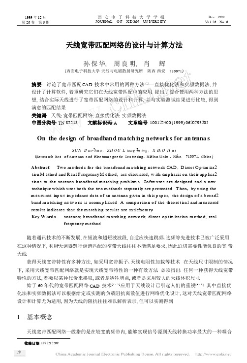
1999 年12 月第26 卷第6 期西安电子科技大学学报JO U RNAL O F X I D I A N UN I V ERS I TYD e c. 1999Vo l.26No. 6天线宽带匹配网络的设计与计算方法孙保华, 周良明, 肖辉(西安电子科技大学天线与电磁散射研究所陕西西安710071)摘要: 讨论了宽带匹配CA D技术中常用的两种方法——直接优化法和实频数据法, 并设计了计算软件, 着重研究它们在天线宽带匹配中的应用. 提出了综合使用两种方法的思想, 结合实际天线进行了宽带匹配网络的设计和计算, 并与实验测试结果进行比较, 得到满意的匹配结果.关键词: 天线; 宽带匹配网络; 直接优化法; 实频数据法中图分类号: TN 82218文献标识码: A 文章编号: 100122400 (1999) 0620793205On the de s ign of broa dban d m a tch i n g n e twork s f or an tenna sS U N B a o2h u a , Z H OU L ia n g2m in g , X IA O H u i(Re se a rc h I n s t.o f A n t e nna a nd Ele c t r om a g n e t i c Sc a t t e ring , Xid ia n U n iv. , Xi′a n710071, C h i na )A b strac t: Tw o m e t ho d s fo r th e b ro a dband m a tch ing ne t w o rk CA D, D irec t O p t i m iza2t i o n M e t ho d and R ea l F requency M e t ho d, a re d iscu ssed, w ith em p h a sis o n th e i r app lica2t i o n s to th e an tenna b ro a dband m a tch ing p ro b lem s. So f t w a re s a re de s igned and a newtech n ique w h ich u se s bo th th e tw o m e t ho d s sequen t l y a re p re s en ted. T h e n ,by u sing th em ea su red inp u t i m p edance da ta o f an an tenna g iven in th is p ap e r, th e de sign o f a b ro ad2band m a tch ing ne tw o rk is accom p lish ed. A com p a r iso n o f th e th eo re t ica l and m ea su redre s u lt s ind ica te s th a t th e m a tch ing re s u lt s a re sa t i sfac t o ry.Key W ord s: a n tenna; b ro a dband m a tch ing ne t w o rk; d irec t op t i m iza t i o n m e t ho d; rea lf r equency m e t ho d随着通讯技术的不断发展, 在短波和超短波波段, 自适应快速跳频、选频等先进技术已被广泛采用. 在这种情况下, 利用“天调器”进行调谐匹配的窄带天线往往不能满足要求, 因此迫切需要性能优良的宽带天线.获得天线宽带特性有多种方法, 如采用宽带振子、天线电阻性加载等技术. 在天线尺寸限制的情况下, 采用天线宽带匹配网络就是实现天线宽带特性的一种有效方法. 必须指出: 任何一种获得天线宽带特性的方法, 都要以某种代价来换取, 或者是牺牲增益, 或者是采用较大的天线体积尺寸.始于60 年代的宽带匹配网络CA D技术[ 1~3 ] 应用于天线设计已引起人们的重视[ 4~6 ]. 其中直接优化法和实频数据法可以根据给定或实测的负载阻抗离散值进行网络优化设计, 这对天线宽带匹配网络设计和计算尤为适用, 因为天线的阻抗往往难以解析表示, 但可以实测得到.1基本概念天线宽带匹配网络一般指的是在较宽的频带内, 能够实现信号源到天线转换功率最大的一种耦合收稿日期: 1998212209基金项目:“八五”国防预研项目( 19121513)作者简介: 孙保华( 19692) , 男, 西安电子科技大学博士生.12.794西安电子科技大学学报第26 卷网络. 对于这样的网络, 必须具有如下特点: (1) 输出端与负载端有良好的匹配; (2) 输入端的反射尽可能小; (3) 网络本身无耗或低耗. 图1 所示即为包含宽带匹配网络的模型. 图中r g 为信号源内阻, Z a 为天线输入阻抗, N 表示天线宽带匹配网络, 它一般是由电容、电感和理想阻抗变r g换器组成的无耗互易二端口网络~研究天线宽带匹配网络, 通常使用的能够表征匹配的参Ug量主要有转换功率增益和电压驻波比.Z cZ 111�宽带·匹配网络Z aNZ q2 转换功率增益定义为负载得到的平均功率和信号源能够给出的最大平均功率之比[ 7 ] , 公式表示为图1 天线系统模型G =P , (1)P av式中P 为负载得到的平均功率, P av 为信号源能够给出的最大平均功率, 即信号源资用功率.工程中通常使用的信号源阻抗和馈线特性阻抗为50 8. 图1 所示的天线系统, 在端口1 有R = , (2)式中# =50.图1 所示天线系统中, 考虑到宽带匹配网络是一个无耗互易二端口网络, G 和R 存在如下关系:R =1 + (1 - G ). (3)1 - (1 - G ) 122直接优化法和实频数据法211直接优化法实用当中, 宽带匹配网络的元件个数一般不超过6 个[ 5 ]. 对6 个元件以内的L C 网络可分为T 型和0 型两种结构形式, 对每一个支节约定如下:(1) 短路不作为并联支路.(2) 开路不作为串联支路.(3) L C 串联不作为并联支路.(4) L C 并联不作为串联支路.这样, 6 个元件以内的网络形式总共有78 种.参看图1, 在端口1, 有R (Ξi )= , (4)其中# (Ξi )= , i = 1, 2, ⋯,M . (5)Ξi 为选定的带内M 个频率点, Z 11 (Ξi )为馈电端口看去的阻抗值.由式(4)、(5) 可看出, R (Ξi ) 和 # (Ξi )的变化规律是一致的, 即为了使得带内R 最小, 可以通过优化带内 # 最小得以实现. 而使用后者较为方便, 故目标函数选为ME (p 1 , p 2 , p 3 ) = ∑W (Ξi ) # (Ξi ) 2 = 最小, (6)i= 1其中p 1 , p 2 , p 3 分别代表T 型或0 型网络各个支节上的电容、电感元件值; W (Ξi )为加权函数, 可以使用指数加权、平均加权等多种形式, 1. 指数加权函数为W (Ξi ) =[R (Ξi ) ]e R (Ξi ) ≥v ,(7) v 和e 为指定的两个常数. 这里使用加权函数的目的是: 不同问题选择合适的加权函数, 可以改善优化计q q qq ( ∞ 第 6 期 孙保华等: 天线宽带匹配网络的设计与计算方法795算的收敛速度和优化结果.由于目标函数 E (p 1 , p 2 , p 3 ) 是可导函数, 优化计算可以采用多 �种方法. 计算表明, 采用B F G S 优化算法, 收敛速度快, 且稳定性也较 好.T 01∶K在直接优化法设计的网络中, 引入一个给定变换比的阻抗变换 Z a器, 如图 2 所示. 图 2 中的 1∶K 表示阻抗变换器的变换比. 这样, 依据以上原理编程, 通过一个程序即可完成 78 种网络的直接优化 宽带 ·· · 匹配网络设计.212 实频数据法参看图 1, 从端口 2 看去的阻抗函数记为 Z q (s ) , 称为策动点阻 抗函数. 在复平面内有图2 T 型和0 型网引入阻抗变换器Z q (s ) s = j Ξ= Z q ( j Ξ) = R q (Ξ) + j X (Ξ) .(8)若 Z q (s ) 为最小虚部函数, R q (Ξ) 和 X q (Ξ) 满足[ 6 ]R q (Ξ) = R q (∞) - 1∞X q (Κ)d Κ ,X q (Ξ) = 1Π∫- ∞ Κ- Ξ R q (Κ) d Κ ,(9)Π∫- ∞ Κ- Ξ 上式称为 H ilbe r t 变换对. 利用此式, 求解 Z q (s ) 只需要找到 R q (Ξ) 和 X q (Ξ) 中的一个即可.在端口 2, G 可以表示为G =4 R q (Ξ) R a (Ξ).(10)[R q (Ξ) + R a (Ξ) ]2 + [X q (Ξ) + X a (Ξ) ]2实频数据法 (R FM ) 的基本思想是: 利用优化算法, 寻找待求的 R q (Ξ) , 使得带内G 最大最平坦; 再由 找到的 R q (Ξ) 求解 Z q (s ) , 最后根据 Z q (s ) 综合出网络元件值. 为此优化计算中目标函数选取为ME =∑ (G- G (Ξi ) ) 2 = 最小 ,(11)i = 1式中的 G 0 称为参考 G , 为 0~ 1 之间的常 数. 计算过程中, 不同的问题选择不同的 G 0 可以得到最佳的优化结果.R FM 具体实现步骤如下:(1) 用折线 R δ (Ξ) 逼近待求的 R q(Ξ). 尽 管式 ( 9) 给出了 R q (Ξ) 和 X q (Ξ) 的 相 互 变 换 关 系, 但 由 于 积 分 限 由- ∞ 到+ ∞, 利用式 (9) 对任意的 R q (Ξ) 和 X q (Ξ)进行相互换算很困难. 为此, 用折射 R δ(Ξ) 逼近待求的连续策动点电阻函数 R q (Ξ). 如 图 3 所示, 设 Ξ1 , Ξ2 , ⋯, ΞN 为频率轴上的N 个间断点, 简称断点频率.NR δ(Ξ) = R 0 + ∑ a k (Ξ) r k , (12)k = 1 图 3 折线 R δ (Ξ) 和待求 R q(Ξ)式中 R 0 = R δ(0) , r 1 , r 2 , ⋯, r n 为断点之间 R δ Ξ) 的代数差值. 利用插值公式求系数 a k (Ξ) , 有1 , Ξ ≥ Ξk ,Ξ - Ξk - 1a k (Ξ) =Ξk - Ξk - 1,Ξk - 1 < Ξ ≤ Ξk , (13)q利用式(9) 计算Xδ(Ξ), 得0, Ξ< Ξk - 1 .q q q =Ra796 西安电子科技大学学报 第 26 卷系数 b k (Ξ) 为b k (Ξ) =1 Π (Ξk - Ξk - 1 )NX δ (Ξ) =∑ bk(Ξ) r k ,(14)k = 1[ (Ξ + Ξk ) ln (Ξ + Ξk ) + (Ξ - Ξk ) ln (Ξ - Ξk ) - (Ξ + Ξk + 1 ) ln (Ξ + Ξk + 1 ) + (Ξ - Ξk + 1 ) ln (Ξ - Ξk + 1 ) ] .(15)将 R δ (Ξ) , X δ (Ξ) 及天线阻抗 Z a ( j Ξ) = R a (Ξ) + j X a(Ξ) 代入式 (10) 得 q q N4R a (Ξ) R 0 +∑ a k(Ξ) rkk = 1G NN2. (16)2R a (Ξ) + R 0 +∑ a k(Ξ) rkk = 1+ X a (Ξ) +∑ bk(Ξ) r kk = 1频带内取M 个频率点 (Ξi , i = 1, 2, ⋯,M ) , 并使这些频率点对应于给定的或实测的阻抗数据频率,称作抽样频率. 利用最小二乘法, 以式 (11) 为目标函数进行优化计算, 得到对应于最佳G 的 R δ (Ξ). (2) 有理函数 R ϖ (Ξ) 拟合折线 R δ (Ξ). q q折线表示的 R δ (Ξ) 往往不能用有限元件组成的网络实现, 为此还需要寻找这样的一个 R ϖ (Ξ) , 满足 q q(a ) Rϖ (Ξ) 能够用有限元件组成的网络实现; (b) R ϖ (Ξ) 拟合 R δ Ξ , 从而保证该网络 G 接近步骤 1 中 R δ Ξ 所能达到的最佳 G .q q ( ) R ϖ ( ) q ( ) q (Ξ) 可以采用有理函数形式, 即RϖA Ξ2 k. (17)q(Ξ) =1 + B 1 Ξ2 + ⋯ + B N Ξ2N该函数对应于工程上采用的 T 型网络结构. 设计结果发现: k = 0, 得到的网络为低通形式; 0 < k < N ,得到的网络为带通形式; k = N , 得到的网络为高通形式.(3) 计算 Z q (s ) 并综合网络.由 R ϖ (Ξ) 求解 Z q (s ) 可以采用盖维茨方法[ 6 ]; Z q(s ) 综合网络采用分式连除法. 以低通网络为例, 有 Z q (Ξ) =1 .(18)j Ξ C 1 +1j Ξ L 1 +1 ω +1R直接优化法和实频数据法相比较, 直接优化法原理简单、方法直观. 但针对预设的网络拓扑优化设 计, 如果网络拓扑选择不当, 可能导致最优解被排除在可行域之外. 笔者介绍的直接优化法, 可以枚举78 种工程常用的网络结构, 在一定程度上弥补了这一缺陷. 实频数据法中, 待设网络用其策动点阻抗函数表示, 从根本上克服了直接优化法的缺陷. 但由计算过程不难看出, 实频数据法的计算比较复杂, 且设 计得到的网络包含任意的比阻抗变换器, 往往会给实用带来一定的麻烦. 为此, 在实际设计时, 可以综合 使用两种方法, 即① 利用实频数据法设计宽带匹配网络, 该匹配网络包含一组抗变换器, 变换比为 1∶K 0.② 选定阻抗变换器, 其变换比为 1∶K , 且 1∶K 与 1∶K 0 较为接近, 同时工程实用中易于制作, 再 利用直接优化法进行二次设计, 网络形式与实频数据法相同.�L 3 设计与计算L 2Z一套筒天线, 在 f = 9~ 27 M H z 频带内 R ≤ 3, 具有良好的 宽带特性. 且在f = 3~ 9 M H z 频带范围内其驻波值很高, 实测时一般 R ≥ 10. 其电阻值很小、电抗很大, 为了覆盖整个短波频段, 就要求在f = 3~9 M H z范围进行匹配. 在这种情况下, 只有采用宽带匹配网络. 附加网络 C 1T ·L 1图4 网络结构第6 期孙保华等: 天线宽带匹配网络的设计与计算方法797由套筒天线在f = 3~30 M H z 阻抗实测值, 可以看出天线阻抗在f = 3~9 M H z具有小电阻、大容抗的特性. 根据测得阻抗直接设计宽带匹配网络难以达到R ≤310 的要求, 为此需采用一附加网络以利于匹配(见图4). 利用实频数据法设计宽带匹配网络, 网络结构如图4 所示, 元件值如表1. 可以看到, 该网络中使用了1173∶1 的阻抗变换器. 考虑到该阻抗变换器制作较为困难, 而7550 8 阻抗变换器已被广泛使用, 两者差别不大, 故选定K = 115∶1. 利用直接优化法设计宽带匹配网直接优但已满足设计图5R 曲线按直接优化法设计结果制作网络, 接入天线的底部,测试其驻波, 结果如图6 所示, 图中“·”表示计算值. 实测值和计算值相比较, 其变化规律一致性很好, 其数值也较为接近. 实测值低一些, 这是因为网络计算时, 假设元件为无耗, 而实际L , C 都是有耗的, 存在附加电阻造成的.4结论直接优化法和实频数据法作为宽带匹配网络CA D技术的两种常用方法, 因其具有不需要负载解析模型, 而直接根据给定或实测阻抗数据优化设计网络的特色, 应用于天线宽带匹配网络设计当中显得尤为方便和实用.另外综合使用两种方法, 取长补短, 能够改善设计结果.图6测试R 曲线同时必须指出: 宽带匹配网络的设计和计算与负载阻抗有密切关系, 并不是任意的天线阻抗都可以实现宽带匹配, 此时必须对天线采用适当的电阻加载或是设计一个附加网络, 使天线阻抗在频带内的变化相对均衡一些, 这样才能得到满意的匹配效果.参考文献:[ 1 ] B and l e r J W .O p t i m iza t i o n M e t ho d fo r Com p u te r A id D e s ign [J ]. IE E E T ran s o n M T T , 1969, 17 (8) : 30~39. [ 2 ] C a r l in H J. A N e w A pp ro a ch to Ga in B andw id t h P ro b le m [J ]. IE E E T ran s o n C ircu it and Sy s t, 1979, 24 (4) : 170~175.[ 3 ] C a r l in H J , Kom a ik J J. A N e w M e t ho d o f B ro a dband E q ua liza t i o n A pp lied to M ic r ow ave A m p lif i e r s[ J]. IE E E T ran s o n M T T , 1979, 27 (8) : 93~99.[ 4 ] R am ah i O M .T h e D e s ign o f a M a tch ing N e t w o rk fo r an H F A n tenna U sing R ea l F requency M e t ho d[ J]. IE E E T ran s o n A P , 1989, 37 (4) : 506~509.[ 5 ] L i S T. T h e D e s ign o f I m p e dance M a t ch ing N e t w o rk s fo r B ro a dband A n tenna [R ]. A D2A 187, 1987.[ 6 ] 黄香馥 1 宽带匹配网络[M ]1 西安: 西北电讯工程学院出版社, 19871120~158.[ 7 ] 陈惠开 1 宽带匹配网络的设计与原理[M ]1 北京: 人民邮电出版社, 1989141~98.(编辑: 郭华)。
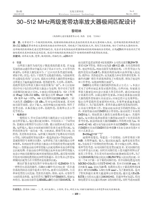
30~512 MHz两级宽带功率放大器极间匹配设计
第6期2021年3月No.6March,20210 引言功率放大器作为现代电子微波系统的最末端,在迅猛发展的移动通信事业中越发凸显了其必不可少、不可替代的重要性。
功率放大器发展至今,广泛应用在各类通信领域,诸如手机、雷达、电台、干扰机等无线通信系统。
当前随着软件无线电技术的广泛运用,系统对功率放大器的带宽和输出功率提出了越来越高的要求,使得超宽带、大功率、高效率、高线性度的功率放大器应用前景极为广阔[1]。
本文以实际项目中用于电台的功率放大器设计为实例,集中讨论了宽带功放极间匹配设计过程。
主要设计指标要求为:(1)工作频段(Freq )为30~512 MHz ;(2)输出功率(Pout )≥80 W ;(3)效率(η)≥35%;(4)双音频率间隔200 kHz 时,三阶互调失真 (IMD3)≤-28 dBc 。
针对这些指标要求,采用两级功放管级联,设计了输入、级间和输出匹配网络,制作了宽带功放,具备高输出功率、高线性度、高效率以及小型化等特点。
1 电路设计一般情况下,针对多级功率放大器的设计方法是使每一级功率管输入、输出都匹配到50Ω,中间再加上一个π型网络,衰减部分射频信号以防止自激,最后级联组成多级放大器。
这样输入、输出分别需要同轴巴伦来完成宽带匹配。
这样的优势是每一级自成一体,方便调试,维修等也方便;同样的,其劣势也很明显,这样极大地限制了电路布局空间的小型化,同时级联时容易自激(一般选择添加π型电阻网络,衰减射频信号来解决自激),这样降低了放大器的输出功率和效率。
本两级宽带功率放大器设计在传统的宽带匹配电路基础上,保留驱动级功率管的输入匹配电路和末级功率管输出匹配电路,在驱动级功率管的输出处和末级功率管的输入处设计两级功放极间匹配所需要的阻抗变换。
通过使用同轴巴伦所用同轴电缆的阻抗和铁氧体磁芯,结合集总元件使这种极间匹配努力在全频带内实现最佳匹配。
横向扩散金属氧化物半导体场效应管(LDMOS )作为一种性价比很高的器件,自20世纪80年代应用以来一直在通信系统的固态功放中起着主导作用。
宽带端网业不匹配更换终端下账方案

宽带端网业不匹配更换终端下账方案各位小伙伴们!今天咱们来聊聊一个可能会让大家有点头疼的事儿——宽带端网业不匹配,然后得更换终端,以及这其中涉及到的下账方案。
别担心,我会用最简单易懂的方式给大家把这事儿说明白,让你看完之后心里门儿清!首先呢,咱得搞清楚啥叫宽带端网业不匹配。
简单来说,就是你家里的宽带设备和网络业务不太搭调,就好比一双大鞋配了一双小袜子,总觉得哪儿不对劲。
这可能会导致网速慢、信号不稳定等各种让人烦躁的问题。
比如说,你办的是高速宽带业务,可家里的终端设备老旧,那这高速的网络就像被堵住的高速公路,车再好也跑不起来啊!那遇到这种情况咋办呢?这时候就需要更换终端啦。
就像给你的网络换一身合适的装备,让它能更好地发挥实力。
更换终端可不是简单地把旧的一扔,新的一装就完事了,这里面还涉及到下账的问题。
咱们这个下账方案啊,就像是给这笔更换终端的费用找个合适的“家”,让它清清楚楚、明明白白地记在该记的地方。
第一步,确认费用明细。
咱得把更换终端的所有费用都列出来,包括新终端的购买费用、安装调试费用等等。
这就好比去超市购物,得把买的每一样东西都记清楚,不然到结账的时候,自己都不知道花了多少钱。
比如说,新的路由器可能要300块,安装费50块,这些都得一项一项地记下来。
第二步,区分费用归属。
有些费用可能是由用户自己承担的,比如你想要升级到更高级的终端设备,那多出来的差价可能就得自己掏腰包啦。
就像你买衣服,想要买名牌的,那肯定得比普通牌子多花点钱。
而有些费用呢,可能是运营商承担的,比如说因为他们之前的配置出了问题,导致不匹配,那这部分更换终端的费用,他们就得担起来。
第三步,下账记录。
这一步就像是把这些费用放到各自的“小抽屉”里。
用户承担的费用,要在用户的账单里清晰地显示出来,让用户知道自己为啥要花这笔钱。
运营商承担的费用呢,也要记在他们相应的账目里,这样到年底算账的时候,也能清楚地知道这钱都花哪儿去了。
为了让大家更好地理解,我给大家举个例子。
宽带匹配网络理论及应用研究

宽带匹配网络理论及应用研究宽带匹配网络理论及应用研究摘要:宽带匹配网络是一种重要的射频(Radio Frequency, RF)和微波(Microwave)电路元件,它在无线通信、雷达、射频模拟电路等领域有着广泛的应用。
本文通过对宽带匹配网络的原理、结构及其在相关应用中的研究进展进行综述,旨在为宽带匹配网络的设计与应用提供一定的参考。
关键词:宽带匹配网络;射频电路;无线通信;微波电路;雷达一、引言在无线通信系统中,信号的传输需要经过由天线、滤波器等组成的射频前端电路。
而射频前端电路的一个核心部分就是宽带匹配网络。
宽带匹配网络可以使射频前端电路与其他电路之间的阻抗进行匹配,从而实现能量传递和信号转换。
因此,宽带匹配网络的性能和设计对于整个射频电路的工作效果至关重要。
二、宽带匹配网络的原理宽带匹配网络的设计是为了实现在宽频带范围内的阻抗匹配,其原理主要基于阻抗变换理论。
在传输线理论中,电磁波在线路中传输时,会遇到特定的阻抗,而当阻抗不匹配时,会产生反射波。
通过在匹配网络中引入阻抗变换元件,可以实现信号的阻抗匹配,减小反射波的发生。
三、宽带匹配网络的结构宽带匹配网络的结构可以分为两种类型:串联结构和并联结构。
串联结构中,利用串联的传输线和变压器等元件来实现阻抗的匹配。
而在并联结构中,通过并联的电容、电感和变压器等元件来实现阻抗的匹配。
两种结构各有利弊,根据具体的应用场景选择合适的结构。
四、宽带匹配网络的应用研究宽带匹配网络在无线通信、雷达、射频模拟电路等领域都有着广泛的应用。
在无线通信系统中,宽带匹配网络可以实现发射端和接收端之间的阻抗匹配,提高信号质量。
在雷达系统中,宽带匹配网络可以实现微波信号的传输和接收,提高雷达系统的性能。
在射频模拟电路中,宽带匹配网络可以实现频率选择性放大和滤波等功能。
五、宽带匹配网络的挑战和展望宽带匹配网络在应用中还存在一些挑战,如:1. 带宽限制:在设计宽带匹配网络时,需要考虑到信号在整个带宽范围内的匹配情况,这对设计的要求提出了更高的要求。
Class-AB宽带功率放大器匹配方法的设计与仿真

Class-AB宽带功率放大器匹配方法的设计与仿真王毅敏;李佳旺【摘要】With the rise of the third communication revolution in the software-defined radio, the broadband RF power amplifier becomes the key part of the software radio transmission system, and has the advantages of wide bandwidth, large dynamic range, small size, long service life and so on. According to the characteristics of software radio and the development trend of current power amplifier, a broadband linear power amplifier with output power of over 25 W and 30-500 MHz working band is designed and developed. By using the coaxial line for broadband matching, and via analyzing the structure model and working characteristics of the push-pull high frequency broadband power amplifier, ADS simulation is done and the design verified. With the appropriate reactance value, the real part of the input-output impedance for the power pipe is made to meet the requirement of the same axis matching. Finally, the coaxial line length, characteristic impedance and the best value of the related components are acquired. After adjustment and optimization, the design reaches the expected indicators. This transformation model has a good prospect of analysis and application in the actual market.%随着软件定义无线电第三次通信革命的兴起,宽带射频功率放大器成为软件无线电发射系统的关键一环,具有频带宽、动态范围大、体积小、寿命长等优点.针对软件无线电的特点及当今功率放大器的发展趋势,设计研制了一款输出功率在25W以上、工作在30~500MHz的宽带线性功率放大器.采用同轴线进行宽带匹配,通过分析推挽式高频宽带功率放大器的结构模型和工作特点,利用ADS仿真验证设计.以合适的电抗值使功率管的输入输出阻抗的实部达到同轴线匹配的要求,最终得到同轴线长度、特性阻抗和相关元器件的最佳取值.经过调整和优化,使设计达到所需指标.这种转换模型在实际市场中有很好的分析应用前景.【期刊名称】《通信技术》【年(卷),期】2018(051)003【总页数】7页(P727-733)【关键词】宽带功率放大器;同轴线匹配;推挽式;ADS【作者】王毅敏;李佳旺【作者单位】哈尔滨工程大学信息与通信工程学院,黑龙江哈尔滨150001;哈尔滨工程大学信息与通信工程学院,黑龙江哈尔滨150001【正文语种】中文【中图分类】TN722.750 引言随着灵活和开放的软件定义无线电第三次通信革命的兴起,越来越多的人开始投入到SDR架构的研究中。
【国家自然科学基金】_宽带匹配_基金支持热词逐年推荐_【万方软件创新助手】_20140730

推荐指数 4 3 2 2 1 1 1 1 1 1 1 1 1 1 1 1 1 1 1 1 1 1 1 1 1 1 1 1 1 1 1 1 1 1 1 1 1
2010年 序号 1 2 3 4 5 6 7 8 9 10 11 12 13 14 15 16 17 18 19 20 21 22 23 24 25 26 27 28 29 30 31 32 33 34 35 36 37 38 39 40 41 42 43 44 45 46 47 48 49 50 51 52
2008年 序号 1 2 3 4 5 6 7 8 9 10 11 12 13 14 15 16 17 18 19 20 21 22 23 24 25 26 27 28 29 30 31 32 33 34 35 36
科研热词 超宽带 集线器 阻抗匹配 阵列 锁存器 自路由 肓信道估计 笼形中馈天线 短截线 相关器 极宽带相位匹配 数值仿真 异质结双极晶体管 小型化 导频 宽带天线 宽带匹配 宽带 多级互连网络 啁啾 同步 双调 切比雪夫多项式 光波长转换 光波长路由 光子晶体光纤 光参量放大 光交换 偶极子天线 交换结构 二项式 二阶统计量 二分频器 th-ppm ppln d触发器
推荐指数 5 4 4 4 2 2 2 1 1 1 1 1 1 1 1 1 1 1 1 1 1 1 1 1 1 1 1 1 1 1 1 1 1 1 1 1 1 1 1 1 1 1 1 1 1 1 1 1 1 1 1 1
2011年 序号 1 2 3 4 5 6 7 8 9 10 11 12 13 14 15 16 17 18 19 20 21 22 23 24 25 26 27 28 29 30 31 32 33 34 35 36 37 38 39 40 41 42 43 44 45 46 47 48 49 50 51 52
宽带匹配网络的优化设计

宽带匹配网络的优化设计杨利容;周芸;龙祖强;刘灿【摘要】宽带匹配网络是通信电子系统必不可少的部分,匹配性能直接影响信号的传输.从数值分析方法出发,采用最优化理论,设计宽带匹配网络.从整个设计过程可以看出,设计过程简单、方便,更易于调试,为以后宽带匹配理论的发展提供了一个崭新的方向.【期刊名称】《衡阳师范学院学报》【年(卷),期】2012(000)006【总页数】3页(P39-41)【关键词】最优化;匹配网络;共轭梯度法【作者】杨利容;周芸;龙祖强;刘灿【作者单位】衡阳师范学院物理与电子信息科学系,湖南衡阳421008【正文语种】中文【中图分类】TN7130 引言带匹配网络是电子信息系统的重要组成部分,匹配的效果直接影响信号的效果。
日前,对宽带匹配网络的具体研究大都是以有源网络为基础,利用电路综合理论进行相应的推导,其过程相当繁琐[1-2],而且在研究的过程中,其研究的网络负载都必须用解析理论的方法进行逼近,得到负载的近似解析表达式,从而使得最终设计的匹配网络无论在参数上还是在性能的精度上都会存在一定的限制。
本文从数值分析方法出发,匹配的网络采用无源网络,利用最优化理论达到设计宽带匹配网络。
这种设计方法从数值分析方法着手,使用软件编程,而不是单一的电路综合理论公式的推导,大大简化了设计工作者的设计过程,并且计算更准确、设计更方便,为以后宽带匹配理论的发展提供了一个崭新的方向。
1 优化算法1.1 共轭梯度法设 H 为n阶对称正定矩阵s(0),s(1),… s(n-1)R(0)是一组 H 共轭方向,任意初始点x(0),令s(0)=-▽f(s(0))由精确一维搜索定出λ0,令其中μ10为待定系数,要使s(0),s(1)是 H 共轭,即要使成立,由此可求得将μ10代入s(1)的表达式中,就可以求出搜索方向s(1),令,x(2)=x (1)+λ1s(1),其中λ1由一维搜索确定。
而μ20和μ21为待定系数,要使 s(2)与 s(0),s (1)分别是 H 共轭,即要(s(2))THs(0)=0,(s(2))THs(1)=0由此可求得类似地可得应用上述方法就可以生成n个关于H共轭的方向s(0),s(1),… s(n-1),但是仔细分析一下上述公式就会发现,在求μij时需要用到f(x)的海赛矩阵H,这是我们所不希望的。
宽带阻抗匹配及高稳定相位中心天线技术研究

宽带阻抗匹配及高稳定相位中心天线技术研究宽带阻抗匹配及高稳定相位中心天线技术研究引言:在当今的信息社会中,无线通信已经成为了人们生活的重要组成部分。
而天线作为无线通信的关键组件之一,其性能优劣对通信质量有着重要影响。
因此,研究宽带阻抗匹配及高稳定相位中心天线技术具有重要的意义。
一、宽带阻抗匹配技术的研究宽带阻抗匹配是指在给定频率范围内,使天线的输入阻抗与发射源或接收器的输出阻抗相匹配,实现最大功率转移的技术。
在实际应用中,由于通信信号的频率范围较宽,单一频率点的匹配往往无法满足通信需求。
因此,我们需要研究宽带阻抗匹配技术来实现多频段通信。
目前,宽带阻抗匹配技术的研究主要集中在两个方面。
首先是开发新型的宽带天线结构,例如:蝶形天线结构、倒F型天线结构等。
这些结构通过调整天线的几何形状和尺寸,可以实现在宽频段内的阻抗匹配。
其次是采用调节元件来实现阻抗匹配,例如:变容器、变电容器等。
这些调节元件通过改变其参数值来调节天线的输入阻抗,从而实现宽带阻抗匹配。
二、高稳定相位中心天线技术的研究相位中心是指天线辐射的主要能量聚集区,也是天线传输和接收信号的主要区域。
因此,保持天线的相位中心的稳定性对于信号传输具有重要意义。
然而,在实际应用中,由于天线的外界环境和物理结构等的影响,天线的相位中心往往会产生变化,从而影响通信质量。
为了解决这个问题,研究人员提出了一些高稳定相位中心天线技术。
其中一种主要方法是通过控制天线的馈电点位置来实现相位中心的稳定,同时减少外界环境的影响。
此外,还可以采用调整天线结构的方式来改善相位中心的稳定性,例如:使用对称结构、均匀辐射结构等。
三、技术应用及前景展望宽带阻抗匹配及高稳定相位中心天线技术的应用十分广泛。
在通信领域,这些技术能够提高通信质量,扩大网络覆盖范围,并支持更多设备的接入。
此外,在雷达和无线电频段的应用中,宽带阻抗匹配和相位中心的稳定性对于信号的传输和接收也具有重要意义。
宽带匹配网络.
(
jω
)|
=
|S21(
jω
)S33
(
jω ) − S23( |S33( jω )|
jω
)S31(
jω
)|
=
|S12 ( |S33 (
jω jω
)| )|
=
S12 ( jω ) S33( jω )
|S22a
(
jω
)|
=
|S22 (
jω )S33(
jω ) − S23( |S33( jω )|
jω
)S32 (
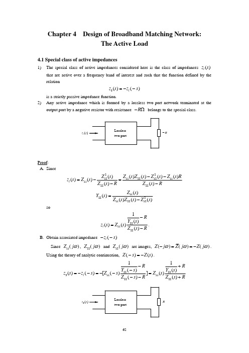
1) General configuration of the negative-resistance amplifiers Our task is to obtain the transducer power-gain from port 1 to port 2 in terms of scattering
Since Z11( jω ) , Z22 ( jω ) and Z12 ( jω ) are images, Z (− jω ) = Z ( jω ) = −Z ( jω ) .
Using the theory of analytic continuation, Z ( − s) = −Z (s) .
65
R2
2 2
Nβ
②
R1
+
1 1①
Vg
−
Nc
③
Na N
Nα
3
zl (s)
②
R1
+
1①
Nc
Vg
−
③
1
①
Nβ ② 3 2
R2
Nd
2
① Nα ② 4 3
二项式与切比雪夫多项式宽带匹配的研究

二项式与切比雪夫多项式宽带匹配的研究宽带匹配,指的是在指定的宽带范围内,实现信号振幅的最佳匹配的算法。
它在众多的通信系统和信号处理系统中都有着重要的应用。
近年来,二项式和切比雪夫多项式宽带滤波器已经得到了广泛的应用,由于它们的低计算复杂度,具有良好的宽带灵敏度,可以在滤波器的宽带中实现最佳的信号匹配。
二项式宽带滤波器是一种常见的数字滤波器,它由多个干涉器阶段组成,阶段数可以任意改变,以满足不同的业务需求。
根据网络合成原理,每个模块的输入信号具有相同的频率,但可能具有不同的幅度和相位。
二项式宽带滤波器的特点是,可以有效地去除高频噪声,以保证信号的稳定性。
切比雪夫多项式宽带匹配技术,是一种基于多项式拟合的宽带匹配方法。
它通过多项式拟合实现信号振幅的估计,从而实现宽带优化。
切比雪夫多项式宽带匹配,与二项式宽带滤波器有着许多共同之处,例如,它们都可以有效地抑制外部信号。
与二项式宽带滤波器的不同之处在于,计算复杂度更低,因此,可以更好地实现宽带匹配和降低噪声。
二项式与切比雪夫多项式宽带匹配技术的应用,可以显著提高信号处理系统的性能,例如,在无线信号接收系统中,可以有效减少外部干扰信号的影响,提高无线信号的稳定性。
此外,它还可用于不同类型的数字信号处理系统,例如宽带滤波器,滤波器拓扑结构等,可以提高系统的效率。
研究人员已经开展了一系列的研究,主要集中在二项式和切比雪夫多项式宽带滤波器的性能分析上。
例如,研究人员比较了两种滤波器的稳定性,以及它们在宽带优化中的表现。
此外,研究人员还比较了两种滤波器的计算复杂度,并研究了它们对噪声的抑制作用。
综上所述,二项式与切比雪夫多项式宽带匹配技术逐渐得到越来越多的应用,由于它们的优势,它们可以有效满足不同类型的宽带优化需求。
继续研究它们的特性,可以进一步提升信号处理系统的性能,为宽带应用技术的发展做出更大的贡献。
短波天线宽带匹配网络设计的若干研究

短波天线宽带匹配网络设计的若干研究邱宇【摘要】随着我国科技的不断进步,人们对于短波天线宽带的使用方式有了更高的要求。
因此笔者讨论了短波天线宽带匹配网络设计,并结合讨论的结果给出了优化设计的目标函数,在数值分析的基础上采用一种改进型的遗传算法。
【期刊名称】《黑龙江科技信息》【年(卷),期】2016(000)016【总页数】1页(P95-95)【关键词】短波天线;宽带;网络设计【作者】邱宇【作者单位】国家新闻出版广电总局2021台,黑龙江齐齐哈尔 161000【正文语种】中文随着社会的不断发展,短波天线宽带匹配网络的设计问题一直受到人们的重视,因此笔者在统计学的理论上研究出来一种快速的、适应性强的、遗传算法。
这种遗传算法对于短波天线宽带匹配网络优化设计比较适用。
笔者在这里提出了一种集总加载天线,同时对集总加载天线匹配网络的设计方案进行了优化,集总加载天线中天线是一个鞭状天线,采取在距离馈电点处接入一个复阻抗的方式,这个复阻抗采用的是并联的形式。
对于天线匹配网络采用的是T型,或者是π型,但是这里所使用的支路采用的连接方式不再是并联,而是串并联形式。
笔者以π型网络做为例子进行探讨,其中串联支路顾名思义使用的是串联的方式,并联支路使用的是并联的形式[1]。
它包括的匹配网络结构的形式非常之多,这就意味着只需要将这些元件的值设置为零,或者是设置成无穷大。
在这里所需要解决的问题是属于合理的选择加载位置、以及加载值,同时设计一个宽带匹配网络,从而使得天线的频率达到规定的范围。
从理论上,可以清楚的了解到集总加载形式的天线为单极天线,对单极天线采用的计算其电流分布的方法是矩量法。
对于函数采用的都是分段正弦函数,那么对于细圆柱天线的抗拒阵元素的公式中,可以看出当频率确定的时候,广义的阻抗矩阵是不会发生改变的,这就意味着广义的阻抗矩阵只和基函数,以及全函数使用的形式有关。
当加载阻抗在不断变化的时候,只有广义电压矩阵在随着加载阻抗的变化而变化,这就意味着只需要在广义的阻抗矩阵的基础上做出一点点的变动就即可[2]。
二项式与切比雪夫多项式宽带匹配的研究

二项式与切比雪夫多项式宽带匹配的研究
二项式与切比雪夫多项式宽带匹配是指使用二项式或切比雪夫多项式来调谐电路的频率响应,使得电路在某一宽带内具有较好的匹配效果。
二项式是指只包含一次幂项和常数项的多项式,形式为ax+b。
切比雪夫多项式是指含有
常数项和一次以上幂项的多项式,形式为a0+a1x+a2x^2+...+anx^n。
在宽带匹配中,使用二项式或切比雪夫多项式可以更精确地控制电路的频率响应,使得电
路在某一宽带内具有较好的匹配效果。
这一研究领域主要应用于电路设计和电子工程领域。
在研究二项式与切比雪夫多项式宽带匹配时,需要考虑多种因素,包括:
➢电路的频率响应特性:电路的频率响应特性决定了电路对信号的响应情况,是宽带匹配的重要因素。
➢电路元件的特性:电路中使用的元件,如电感、电容等,都会对电路的频率响应产生影响。
因此,在设计电路时需要考虑元件的特性。
➢电路的负载特性:电路的负载特性也会影响电路的频率响应。
因此,在设计电路时需要考虑负载特性。
研究二项式与切比雪夫多项式宽式宽带匹配的研究主要通过数学模型和实验测量来进行。
通常,在研究二项式宽带匹配时,会使用Smith Chart来分析电路的频率响应特性,计算
出最优的匹配参数。
在研究切比雪夫多项式宽带匹配时,会使用数学模型来分析电路的频
率响应特性,计算出最优的匹配参数。
研究二项式与切比雪夫多项式宽带匹配具有重要的理论意义和实际应用价值。
天津市东丽广电宽带路由器设置简要说明(图解版)

天津市东丽广电宽带路由器设置简要说明用户使用路由器,首先将入户网线(上连网线)与路由器WAN口连接,再用连接线将用户PC机上的网卡与路由器LAN口连接。
对应的指示灯亮表示链路连接正常。
一、路由器设置:进入路由器管理页面,首先对WAN口进行设置。
1、不要在路由器中设置虚拟拨号的用户名和密码。
本网络不支持路由器拨号上网。
2、要在路由器的WAN口设置中选择“静态IP”模式,并在对应输入框中设置用户账号分配的ip地址、子网掩码、网关和DNS。
如图一所示:(图一)输入完成后点“确定”按钮。
由于绝大部分路由器对LAN口默认都启用了DHCP功能,所以不用对LAN口作设置。
路由器中的其他设置也不需要更改。
(DHCP地址池地址段不能为192.168.1.×,改成192.168.0.X)二、PC机设置:用户PC机不需要在本地连接里面设置IP地址等参数,网卡与路由器LAN口正常连接后,路由器会为PC机自动分配一个IP地址。
用户只需要直接打开IE浏览器,输入网址:192.168.1.100 如图二所示:(图二)IE浏览器将打开东丽广电宽带用户认证网页,如图三所示:(图三)在对应输入框中输入用户账号与密码,点击“登陆”按钮,登陆成功后,PC机便可正常上网。
如一台路由器连接了多台PC机或无线移动终端,那只需要一台PC机或移动终端进行网页登陆后,其他PC机和移动终端便可不用登陆直接上网。
特别说明:1.用户账号通过网页登陆后如30分钟内与外网没有产生数据流量,那计费网关会自动注销(下线)此账号。
用户再上网需重新登陆账号。
2.如用户账号通过网页方式登陆,并且账号计费策略为计时收费类型,用户在终止网络使用时需通过网页:192.168.1.100进行账号注销操作。
3.如用户移动终端不能连接网络而与路由器通过网线连接的机器能够上网,那是路由器的无线设置与移动终端设置不匹配造成,需用户自行调试。
文案编辑词条B 添加义项?文案,原指放书的桌子,后来指在桌子上写字的人。
基于NSGA-Ⅱ的宽带天线匹配网络设计

图 1中二 端 E网络 散射矩 阵 为 . l
;[ ] =
输 入端 口反 射系数 为
应 用 于频率 范 围为 1 50MH 0— 9 z的宽带 天线 匹配
s
= 素
网络的设计. 仿真结果表明, 利用 N G . 算法优 S AI I
第3 3卷
第 2期
大
连
交
通 大
学
学 报
Vo _ No 2 l33 . AD . 01 r2 2
21 0 2年 4月
I T0 V IY J URNAL OF D I J A0 NG UNI ERS T O AL AN
文 章 编 号 :6 3 99 (0 2 0 — 10 0 17 — 5 0 2 1 )2 0 0 — 4
于2 0世纪 9 0年 代初 期 提 出 , 是 基 于 P rt 它 ae o最
式,={ 表天阻对性抗 中 丢 示线抗特阻
性 阻抗 的反射 系数 .
.参 数反 映二 端 口网络 的端 口入射 波 和反射 s 波 之 间
界 为
优 概念 的多 目标 遗 传 算 法 . e D b于 20 02年 在 N . S
1 宽 带天 线 匹配 网络
图 1 示二 端 口网络 为待设 计 的天线 匹配 网 所
络, Z 表示 匹配 网络所 接天线 的 阻抗 .
中取 得 了一定 成 果 , 中经 常遇 到 多 目标 函数 的 其
优化 问题 . 上面 提 到 的 多 目标 优 化 方 法 主要 是 但
将 多 目标 优化 问题 转变 为单 目标 优 化 问题 . 采用 单 目标优 化 的方法 求解 , 次只 能得 到一个 解 , 每 需
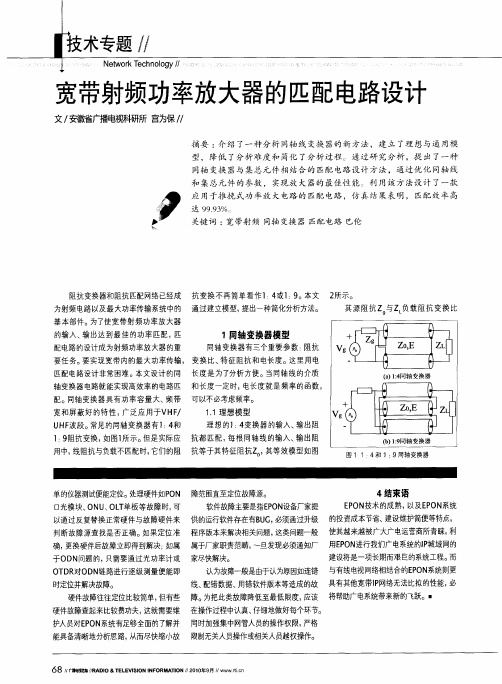
宽带射频功率放大器的匹配电路设计
68/ 播 信 川A l & E E IO F R AIN/0  ̄ ,/ w c / E 麓 R D TLV INN O M T / 1 -9 / w i 广暾 o S I O 209 w nn
一 无线技术 / /
,
Newo kT c n o y/ t r e h olg /
=
当反射 系数为零时, 功率可以无反
射的传输, 这时阻抗实现完Hale Waihona Puke 匹配。 分子为零 , 即:
r: = :0
( /0( +0 z z :0z g )z )
1 : 4 () 1
由公式 ( ) 反射系数 为零可以等效 为 但是实际同轴线的特征阻抗是有一定规 2,
=
图2 和公式 ( ) 1 表明 : 变换 器的阻
其源 阻抗Z 与Z 负载 阻抗 变换 比
的输入、 输出达到最佳的功率匹配, 匹
配电 的设计成为射频功率放大器 的重 路
1 同轴变换器模型
同轴变换器有三个重要参数: 阻抗
要任务。 要实现宽带内的最大功率传输 变换 比、 特征阻抗和 电长度 。 这里用电
分析 方便。 当同轴线的介质 匹配电路设计非常困难。本文设计 的同 长度是为了 电长度就是频率 的函数 轴变换器 电 路就能实现高效率 的电路匹 和长度一定时, 配 。 轴 变换器具有功率容量大、 同 频带 可以不必考虑频率。 宽和屏蔽好 的特 性, 广泛应用于VH / F
率变化 的, 所以采用同轴变换器和集 总
元件联合实现宽带匹配的方式。
抗变换比等于输入阻抗与输出阻抗之比。
z. i一磊’ =0
— 一
同轴变换器的输入阻抗等于同轴线的输 入阻抗并联 , 出阻抗等于 同轴线的输 输 出阻抗串联。 12通用模型 . 由 于特征阻抗是实数, 而源阻抗与 负 载阻抗一般都是复数 , 所以, 就不能简
- 1、下载文档前请自行甄别文档内容的完整性,平台不提供额外的编辑、内容补充、找答案等附加服务。
- 2、"仅部分预览"的文档,不可在线预览部分如存在完整性等问题,可反馈申请退款(可完整预览的文档不适用该条件!)。
- 3、如文档侵犯您的权益,请联系客服反馈,我们会尽快为您处理(人工客服工作时间:9:00-18:30)。
(12)
Since b = coC, the bandwidth / c is given by
/c
.,2
T
1/2
=
g
2TTC
a
-(a2 + 1 -302)
(13)
In the following theory it is assumed that the X/4 line is a quarter wavelength at all frequencies, that is, it is an ideal X/4 line. Referring again to Fig. 1 and assuming that each load is a parallel CR lowpass, such as network shown in Fig. 2a, then eqn. 3 gives
|p o l)
(1-IPol)
(14)
where b = coc. From eqn. 5 we get
Y2
l — IPOI
P
n
2
-
go+g
n (,,
+
Y2
)
+
where So is the v.s.w.r. when b is zero, so
IV
+
V +ft2[1
I'
g2 + b'\
Y2
Yi
a = (l+(32)S0
Eqn. 13 expresses the bandwidth in terms of the coefficients, a and (3, but a and j3 are themselves related, in terms of |pol, by eqn. 9. For a given |pol there are two solutions for a and j3 depending on whether a > (1 + /32) or +j3 2 )then a = Now 1 + lPol
Consider the circuit shown in Fig. 1. If a passive load admittance YL is connected to the end of a A/4 transmission line of characteristic admittance Yo, it is easily shown that the input admittance of the line is
Similarly, ii
(15)
g2+b2
(7)
(16) It can be shown that a Chebyshev-type frequency response is obtained when a < ( l 4-132) and a Butterworth response is obtained when a > (1 + ft2). As the derivation of eqn. 13 assumed a Chebyshev response, a can be eliminated by substituting eqn. 16 into it, which gives
ห้องสมุดไป่ตู้Yl
" YL
(1)
Paper T32 2 M, first received 16th October 1978 and in revised form 16th January 1979 Mr. Aitchison is, and Mr. Chapman was formerly, with the Electronics Department, Chelsea College, Pulton Place, London SW6 5PR, England Mr. Chapman is now with the Royal Signals and Radar Establishment, St Andrew's Road, Malvern, Worcs., England
|2 _
+ ft2^2 U 2 + 2 ( 1 - | 3 2 ) -
go - Yin go + Yit
2
= 0 (11)
The third term of eqn. 11 is zero, hence (5) b2 =
8
so, clearly, by varying the value of Yo the degree of match of the loads to the source can be changed. The values of g0 and Yo for minimum mismatch and maximum bandwidth for different types of load and circuit configuration are analysed in the next Section.
If yL = g + jb then
(2)
One of the most common problems encountered in electronic circuit design is that of providing a broadband impedance match to a resistive source of a complex load impedance. Conventional impedance-matching techniques at low frequencies involve ladder networks of lumped inductances and capacitances, while at microwave frequencies, resort is frequently made to distributed elements in the form of lengths of open-circuit or short-circuit transmission lines which approximate to lumped inductances and capacitances. Usually matching networks are designed to have a specific frequency response in the passband1 such as the Chebyshev or Butterworth responses. Occasionally techniques are used which simply reduce the mismatch without intending to achieve a particular frequency response ? A technique which has been used with considerable success in increasing the gain-bandwidth product of parametric amplifiers3'4 and Impatt amplifiers5 and increasing the tuning range of Gunn oscillators6'7 is active reactance compensation. Active reactance compensation takes advantage of the impedance-inverting property of a quarter-wavelength transmission line. By connecting two identical devices together with such a line the inverted impedance of one device compensates the impedance of the other by reducing the total circuit reactances. So far the technique has only been applied to the problem of broadbanding active loads, that is devices with a negative-resistance characteristic. The object of this paper is to consider its application to either increasing the bandwidth for a given mismatch or reducing the mismatch over a given band for passive loads, that is loads with a positiveresistance characteristic.
Fig. 1 Basic shunt compensation circuit 43 0308-6976/79/020043 + OS $01-50/0
MICROWA VES, OPTICS AND ACOUSTICS, MARCH 1979, Vol. 3, No. 2
at the expense of not cancelling the susceptances. The reflection coefficient of the circuit shown in Fig. 1 is given by
