探索者三维MEP建模设计软件说明书
探索者 功能简介

功能简介TSSD的功能共分为四列菜单:平面、构件、计算、工具。
一、平面主要功能是画结构平面布置图,其中有梁、柱、墙、基础的平面布置,大型集成类工具板设计,与其它结构类软件图形的接口。
平面布置图不但可以绘制,更可以方便的编辑修改。
每种构件均配有复制、移动、修改、删除的功能。
这些功能不是简单的CAD 功能,而是再深入开发的专项功能。
与其它结构类软件图形的接口主要有天正建筑(天正7以下的所有版本)、PKPM系列施工图、广厦CAD,转化完成的图形可以使用TSSD的所有工具再编辑。
二、构件主要功能是结构中常用构件的详图绘制,有梁、柱、墙、楼梯、雨蓬阳台、承台、基础。
只要输入几个参数,就可以轻松的完成各详图节点的绘制。
三、计算主要功能是结构中常用构件的边算边画,既可以整个工程系统进行计算,也可以分别计算。
可以计算的构件主要有板、梁、柱、基础、承台、楼梯等等,这些计算均可以实现透明计算过程,生成WORD计算书。
四、工具主要是结构绘图中常用的图面标注编辑工具,包括:尺寸、文字、钢筋、表格、符号、比例变换、参照助手、图形比对等等共有200多个工具,襄括了所有在图中可能遇到的问题解决方案,可以大幅度提高工程师的绘图速度。
功能优势一、专业化的多比例绘图功能,满足用户不同绘图习惯方式在使用CAD绘制施工图绘制过程中,比例的设置和变化一直是设计人员很疼痛的工作,一张图纸中经常需要绘制不同比例的图形以满足布图的需求,一直以来,设计人员多使用插入图块的方式来解决此类问题,随着CAD技术上的不断成熟,近年来有了外部引用等方式,但目前现行的各种绘图手段都不能完全满足设计人员正真实现在一张图中实时实现多比例绘图,更不能满足很多设计人员所希望的真正1:1绘制施工图的需求。
探索者TSSD软件以设计人员的需求为出发点,想设计人员所想,为用户提供了功能强大,操作使用方便的多比例绘图方式,能按照设计人员不同的绘图需求定制符合完全自己绘图习惯的比例设置模式,不论是固定出图比例方式中的不同绘图比例的绘图方法,还是动态调整出图比例随时实现1:1方式绘图都可以方便地实现。
《RevitMEP教程》课件

电气系统
掌握在RevitMEP中设计和 布线电气系统的技巧,包 括照明、插座和配电系统。
管道系统
了解在RevitMEP中建模和 优化管道系统,包括给水、 排水和消防系统。
模型构建技巧
分享一些实用的建模技巧,帮助您提高建模效率和质量,包括族编辑、参数 化建模和模型协作。
பைடு நூலகம்
实例演示
1
示例项目1
通过一个实际建筑项目的演示,展示RevitMEP在实践中的应用和优势。
界面功能
详细解析RevitMEP的界面布局和各个功能区域,帮助您快速上手并提高工作 效率。
系统设置
介绍如何进行RevitMEP的系统设置,包括单位设置、协作设置等,确保项目 文件的准确性和一致性。
三大模块详解
机械系统
学习如何在RevitMEP中创 建和编辑机械系统,包括 空调、通风和制冷系统。
2
示例项目2
进一步深入了解RevitMEP的高级功能和复杂项目的应用示例。
3
实用技巧
分享一些实用的技巧和技术,帮助您更好地利用RevitMEP完成各种工作任务。
《RevitMEP教程》PPT课 件
通过本课件,您将深入了解RevitMEP的各个方面,掌握软件的使用技巧和模 型构建方法,并通过实例演示加深理解。
RevitMEP教程概述
本节将介绍RevitMEP教程的内容和目的,以及学习本教程的前提要求。
软件介绍
了解RevitMEP的基本信息,包括功能和适用领域,以及它与其他建模软件的比较优势。
探索者结构工程CAD系列软件详细说明

探索者结构工程CAD系列软件详细说明探索者结构工程CAD系列软件是一套专业的建筑结构工程设计软件,可用于建筑结构设计、钢结构设计、预制构件设计、预应力混凝土结构设计等多个领域的设计与检验。
本文将从软件的主要功能模块、操作流程和优点等方面进行详细说明。
一、软件的主要功能模块1.建模模块该模块可用于创建3D结构模型,并自动生成2D施工图和材料清单。
该模块支持多种材料的建模,如钢筋、混凝土等,可根据设计要求进行建模。
此外,该模块还可通过导入外部文件进行建模,如DXF、DWG、IGES、STEP等。
建模后可对模型进行参数化操作,如调整尺寸、角度等。
2.荷载模块该模块可用于确定结构所受荷载大小和方向。
该模块支持建筑结构荷载、地震荷载、风荷载等多种荷载类型,并可进行合成计算。
此外,该模块可根据不同荷载情况进行动力分析和稳定性分析等。
3.设计模块该模块可用于设计结构的各种构件,如梁、柱、板、墙等。
该模块支持多种材料的设计,如钢、混凝土、预应力混凝土等。
此外,该模块还支持编制设计荷载组合、极限状态下的受力状态判断以及构件截面尺寸计算等。
4.分析模块该模块可用于进行结构分析,如弹性分析、框架位移法、有限元分析等。
该模块可对结构所受荷载进行计算和合成,并计算结构的受力状态和变形情况。
此外,该模块还支持动力分析和热力分析等。
5.检验模块该模块可用于检验结构的受力状态和变形情况是否符合规范和设计要求。
该模块可对结构的安全性、可靠性和经济性进行评价,并生成相应的检验报告。
此外,该模块还支持极限状态下的承载能力评价、疲劳寿命评价等。
二、操作流程1.建模:首先进行建模,创建3D模型。
2.荷载:确定结构所受荷载大小和方向。
3.设计:设计结构各种构件,如梁、柱、板、墙等。
4.分析:对结构进行弹性分析、框架位移法、有限元分析等。
5.检验:进行结构的受力状态和变形情况的检验和评价。
三、优点1.多种材料支持:软件支持多种材料的建模和设计,如钢、混凝土、预应力混凝土等。
AutoCADMEP建筑工程设计入门指南
AutoCADMEP建筑工程设计入门指南AutoCAD MEP(Mechanical, Electrical, Plumbing)是一种专注于建筑工程设计的软件工具,能够帮助设计师创建、编辑和分析各种建筑设备和系统。
本篇文章将提供一份AutoCAD MEP建筑工程设计入门指南,帮助读者快速了解和使用该软件。
第一章:介绍AutoCAD MEPAutoCAD MEP是由Autodesk开发的一款专用软件,旨在帮助建筑工程师和设计师进行机械、电气和管道系统的建模和设计。
它结合了AutoCAD和Revit的功能,能够提供更高效的工作流程和更精确的设计结果。
第二章:界面和工作空间在本节中,将介绍AutoCAD MEP的界面和工作空间。
包括主工作区域、工具栏、菜单栏、命令行和属性编辑器等。
读者将了解如何自定义工作空间以适应自己的需求,以及如何使用各种工具和命令。
第三章:建筑系统建模本章将详细介绍如何在AutoCAD MEP中进行建筑系统建模。
从创建建筑模型到添加各种建筑组件和设备,包括空调系统、电气设备和管道系统等。
读者将了解如何使用不同的工具和功能进行建模,并学会如何调整参数以实现最佳效果。
第四章:系统分析和优化建筑系统的分析和优化是一个重要的环节,可以帮助设计师评估系统的性能,提高能源效率和减少资源浪费。
在本章中,将介绍AutoCAD MEP中的分析工具,包括能源分析、运行模拟和液体流动模拟等。
读者将学会如何使用这些工具来评估和优化建筑系统的性能。
第五章:协作和文档管理在多人合作的建筑项目中,协作和文档管理是至关重要的。
AutoCAD MEP提供了各种协作和文档管理工具,帮助设计师协调工作、共享设计文件和进行版本控制。
本章将介绍如何使用这些工具,并提供一些建议和技巧以提高协作效率。
第六章:实际案例分析为了更好地理解AutoCAD MEP的应用,本章将提供一些实际案例分析。
通过具体的项目示例,读者将了解如何使用AutoCAD MEP解决实际的建筑工程设计问题,并学会从理论应用到实际项目中的技巧和经验。
探索者软件 协同设计流程
探索者软件协同设计流程一、啥是探索者软件呀。
探索者软件可是个超酷的软件呢!对于咱们这些搞设计的小伙伴来说,它就像是一个超级得力的助手。
这个软件涵盖了好多功能,从结构设计到一些细节的优化,它都能搞定。
而且哦,它的协同设计功能特别棒,能让好多小伙伴一起在这个软件里干活,就像大家一起搭积木一样有趣。
二、协同设计的前期准备。
1. 团队组建。
咱们要先把参与协同设计的小伙伴们都找齐呀。
这就像是组建一个超级英雄团队,有擅长结构计算的,有精通绘图的,还有对各种规范特别了解的小伙伴。
大家来自不同的专长领域,聚在一起就为了把这个设计项目做得超级完美。
2. 软件熟悉。
在开始协同设计之前呢,大家都得对探索者软件有一定的了解。
不能有人还对软件一知半解就开始干活呀,那可就乱套了。
我们可以一起开个小会,互相分享一下自己对软件不同功能的认识,就像分享小秘密一样。
比如说,有人知道怎么快速绘制梁配筋图,有人知道怎么调整结构模型的参数最方便,把这些小技巧都分享出来,大家就都能更好地在软件里操作啦。
三、协同设计中的流程。
1. 项目框架搭建。
先由团队里对整体架构把握比较好的小伙伴来搭建项目的框架。
这就像是盖房子先打地基和搭框架一样重要。
这个框架要把整个项目的大致结构确定下来,比如有多少层楼,每层楼的功能分区大概是怎样的。
在探索者软件里,这个小伙伴就要把基本的结构模型先建立起来,设置好一些重要的参数。
其他小伙伴看到这个框架之后,就知道自己的工作要怎么开展啦。
2. 分工协作。
然后呢,就根据大家的专长来分工。
绘图厉害的小伙伴就负责把框架里的一些草图绘制得更加精细,计算大神就负责对结构进行各种计算,确保安全性和合理性。
大家在自己的小领域里努力工作,但是又要时刻和其他小伙伴保持沟通哦。
就像在一个大厨房里,每个厨师负责一道菜,但是大家也要互相交流,确保整个宴席的菜品搭配完美。
3. 实时沟通。
在协同设计过程中,沟通真的是太重要啦!我们可以利用探索者软件自带的一些沟通工具,比如说在软件里可以对某个设计元素进行批注,告诉其他小伙伴自己的想法。
Revit MEP 快速入门

Revit MEPRevit MEP快速入门2008 年 4 月版权所有©2008 Autodesk, Inc.。
保留所有权利。
除非获得 Autodesk, Inc. 的批准,否则本出版物或其任何部分,均不允许任何人因任何目的、以任何形式、采用任何方法予以复制。
本出版物中包含的某些材料经过版权所有者的允许可以进行复制。
免责声明本出版物和其中包含的信息由 AUTODESK, INC. 按照其实际状态(以“AS-IS”方式)提供。
AUTODESK, INC. 对这些材料不作任何明确或隐含的担保,包括但不仅限于对适销性和针对特定用途的适用性的担保。
商标T以下是 Autodesk, Inc. 在美国和/或其他国家/地区的注册商标或商标:AutoCAD、Autodesk、Autodesk(徽标)、ViewCube、SteeringWheels 和 Revit。
所有其他品牌名称、产品名称或商标均属于其各自的持有者。
© 2003 American Society of Heating, Refrigerating and Air-Conditioning Engineers, Inc. () used by permission.IES <Virtual Environment>, IES <VE> Copyright© 2007 by Integrated Environmental Solutions Limited目录第 1 章快速入门 . . . . . . . . . . . . . . . . . . . . . . . . . . . . . . . 1简介 . . . . . . . . . . . . . . . . . . . . . . . . . . . . . . . . . . . . . 1用户界面 . . . . . . . . . . . . . . . . . . . . . . . . . . . . . . . . . . . 2菜单栏和工具栏 . . . . . . . . . . . . . . . . . . . . . . . . . . . . 2设计栏 . . . . . . . . . . . . . . . . . . . . . . . . . . . . . . . . . 3选项栏 . . . . . . . . . . . . . . . . . . . . . . . . . . . . . . . . . 3项目浏览器 . . . . . . . . . . . . . . . . . . . . . . . . . . . . . . 4状态栏 . . . . . . . . . . . . . . . . . . . . . . . . . . . . . . . . . 5视图控制栏 . . . . . . . . . . . . . . . . . . . . . . . . . . . . . . 5系统浏览器 . . . . . . . . . . . . . . . . . . . . . . . . . . . . . . 5系统概念 . . . . . . . . . . . . . . . . . . . . . . . . . . . . . . . . . . . 6建筑信息模型 . . . . . . . . . . . . . . . . . . . . . . . . . . . . . 6构件族 . . . . . . . . . . . . . . . . . . . . . . . . . . . . . . . . . 7样板 . . . . . . . . . . . . . . . . . . . . . . . . . . . . . . . . . . 7视图规程 . . . . . . . . . . . . . . . . . . . . . . . . . . . . . 7使用 Tab 键进行选择 . . . . . . . . . . . . . . . . . . . . . . . . . . 8捕捉 . . . . . . . . . . . . . . . . . . . . . . . . . . . . . . . . . . 8构件控制柄 . . . . . . . . . . . . . . . . . . . . . . . . . . . . . . 9图形控制柄 . . . . . . . . . . . . . . . . . . . . . . . . . . . . . . 10机械系统 . . . . . . . . . . . . . . . . . . . . . . . . . . . . . . . . . . 11准备机械设计 . . . . . . . . . . . . . . . . . . . . . . . . . . . . . 11iii负荷分析 . . . . . . . . . . . . . . . . . . . . . . . . . . . . 12机械设置 . . . . . . . . . . . . . . . . . . . . . . . . . . . . . . . 12创建空气调节系统 . . . . . . . . . . . . . . . . . . . . . . . . . . 13放置空气调节系统构件 . . . . . . . . . . . . . . . . . . . . . 14为空气调节系统创建管网 . . . . . . . . . . . . . . . . . . . . 14修改空气调节系统 . . . . . . . . . . . . . . . . . . . . . . . 15管道、卫浴和消防系统 . . . . . . . . . . . . . . . . . . . . . . . . 15放置构件 . . . . . . . . . . . . . . . . . . . . . . . . . . . . 15管道布局 . . . . . . . . . . . . . . . . . . . . . . . . . . . . 15管道行为 . . . . . . . . . . . . . . . . . . . . . . . . . . . . 16电气系统 . . . . . . . . . . . . . . . . . . . . . . . . . . . . . . . . . . 16准备电气设计 . . . . . . . . . . . . . . . . . . . . . . . . . . . . . 16创建电气系统 . . . . . . . . . . . . . . . . . . . . . . . . . . . . . 16完成机械和电气设计 . . . . . . . . . . . . . . . . . . . . . . . . . 22 iv | 目录1快速入门欢迎使用 Revit® MEP 2009。
Revit MEP 2011用户指南说明书

Revit MEP 2011 User's GuideApril 2010©2010 Autodesk, Inc. All Rights Reserved. Except as otherwise permitted by Autodesk, Inc., this publication, or parts thereof, may not be reproduced in any form, by any method, for any purpose.Certain materials included in this publication are reprinted with the permission of the copyright holder.DisclaimerTHIS PUBLICATION AND THE INFORMATION CONTAINED HEREIN IS MADE AVAILABLE BY AUTODESK, INC. "AS IS." AUTODESK, INC. DISCLAIMS ALL WARRANTIES, EITHER EXPRESS OR IMPLIED, INCLUDING BUT NOT LIMITED TO ANY IMPLIED WARRANTIES OF MERCHANTABILITY OR FITNESS FOR A PARTICULAR PURPOSE REGARDING THESE MATERIALS.TrademarksThe following are registered trademarks or trademarks of Autodesk, Inc., and/or its subsidiaries and/or affiliates in the USA and other countries: 3DEC (design/logo), 3December, , 3ds Max, Algor, Alias, Alias (swirl design/logo), AliasStudio, Alias|Wavefront (design/logo), ATC, AUGI, AutoCAD, AutoCAD Learning Assistance, AutoCAD LT, AutoCAD Simulator, AutoCAD SQL Extension, AutoCAD SQL Interface, Autodesk, Autodesk Envision, Autodesk Intent, Autodesk Inventor, Autodesk Map, Autodesk MapGuide, Autodesk Streamline, AutoLISP, AutoSnap, AutoSketch, AutoTrack, Backburner, Backdraft, Built with ObjectARX (logo), Burn, Buzzsaw, CAiCE, Civil 3D, Cleaner, Cleaner Central, ClearScale, Colour Warper, Combustion, Communication Specification, Constructware, Content Explorer, Dancing Baby (image), DesignCenter, Design Doctor, Designer's Toolkit, DesignKids, DesignProf, DesignServer, DesignStudio, Design Web Format, Discreet, DWF, DWG, DWG (logo), DWG Extreme, DWG TrueConvert, DWG TrueView, DXF, Ecotect, Exposure, Extending the Design Team, Face Robot, FBX, Fempro, Fire, Flame, Flare, Flint, FMDesktop, Freewheel, GDX Driver, Green Building Studio, Heads-up Design, Heidi, HumanIK, IDEA Server, i-drop, ImageModeler, iMOUT, Incinerator, Inferno, Inventor, Inventor LT, Kaydara, Kaydara (design/logo), Kynapse, Kynogon, LandXplorer, Lustre, MatchMover, Maya, Mechanical Desktop, Moldflow, Moonbox, MotionBuilder, Movimento, MPA, MPA (design/logo), Moldflow Plastics Advisers, MPI, Moldflow Plastics Insight, MPX, MPX (design/logo), Moldflow Plastics Xpert, Mudbox, Multi-Master Editing, Navisworks, ObjectARX, ObjectDBX, Open Reality, Opticore, Opticore Opus, Pipeplus, PolarSnap, PortfolioWall, Powered with Autodesk Technology, Productstream, ProjectPoint, ProMaterials, RasterDWG, RealDWG, Real-time Roto, Recognize, Render Queue, Retimer,Reveal, Revit, Showcase, ShowMotion, SketchBook, Smoke, Softimage, Softimage|XSI (design/logo), Sparks, SteeringWheels, Stitcher, Stone, StudioTools, ToolClip, Topobase, Toxik, TrustedDWG, ViewCube, Visual, Visual LISP, Volo, Vtour, Wire, Wiretap, WiretapCentral, XSI, and XSI (design/logo).ContentsChapter 1What’s New? . . . . . . . . . . . . . . . . . . . . . . . . . . . . . . . . . . . . . . . . . . . 1 New in Revit MEP 2011 . . . . . . . . . . . . . . . . . . . . . . . . . . . . . . . . . . . . . . . . . . . 1Introduction to Revit . . . . . . . . . . . . . . . . . . . . . . . . . . . . . . . . . . 9Chapter 2Building Information Modeling . . . . . . . . . . . . . . . . . . . . . . . . . . . . . . . . 11 What Is Revit MEP? . . . . . . . . . . . . . . . . . . . . . . . . . . . . . . . . . . . . . . . . . . . . 11What Is Meant by Parametric? . . . . . . . . . . . . . . . . . . . . . . . . . . . . . . . . . . . . . . . 11How Does Revit MEP Keep Things Updated? . . . . . . . . . . . . . . . . . . . . . . . . . . . . . . . 12Understanding Revit Terms . . . . . . . . . . . . . . . . . . . . . . . . . . . . . . . . . . . . . . . . 12Element Behavior in a Parametric Modeler . . . . . . . . . . . . . . . . . . . . . . . . . . . . . . . . 14Element Properties . . . . . . . . . . . . . . . . . . . . . . . . . . . . . . . . . . . . . . . . . . . . . 15Chapter 3Licensing . . . . . . . . . . . . . . . . . . . . . . . . . . . . . . . . . . . . . . . . . . . . 17 Licensing Overview . . . . . . . . . . . . . . . . . . . . . . . . . . . . . . . . . . . . . . . . . . . . 17Standalone Licensing . . . . . . . . . . . . . . . . . . . . . . . . . . . . . . . . . . . . . . . . . . . 17Licensing Extension . . . . . . . . . . . . . . . . . . . . . . . . . . . . . . . . . . . . . . . . . . . . 18License Transferring . . . . . . . . . . . . . . . . . . . . . . . . . . . . . . . . . . . . . . . . . . . . 18License Borrowing . . . . . . . . . . . . . . . . . . . . . . . . . . . . . . . . . . . . . . . . . . . . . 18Chapter 4User Interface . . . . . . . . . . . . . . . . . . . . . . . . . . . . . . . . . . . . . . . . . . 21 Ribbon . . . . . . . . . . . . . . . . . . . . . . . . . . . . . . . . . . . . . . . . . . . . . . . . . . . 21 Customizing the Ribbon . . . . . . . . . . . . . . . . . . . . . . . . . . . . . . . . . . . . . . . 22 Application Menu . . . . . . . . . . . . . . . . . . . . . . . . . . . . . . . . . . . . . . . . . . . . . 24Quick Access Toolbar . . . . . . . . . . . . . . . . . . . . . . . . . . . . . . . . . . . . . . . . . . . 25Tooltips . . . . . . . . . . . . . . . . . . . . . . . . . . . . . . . . . . . . . . . . . . . . . . . . . . . 26Keytips . . . . . . . . . . . . . . . . . . . . . . . . . . . . . . . . . . . . . . . . . . . . . . . . . . . 27Project Browser . . . . . . . . . . . . . . . . . . . . . . . . . . . . . . . . . . . . . . . . . . . . . . . 28 Using the Project Browser . . . . . . . . . . . . . . . . . . . . . . . . . . . . . . . . . . . . . . 28 Drawing Area . . . . . . . . . . . . . . . . . . . . . . . . . . . . . . . . . . . . . . . . . . . . . . . . 32iiiStatus Bar . . . . . . . . . . . . . . . . . . . . . . . . . . . . . . . . . . . . . . . . . . . . . . . . . . 33Options Bar . . . . . . . . . . . . . . . . . . . . . . . . . . . . . . . . . . . . . . . . . . . . . . . . 34Properties Palette . . . . . . . . . . . . . . . . . . . . . . . . . . . . . . . . . . . . . . . . . . . . . . 34 Modifying Instance Properties . . . . . . . . . . . . . . . . . . . . . . . . . . . . . . . . . . . . 36Modifying Type Properties . . . . . . . . . . . . . . . . . . . . . . . . . . . . . . . . . . . . . . 37Creating a New Family Type in a Project . . . . . . . . . . . . . . . . . . . . . . . . . . . . . . 38Previewing Family Types . . . . . . . . . . . . . . . . . . . . . . . . . . . . . . . . . . . . . . 38 View Control Bar . . . . . . . . . . . . . . . . . . . . . . . . . . . . . . . . . . . . . . . . . . . . . . 39Recent Files . . . . . . . . . . . . . . . . . . . . . . . . . . . . . . . . . . . . . . . . . . . . . . . . . 40InfoCenter . . . . . . . . . . . . . . . . . . . . . . . . . . . . . . . . . . . . . . . . . . . . . . . . . 40 Overview of InfoCenter . . . . . . . . . . . . . . . . . . . . . . . . . . . . . . . . . . . . . . . 40Search For Information . . . . . . . . . . . . . . . . . . . . . . . . . . . . . . . . . . . . . . . 41Receive Product Updates and Announcements . . . . . . . . . . . . . . . . . . . . . . . . . . . 42Save and Access Favorite Topics . . . . . . . . . . . . . . . . . . . . . . . . . . . . . . . . . . . 43Specify InfoCenter Settings . . . . . . . . . . . . . . . . . . . . . . . . . . . . . . . . . . . . . 44Search Topics in Help . . . . . . . . . . . . . . . . . . . . . . . . . . . . . . . . . . . . . . . . 47 Autodesk® Seek . . . . . . . . . . . . . . . . . . . . . . . . . . . . . . . . . . . . . . . . . . . . . . 47 Searching for Content with Autodesk Seek . . . . . . . . . . . . . . . . . . . . . . . . . . . . . 49 Online Help . . . . . . . . . . . . . . . . . . . . . . . . . . . . . . . . . . . . . . . . . . . . . . . . 52Start a Project . . . . . . . . . . . . . . . . . . . . . . . . . . . . . . . . . . . . . 53Chapter 5C reating a Project . . . . . . . . . . . . . . . . . . . . . . . . . . . . . . . . . . . . . . . 55 Creating a Project Using Default Settings . . . . . . . . . . . . . . . . . . . . . . . . . . . . . . . . . 55Creating a Project Using a Template . . . . . . . . . . . . . . . . . . . . . . . . . . . . . . . . . . . . 55Before You Begin a Project . . . . . . . . . . . . . . . . . . . . . . . . . . . . . . . . . . . . . . . . . 56Chapter 6Using Information from Other Sources . . . . . . . . . . . . . . . . . . . . . . . . . . . . 57 Import/Link Overview . . . . . . . . . . . . . . . . . . . . . . . . . . . . . . . . . . . . . . . . . . . 57 Suitability of Imported Geometry . . . . . . . . . . . . . . . . . . . . . . . . . . . . . . . . . . 57Implications of Importing vs. Linking for Xrefs . . . . . . . . . . . . . . . . . . . . . . . . . . 58 Importing or Linking CAD Formats . . . . . . . . . . . . . . . . . . . . . . . . . . . . . . . . . . . . 58 Importing or Linking CAD Files Using the Import CAD and Link CAD Tools . . . . . . . . . . . 59Importing CAD Files Using i-drop . . . . . . . . . . . . . . . . . . . . . . . . . . . . . . . . . . 59Importing Files from SketchUp . . . . . . . . . . . . . . . . . . . . . . . . . . . . . . . . . . . 60Importing ACIS Objects . . . . . . . . . . . . . . . . . . . . . . . . . . . . . . . . . . . . . . . 62Import and Link Options for CAD Formats and Revit Models . . . . . . . . . . . . . . . . . . . 63Setting Scaling for Imported DWG or DXF Files . . . . . . . . . . . . . . . . . . . . . . . . . . 65Setting Line Weights for Imported DWG or DXF Files . . . . . . . . . . . . . . . . . . . . . . . 65Mapping AutoCAD SHX Fonts to TrueType Fonts . . . . . . . . . . . . . . . . . . . . . . . . . 65Setting Constraint Parameters for Imported Geometry . . . . . . . . . . . . . . . . . . . . . . . 66Moving a View-Specific Import to the Foreground or Background . . . . . . . . . . . . . . . . . 66 Importing Images . . . . . . . . . . . . . . . . . . . . . . . . . . . . . . . . . . . . . . . . . . . . . 66 Modifying Imported Images . . . . . . . . . . . . . . . . . . . . . . . . . . . . . . . . . . . . . 67Deleting Raster Images . . . . . . . . . . . . . . . . . . . . . . . . . . . . . . . . . . . . . . . . 67 Importing Building Components . . . . . . . . . . . . . . . . . . . . . . . . . . . . . . . . . . . . . 68 Building Component ADSK Files . . . . . . . . . . . . . . . . . . . . . . . . . . . . . . . . . . 68Working with Building Components . . . . . . . . . . . . . . . . . . . . . . . . . . . . . . . . 68Tips for Working with Building Components . . . . . . . . . . . . . . . . . . . . . . . . . . . . 69Building Component Workflow . . . . . . . . . . . . . . . . . . . . . . . . . . . . . . . . . . . 69 Opening Industry Foundation Class (IFC) Files . . . . . . . . . . . . . . . . . . . . . . . . . . . . . . 70 Selecting a Template for IFC Files . . . . . . . . . . . . . . . . . . . . . . . . . . . . . . . . . . 71Loading an IFC Class Mapping File . . . . . . . . . . . . . . . . . . . . . . . . . . . . . . . . . 71Overriding Categories and Subcategories for IFC Objects . . . . . . . . . . . . . . . . . . . . . . 71 Linking AutoCAD Files to a Revit Project . . . . . . . . . . . . . . . . . . . . . . . . . . . . . . . . . 71 How Linking to AutoCAD Files Works . . . . . . . . . . . . . . . . . . . . . . . . . . . . . . . 72Linking to an AutoCAD File . . . . . . . . . . . . . . . . . . . . . . . . . . . . . . . . . . . . . 72 iv | ContentsLocation of the Linked File . . . . . . . . . . . . . . . . . . . . . . . . . . . . . . . . . . . . . 73 Linking DWF Markup Files . . . . . . . . . . . . . . . . . . . . . . . . . . . . . . . . . . . . . . . . 74 Modifying DWF Markups Created in Design Review . . . . . . . . . . . . . . . . . . . . . . . . 74 Exploding Imported Geometry . . . . . . . . . . . . . . . . . . . . . . . . . . . . . . . . . . . . . . 75Managing Layers in Linked and Imported Files . . . . . . . . . . . . . . . . . . . . . . . . . . . . . . 75 Querying Objects in Layers . . . . . . . . . . . . . . . . . . . . . . . . . . . . . . . . . . . . . 75Hiding and Deleting Layers . . . . . . . . . . . . . . . . . . . . . . . . . . . . . . . . . . . . . 76Changing the Graphic Display of Layers . . . . . . . . . . . . . . . . . . . . . . . . . . . . . . 78 Importing a Loads Analysis from a gbXML File . . . . . . . . . . . . . . . . . . . . . . . . . . . . . . 79Troubleshooting Problems with Linked Files . . . . . . . . . . . . . . . . . . . . . . . . . . . . . . . 80 Changes in the DWG File Are Not Reflected in the Revit Project . . . . . . . . . . . . . . . . . . 80Changes to the Layer Color and Line Style Do Not Display in the Revit Project . . . . . . . . . . 80Layers in the DWG File Do Not Display in the Revit Project . . . . . . . . . . . . . . . . . . . . 80File Operations (Open, Save, Synchronize) Are Blocked or Slow . . . . . . . . . . . . . . . . . . 81Chapter 7Opening Revit Files . . . . . . . . . . . . . . . . . . . . . . . . . . . . . . . . . . . . . . . 83 Opening a Revit Project File . . . . . . . . . . . . . . . . . . . . . . . . . . . . . . . . . . . . . . . . 83Opening Families and Training Files . . . . . . . . . . . . . . . . . . . . . . . . . . . . . . . . . . . 84Opening Files from the Conceptual Design Environment . . . . . . . . . . . . . . . . . . . . . . . . 84Opening Files from the Web Library . . . . . . . . . . . . . . . . . . . . . . . . . . . . . . . . . . . 84Opening Revit Files from Windows Explorer . . . . . . . . . . . . . . . . . . . . . . . . . . . . . . . 85Chapter 8Saving Revit Files . . . . . . . . . . . . . . . . . . . . . . . . . . . . . . . . . . . . . . . . 87 Saving a File with a Different Name or Location . . . . . . . . . . . . . . . . . . . . . . . . . . . . . 87Save Options . . . . . . . . . . . . . . . . . . . . . . . . . . . . . . . . . . . . . . . . . . . . . . . . 88Setting Save Reminders . . . . . . . . . . . . . . . . . . . . . . . . . . . . . . . . . . . . . . . . . . 88Backup and Journal Files . . . . . . . . . . . . . . . . . . . . . . . . . . . . . . . . . . . . . . . . . . 89 Specifying the Number of Backup Files . . . . . . . . . . . . . . . . . . . . . . . . . . . . . . . 89Backup Files for Network Saves . . . . . . . . . . . . . . . . . . . . . . . . . . . . . . . . . . . 89Journal Files . . . . . . . . . . . . . . . . . . . . . . . . . . . . . . . . . . . . . . . . . . . . . 90 Preliminary Design . . . . . . . . . . . . . . . . . . . . . . . . . . . . . . . . . . 91Chapter 9Levels and Grids . . . . . . . . . . . . . . . . . . . . . . . . . . . . . . . . . . . . . . . . 93 Levels . . . . . . . . . . . . . . . . . . . . . . . . . . . . . . . . . . . . . . . . . . . . . . . . . . . . 93 Adding Levels . . . . . . . . . . . . . . . . . . . . . . . . . . . . . . . . . . . . . . . . . . . . 94Modifying Levels . . . . . . . . . . . . . . . . . . . . . . . . . . . . . . . . . . . . . . . . . . . 95Level Properties . . . . . . . . . . . . . . . . . . . . . . . . . . . . . . . . . . . . . . . . . . . 96 Grids . . . . . . . . . . . . . . . . . . . . . . . . . . . . . . . . . . . . . . . . . . . . . . . . . . . . 98 Adding Grids . . . . . . . . . . . . . . . . . . . . . . . . . . . . . . . . . . . . . . . . . . . . . 99Modifying Grids . . . . . . . . . . . . . . . . . . . . . . . . . . . . . . . . . . . . . . . . . . . 99Grid Properties . . . . . . . . . . . . . . . . . . . . . . . . . . . . . . . . . . . . . . . . . . . 105Chapter 10Project Location and Orientation . . . . . . . . . . . . . . . . . . . . . . . . . . . . . . . 107 Specifying the Project Location . . . . . . . . . . . . . . . . . . . . . . . . . . . . . . . . . . . . . 107 Troubleshooting Location Dialog Issues . . . . . . . . . . . . . . . . . . . . . . . . . . . . . . 111 Rotating a View to True North . . . . . . . . . . . . . . . . . . . . . . . . . . . . . . . . . . . . . . 112Rotating Project North . . . . . . . . . . . . . . . . . . . . . . . . . . . . . . . . . . . . . . . . . . 113Chapter 11C onceptual Design Environment . . . . . . . . . . . . . . . . . . . . . . . . . . . . . . . 115 Conceptual Design Environment Overview . . . . . . . . . . . . . . . . . . . . . . . . . . . . . . . 116 Exploring Conceptual Designs . . . . . . . . . . . . . . . . . . . . . . . . . . . . . . . . . . . 116Early Conceptual Study Models . . . . . . . . . . . . . . . . . . . . . . . . . . . . . . . . . . 116Integrated Study Models . . . . . . . . . . . . . . . . . . . . . . . . . . . . . . . . . . . . . . 117Intelligent Sub-Components . . . . . . . . . . . . . . . . . . . . . . . . . . . . . . . . . . . . 117 Conceptual Design Environment Interface . . . . . . . . . . . . . . . . . . . . . . . . . . . . . . . 117Contents | vConceptual Massing Family Creation . . . . . . . . . . . . . . . . . . . . . . . . . . . . . . . 118Switching between Conceptual Design and Project Environments . . . . . . . . . . . . . . . . 118Template Files for the Conceptual Design Environment . . . . . . . . . . . . . . . . . . . . . 120 Drawing in the Conceptual Design Environment . . . . . . . . . . . . . . . . . . . . . . . . . . . . 121 Drawing Overview . . . . . . . . . . . . . . . . . . . . . . . . . . . . . . . . . . . . . . . . . 1213D Snapping . . . . . . . . . . . . . . . . . . . . . . . . . . . . . . . . . . . . . . . . . . . . 1213D Aligning . . . . . . . . . . . . . . . . . . . . . . . . . . . . . . . . . . . . . . . . . . . . . 122Conceptual Design Model Line Instance Properties . . . . . . . . . . . . . . . . . . . . . . . . 1243D Work Planes . . . . . . . . . . . . . . . . . . . . . . . . . . . . . . . . . . . . . . . . . . . 1253D Levels . . . . . . . . . . . . . . . . . . . . . . . . . . . . . . . . . . . . . . . . . . . . . . 1283D Reference Planes . . . . . . . . . . . . . . . . . . . . . . . . . . . . . . . . . . . . . . . . 131Reference Points . . . . . . . . . . . . . . . . . . . . . . . . . . . . . . . . . . . . . . . . . . 132 X-Ray Mode . . . . . . . . . . . . . . . . . . . . . . . . . . . . . . . . . . . . . . . . . . . . . . . . 143 Accessing X-Ray Mode . . . . . . . . . . . . . . . . . . . . . . . . . . . . . . . . . . . . . . . 143Display of Elements in X-Ray Mode . . . . . . . . . . . . . . . . . . . . . . . . . . . . . . . . 143Manipulating Forms in X-Ray Mode . . . . . . . . . . . . . . . . . . . . . . . . . . . . . . . . 144 Profiles . . . . . . . . . . . . . . . . . . . . . . . . . . . . . . . . . . . . . . . . . . . . . . . . . . 145 Locked Profiles . . . . . . . . . . . . . . . . . . . . . . . . . . . . . . . . . . . . . . . . . . . 145Locking and Unlocking Profiles . . . . . . . . . . . . . . . . . . . . . . . . . . . . . . . . . . 146 Forms . . . . . . . . . . . . . . . . . . . . . . . . . . . . . . . . . . . . . . . . . . . . . . . . . . . 147 Solid and Void Forms . . . . . . . . . . . . . . . . . . . . . . . . . . . . . . . . . . . . . . . . 147Creating Solid Forms . . . . . . . . . . . . . . . . . . . . . . . . . . . . . . . . . . . . . . . . 148Creating Void Forms . . . . . . . . . . . . . . . . . . . . . . . . . . . . . . . . . . . . . . . . 150Accessing Create Form Tool . . . . . . . . . . . . . . . . . . . . . . . . . . . . . . . . . . . . 150Unconstrained and Referenced-Based Forms . . . . . . . . . . . . . . . . . . . . . . . . . . . 151Selecting Forms . . . . . . . . . . . . . . . . . . . . . . . . . . . . . . . . . . . . . . . . . . . 152Form Types . . . . . . . . . . . . . . . . . . . . . . . . . . . . . . . . . . . . . . . . . . . . . 153Modifying Forms . . . . . . . . . . . . . . . . . . . . . . . . . . . . . . . . . . . . . . . . . . 160Rehosting Forms . . . . . . . . . . . . . . . . . . . . . . . . . . . . . . . . . . . . . . . . . . 164Dimensioning Forms . . . . . . . . . . . . . . . . . . . . . . . . . . . . . . . . . . . . . . . . 164Referencing Imported Geometry . . . . . . . . . . . . . . . . . . . . . . . . . . . . . . . . . . 166Conceptual Design Environment Model Instance Properties . . . . . . . . . . . . . . . . . . . 167Manipulating Forms . . . . . . . . . . . . . . . . . . . . . . . . . . . . . . . . . . . . . . . . 167Manipulating Joined Forms . . . . . . . . . . . . . . . . . . . . . . . . . . . . . . . . . . . . 168 Rationalizing Surfaces . . . . . . . . . . . . . . . . . . . . . . . . . . . . . . . . . . . . . . . . . . 170 Dividing a Surface with UV Grids . . . . . . . . . . . . . . . . . . . . . . . . . . . . . . . . . 170Understanding UV Grids . . . . . . . . . . . . . . . . . . . . . . . . . . . . . . . . . . . . . . 170Enabling and Disabling UV Grids . . . . . . . . . . . . . . . . . . . . . . . . . . . . . . . . . 171Modifying the Spacing of UV Grids on Divided Surfaces . . . . . . . . . . . . . . . . . . . . . 172Adjusting UV Grids with the Face Manager . . . . . . . . . . . . . . . . . . . . . . . . . . . . 172Dividing a Surface by Intersection . . . . . . . . . . . . . . . . . . . . . . . . . . . . . . . . . 176Patterning Surfaces . . . . . . . . . . . . . . . . . . . . . . . . . . . . . . . . . . . . . . . . . 177Editing the Patterned Surface . . . . . . . . . . . . . . . . . . . . . . . . . . . . . . . . . . . 180Pattern Component Families . . . . . . . . . . . . . . . . . . . . . . . . . . . . . . . . . . . . 181Surface Representation . . . . . . . . . . . . . . . . . . . . . . . . . . . . . . . . . . . . . . . 190Pattern Element Properties . . . . . . . . . . . . . . . . . . . . . . . . . . . . . . . . . . . . . 191 Conceptual Design Environment Glossary . . . . . . . . . . . . . . . . . . . . . . . . . . . . . . . 194Chapter 12Revit MEP Essentials . . . . . . . . . . . . . . . . . . . . . . . . . . . . . . . . . . . . . . 197 Connect Into . . . . . . . . . . . . . . . . . . . . . . . . . . . . . . . . . . . . . . . . . . . . . . . 197System Browser . . . . . . . . . . . . . . . . . . . . . . . . . . . . . . . . . . . . . . . . . . . . . . 197 Column Settings . . . . . . . . . . . . . . . . . . . . . . . . . . . . . . . . . . . . . . . . . . 198 Selecting Column Headings . . . . . . . . . . . . . . . . . . . . . . . . . . . . . . . . . 198 System Inspector . . . . . . . . . . . . . . . . . . . . . . . . . . . . . . . . . . . . . . . . . . . . . 199 Using the System Inspector . . . . . . . . . . . . . . . . . . . . . . . . . . . . . . . . . . . . 199 Spaces . . . . . . . . . . . . . . . . . . . . . . . . . . . . . . . . . . . . . . . . . . . . . . . . . . . 199 Place Spaces Automatically . . . . . . . . . . . . . . . . . . . . . . . . . . . . . . . . . . . . . 201Space Creation During Project Upgrade . . . . . . . . . . . . . . . . . . . . . . . . . . . . . . 201Volume Computations . . . . . . . . . . . . . . . . . . . . . . . . . . . . . . . . . . . . . . . 202 vi | ContentsPlacing Spaces . . . . . . . . . . . . . . . . . . . . . . . . . . . . . . . . . . . . . . . . . . . 203 Placing Spaces Up to the Level Above . . . . . . . . . . . . . . . . . . . . . . . . . . . . 204Placing Spaces up to the Ceiling . . . . . . . . . . . . . . . . . . . . . . . . . . . . . . . 206Placing Spaces for Plenums . . . . . . . . . . . . . . . . . . . . . . . . . . . . . . . . . 210Placing Spaces Up to the Roof . . . . . . . . . . . . . . . . . . . . . . . . . . . . . . . . 213Placing Spaces for Complex Vertical Areas . . . . . . . . . . . . . . . . . . . . . . . . . . 216Placing Spaces for Shafts and Chases . . . . . . . . . . . . . . . . . . . . . . . . . . . . 221Adding Space Tags . . . . . . . . . . . . . . . . . . . . . . . . . . . . . . . . . . . . . . 223 Accounting for the Volume of Cavities, Shafts, and Chases . . . . . . . . . . . . . . . . . . . . 224 Resolving the Volume of Cavities, Shafts, and Chases . . . . . . . . . . . . . . . . . . . 225 Modifying Spaces . . . . . . . . . . . . . . . . . . . . . . . . . . . . . . . . . . . . . . . . . . 227 Redefining the Vertical Extent of a Space . . . . . . . . . . . . . . . . . . . . . . . . . . 227Dividing Spaces . . . . . . . . . . . . . . . . . . . . . . . . . . . . . . . . . . . . . . . . 234Combining Spaces . . . . . . . . . . . . . . . . . . . . . . . . . . . . . . . . . . . . . . 234Moving Spaces . . . . . . . . . . . . . . . . . . . . . . . . . . . . . . . . . . . . . . . . 234Removing Spaces . . . . . . . . . . . . . . . . . . . . . . . . . . . . . . . . . . . . . . . 235Modifying Space Properties . . . . . . . . . . . . . . . . . . . . . . . . . . . . . . . . . 236 Viewing and Selecting Spaces . . . . . . . . . . . . . . . . . . . . . . . . . . . . . . . . . . . 237 Make Spaces Visible . . . . . . . . . . . . . . . . . . . . . . . . . . . . . . . . . . . . . 237Spaces in Floor Plan and Section Views . . . . . . . . . . . . . . . . . . . . . . . . . . . 237Spaces in Elevation or 3D Views . . . . . . . . . . . . . . . . . . . . . . . . . . . . . . . 237Spaces in the System Browser . . . . . . . . . . . . . . . . . . . . . . . . . . . . . . . . 237Spaces Visibility Troubleshooting . . . . . . . . . . . . . . . . . . . . . . . . . . . . . . 238 Creating a Space Schedule . . . . . . . . . . . . . . . . . . . . . . . . . . . . . . . . . . . . . 238 Viewing Unplaced Spaces in a Space Schedule . . . . . . . . . . . . . . . . . . . . . . . 239Hiding Unplaced Spaces in a Space Schedule . . . . . . . . . . . . . . . . . . . . . . . . 239 Applying a Color Scheme to Spaces . . . . . . . . . . . . . . . . . . . . . . . . . . . . . . . . 240Verifying Spaces . . . . . . . . . . . . . . . . . . . . . . . . . . . . . . . . . . . . . . . . . . 240Using Space Separation Lines . . . . . . . . . . . . . . . . . . . . . . . . . . . . . . . . . . . 240 Drawing Space Separation Lines . . . . . . . . . . . . . . . . . . . . . . . . . . . . . . . 241Controlling the Visibility of Space Separation Lines . . . . . . . . . . . . . . . . . . . . 243Removing Space Separator Lines . . . . . . . . . . . . . . . . . . . . . . . . . . . . . . . 243 Working with Spaces in a Linked Model . . . . . . . . . . . . . . . . . . . . . . . . . . . . . . 243 Specifying the Linked Model as Room-Bounding . . . . . . . . . . . . . . . . . . . . . . 244 Working with Phases and Spaces . . . . . . . . . . . . . . . . . . . . . . . . . . . . . . . . . . 244Space Properties . . . . . . . . . . . . . . . . . . . . . . . . . . . . . . . . . . . . . . . . . . 245 Default Building Type and Space Type Parameters . . . . . . . . . . . . . . . . . . . . . 248Specifying Schedule Settings . . . . . . . . . . . . . . . . . . . . . . . . . . . . . . . . . 249Construction Type Parameters . . . . . . . . . . . . . . . . . . . . . . . . . . . . . . . . 250People Loads Parameters . . . . . . . . . . . . . . . . . . . . . . . . . . . . . . . . . . . 250Electrical Loads Parameters . . . . . . . . . . . . . . . . . . . . . . . . . . . . . . . . . . 251 Embedded Schedules . . . . . . . . . . . . . . . . . . . . . . . . . . . . . . . . . . . . . . . . . . . 251 Creating an Embedded Schedule . . . . . . . . . . . . . . . . . . . . . . . . . . . . . . . . . . 251 Chapter 13Duct Systems . . . . . . . . . . . . . . . . . . . . . . . . . . . . . . . . . . . . . . . . . 253 Working with Mechanical Components . . . . . . . . . . . . . . . . . . . . . . . . . . . . . . . . . 253 Break-into Components . . . . . . . . . . . . . . . . . . . . . . . . . . . . . . . . . . . . . . 253Duct . . . . . . . . . . . . . . . . . . . . . . . . . . . . . . . . . . . . . . . . . . . . . . . . . 254 Duct Options Bar Settings . . . . . . . . . . . . . . . . . . . . . . . . . . . . . . . . . . 254Duct Placement Tools . . . . . . . . . . . . . . . . . . . . . . . . . . . . . . . . . . . . 254Justification Settings . . . . . . . . . . . . . . . . . . . . . . . . . . . . . . . . . . . . . 255Drawing Duct In a Plan View . . . . . . . . . . . . . . . . . . . . . . . . . . . . . . . . 255Drawing Ductwork In an Elevation or Section View . . . . . . . . . . . . . . . . . . . . 256Specifying Default Fittings for a Duct Type . . . . . . . . . . . . . . . . . . . . . . . . . 265Connecting Ducts to an Existing System . . . . . . . . . . . . . . . . . . . . . . . . . . 265Duct Controls . . . . . . . . . . . . . . . . . . . . . . . . . . . . . . . . . . . . . . . . 266 Flexible Ducts . . . . . . . . . . . . . . . . . . . . . . . . . . . . . . . . . . . . . . . . . . . . 267 Flexible Duct Options Bar Settings . . . . . . . . . . . . . . . . . . . . . . . . . . . . . . 267Flex Duct Placement Tools . . . . . . . . . . . . . . . . . . . . . . . . . . . . . . . . . . 267Contents | vii。
3D建模软件的使用教程
3D建模软件的使用教程随着科技的发展,3D建模软件在许多行业中的应用越来越广泛。
无论是建筑设计、工业设计还是动画制作,3D建模软件都起到了至关重要的作用。
本文将为大家介绍一种常用的3D建模软件,并提供详细的使用教程。
首先,我们介绍的是Autodesk公司开发的AutoCAD软件,它是一款功能强大,被广泛使用的3D建模软件。
下面将分为以下几个部分,依次介绍AutoCAD软件的安装、界面操作、绘图工具和常用功能。
一、安装AutoCAD软件在开始使用AutoCAD软件之前,我们需要先将其安装到电脑上。
首先从Autodesk官方网站下载安装文件,然后双击运行文件,按照提示进行安装。
安装完成后,在桌面上会出现AutoCAD的快捷方式。
二、界面操作启动AutoCAD软件后,会进入主界面。
先让我们熟悉一下主界面的各个元素:1. 菜单栏:包含了各种功能和操作选项;2. 工具栏:提供常用的快捷操作;3. 绘图区:用于绘制和编辑图形的区域;4. 命令窗口:用于输入命令和查看系统信息;5. 属性编辑器:用于修改对象的属性;6. 已打开文件列表:显示当前已打开的文件。
三、绘图工具AutoCAD提供了多种绘制工具,可以满足各种绘图需求。
下面介绍几个常用的绘图工具及其使用方法:1. 线段工具:通过点击画布上的两个点,可以绘制一条直线;2. 圆工具:通过点击圆心和半径点,可以绘制一个圆;3. 矩形工具:通过点击矩形的对角点,可以绘制一个矩形;4. 多边形工具:通过指定多边形的边数和中心点,可以绘制一个规则的多边形;5. 视图工具:可以调整视图的缩放比例、旋转角度和观察角度。
四、常用功能除了基本的绘图工具,AutoCAD还提供了一些常用的功能,方便用户进行更多的操作和修改。
以下是几个常用功能的介绍:1. 编辑功能:可以对已绘制的图形进行修改,如移动、旋转、缩放等;2. 属性设置:可以修改图形的线型、颜色、填充等属性;3. 图层管理:可以将不同的图形分别放在不同的图层中,并进行管理和控制;4. 三维建模:AutoCAD不仅支持2D绘图,还可进行3D建模和渲染,给出更加逼真的效果;5. 打印和导出:可以将绘制的图形打印或导出为图片或其他文件格式,方便与他人共享。
“探索者”快速入门课程包-新版 2.简单结构的组装

(一)认识STPViewer软件
1.简介
STP是一种通用的3D文件格式,可以在几乎所有的3D设计软件中打 开。STP Viewer是一款小体量的、针对STP格式文件的看图软件,可 以打开和观看STP格式3D文件,方便参照3D图组装。
2.安装STPViewer
提示:STP文件存储路径中不能有中文字符或特殊符号,否则软件 无法读取。某些操作系统桌面也不识别。
打开文件后,首先看到的是3D线框图
Dynamic Panning
Color
Shade
4.在“STP-class1”文件夹中找到“quadrilateral.stp”文件,双击打开。这 是前面做过的四边形的3D文件。
5.STPViewer还有一个“隐藏零件”的功能
选中一个“机械手40”,然后可以看到在软件界面左侧零件树列表中, 对应的零件名也被选中了。 在该零件名上点击右键,选择“hide”。“机械手40”即可隐藏,里面的轴 套就能看到了。
(二)训练项目三:平板车的组装
1.通过对一个平板车的组装,能够继续深化训练以下技能:
2.组装内容
组装一个驱动轮模块
3.器材
直流电机、直流马达输出头、直流电机支架、轮胎、螺柱15、联轴器、 螺丝F325、螺丝F310、螺丝F2510H、螺母
4.组装过程
(1)安装直流电机 支架安装:常见装法完成后的效果图。使用螺丝:F325
输出头安装:完成效果图如下。安装于粉色端,中心需安装F2510H
选择一块7×11孔的平板,利用2个8mm的螺丝固定一个驱动轮模块:
在平板对称位置重复上一步骤,再固定一个驱动轮模块
最后在平板的边缘中心位置选择合适的空位将万向轮模块组装完成:
Revit MEP 电气设计教程说明书

Everything Electrical for Revit MEP®Don Sarmiento – ARUP, Senior CAD Technician [San Francisco, CA]Geoff Gunn, PE – ARUP, Senior Engineer [Boston, MA]MP6679The title of this class speaks for itself. You will learn everything you need to know about Revit MEP software, focusing entirely on the electrical side. Topics will include managing your project template; creating 2D annotation symbols and electrical families; creating more efficient diagrams; using filters for your electrical systems; and laying out fixtures. We’ll also look at devices and equipment, circuiting, and scheduling. We will cover techniques for achieving better coordination between disciplines (mechanical, electrical, and plumbing) and making the most out of Revit MEP software and we will discuss some best practices. We will also share with you an actual project that implemented items discussed during this lecture.Learning ObjectivesAt the end of this class, you will be able to:•Learn different techniques for efficient diagrams and discover why it's better in Revit software, forget linked CAD files•Learn how to create efficient 2D annotations and electrical families and discover that it's not always about how they look, but how they work•Using filters for better workflow. You'll be surprise what filters can do for you•Learn about coordination practices between electrical and mechanical, plumbing, and lighting, and discuss how we should we handle thisAbout the SpeakersDon Sarmiento is a Senior CAD Technician at Arup, a multidiscipline engineering firm based in San Francisco, California, which has over 90 offices throughout the world. He has over 17 years of experience in electrical drafting, using AutoCAD® software, AutoCAD MEP® software, and Revit MEP® software. He also worked as an electrical designer for over 5 years. Currently he is involved in the implementation of Building Information Modeling (BIM) using Revit MEP® software for the Electrical Group within Arup’s America’s region. He also provides internal training of Revit software and often presents at internal and regional meetings.**********************Geoff Gunn is a Senior Electrical Engineer based in the Boston, Massachusetts office of Arup, a multidiscipline engineering firm which has over 90 offices throughout the world. He has experience in electrical engineering for a wide range of project types from University labs, healthcare facilities, and data centers. Geoff has detailed hands-on experience producing electrical engineering designs using AutoCAD® software, AutoCAD MEP® software, and Revit MEP® software. Geoff is always looking for new ways to introduce Building Information Modeling techniques into the electrical engineering process in order to simplify drawing production, improve accuracy, and enhance communication with Architect's and facility Owners.*******************Techniques for Efficient Diagrams in RevitLet’s be honest. When we all transitioned from AutoCAD to Revit, the last thing that we probably did in Revit, was our diagrams and our details. Maybe because we were intimidated by change, and just not familiar with the commands in Revit. But working in a 2D environment in Revit is actually really easy and efficient, and it is just a matter of getting used to it.Here are some tips on how to create efficient diagrams in Revit.1. Create all your contentIf it’s a symbol, create it! Consider using masking region in building your symbols. We’ll discuss more about this later.2. Determine your sheet limitsThis should be the first thing you ever do when drafting. You don’t want to keep drafting then realize you’ve drawn over your sheets as you finish. Check your border, and measure.3. Create a grid guide in your drafting view or floor plan that matches your sheet limitsCreating a grid allows you work quicker, more efficient, and prevents you from “eye balling”, when laying out your detail lines. This will also allow you to create a more presentable diagram. Creating a family would make this more efficient.4. Pin the grid guideDetail item family5.Click on the “Select Pinned Elements” iconBy pinning the grid, then clicking on the “Select Pinned Elements” icon, this will allow you to hover over the grid, without selecting the grid. After these simple steps, you should be able to start on your diagram.6.Create different line styles for each distribution branchThis allows for your too easily follow the connections.7.Utilize the grid guide lines when drafting your detail lines8.Consider using masking region, instead of splitting when lines intersect as belowHere are the steps in using masking region:a.Create a masking region.b.Highlight the details lines that you do not want masked, then “bring to front”.The image below is the result after masking.9.Lock generic annotations (symbols) onto the detail linesThis allows the symbols to move with the detail lines as it moves.10.Turn off the grid guide before you printTip: If your diagram is large enough to continue onto another sheet, you can also create your diagram in a floor plan so you could generate dependent views.Figure 1.1 below is one of the most complex diagrams that I have ever worked on, created in a floor plan view, duplicated into 3 dependent views (Figure 1.2). Remember, all lines runs across continuously from sheet to sheet like the levels, and feeders. Lines are masked between sheets using masking region.Figure 1.1Figure 1.2Efficient 2D Symbols and Modeled familiesCreating content could be lots of fun. Once you get into it, you will think of different ways to be creative with your content, and try to make them as efficient as possible. Here are some things to consider when building content.1. For 2D Generic Annotation Familiesa.Make good use of masking region.b. Create all the Labels and Text as needed. If it needs to change, use a Label and set it asan instance. If not, use a Text. Name the Label to be understandable.c. Visibility. If there are multiple Symbols in your Family, make sure to set the visibilitycorrectly with a Yes/No Parameter.Masking regionMasks the detail line as you place your symbolLabel TextFilled region controlled by yes/no parameter “GFCI”Filled region controlled by yes/no parameter “Emergency”2.For Modeled Familiesa.Keep the 3D modeling simple. There is no need to show the nuts and bolts, every curveand angle of the device/fixture/equipment. As long as you show the overall dimensions,then that should be enough for coordination.b.Family Category and Parameters. Make sure these are set correctly. Check theOmniClass Number as well.c.Family Types. Do not use the Family Name in the Family Type Name. Name them toshow the size or information specific to the Family Type.d.Scheduling. If the Family is to be scheduled in Revit, make sure you have all necessaryShared Parameters set by your firm.e. Annotation Symbols. Families like electrical, ITC, fire alarm, lighting devices, some lightfixtures like downlights, exit signs, do require Annotation Symbols. If the family uses the size of the model as its symbol, like 2x4 light fixtures, then use a Detail Item.• Nest the Annotation Symbol/Detail Item families.• Make sure Symbols are per your company standards.• Visibility. Determine if the Symbol(s) requires a Visibility option to display theSymbol or not and set the visibility correctly with a Yes/No Parameter.• Set the Symbol(s) “Visibility/Graphics Overrides” to show only in Coarse andMedium Detail Level.f. Name your Reference Planes/Lines correctly such as Front, Back, Center (Front/Back),etc. This will allow for users to figure out how the content was built, and allow for easy modifications to the family when required.g. Set Dimensions to Reference Planes/Lines, not Detail Lines or Modeled Elements.h. If an equipment requires a clearance, show it. This would help in the design process. Youcan base the clearance per code, or from the manufacturer.PanelClearancei.Nest the different Components of the family, like the equipment, clearance, pads. TheseNested Families can be created as Generic Models. This makes your family free of multiple reference planes, and makes each component easier to manage within the family.j.Electrical Connectors. Make sure that correct parameters are linked to the Connector Element. For conduit connectors, make sure they are facing the right direction.k.Test your Family. When the family is loaded into a project, does it do the necessary changes in size, movements and visibilities without errors? Make sure to test allparameters that are shown in the properties of the Family.Figure 2.1 is an example of our Switchboard Family3D View Plan ViewSwitchboardSwitchboard Placeholder Detail Item or Annotation SymbolPad Equipment ClearanceFigure 2.1Using Filters for Electrical Distribution BranchIn this objective, we would like to share how we’ve used filters as a design tool by color coding the different electrical distribution branches. This is just one example of the countless possibilities where in you could use filters, and shows how powerful this is.1.Items to consider when creating filtersa.Filter naming. Use a standard naming convention, and have this figured out before youstart.b.Filter rules. Determine the necessary parameters you need for each filter.c.Visibility, Projection/Surface. How do you want represent these in your view? Determinethese as well.d.Be creative2.How to set-up your filtersa.Go to visibility graphics, then under the Filters tab, click on Edit/New…b.Under Filters, click on Create New, assign the Filter Name, click OK…c.Select the category you want to filter, then apply filter rules, click OK…d.Under Filters, click on Add, then under Add Filters, select the filter, click OK…e.Under Visibility Graphics, select the filter name, then override its visibility as you wish,which in this case we changed the color alone. Click OK under Color, then click OK under Line Graphics…f.Under Visibility Graphics, click OK to finish.Figure 3.1 below shows the different filters we’ve created based on the different distribution branches that we use. We created filters for equipment, and electrical devices/wires. We then matched the projection lines per the distribution branch. It is highly recommended to set these in your view templates.Figure 3.1The beauty about filters, is that visually elements change their projection lines based on the rules that you have set. We matched the electrical distribution branch filters projection lines between equipment and devices/wires, so as you circuit your device to a panel, they would match colors.Figure 3.2 below shows that as we layout our electrical equipment, they come in as a default color, white. As we named the panels (figure 3.3), they change colors based on how we name our panels. This also tells us, whether or not we have actually named our panels. The filter rule we applied here, is that an electrical equipment, is filtered by panel name, which begins with…Figure 3.2 Figure 3.3Figure 3.4 below tells us, whether or not we have circuited our device, and as you circuit (figure 3.5), the device and wire colors change to match the corresponding panels it’s assigned to. The filter rule we applied here, is that an electrical device, is filtered by panel, which begins with…Figure 3.4 Figure 3.5We also used filters for coordinating between electrical connectors and the architects/lighting designers lighting layout, and for the coordination between electrical and mechanical equipment, showing only mechanical equipment that have electrical power in our electrical plans. We will discuss more about these in the next objective.Coordination between Electrical and Other DisciplinesRevit is such a powerful software, and it’s in coordinating the different disciplines where you could take full advantage of this. Coordination between architectural and structural, structural andmechanical/plumbing, and of course, electrical and everyone else! There’s so many ways on how we can accomplish this in Revit, and we would like to share with you how we do it.1. LightingIn most cases, the architect and/or lighting designer usually models the light fixtures when you receive the architectural Revit model from them. So since it’s been modeled already, then there’s no need to redo the work. Since we cannot circuit between linked models, we decided to create light fixtures that act as connectors, which represents our symbols, for circuiting purposes only.Here’s our process:a. Create the light fixture families to match the architects and/or lighting designers scheduleand/or specs focusing on dimensions, voltage, apparent load, and wattage. Dimensions are important to match, so as you overlay the fixtures, they line up. If your are creating a schedule yourself, then incorporate all the parameters needed as well like description, lamp type, number of lamps, and tag.b. Create a coordination view or design view rather than using your sheet view. Visually, itwould be easier to coordinate the fixture locations here.``` Coordination or design viewSheet viewc. Set-up your filters in your view templates. In figure 4.1 below, we created 2 filters. Thefirst one for the architects/lighting designer’s layout, and the other one for our light fixture connector. We filtered our light fixture connector simply by family name, changed our projection patterns, and modified the transparency on either one. On the modelcategories tab, we also turned off the visibility of all models except for the light fixtures.Figure 4.1d. In the coordination view, we overlaid our light fixtures on top of theirs. Figure 4.2 belowshows that the blue fixture indicates the architect/lighting designer’s light fixture layout, and yellow fixture indicates our light fixture connectors. Gray indicates we’ve overlaid the fixtures, and that the location is coordinated.Figure 4.2Our light fixture connectorCoordinated fixture locationArchitects and/or lighting designer’s layoutUncoordinated fixture location2.Mechanical/Plumbing EquipmentIdeally, you only want to show mechanical or plumbing equipment that has power on yourelectrical plans. We used filters to control which mechanical equipment to show, by adding ayes/no parameter “is Electrical Power” to the mechanical equipment. You can also coordinateyour schedule with theirs, by creating a multi-category schedule, and comparing the mechanical equipment data, to your motor connector data.Here’s our process:a.Create a motor connector family that contains common shared parameters that also existin the mechanical equipment. These parameters will be used this to filter and sort out ourschedule, and for visibility of our mechanical equipment on our electrical plans. We alsocreated the different types of motor sizes based on voltage, phase and horsepower perNEC.Figure 4.3 shows the parameters that we are sharing between electrical and mechanicalfamilies, which are:•Is Electrical power Yes/No parameter•Equipment Type Text parameter•Equipment Number Text parameterFigure 4.3b. Set-up your filter in your view templates. In figure 4.4, we created a “Mech EquipmentPower” filter, which is filter by the “Is Electrical Power” parameter, equals “no”. In the filters tab, we then turned off the visibility. Make sure to turn on the visibility of the mechanical in the model categories tab, and change the projection lines of themechanical equipment. This will then turn off all mechanical equipment that has no electrical power in your view.Figure 4.4c. Layout your motor connector to line up with the mechanical layout. You can lock theconnector to the mechanical equipment (figure 4.5), so it moves with it. Consider tagging directly the mechanical equipment (figure 4.5), instead of your connector, so whenmechanical changes the equipment name, it updates. Update the Equipment Type and Number parameters on your connector to match the mechanical (figure 4.6).Figure 4.5Figure 4.6Tag directly the mechanical equipment Lock theconnector to the equipmentUpdate to matchmechanicald. Create a multi-category schedule for electrical mechanical coordination. We then filteredthis by the yes/no parameter “Is Electrical Power”, then sorted it out by Equipment Type, then Equipment Number, then Family. We then refer to the mechanical equipment voltage, phase and horse power, then select our family type to match.Figure 4.7Figure 4.8 shows the layout of the mechanical engineer. Figure 4.9 shows the power plans, wherein the only mechanical equipment outline shown are the (2) FCU’s, since these are motorized and are to be scheduled.Figure 4.8Figure 4.9Shared parametersShared parametersFrommechanical equipment From electrical connectorChange type to match mechanical`Everything Electrical for Revit MEP®Thank you for attending AU 2014, and for joining us in our class today. We do hope that the objectives discussed in this class will be beneficial to you.21。
探索者软件 入门
练习一柱、基础平面图目的:熟悉TSSD的菜单结构,初步了解轴网、柱子、梁线、基础的绘图方法。
准备工作:新建一张图形。
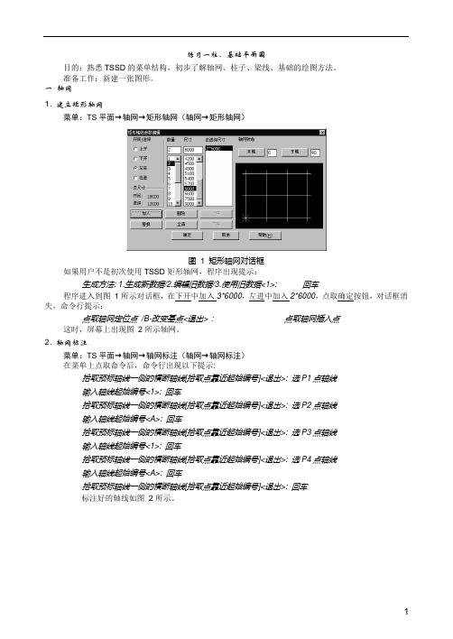
一轴网1. 建立矩形轴网菜单:TS平面→轴网→矩形轴网(轴网→矩形轴网)图1 矩形轴网对话框如果用户不是初次使用TSSD矩形轴网,程序出现提示:生成方法: 1.生成新数据/2.编辑旧数据/3.使用旧数据<1>: 回车程序进入到图1所示对话框,在下开中加入3*6000,左进中加入2*6000,点取确定按钮,对话框消失,命令行提示:点取轴网定位点/B-改变基点<退出>:点取轴网插入点这时,屏幕上出现图2所示轴网。
2. 轴网标注菜单:TS平面→轴网→轴网标注(轴网→轴网标注)在菜单上点取命令后,命令行出现以下提示:拾取预标轴线一侧的横断轴线[拾取点靠近起始编号]<退出>: 选P1点轴线输入轴线起始编号<1>: 回车拾取预标轴线一侧的横断轴线[拾取点靠近起始编号]<退出>: 选P2点轴线输入轴线起始编号<A>: 回车拾取预标轴线一侧的横断轴线[拾取点靠近起始编号]<退出>: 选P3点轴线输入轴线起始编号<1>: 回车拾取预标轴线一侧的横断轴线[拾取点靠近起始编号]<退出>: 选P4点轴线输入轴线起始编号<A>: 回车拾取预标轴线一侧的横断轴线[拾取点靠近起始编号]<退出>: 回车标注好的轴线如图2所示。
图2矩形轴网标注在系统的缺省情况下,轴线将被显示成点划线,如果您在绘图中经常要捕捉轴线交点,可以通过点取点划开关命令,把轴线临时显示成实线;在出图前,再用点划开关命令把轴线变成点划线。
二建立柱网1. 方柱插入菜单:TS平面→柱子→插方类柱(柱子→插方类柱)在菜单上点取命令后,出现图3所示对话框,在对话框中输入图3中的数据,然后点取区域按钮,这时命令行上出现提示:图3方柱插入对话框点取柱插入区域第一角点<退出>: 图4中P1点取柱插入区域第二角点<退出>: 图4中P2生成如图4柱网。
Autodesk MEP Engineering Solution 商业用户指南说明书

Autodesk®MEP Engineering SolutionSee inside the walls.AutoCAD®MEPDraft. Design. DeliverBenefit from greater drafting productivity, better accuracy, and design coordination opportunities. MEP designers and drafters are spending too much time on repetitive tasks. Autodesk offers a broad suite of solutions to help MEP professionals stay ahead of the competition and remain competitive. With AutoCAD MEP, production of construction documents is automated, helping to save time and allowing for the creation of single-line and double-line systems in addition to schematics. Whetheryou are working on a building project led by an architect or partnering with professionals from other disciplines such as structural and civil engineering for the design of water/wastewater facilities, AutoCAD MEP allows you to work in the familiar AutoCAD environment while implementing new systems and documentation tools at your own pace. Better Design Accuracy With constant requests to accommodate lastminute changes, MEP professionals need toefficiently create and edit designs. Using AutoCADMEP, you can more easily assess designs, sizing, andsystem balances with integrated calculators thathelp ensure accuracy. Errors are minimized with automated drafting tasks and built in calculators.AutoCAD MEP software helps to enhance drafting productivity and allows you to more smoothly integrate discipline-specific design and documentation tools.Coordinate Design InformationWith continuous pressure to reduce costs, youcan help reduce requests for information (RFIs)and costly design changes in the field with moreaccurate and consistent construction documentsproduced with AutoCAD MEP. Design systems usingreal-world parts and equipment, which can be usedthroughout the fabrication and construction of thebuilding helping to save time and money.Collaborate More EffectivelySince most projects require collaboration withprofessionals from other disciplines, take advantageof architectural and structural plans developedusing AutoCAD-based software applications tobetter coordinate with your extended team.AutoCAD MEP software helps you to minimizeinterferences prior to construction, allowing greatercoordination and collaboration.AutoCAD MEP helps to provide increased drafting productivity, better accuracy and design coordination opportunities forMEP designers and drafters.Fast. Faster. Fastest workflowHelp improve design accuracy by automating repetitive drafting tasks, reviewing and checking your designs, and simulating sizing and system balances.Familiar AutoCAD EnvironmentAutoCAD MEP is built on AutoCAD®, providing you with access to all of the commands you expect. Protect your investment in training whilst accessing discipline specific tools at your own pace. Industry-Based or Task-Based WorkspacesIf you work in a multidisciplinary firm and perform several different design tasks, such as the designof HVAC and piping systems, workspaces are particularly useful. You can use them to save user interface configurations that are tailored to specific tasks. Once the workspaces are created, you can quickly switch between them as needed.Schematic DesignMore easily create riser diagrams and schematicplans with enhanced schematic tool palettesthat logically group commonly used tools. TheProperties palette provides easier schematic objectconfigurations. Convert existing AutoCAD blocks toschematic symbols for quick use in schematic design.Fabrication for MEP ContractorsWith smoother integration of fabrication partnertools into AutoCAD MEP software, MEP designers,drafters and contractors can leverage theirAutoCAD MEP design for the fabrication of sheetmetal, plumbing, and piping making it easier tocreate shop drawings.Single/Double-Line DesignAutomate your worflow by creating constructiondocuments more efficiently with single line fordesign development and convert automatically todouble line for construction documents. Lay outmechanical systems in single line with unsizedparts early in the design process, and then useduct-sizing tools and convert the layout to doubleline. Enhanced sizing tools help to increase draftingproductivity when moving from design developmentto construction documentation.Smart Annotation of ObjectsAnnotate once for all scales. Annotative textand symbols automatically change for each viewbased on the scale. You can annotate objects withlabels that consist of text or block definitions.The information in the label comes from objectproperties, such as connection size.Single-line duct design Double-line duct designDesign, decide and draw the systemAssess your vision and enhance your efficiency with purpose-built software for MEP designers and drafters.Engineering Display ThemesTypically, manual properties of an object—such as a duct’s friction loss or velocity—are not visible in a drawing. Display themes let you incorporate such nongraphical data by using colors, fills, or hatches to highlight objects that meet criteria you establish in a display theme style. For example, check your HVAC design calculations based on friction loss or velocity to assess performance for a particular area or room. Also use the display theme By Pressure Class to visually show the high, medium, and low pressure per piping class to more easily identify potential design flaws.Synchronized SchedulesDesigners and drafters can schedule engineering system data, calculate values, and use new table styles to lay out room and analysis schedules. Schedules are automatically updated as the design changes, assisting in the reduction of errors. Create schedules as you lay out your design, and see the schedule populate automatically, helping to save time. You can create schedules with varying levelsof detail by defining and attaching sets of properties to object styles or to individual objects and then extracting and displaying the data in a schedule table.Seamless Sections and ElevationsNo longer wait until the end of your design process to create sections and elevations, instead, quickly create them at any time. You can control the size and shape of the section you generate and assign materials to the section for an optimal visual representation of the sectioned objects. Drawing ManagementThe Drawing Management feature formalizes and automates the processes related to building system design and documentation. The feature provides automated tools that aid in the management, viewing, and construction of your building systems. When your project files are managed with this feature, you have greater consistency in all aspects of the project, and everyone on the design team has a centralized project environment for accessing the most current documents. Powerful linking features help enable that source files can be distributed over many different locations on your computeror on a network, enabling different people to worksimultaneously on the same project.Choose your GearAutoCAD MEP software is an essential element in a complementary, comprehensive Autodesk engineering solution for MEP professionals.AutoCAD Drive your projects from concept to completion with the powerful AutoCAD-based documentation tools. Work more efficiently with automation, management, and editing tools that minimize repetitive tasks and speed your time to completion. AutoCAD ® software is interoperable with AutoCAD MEP software.Collaboration Autodesk Navisworks Manage Autodesk ® Navisworks ® software solutions help enable project design and building professionals to unite their contributions into a single, synchronized building information model. By helping enable team members to more reliably share, combine, review, and correct detailed 3D design models of any size or format, Autodesk Navisworks solutions are at theheart of your design workflow.Autodesk Design ReviewAccelerate your reviews with Autodesk ® DesignReview software, the free*, integrated, all-digitalway to view, print, mark up, and compare versions ofdrawings, maps, and models—without the originaldesign-creation software. For everyone in thereview chain, sharing and collaborating on designshas never been this easy.Design and DocumentationAutoCAD MEPAutoCAD ® MEP software is the AutoCAD ®software for mechanical, electrical, and plumbingdesigners and drafters. Creation and coordinationof construction documents is more efficient withAutoCAD MEP’s more intuitive systems drawingand design tools.AutoCAD P&IDCreate, modify, and manage piping andinstrumentation diagrams with AutoCAD P&IDsoftware. Built on the latest AutoCAD ® platform,AutoCAD P&ID software is easy to use and familiarto designers and engineers, so design teams canstart immediately with minimal training. Commontasks performed every day are streamlined andautomated to boost productivity, while componentand line information is easily accessed by designersas they work. Autodesk Seek Powerful, dynamic Autodesk ® Seek web service replaces bulky paper catalogs and static online directories. Connect architects and engineers with building product manufacturers. Enhance design efficiency. Streamline project workflows by reducing the hassle of time-consuming searches or the need todesign a product or component for each new project.Autodesk Buzzsaw The Autodesk ® Buzzsaw ® on-demand collaborative project management solution helps your organization centralize building design and construction-related documents, simplify communication, and make collaboration smoother so you can execute projects more successfully based on more accurate information and timely decisions.。
Autodesk 3D 制造解决方案用户指南说明书
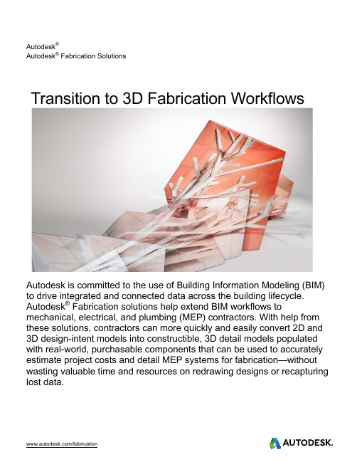
Autodesk®Autodesk® Fabrication SolutionsTransition to 3D Fabrication Workflows Autodesk is committed to the use of Building Information Modeling (BIM) to drive integrated and connected data across the building lifecycle. Autodesk® Fabrication solutions help extend BIM workflows to mechanical, electrical, and plumbing (MEP) contractors. With help from these solutions, contractors can more quickly and easily convert 2D and 3D design-intent models into constructible, 3D detail models populated with real-world, purchasable components that can be used to accurately estimate project costs and detail MEP systems for fabrication—without wasting valuable time and resources on redrawing designs or recapturing lost data.ContentsIntroduction (3)The emergence of advanced 3D workflows (3)A unified database (4)More accurate estimates (5)Move directly into fabrication (5)Change is easy (5)IntroductionAccording to the McGraw-Hill Construction Prefabrication and Modularization SmartMarket Report (2011), prefabrication and modularization are seeing increasing popularity among design and construction professionals. Many see these practices as ways to improve worksite productivity, safety, competitive advantage, and ROI. Others value them for their ability to reduce construction waste and build greener projects. Among the hundreds of AEC professionals surveyed, the highest levels of current and future usage were reported among mechanical contractors, design-build firms, and subcontractors, including mechanical, electrical, and plumbing (MEP) systems fabricators.MEP systems detailers and fabricators are responsible for converting the design-intent models into detail-level, constructible fabrication models populated with either real-world purchasable or fabricatable components that, in turn, help enable more accurate estimates of project costs and drive MEP systems fabrication.Traditionally, detailers/fabricators received MEP design-intent drawings in one or more 2D formats, including DWG™, PDF, JPEG, and even, in some cases, paper. To convert these types of 2D drawings to a format useful for cost estimation and fabrication, contractors using traditional tools are forced to manually redraw the designs by hand—an approach that is time-consuming, often results in data loss, and ultimately produces a detailed, but still a flat, 2D design that is difficult for other disciplines to interpret properly.More recently, MEP designers and engineers have started trending toward providing 3D design-intent models produced in software such as Autodesk® Revit® or Autodesk® AutoCAD® MEP. 3D models are easier to understand than 2D drawings, but these schematic models nonetheless still lack intelligence and require time-consuming, hands-on redrawing of their generic model components into real-world, purchasable and fabricatable components.The emergence of advanced 3D workflowsThe emergence of Building Information Modeling (BIM) over the past decade—along with its associated advancements in trade and discipline interoperability—has caused these inefficient ways of working to begin giving way to new, more productive workflows.BIM first gained traction among architects, who gradually pushed it downstream to structural, civil, and MEP engineers. Today, BIM use is widespread in Architecture, Engineering, and Construction (AEC) industries. Project owners and government agencies around the world have begun mandating its use on projects of every size and its impact has permeated every stage of the design process—including MEP systems fabrication.Figure 1. Fabrication level detail model of HVAC systemAutodesk ® Fabrication solutions provide new tools that help MEP contractors to streamline and accelerate theirworkflows, whether they continue to work with 2D inputmodels or transition to a complete, end-to-end 3D workflow.When working with clients who continue to produce 2Ddeliverables, MEP contractors can take advantage of toolsthat allow them to significantly accelerate the manualredrawing process. These tools simultaneously incorporateboth constructability and intelligence into the redrawn models.The immediate benefits are increased productivity,coordination, and competitive advantage. In the longer term,contractors who take this approach have future-proofed their firms against the growing number of owners, governmentagencies, architects, and MEP engineers who require the use of intelligent 3D workflows. Using Autodesk Fabrication CADmep or Autodesk Fabrication ESTmep, MEP contractors who adopt an end-to-end 3D workflow can significantly reduce manual redrawing by automatically convert an incoming 3D design model into afabrication-level detailed model, swapping out the generic items for, or mapping them to specific, real-world, intelligent components with associated pricing, labor costs, performance information, and more.For example, a contractor receiving a PDF layout of the MEP systems can use Autodesk Fabrication CADmep orAutodesk Fabrication ESTmep to quickly trace over elements and create an accurate model of the systems in a fraction of the time required by remodeling from scratch. If the contractor receives a 3D model created in either Revit or AutoCAD MEP, he or she can easily convert the systems. Once the model is converted, the contractor can ensure that the systems are clash-free prior to beginning estimation and fabrication.This approach saves a tremendous amount of time and minimizes human error as it eliminates both manual redrawing and all associated data loss. The resulting fabrication model is more geometrically—and thus spatially—accurate and ready for coordination with other trades and services.A unified databaseAt the heart of the Autodesk Fabrication solutions is a single, integrated database of content and information. In traditional fabrication detailing and estimating workflows, data exists in software-specific, disconnected silos. As a result, contractors have difficulty transferring data among detail drawings, estimates, and fabrication outputs with disparate file formats from disparate software solutions. Thus, without a common database, information is commonly lost in transfer, often resulting in inaccurate cost estimates, detailing errors, and change orders. In many cases, what the contractor ends up estimating or fabricating is not what he or she originally designed.The integrated Autodesk Fabrication content libraries and database, however, are common to all three fabricationdisciplines, the detail modeling, estimating, and fabrication solutions, which:∙Support detailing, fabrication, and installation workflows ∙Create accurate, competitive bids and cost estimates ∙ Manage and control the ductwork manufacturing production lineWith a common database, when something changes in one application—drawing, estimation, or fabrication—it is reflected throughout the products, with no loss of data.Figure 3. Common database for Fabrication CADmep, ESTmep and CAMductFigure 2. Use 2D deliverables to create detail modelMore accurate estimatesIn this optimized, intelligent 3D workflow environment, library elements possess values—such as material, fabrication, and labor costs—that project estimators can easily capture. As MEP contractors add components to or remove them from the model, they are simultaneously adding or removing the costs associated with purchasing, fabricating, and installing the components. Linking components to costing helps enable MEP contractors to simultaneously create highly accurate bids that not only account for parts, but for labor as well.Move directly into fabricationOnce the contractors have submitted a bid and won a project, they can move the model created to estimate thebid directly into Autodesk Fabrication CADmep or ESTmep for further detailing, with no loss of time and data andno need to manually redraw content. Comprehensive libraries of 3D parametric fixtures and fittings helpcontractors meet manufacturing requirements.Change is easyBy adopting Autodesk Fabrication solutions, contractors can produce more accurate estimates and bids, quicklygenerate fabrication-level models, and move directly to fabrication, retaining the “I” in BIM throughout. Asdiscussed in the Prefabrication and Modularization SmartMarket Report, many MEP contractors have alreadymade the switch to intelligent, 3D fabrication workflows.Many more, however, are reluctant to make the switch, being concerned with adoption issues such as the learningcurve and loss of productivity due to lack of understanding. Fortunately, the learning curve is relatively easybecause Autodesk Fabrication CADmep is based on AutoCAD software, sharing the same interface and basic toolset. The most important part of setting up the solution involves articulating the basic rules that will govern theconversion or mapping process and setting up the mapping and costs based on your company’s standards.For example, there are two methods for exporting Revit content so that it can be used within CADmep.The first method is Store Design Line Elements. This method should be used where Revit elements can bematched to corresponding Items in CADmep. These are usually standard elements such as ducts, pipes, cabletrays, straights, and fittings. This process will convert the Revit System to a CADmep Design Line.The second method, Store Graphic Elements, should be used where no match can be made between Revitelements and CADmep Items. A custom Revit Family of an air handling unit would be an example of a Revitelement with no corresponding CADmep Item. The raw geometry of the exported Revit elements is used to createCADmep Items with the connectors at the correct locations..Autodesk, the Autodesk logo are registered trademarks or trademarks of Autodesk, Inc., and/or its subsidiaries and/or affiliates in the USA and/or other countries. All other brand names, product names, or trademarks belong to their respective holders. Autodesk reserves the right to alter product and services offerings, and specifications and pricing at any time without notice, and is not responsible for typographical or graphical errors that may appear in this document.© 2014 Autodesk, Inc. All rights reserved.。
Autodesk MEP Fabrication 2017 制定和详细工作流程说明书

MSF 20578-LCapitalize on MEP Fabrication Workflow : Close the Loop with Revit Detailing CustomizationSpeaker: Julien DrouetAutodeskLabs Assistant: Olivier BayleAutodeskDescriptionThis class is about the MEP Fabrication database customization:How to create new services, new items from pattern templates, and so on.The ultimate goal is to use it in Revit software, taking advantages of all new features and capabilities provided by Revit 2017 software—and figure out all the value of using Fabrication content in the detailing phase to capitalize on design, optimize construction, and save costs.This session features Revit and Fabrication CAMduct and ESTmepYour AU Expert(s)Ba sed in Autodesk, Inc.’s, Paris office in France, Julien Drouet is senior technical specialist in the EMEA (Europe, the Middle East, and Africa) Architecture, Engineering, and Construction (AEC) Team, focused on the construction and MEP (mechanical, electrical, and plumbing) portfolio.Julien is an electrical engineer with 20 years experience in the building, engineering, and construction industry. He has beeninvolved in Autodesk’s MEP product adoption for 9 years, and he’s been in charge of the MEP Fabric ation Solutions since Autodesk’s first MEP fabrication product release.https:///in/julien-drouetVillage BIM Blog Beyond Design BlogOlivier Bayle has over 19 years experience in structural design, in a variety of fields ranging from simple construction schemes to highly technical engineering projects.Prior to coming to Autodesk (Robobat company acquisition), Olivier worked as civil engineer in steel, concrete and timber design.At Autodesk, Olivier has further engaged clients with BIM solutions, workflow integration and developing best practices in 3D visualizations, clash/collision detection and 5D construction simulations.Currently, he is one of writer of Village BIM Blog .Olivier holds a Graduate civil engineer from Clermont Ferrand – Francehttps:///in/olivier-bayleVillage BIM BlogCreate a new ItemLet’s start with choosing the item we want to create.The one we will create from scratch is providing by the Manufacturer ELKHART Product Corporation. The imperial database contains already most of the copper soldered content library Elkhart is currently selling.We can notice that the N° 111R Reduced T ee item doesn’t exist in the current database. We will focus on it.Identify the Manufacturer DataOn Elkhart’s website, we will get the information needed to create the item.Information required are:∙Lay in dimensions :∙Description∙Weight∙Code∙dimensions∙Pricelist∙PictureIdentify the pattern template to be usedIn Autodesk Fabrication solutions, new items have to be created from an item pattern template. So you need to identify which pattern template (CID) you will use to create the item you want to. To do so, go in the help and navigate to“Fabrication User’s Guide Help→ Creating Content→Before you Begin CreatingContent→Common Pattern Numbers and select pipeworkWe want to create a Reducing Tee:We will use CID 2160.Start creating the itemNow we have the manufacturer data, and the CID to use, let’s start to create the item CAMduct consoleLaunch CAMduct, and open a blank Job (it could be done with ESTmep as well).To create a new item from a pattern template, we have to launch the CAMduct console. To do so, maintain CTRL + Shift and type CType the following command: MAKEPAT 2160It opens the following takeoff window:Click on “accept” in the bottom right corner. Browse in the folders to the one where you want to save your item, give him a name and click on SaveCustomize the thumbnailNext step will be to customize the thumbnail displayed in the item folder.First you have to save the thumbnail in the appropriate folder.In the dataset folder, copy the file “111R.png”Then go to:C:/Users/Public/Documents/Autodesk/Fabrication 2017/Imperial Content/V3.04/ITEMS/ImperialContent/Mechanical/Systems/Elkhart/Soldered/Wrot Copper/Paste the file “111R.png”.Rename it with the same name as the ITM file you’ve created a couple of minutes ago. Here, rename it like this: “No111R - Reducing Tee.png”As the system already created a png file with this name, you will be asked to save it as “No111R - Reducing Tee (2).png”. Do it.Then, go in the Item Folders, select the new item you’ve just created, right click and select “properties”.In the pattern template tab, click on the “Change” but tonSelect the No111R - Reducing Tee (2).png and save.Create a product listSelect the item and right click: create a product list. Close the product list windows and click on “accept. Select the file in the list and saveSet the optionsNow we will set the common options, those that doesn’t depend on the item dimension. Right click on the item and select “Edit”On the Dimension tab:Set “Left” and “Right Extension” on auto and lock the padlockSet the Angle #1 to 90. And lock.Lock “Offset #1” to 0Set “Extension #1” on “auto” and lockSet from “Branch diameter #2” to “Extension #2” on 0 and lockClick on “redraw”.It should look like this:On the Item tab:Set material on Copper and Standard on ASTM B88 (Elkhart).To know how to create a new material, click here.Don’t forget to check the “Centreline Input box.Set the connectorsNew Connectors Creation is described in this Autodesk Fabrication Help chapter In our case, we will use existing connectors and set them to our item.To do so, l et’s go in the connectors tab.We have 3 connectors to set: C1, C2 and C3For the example we are working on, we will use the same connector:ELK_C-WCU. You can find it in the drop down list, in Elkhart group.Set each connector on ELK_C-WCU and lock themFill the listFor the next step we will fill the product list.Open the excel spreadsheet with manufacturer product information“111R_Reducing_Tee_Wrot_Lay_In_Dimensions.xlsx”We have to understand the manufacturer drawing and match the dimensions provided with those of the pattern template.Pipe diameter is the pipe size that will connect from the left to the Tee. So it is the 1st size indicated in the descriptionRight diameter is the pipe size that will connect from the right to the Tee. So it is the 2nd size indicated in the descriptionBranch diameter is the pipe size that will connect from the top to the Tee. So it is the 3rd size indicated in the description“A” from the Manufacturer drawing is the Inset #1“A+B” from the Manufacturer drawing is “pipe length + right length”“C” from the Manufacturer drawing is Branch Length #1“Pipe length” is “A” from the manufacturer + ½ branch diameter“Right length" is “A+B-pipe length = A+B-A-½ branch diameter = B-½ branch diameter Reopen the product list windowWe will first create the columns needed.Click on the new buttonClick ok.Then redo it and enter the following column:We will add new columns, that won’t be dimensions. To do so, re-click on the new column buttonSelect Weight, Order and IdManuallyLet’s fill the first line manually.Click ok and have a look on the geometry:By copy and paste an excel fileTo save maximum of time, the best is to prepare the excel spreadsheet that will fit with the product list in CAMduct.In our case, it would mean add columns for pipes sizes, set format value to number, remove columns unnecessary, add missing one (Id) and move it to fit with the product list organizationIt will look like this:The final Excel document is available in the dataset, open it:111R_Reducing_Tee_Wrot_Lay_In_Dimensions_reorganised_and_filled.xlsxWe are now able to copy and paste the spreadsheet content into the product listTo proceed, first select the cells in ExcelThen right click once here:It’s done:Click ok.Test the itemYou can now have access to the different references you’ve just create, through the drop down menu near Catalogue:Test with different references, click on accept to save the modificationsCreate the New ServiceTo use the new item we’ve just created, we have to create a new service to put it in.Let’s launch ESTmep for that.Select the Service from which you will startIn ESTmep, create a blank job and click on the database button.Click on the takeoff button and on the left hand side, select ServicesThe item is a copper Tee, which can be used for Sanitary Hot Water for instance. Let’s select the existing Hot Water Flow Service, and click on New.Answer yes to the question. Change the name of the Service.Create the Service template you will useThe new service created is using the same Service template as the Hot Water Flow. If we don’t want to modify the way the existing service is working, we have to create a new Service Template to apply to our new Service.Click on the New Service template button:Adjust the Service templateRename the new template, for instance “Mechanical - Elkhart-Copper-Soldered/Victaulic-Grooved-Copper_v1”Delete the existing button in the soldered tab, except the straight oneBrowse the Item Folders to Elkhart folder, and drag and drop the “Wrot Copper” folder to the soldered tab on the right hand sideYou can see your item creation in the list of items available in the Service. Click on ok (twice)Test it with ESTmepNow let’s test the new service in ESTmep, and especially the new item we’ve created. On the left hand side, select the service. Click on the straight pipe, choose 1” diameter. Then connect an elbow, a pipe and insert your Tee. You have to right click on your Teebutton, select “takeoff as a cut in”, and choose a relevant size (e.g. 1x1x1/2). Then connect a pipe on the branch.Now go to the Item tab, r ight click on your tee and select “cost breakdown”All values are equal to zero. It’s because you didn’t map your item product list with the manufacturer pricelist.Click on the database button, then on Costing button and select pricelist. In the supplier Group, select Elkhart and then click on the N ew Pricelist button and chose “New empty table”Name the pricelist “AU Class Elkhart Pricelist”Open the Excel “111R_Reducing_Tee_Wrot_pricelist.xls x” file (combination of“111R_Reducing_Tee_Wrot_Lay_In_Dimensions_reorganised_and_filled.xlsx” and “plist_WROT.xls”.Select all the filled cells and copy. In ESTmep, right click in the green area and pastMap Field Id on Use 1 and Field Cost on Use 2, as below:Here is the result:Click OkBack in the Items tab, reselect your Tee, and right click, properties.Select the costing tab, and in the “M-Rate”dropdown menu select the pricelist you’ve just createdBack in the costbreakdown: you have now the price for your Tee:Use in RevitLet’s move to Revit now.Open “56750_M_Systems - 2017 - Start.rvt” and open the 3D Plumbing view.In the MEP Fabrication Part Palette, click on Settings. Reload configuration and add the new service we’ve created.Conversion toolNow we will use the nice conversion feature launched with Revit 2017.Revit pipework selectionSelect the full hot water system. Clic k on “Design to fabrication” button”. Choose “Hot Water Flow” service and then OkThe full hot water system has been converted into a fabrication service. Select thelongest straight pipe and click on “Optimize length”.Select the full service and isolate it:Then export the fabrication elements you’ve just converted, with the add-ins tool “Revit Extension for Fabrication”Then undo the conversionReselect the hot water system, and convert it in the new service we created “AU Class Hot Water”:You get a warning message:Fittings weren’t recognized, only straight pipes have been converted.To fix this issue, back in ESTmep and go to the service template settings, and right click on a button, an elbow for instance and select “button properties”:The field “Button Code” is empty. The button code is used by the Design Line technology to map nodes definition with compatible fittings. This technology is used by Revit as well in the conversion process. So we need to put the right button code for each fittings that will be used in Revit.For this elbow, the code is “Bend”Fill the button code for our reduced Tee, with code “RedILTee” and the equal Tees with code “RedBranch-90”.Click on ok to save the modifications.Back in Revit, undo the design to fabrication conversion.Reload the MEP Fabrication configuration to load the Database modifications in yourRevit project.Reselect the hot water system, a nd convert it in the new service we created “AU Class Hot Water”. You don’t have the message, the conversion process worked.Optimize length, reselect the full service and export it in a different name thanpreviously.Export & comparisonWhy did we convert the hot water system twice?Actually, the goal was to emphasize the optimization introduced by the presence of a Reducing Tee in the 2nd service. Number of parts exported is a first clue.To verify this optimization, let’s compare the 2 jobs we’ve created in ESTmep.Launch ESTmep and open the first Job, containing 84 parts.Click on “Estimated Summary.Now close the job and open the 2nd job, obtained with our service.Click once again on Estimating summary:Using our New Se rvice “AU Class Hot Water” saved 17.7% of moneyEnd。
探索者_结构软件使用说明(最全最好)

%%132 %%133 %%134 %%135 %%136 %%137 %%138 %%140 %%141 %%142 %%143 %%144 %%145 %%146 %%147 %%u %%o
三级钢符号 四级钢符号 特殊钢筋 L 型钢 H 型钢 槽型钢 工字钢 上标文字开 上标文字关 下标文字开 下标文字关 文字放大 1.25 倍 文字缩小 0.8 倍 小于等于号≤ 大于等于号≥ 带下划线字体 带上划线字体
图 1-1.9 安装结束提示对话框
TSSD2006 版软件
用鼠标双击桌面探索者 TSSD 图标,即可进入如图 1-1.10 所示的软件操作界面,使用 TSSD 提供的各 项功能来绘制、编辑结构图。
-5-
图 1-1.10
本软件的绘图环境
一、TSSD2006 文档
TSSD2006 的文档内容包括使用手册和联机文档。 1.2 使用手册 TSSD2006 使用说明以书面形式全面介绍 TSSD2006 版的各项功能和使用方法。 1.3 联机文档 TSSD2006 联机帮助以 Windows 帮助文件的形式,介绍 TSSD2006 版的各项功能和使用说明。 其他帮助资源 通过探索者公司 Web 站点 可以获得 TSSD 软件产品的最新信息, 并可随时进 行软件升级和完善。 TSSD2006 菜单 TSSD2006 的菜单分为下拉菜单和屏幕菜单两种,下拉菜单分为 TS 平面、TS 构件、TS 计算和 TS 工 具四大类,参见图 1-1.11 所示。
-1-
图 1-1.1 启动安装程序对话框 2、 程序进入安装准备阶段,如图 1-1.2 所示:
图1-1.2 安装准备对话框 3、 准备结束后,则弹出如图 1-1.3 所示 TSSD 结构 CAD 安装对话框:
探索者三维结构设计平台软件说明书V2019
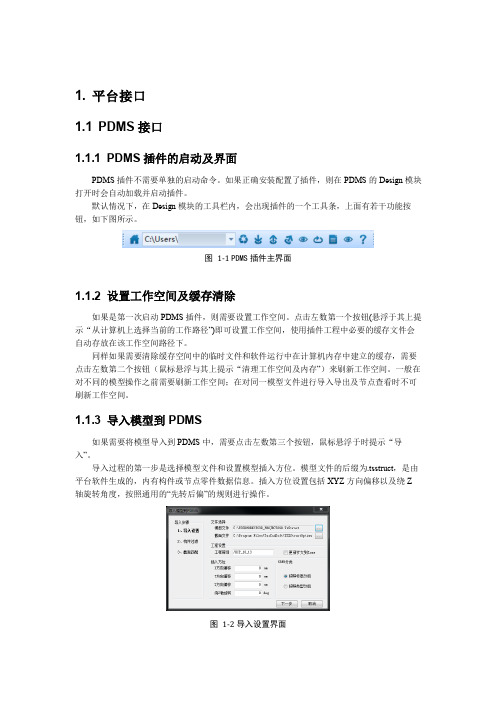
1. 平台接口1.1 PDMS接口1.1.1 PDMS插件的启动及界面PDMS插件不需要单独的启动命令。
如果正确安装配置了插件,则在PDMS的Design模块打开时会自动加载并启动插件。
默认情况下,在Design模块的工具栏内,会出现插件的一个工具条,上面有若干功能按钮,如下图所示。
图1-1 PDMS插件主界面1.1.2 设置工作空间及缓存清除如果是第一次启动PDMS插件,则需要设置工作空间。
点击左数第一个按钮(悬浮于其上提示“从计算机上选择当前的工作路径”)即可设置工作空间,使用插件工程中必要的缓存文件会自动存放在该工作空间路径下。
同样如果需要清除缓存空间中的临时文件和软件运行中在计算机内存中建立的缓存,需要点击左数第二个按钮(鼠标悬浮与其上提示“清理工作空间及内存”)来刷新工作空间。
一般在对不同的模型操作之前需要刷新工作空间;在对同一模型文件进行导入导出及节点查看时不可刷新工作空间。
1.1.3 导入模型到PDMS如果需要将模型导入到PDMS中,需要点击左数第三个按钮,鼠标悬浮于时提示“导入”。
导入过程的第一步是选择模型文件和设置模型插入方位。
模型文件的后缀为.tsstruct,是由平台软件生成的,内有构件或节点零件数据信息。
插入方位设置包括XYZ方向偏移以及绕Z轴旋转角度,按照通用的“先转后偏”的规则进行操作。
图1-2导入设置界面导入过程的第二步是进行构件过滤。
可按需要进行层高过滤和构件类型过滤。
如果选择了“导入轴网”则会交互式删除或保留现有轴网,并加入模型中的轴网。
导入过程的第一步是选择模型文件与截面文件。
模型文件的后缀为.tsstruct,是由平台软件生成的,内有构件或节点零件数据信息。
截面文件用于将构件的截面成功地映射到PDMS中截面库内的截面。
如果安装过定制的补丁包,则会自动选择好匹配文件。
图1-3 模型匹配选择模型后,还需要设定一些导入设置项。
包括需要导入的内容:是否导入附属构件(楼梯、栏杆等)、是否导入轴线、工程前缀(PDMS的一个工程中不允许出现同名,因此需要设定一个工程前缀)、插入方位(插入点和旋转角度)。
3D建模与设计软件使用指南

3D建模与设计软件使用指南第一章:介绍3D建模与设计软件是现代设计领域中使用广泛的工具,通过3D建模可以模拟并呈现出各种设计概念和创意。
本篇文章将为读者提供一份3D建模与设计软件的使用指南,帮助读者了解软件的基本原理和使用方法,并且介绍几款常用的3D建模与设计软件。
第二章:基础知识在开始使用3D建模与设计软件之前,了解一些基础知识是十分重要的。
首先,了解3D建模的原理和概念,包括物体的三维空间坐标系统、多边形建模和贝塞尔曲线等。
其次,掌握3D建模的常用工具和技术,如建模、贴图、材质和渲染等。
最后,了解一些常见的3D文件格式,如OBJ、STL和FBX等。
第三章:AutoCADAutoCAD是一款功能强大的3D建模软件,被广泛应用于工程设计和建筑设计领域。
使用AutoCAD,用户可以创建复杂的建筑结构、机械零件和产品原型等。
本章将介绍AutoCAD的界面和工具,以及基本的建模和编辑技术。
第四章:SketchUpSketchUp是一款易学易用的3D建模软件,它适用于各种设计领域,包括建筑设计、室内设计和景观设计等。
SketchUp使用简单直观的绘图工具和操作方式,使得用户能够快速创建3D模型。
本章将介绍SketchUp的界面和工具,以及常用的建模和编辑技巧。
第五章:BlenderBlender是一款免费的开源3D建模和动画软件,它提供了先进的建模工具和强大的渲染引擎,可以用于创建高质量的3D动画和特效。
本章将介绍Blender的界面和工具,以及一些高级的建模和渲染技术。
第六章:SolidWorksSolidWorks是一款主要用于工程设计和机械设计的3D建模软件,它支持快速的建模和分析功能,能够帮助用户设计出复杂的零件和装配体。
本章将介绍SolidWorks的界面和工具,以及常用的建模和装配技巧。
第七章:其他3D建模软件除了上述几款常用的3D建模软件外,还有许多其他优秀的3D建模软件值得一提,如3ds Max、Maya和Rhino等。
Autodesk Revit MEP 2013 Update Enhancement List说明书
AUTODESK® REVIT® MEP 2013Update Enhancement ListImprovements made in Update 2 build (20121003_2115):Autodesk® Revit® MEP 2013 Enhancements∙Improves stability when sizing Duct.∙Corrects the use of tees when specified in duct routing preferences within projects upgraded from Revit 2012.∙Improves stability when upgrading a pipe fitting connected to multiple systems.∙Improves stability when editing duct fitting size in the active view and then editing the duct fitting type in the Property Palette.Autodesk® Revit® Platform 2013 Enhancements∙Improves stability when Save to Central or Sync with Central.∙Improves stability when utilizing Create Assembly Views from the project browser.∙Improves stability when editing a label within the family editor.∙Improves stability when saving file to a location with low disc space.∙Improves stability when launching Export gbXML – Settings dialog.∙Improves stability and memory usage within graphics display.∙Improves stability during IFC data import which contains openings with no usable geometry.∙Improves stability when importing IFC data which imported into Revit 2012 with warnings.∙Improves import of clipped solids during IFC import.∙Improves IFC Export to support buildingSMART International IFC certification.∙Improves stability when linking or attached DWG files.∙Improves stability of printing after Export to DWG or DXF format.∙Improves stability when creating, duplicating or deleting a material in the Material Editor.∙Improves the retention of part parameters within a part upgraded from Revit 2012.∙Corrects ribbon tab population after installing .NET 4.5∙Improves stability while editing calculated values within a schedule after deleting a parameter used in a formula.∙Improves stability with schedules which contains a filter based upon a user defined parameter and elements in linked files do not contain the user defined parameter.∙Improves stability when opening Sun Settings dialog.∙Improves stability when editing Text Notes.∙Improves stability when upgrading Revit 2012 project to Revit 2013.∙Improves stability when moving a Crop Region which utilizes the disjoin option.∙Improves stability when upgrading 2012 project which contains analytical walls.∙Improves stability when adjusting multiple sketch lines of a floor at the same moment.∙Improves stability when editing the gutters on a roof object with the Add/Remove Segment tool.∙Improves stability when renaming a Stair run type or landing to ‘none’.∙Improves stability when using the ribbon Cancel Edit Mode button to exit Stair Edit Mode.∙Improves stability when using an open profile for a wall sweep.∙Improves stability when splitting a wall.Improvements made in Update 1 build (20120716_1115):Autodesk® Revit® Architecture 2013 Enhancements∙Improves stability when closing a sketch editor, such as slab, site, etc., which create a large number of points.∙Improves creation of U-shaped winder stairs.∙Improves stability when editing winder stairs.∙Improves performance when many railings exist within a project.∙Improves stability when support type is not defined for stair.∙Improves railing representation in coarse view.Autodesk® Revit® Structure 2013 Enhancements∙Improves placement of analytical nodes when in 3D views.∙Improves stability when enabling “Show Analytical Model Categories in this View” when the Warning dialog is open.∙Improves creation consistency with Physical Wall when coping an Analytical Model Wall.∙Improves stability when editing an Opening within an object which spans to the boundary of an Analytical Surface.∙Corrects the reporting of the “Structural Parameter” on slabs.∙Improves masking of linked files by Mask and Filled regions in Structural Views.∙Improves stability when placing Rebar.∙Improves stability when copying Area or Path reinforcement between projects which have differing value for the Reinforcement Project Setting: “Host structural rebar”.∙Improves visibility of round rebar when displayed in fine detail level.Autodesk® Revit® MEP 2013 Enhancements∙Corrects the Slope value on placeholder pipe when slope is greater than 15 degrees.∙Improves consistency when applying a slope to a layout which contains a transition.∙Improves stability when splitting pipes which belong to different systems.∙Corrects visibility of the center line when displaying rise/drop symbols.∙Improves stability when opening a Revit 2012 project which contains a pipe placeholder schedule.∙Improves consistency of unit formatting within Panel Schedules .∙Improves consistency of adding circuits to equipment that are connected to a pipe or duct system.∙Improves stability when adding a device, which is connected to a wire, to a circuit.∙Improves display of annotation on duct and pipe transitions.∙Improves stability when inserting duct fittings.∙Improves stability when viewing Routing Solutions.Autodesk® Revit® Platform 2013 Enhancements∙Improves stability when opening projects from previous versions of Revit.∙Improves stability during Copy/Paste operations.∙Corrects display of solid filled regions with transparent backgrounds.∙Allows exporting of materials painted on elements to ODBC.∙Improves performance of opening and closing sketch mode in projects with many families.∙Improves stability when setting a Design Option as the Primary.∙Improves stability when Fixed Distance option for a divided path.∙Improves stability while browsing to Revit Server when there is no network connectivity.∙Improves export consistency of Space and Zone elements when multiple elements have the same name and number.∙Allows Raytrace mode to work with DirectX 9.∙Improves stability when using Raytrace mode with Hardware Acceleration disabled.∙Improves Raytrace mode rendering output.∙Improves Surface Transparency override by element for multiple selections.∙Improves printing consistency when tone mapping is enabled.∙Disables Sun and SunPath from being rendered in Raytrace mode.∙Improves stability when using manual exposure in Raytrace mode.∙Improves stability when rendering views.∙Improves stability and performance when using visualization features like Sky, Exposure, and Anti-Aliasing.∙Improves stability when importing IFC data which contains special characters.∙Improves the setting of custom parameter values during import of IFC data.∙Improves stability when importing IFC data which contains an invalid line pattern.∙Allows Markups from DWF to be exported to DWF.∙Improves stability when drag and drop a DWG file into a Revit project.∙Improves stability when importing DXF data.∙Improves dimension fidelity when exporting to DWG with export units set to Meter.∙Improves alignment of hatch and fill patterns when exporting to DWG.∙Improves stability when selecting a new host for an element within an In-place Wall.∙Improves section creation within a project with linked model.∙Improves stability when working with Materials.∙Improves the displayed Pattern Type assigned to an element with the Material Editor.∙Corrects the display of the materials category within the Paint interface.∙Corrects the printed display of fill patterns within perspective views.∙Improves stability of Type editing when multiple element types are in the selection set. Autodesk ® Revit® API 2013 Enhancements∙Allows Document.PostFailure to be used to post multiple errors during a single transaction that do not reference an ElementId.∙Improves stability using UIApplication.DoDragDrop when a Revit command (such as the Wall tool) was active.∙Improves stability by disabling keyboard shortcuts (except view zoom shortcuts) when a PreviewControl is active.∙Improves stability in ReferenceIntersector.FindNearest() when no matching target pick is found.∙Corrects validation logic to allow NewFamilyInstance to place face-based families on transformed family instances.∙Dimension.Above and Dimension.Below now update the dimension after their data is changed without requiring any user action.∙The properties MechanicalSystem.SystemType, ElectricalConnector.SystemType, PipeConnector.SystemType are obsolete in Revit 2013. Instead query the parameterRBS_DUCT_CONNECTOR_SYSTEM_CLASSIFICATION_PARAM on ConnectorElement.∙Corrects data reported with ConnectorManager.UnusedConnectors.∙Fixes a file corruption that could occur when extensible storage data was added to an element ina central file.∙Improves stability when saving a file with extensible storage data that overwrites an existing file that also contains extensible storage.∙RVT Links created with RevitLinkType.Create will remain loaded when the RVT containing the link is reopened.∙Previously, setting 'suppressBendRadius' to true in method Rebar.GetCenterlineCurves() would cause both fillet bends and user-drawn, parameterized arcs to be omitted from the collection ofcurves returned by the method. The method now omits only the fillet bends; the drawn arcs are included along with the straight edges.∙Updates Rebar.GetCenterlineCurves() method with an additional argument: a MultiplanarOption (enum), which should be set to IncludeAllMultiplanarCurves or IncludeOnlyPlanarCurves. Thisargument controls whether all curves of a multi-planar Rebar instance are returned, or only those which lie in the primary plane.∙Enables method puteDrivingCurves(). This method returns a collection of curves that includes the lines and arcs that drive the shape, but excludes fillets and hooks. It is equivalent to calling GetCenterlinCurves(adjustForSelfIntersection=false, suppressHooks=true,suppressBendRadius=true, multiplanarOption=IncludeOnlyPlanarCurves)∙Improvements have been made in RebarShape methods that deal with matching RebarShapes to collections of curves: CreateFromCurvesAndShape(), RebarShapeMatchesCurvesAndHooks().∙Corrects behavior ot RebarShape.Create() method to not ignore the out-of-plane bend diameter specified in the RebarShapeMultiplanarDefinition argument object, and always used an internaldefault value.Autodesk, DWF, FBX, Revit, ViewCube and 3ds Max are registered trademarks or trademarksof Autodesk, Inc., and/or its subsidiaries and/or affiliates,, in the USA and/or other countries. Allother brand names, product names, or trademarks belong to their respective holders. Autodeskreserves the right to alter product offerings and specifications at any time without notice, and isnot responsible for typographical or graphical errors that may appear in this document.Occasionally, Autodesk makes statements regarding planned or future development efforts forour existing or new products and services. These statements are not intended to be a promiseor guarantee of future delivery of products, services, or features but merely reflect our currentplans, which may change. The Company assumes no obligation to update these forward lookingstatements to reflect any change in circumstances, after the statements are made.© 2012 Autodesk, Inc. All rights reserved.。
3Dmine软件操作

3Dmine软件操作实验一:3Dmine软件基本操作 1.文件导航器:2.图层操作:3.图形工作窗:1( 切换到二维:在图形工作窗上直接右键,在弹出的下拉菜单中左键单击切换到二维,即可立即实现从当前三维视图到二维视图的切换。
2( 确定旋转中心:用户根据自己需要为图形确定一个中心,围绕中心对图形进行旋转。
3( XY剖面:将3D图形转到XY剖面上查看。
4( 从剪贴板粘贴线条:这是3DMine中独特的数据导入形式。
4.系统设计:实验二:钻孔数据库 1.建立数据库:数据库:一种有效的管理数据的工具,可以方便的对数据进行检索,管理。
用户可利用 3DMine创建数据库,将地质数据导入到数据库中;通过3DMine软件将数字形式的勘探资料用三维图形的形态来管理和利用。
在3DMine软件中使用的数据库是Microsoft Access数据库。
2.导入Excel表格:首先要根据Excel 表格及表格中的数据,按照“添加表格”过程,为对应的数据库建立表结构。
导入完成后,在层浏览器中点击数据库前边的,数据库会展开,将包含的表格显示出来3.表格操作:可以对该表格进行右键菜单显示的各项操作,如“添加记录”、“编辑记录”、“删除记录”、“删除所有记录”。
4.钻孔显示:有如下命令:显示钻孔数据库:若设置“地质图案”和“标注”:5.组合样品点:组合样品的过程也就是计算单工程样品品位的过程,在软件中有两种组合类型:一是将空间不等长的样长,按照指定的长度进行组合量化到一些离散点上,并且通过长度加权得到每个等长样品的品位;二是根据边界品位,将矿带(岩性)连续的样品通过品位与样长的加权计算出平均品位。
实验三:表面模型1. 线条生成DTM:在图形工作窗中调入线条文件:2.闭合线内生成DTM: 调入闭合线条:运行表面模型?闭合线内生成DTM,出现对话框如下:对于一条闭合线内还存在其他闭合线时,其他的闭合线是否也生成DTM,如果也生成DTM,则不选该项;如果不生成DTM,则选择该项,其他闭合线将不被填充,生成带洞的面。
- 1、下载文档前请自行甄别文档内容的完整性,平台不提供额外的编辑、内容补充、找答案等附加服务。
- 2、"仅部分预览"的文档,不可在线预览部分如存在完整性等问题,可反馈申请退款(可完整预览的文档不适用该条件!)。
- 3、如文档侵犯您的权益,请联系客服反馈,我们会尽快为您处理(人工客服工作时间:9:00-18:30)。
《探索者三维MEP设计软件》用户手册《探索者三维MEP设计软件》是北京探索者软件股份有限公司,基于Revit平台开发的设计软件,包括给排水、暖通、电气三个专业模块。
菜单功能分区明晰,对话窗口界面集成化,本地族库丰富,操作指令便捷,多种批量处理功能,方便机电设备以及设施的快速智能化建模,有助于设计人员提高设计效率和设计品质。
第一章软件的安装与启动本章说明《TSRMEP探索者三维MEP设计软件》的安装和启动方法及相关问题,了解这些内容,有助于您正确使用本软件。
1运行环境操作系统:XP/Window 7/ Window 8中文版;运行环境:Revit 2014/2015/2016。
2运行运行《TSRMEP探索者三维MEP设计软件》,探索者三维MEP设计软件包含水暖电三个专业,给排水包括探索者给排水、探索者消防两个模块,暖通包括探索者暖通风、探索者暖通水两个模块,电气包括探索者变配电室和探索者电气平面两个模块,各专业的功能需在探索者提供的相应的样板文件下操作,可在项目列表下直接单击启动相应专业的样板文件,也可单击新建,在新建项目对话窗口的样板文件下拉列表中选择。
屏幕的主界面如错误!未找到引用源。
所示。
图1-2.1 探索者MEP功能界面第二章探索者给排水、消防本章为TSZ给排水专业模块,用户可以以多种方式创建和连接管线,布置设备,并进行相应的调整。
1 设置1.1 系统设置功能:此命令用于设置给排水专业各系统的系统类型名称及缩写、系统分类、线型、颜色、线宽等参数。
点击命令,弹窗如0所示。
图2-1.1 系统设置标准模板:下拉菜单收起时显示的名称为当前模板,系统提供一个参考模板,下拉菜单中为所有模板列表,可切换使用。
分别表示新建模板、删除模板与修改模板名称。
新建模板与修改模板名称需在相应的弹窗中输入和修改模板名称,点击确定后保存;点击则直接删除当前模板,系统至少保留一个模板。
专业分类:选择“给排水”专业分类。
专业分类列表:对应于给排水专业,下拉菜单中含有给排水系统、消防系统和其他等专业子分类。
各专业模板信息列表:归属于专业分类,随不同专业分类的切换而显示对应的内容。
允许对系统类型名称、缩写、系统分类、线型、颜色和线宽、流态类型进行修改。
增加一行:点击后,在当前专业分类的模板信息列表中增加一行。
删除一行:点击选择某一行,删除一行处于激活状态,点击命令后,删除该行。
导入:导入外部的系统设置配置文件。
导出:将当前系统设置内容导出为外部的系统设置配置文件。
选择视图:选择将当前的系统设置内容应用于哪些项目视图中。
同时更新过滤器:按照当前的系统设置内容更新项目过滤器。
确定:在当前模板中完成修改后,点击确定,保存修改内容。
取消:不保存修改内容。
1.2 管配专业功能:此命令用于设置当前项目中各类系统管道所属的专业分类(给排水或者暖通)。
点击命令,弹窗如02所示。
图2-1.2 管配专业系统类型:读取当前项目中所有的管道系统类型。
专业:设置每一管道系统所属的专业(给排水或者暖通)。
1.3 管压等级功能:设置每一个管道类型的“管压等级”参数值。
点击命令,弹窗如03所示。
图2-1.3 管压等级管道类型:读取当前项目中的所有管道类型值。
压力等级:设置每一管道类型的压力等级值。
2 管线2.1 创建横管功能:在平面视图中创建横管。
点击命令,弹窗如图2-2.1所示。
图2-2.1 创建横管专业分类:设置管道所属的专业分类(给排水或者暖通)。
管道类型:管道的材质、接头形式。
系统类型:管道归属的系统类型,采用当前标准模板的系统设置。
压力等级:设置管道类型的压力等级值。
公称直径:管道公称直径(DN), 下拉菜单中提供参考值,并允许输入合理值。
坡度:单位为%,下拉菜单中提供参考值,且允许输入。
以绘制横管时的起点为端点参照,正值表示坡度升高,负值表示坡度降低。
Revit。
Revit。
光标离开窗体,命令行提示:请绘制横管起点。
在平面视图中点击一点命令行提示:请绘制横管下一点。
连续点击多个不同点,管道连续创建,中心线夹角不小于90度时,管道自动创建弯头。
中心线夹角小于90度时,管道用两个弯头和一根短管连接。
2.2 绘制管道功能:直接绘制水平、垂直和倾斜管道。
在平面、立面和三维视图均可执行操作。
具体说明请参照Revit的系统→卫浴和管道→管道功能。
2.3 创建立管功能:在平面视图中创建立管。
点击命令,弹窗如图2-2.2所示。
图2-2.2 创建立管专业分类:设置管道所属的专业分类(给排水或者暖通)。
编号、楼号:管道标识数据,由用户输入。
管道类型:管道的材质、接头形式。
(DN), 下拉菜单中提供参考值,并允许输入合理值。
设置立管编号是否随着创建次数的增加而按照一定规律进行递增,可选择不递增、按数字编号递增、按英文编号递增。
起点定位参数。
参照层标高,光标离开窗体,命令行提示:请绘制立管点。
参照横管,光标离开窗体,命令行提示:请在横管上点击绘制立管点。
参照层标高时,单击平面视图上任意一点,完成操作。
参照横管时,单击横管上任意一点,完成操作。
2.4 平行管道功能:直接创建多根平行横管。
点击命令,命令行提示:请绘制横管起点!在平面视图上点击一点后,命令行提示:请绘制管道下一点!在平面视图上点击另一点后,命令行提示:请绘制管道下一点(按下ESC退出路由绘制)!此时,如按下Esc键退出时,软件弹窗如图2-2.3所示:图2-2.3 平行管道序号:横管生成次序。
序号1横管为窗口弹出前绘制的横管,其他序号为参照序号1生成的横管。
竖向偏移:序号1横管的竖向偏移不允许修改。
增加:增加一行。
首次点击增加,激活删除。
删除:删除一行。
序号1横管不允许删除。
第一根定位横管设置:对序号1横管进行参照标高的设置。
点击确定,完成创建,效果图见图2-2.4。
图2-2.4 平行管道效果图2.5 单横多横功能:参照所选横管,创建多根平行横管。
点击命令,命令行提示:请框选横管!当在平面视图中框选横管后,软件继续提示如下:请选择横管!选择横管后,弹窗如图2-2.5所示。
图2-2.5 单横多横序号:横管生成次序。
序号1横管为窗口弹出前绘制的横管,其他序号为参照序号1生成的横管。
增加:增加一行。
首次点击增加,激活删除。
删除:删除一行。
序号1横管不允许删除,点击序号1横管,删除处于非激活状态。
第一根定位横管设置:对序号1横管进行参照标高的设置。
点击确定,完成创建,效果图见图2-2.6。
图2-2.6 单横多横效果图2.6 多立多横功能:参照单根立管上的横管布置,在多个立管中创建相同的横管布置。
点击命令,命令行提示:请选择第一根立管!选择立管后,命令行提示:请绘制管道下一点!选择定位点后,命令行继续提示:请绘制管道下一点(按下ESC退出路由绘制)!此时,按下Esc键退出时,命令行提示:请框选多个立管!此时,当框选多个立管后,弹窗如图2-2.7。
图2-2.7 多立多横点击确定,完成创建,效果图见图2-2.8。
图2-2.8 多立多横效果图3 保温层3.1 保温层设置功能:设置管道的保温层做法。
点击命令,弹窗如图2-3.1所示。
图2-3.1 保温层设置地区设置:以地域划分为单位进行保温层的设置,在该区域内点击右键,可增加、删除或重命名地区分类。
在每一地区分类下,进一步划分为水管和风管两类构件分别进行保温设置,在每一类构件下又分别提供了多种保温材料做法。
管径下限、管径上限:设置按管道直径范围进行保温层创建时,每一个尺寸范围的管径上下限值。
保温层厚度:设置每一管径范围对应的保温层厚度尺寸。
预览:实时预览所设置的管径范围尺寸。
新建配置:新增一行管径尺寸范围,并设置其相应的保温层厚度尺寸值。
删除配置:删除一行管径尺寸范围。
保存配置:将当前设置内容保存为单独的外部配置文件。
关闭配置:退出保温层设置命令。
3.2 添加保温层功能:根据保温层设置内容添加管道保温层。
点击命令,弹窗如图2-3.2所示。
图2-3.2 保温层创建地区:选择设计项目所在地域位置分类。
管道类型:选择需创建保温层的管道类型(水管或风管)。
系统类型:选择需创建保温层的管道系统类型。
隔热层类型:选择管道保温层的材料做法。
添加范围:选择添加保温层的管道范围,可按照本层、全图、框选三种方式进行创建。
添加:点击添加按钮,开始创建管道保温层。
退出:退出添加保温层命令。
3.3 隐藏保温层功能:关闭当前项目中保温层对象的显示。
点击该命令,即关闭当前项目中所有保温层对象的显示。
3.4 显示保温层功能:显示当前项目中保温层对象。
点击该命令,即显示当前项目中所有保温层对象。
4 编辑4.1 管道连接功能:连接管道,适用于横管和立管。
点击命令,弹窗如图2-4.1:图2-4.1 保温层创建连接中心线在同一平面内有且只有一个交点的两根管道,且想要保留的两根管道的路径夹角应不小于90度。
点击命令后,光标离开窗体,命令行提示:请选择第一根管道选择第一根管道后,命令行提示:请选择第二根管道选择第二根管道,完成操作。
T字形的两根或三根管道。
点击命令后,光标离开窗体,命令行提示:请选择第一根管道选择第一根管道后,命令行提示:请选择第二根管道选择第二根管道后,命令行提示:请选择第三根管道选择第三根管道,完成操作。
点击命令后,光标离开窗体,命令行提示:请选择第一根管道选择第一根管道后,命令行提示:请选择第二根管道选择第二根管道后,命令行提示:请选择第三根管道选择第三根管道后,命令行提示:请选择第四根管道选择第四根管道,完成操作。
道直径相同时,直接连成一根连续管道,不生成连接件。
点击命令后,光标离开窗体,命令行提示:请选择单个管道,欲连接管道需要在同一直线上选择第一根管道后,命令行提示:请选择单个管道,欲连接管道需要在同一直线上选择第二根管道,完成操作。
乙字弯连接:用两根待连接管道的中心线须平行,且位置关系满足待创建的辅助管道长度不小于150mm。
点击命令后,光标离开窗体,命令行提示:请选择单个管道,欲连接管道需要平行,且间距足够大选择第一根管道后,命令行提示:请选择单个管道,欲连接管道需要平行,且间距足够大选择第二根管道,完成操作。
4.2 分类连接功能:对于多种类别的管道,自动进行分类,根据管道的位置关系,判断合理的连接形式,将系统类别相同且管道类别相同的管道自动进行连接。
点击命令,弹窗如图2-4.2:图2-4.2 分类连接角度:设置不同标高空间内横管进行连接时的角度值。
软件命令行同时提示:框选需要自动连接的管道完成操作后,分类连接的效果图见图2-4.3。
图2-4.3 分类连接效果图4.3 横立连接功能:连接横管和立管。
点击命令,弹窗如图2-4.4。
图2-4.4 横立连接选择接头形式和连接方式后,光标离开窗体,命令行提示:请选择横向管道选择横向管道后,命令行提示:请选择竖向管道者中心线须异面。