车辆工程汽车离合器的外文文献翻译
汽车离合器课程毕业设计外文文献翻译、中英文翻译、外文翻译
CLUTCHThe engine produces the power to drive the vehicle. The drive line or drive train transfers the power of the engine to the wheels. The drive train consists of the parts from the back of the flywh eel to the wheels. These parts include the clutch, th e transmission, the drive shaft, and the final drive assembly (Figure 8-1).The clutch which includes the flywheel, clutch disc, pressure plate, springs, pressure plate cover and the linkage necessary to operate the clutch is a rotating mechanism between t he engine and the transmission (Figure 8-2). It operates through friction which comes from contact between the parts. That is the reason why the clutch is called a friction mechanism. After engagement, the clutch must continue to transmit all the engine torque to the transmission depending on the friction without slippage. The clutch is also used to disengage the engine from the drive train whenever the gears in the transmission are being shifted from one gear ratio to another.To start the engine or shift the gears, the driver has to depress the clutch pedal with the purpose of disengagement the transmission from the engine. At that time, the driven members connected to the transmission input shaft are either stationary or rotating at a speed that is slower or faster than the driving members connected to the engine crankshaft. There is no spring pressure on the clutch assembly parts. So there is no friction between the driving members and driven members. As the driver lets loose the clutch pedal, spring pre ssure increases on the clutch parts. Friction between the parts also increases. The pressure exerted by the springs on the driven members is controlled by the driver through the clutch pedal and linkage. The positive engagement of the driving and driven members is made possible by the friction between the surfaces of the members. When full spring pressure is applied, the speed of the driving and driven members should be the same. At themoment, the clutch must act as a solid coupling device and transmit al l engine power to the transmission, without slipping.However, the transmission should be engaged to the engine gradually in order to operate the car smoothly and minimize torsional shock on the drive train because an engine at idle just develops little power. Otherwise, the driving members are connected with the driven members too quickly and the engine would be stalled.The flywheel is a major part of the clutch. The flywheel mounts to the engine’s crankshaft and transmits engine torque to the clutch assembly. The flywheel, when coupled with the clutch disc and pressure plate makes and breaks the flow of power from the engine to the transmission.The flywheel provides a mounting location for the clutch assembly as well. When the clutch is applied, the flyw heel transfers engine torque to the clutch disc. Because of its weight, the flywheel helps to smooth engine operation. The flywheel also has a large ring gear at its outer edge, which engages with a pinion gear on the starter motor during engine cranking.The clutch disc fits between the flywheel and the pressure plate. The clutch disc has a splined hub that fits over splines on the transmission input shaft. A splined hub has grooves that match splines on the shaft. These splines fit in the grooves. Thus, t he two parts are held together. However, back-and-forth movement of the disc on the shaft is possible. Attached to the input shaft, At disc turns at the speed of the shaft.The clutch pressure plate is generally made of cast iron. It is round and about the same diameter as the clutch disc. One side of the pressure plate is machined smooth. This side will press th e clutch disc facing are against the flywheel. The outer side has various shapes to facilitate attachment of spring and release mechanisms. The two primary types of pressure plate assemblies are coil spri ng assembly and diaphragmspring (Figure 8-3).In a coil spring clutch the pressure plate is backed by a number of coil springs and housed with them in a pressed-steel cover bolted to the flywheel. The springs push against the cover. Neither the driven plate nor the pressure plate is connected rigidly to the flywheel and both can move either towards it or away. When the clutch pedal is depressed a thrust pad riding on a carbon or ball thrust bearing i s forced towards the flywheel. Levers pivoted so that they engage with the thrust pad at one end and the pressure plate at the other end pull the pressure plate back against its springs. This releases pressure on the driven plate disconnecting the gearbox from the engine (Figure 8-4).Diaphragm spring pressure plate assemblies are widely used in most modern cars. The diaphragm spring is a single thin sheet of metal which yields when pressure is applied to it. When pressure is removed the metal springs back to its original shape. The centre portion of the diaphragm spring is slit into numerous fingers that act as release levers. When the clutch assembly rotates with the engine these weights are flung outwards by centrifugal forces and cause the levers to pre ss against the pressure plate. During disengagement of the clutch the fingers are moved forward by the release bearing. The spring pivots over the fulcrum ring and its outer rim moves away from the flywheel. The retracting spring pulls the pressure plate a way from the clutch plate thus disengaging the clutch (Figure 8-5).When engaged the release bearing and the fingers of the diaphragm spring move towards the transmission. As the diaphragm pivots over the pivot ring its outer rim forces the pressure plate against the clutch disc so that the clutch plate is engaged to the flywheel.The advantages of a diaphragm type pres sure plate assembly are its compactness, lower weight, fewer moving parts, less effort to en gage, reduces rotational imbalance by providin g a balanced force around the pressure plate and less chances of clutch slippage.The clutch pedal is connected to the disengagement mechanism either by a cable or, more com monly, by a hydraulic system. Either way, pushing the pedal down operates the dise ngagement mechanism which puts pressure on the fingers of the clutch diaphragm via a release bearing and causes the diaphragm to release the clutch plate. With a hydraulic mechanism, the clutch pedal arm operates a piston in the clutch master cylinder. Thi s forces hydraulic fluid through a pipe to the clutch release cylinder where another piston operates the clutch disengagement mechanism. The alternative is to link the clutch pedal to the disengagement mechanism by a cable.The other parts including the cl utch fork, release bearing, bell-housing, bell housing cover, and pilot bushing are needed to couple and uncouple the transmission. The clutch fork, which connects to the linkage, actually operates the clutch. The release bearing fits between the clutch fork and the pressure plate assembly. The bell housing covers the clutch assembly. The bell housing c over fastens to the bottom of the bell housing. This removable cover allows a mechanic to inspect the clutch without removing the transmission and bell housing. A pilot bushing fits into the back of th e crankshaft and holds the transmission input shaft.Torque ConverterThe BasicsJust like manual transmission cars, cars with automatic transmissions need a way to let the en gine turn while the wheels and gears in the transmission come to a stop. Manual transmission cars use a clutch, which completely disconnects the engine from the transmission. Automatic transmis sion cars use a torque converter.A torque converter is a type of fluid coupling, which allows the engine to spin somewhat independently of the transmission. If the engine is turning slowly, such as when the car is idling at a stoplight,the amount of torque passed through the torque converter is very small, so keeping the car still requires only a li ght pressure on the brake pedal.If you were to step on the gas pedal while the car is stopped, you would have to press harder on the brake to keep the car from moving. This is because when you step on the gas, the engine speeds up and pumps more fluid into the torque converter, causing more torque to be transmitted to the wheels.Inside a Torque ConverterThere are four components inside the very strong housing of the torque converter:1. Pump;2. Turbine;3. Stator;4. Transmission fluid.The housing of the torque converter is bolted to the flywheel of the engine, so it turns at what ever speed the engine is running at. The fins that make up the pump of the torque converter are at tached to the housing, so they also turn at the same speed as the engine. The cutaway below shows how everything is connected inside the torque converter (Figure 8-6).The pump inside a torque converter is a type of centrifugal pump. As it spins, fluid is flung to the outside, much as the spin cycle of a washing machine flings water and clothes to the outside of the wash tub. As fluid is flung to the outside, a vacuum is created that draws more fluid in at the center.The fluid then enters the blades of the turbine, which is connected to the transmission. The turbine causes the transmission to spin, which basically moves the car. The blades of the turbine are curved. This means that the fluid, which enters the turbine from the outside, has to change direction before it exits the center of the turbine. It is this directional change that causes the turbine to spin.The fluid exits the turbine at the center, moving in a different direction than when it entered. The fluid exits the turbine moving opposite the direction that the pump (and engine) is turning. If the fluid were allowed to hit the pump, it would slow the engine down, wasting power. This is why a torque converter has a stator.The stator resides in the very center of the torque converter. Its job is to redirect the fluid returning from the turbine before it hits the pump again. This dramatically increases the efficiency of the torque converter.The stator has a very aggressive blade design that almost completely reverses the direction of the fluid. A one-way clutch (inside the stator) connects the stator to a fixed shaft i n the transmission. Because of this arrangement, the stator cannot spin with the fluid - i tc a n s p i n o n l y i n t h e o p p o s i t ed i re c t i o n,f o r c i ng th e f l ui d t oc h a n g ed i re c t i o n a s i t h i t s t h e s t a t o r b l a d e s.Something a little bit tricky happens when the car gets moving. There is a point, around 40 mph (64 kph), at which both the pump and the turbine are spinning at almost the same speed (the pump always spins slightly faster). At this point, the fluid returns from the turbine, entering the pump already moving in the same direction as the pump, so the stator is not needed.Even though the turbine changes the direction of the fluid and flings it out the back, the fluid still ends up moving in the direction that the turbine is spinning because the turbine is spinning faster in one direction than the fluid is being pumped in the other direction. If you were standing in the back of a pickup moving at 60 mph, and you threw a ball out the back of that pickup at 40 mph, the ball would still be going forward at 20 mph. This is similar to what happens in the tur bine: The fluid is being flung out the back in one direction, but not as fast as it was going to start with in the other direction.At these speeds, the fluid actually strikes the back sides of the stator blades, causing the stator to freewheel on its one-way clutch so it doesn’t hinder the fluid moving through it.Benefits and Weak PointsIn addition to the very important job of allowing a car come to a complete stop without stalling the engine; the torque converter a ctually gives the car more torque when you accelerate out of a Stop. Modern torque converters can multiply the torque of the engine by two to three times. This effect only happens when the engine is turning much faster than the transmission.At higher speeds, the transmission catches up to the engine, eventually moving at almost the same speed. Ideally, though, the transmission would move at exactly the same speed as the engine, because this difference in speed wastes power. This is part of the reason why cars with automatic transmissions get worse gas mileage than cars with manual transmissions.To counter this effect, some cars have a torque converter with a lockup clutch. When the two halves of the torque converter get up to speed, this clutch locks them together, eliminating the slip page and improving efficiency.离合器发动机产生动力用以驱动车辆。
离合器技术发展史外文文献翻译、中英文翻译、外文翻译

Clutch technology development historyIn the 100 years of the history of the development of automobile, almost all of the components in terms of technology development have experienced great changes: reliability, production cost, convenient maintenance, energy saving and emission reduction and so on, have been and will always be the automotive industry in the pursuit of goals, these goals for Automotive engineers continue to develop solutions newer and better.Technically, it was not until 1910 that the reciprocating piston internal combustion engine was significantly more efficient than cars and electric vehicles. In 1902, a gasoline engine car first broke the record of the highest speed, and before that, the highest speed record has been created by steam cars and electric cars. Supporters of the three different drivers of the car have been racing and racing for the first ten years of twentieth Century to break the record.Liquid fuel to drive the car to "steam and electric vehicles" (steam and electric vehicle supporters habit called) has a very prominent advantage is its nearly ideal torque characteristics, they do not need a clutch, does not need the transmission, so it is easy to operate, less failure, easier to maintain. Since the reciprocating piston internal combustion engine can only output torque when it reaches a certain speed, it is necessary to have a separate joint between the engine and the transmission. Gasoline engines need to use the clutch engagement function to start the car, because only when the engine reaches a certain speed, the output torque. In addition to the engagement of the clutch, the clutch's separation function is also important because it is free to move in the vehicle. In view of the complexity of the related problems, there is no clutch engagement function in many small car design structures in the early stage.Origin of clutchThe working principle of first generation clutch from the early use of mechanical equipment factory industrial society. Through the analogy of belt transmission, a kind of flat belt is introduced into the car. By means of the tension of the belt pulley, the belt transfers the output torque of the engine to the driving gear, and when the belt is relaxed by adjusting the roller, the belt slipping is equivalent to the separation of the clutch. Because this process causes the abrasion of the belt is too fast, people will adopt a new method: install a drive pulley with the same size of the idler wheel, by pulling the lever, the drive belt from the idler wheel to drive wheel.This belt drive is a disadvantage, low efficiency, easy to wear, especially the transfer of power shortage in rainy days; on the other hand is the requirement of transmission gear to increase engine torque to constantly improve, this has prompted engineers to explore better to replace the clutch.The result is clutch invented a variety of people, including modern clutch pioneer -- Based on the principle of friction clutch. This is a disc located at the end of the crankshaft and connected to another stationary disk. When the two disks are in contact, the friction is produced, and the stationary disk begins to rotate. With the increase of the clamping force, the driving disc drives the driven disc to make thespeed of the driven disk continuously improve until the transmission is working normally, and the two disks rotate at the same speed. Before the two disks are fully engaged, they are in contact with one side and slip, and most of the kinetic energy from the engine is converted into heat. This structure can meet the following two requirements: on the one hand gently gently engage in when starting a car engine will stall, it will not cause the transmission jitter; on the other hand, the clutch can be nondestructively torque to the transmission.Clutch pedal to work through. Press the clutch pedal, pull the conical seat ring through the separation fork, release the spring, so as to separate the clutch.Early clutchIn 1889, Daimler's steel wheel car had used the basic form of this design principle: equipped with a tapered / bevel friction clutch. The freely movable conical disc is located on the transmission shaft, and the flywheel with a tapered groove on the crankshaft can be firmly engaged. The coil spring presses the conical disc into the tapered groove of the flywheel and the clutch is engaged; the foot pedal can be stepped down, and the conical disc can be pulled back by separating the sleeve and the spring, thereby separating the clutch and interrupting the power transmission. Originally used as a conical disc friction surface material, but was quickly replaced the leather. The latter is soaked in castor oil, can prevent moisture, oil / fat. The utility model has the advantages that the utility model can be automatically adjusted, and the input shaft of the transmission is not stressed. On the one hand, the wear of friction plate is too fast, the replacement is too complex, after the friction in the design of the friction plate spring pin or drive to improve. On the other hand, the flywheel and clutch cone is too large, so that the inertia torque is larger and the clutch is much slower than the required separation process.To solve the above problems, around 1910s, with another clutch brake or brake transmission, it through a second foot pedal to play a role, usually the second pedal and the clutch pedal are connected together, and are located in the rear of the pedal shaft.When changing the speed, many drivers are used to make the clutch slipping and not shift, then the flywheel heating degree is more serious than only by the tapered disc friction cone disc by friction layer of leather to heat. After a long period of long-distance driving, due to the thermal expansion of the flywheel, the cone may be more engaging with the flywheel, but when the flywheel temperature drops, it is difficult to separate the cone from the flywheel.Until the first World War period, metal friction began to spread up. Previously, people also experimented with other different materials, such as NAG company designed a camelhair cone disc thin steel sheet pressing, and fitted with a fanlike blade used for cooling, it engages in the two part, bolted to the flywheel on the leather ring line. The two part of the structure allows the free movement of the leather wire ring, thereby simplifying the clutch maintenance and reducing the number of times the clutch is stuck.Daimler motor company has developed an open friction clutch with an aluminum cone. In order to separate the soft, the oil on the friction layer.Because of the simple structure, the cone disc clutch has been the dominant position in the whole 1920s. Cylindrical friction surfaces are not accepted because of their poor operating performance. Only cylindrical clutch spring clutch with the evolution version, due to its creative design, only by Daimler in late nineteenth Century early twentieth Century with the Mercedes Benz car, and continued until the first world war.The traditional single disc dry clutchIn spring clutch, a wearable spiral spring, and the input shaft of the transmission drum end, mounted in the recess of the flywheel. One end of the spiral spring plate is connected with the flywheel, and the other end is fastened on the spring cover. The clutch pedal presses the spring plate, the leaf spring is more and more tight around the drum shape (automatic enhancement), and drives the transmission input shaft. Only a small force can compress the spring and make the clutch soft.About the development of spring clutch in the Daimler company at the same time, Professor Hele-Shaw from the UK also completed the test of multi disc clutch, which is also considered a precursor to the current traditional single disc dry clutch. One of the key advantages of the "Weston" clutch, which can be produced on a large scale, is that it has a large area of friction and can be continuously engaged in a smaller mounting space.In multi disc clutch, flywheel connected to the drum cover, and according to the outer shape of the coil inside the slot, and allow the disc to rotate with the crankshaft and flywheel, and longitudinal movement. The same number of concave disks are positioned in the center of the hub, and the hub is connected to the clutch shaft. These disks can be moved longitudinally along the clutch shaft on the hub. During the installation, the internal and external driven plates of the clutch are alternately connected to form a set of disks, such as the active and driven disks are always connected with each other.The driven disc work like this: start the bronze plate is always facing the steel wheel, and the spiral spring under the pressure plate is pressed together. In this way, all disks are continuously engaged. The gradual increase in the friction force allows the clutch to engage very softly. With the decrease of the spring pressure, the driven plate is separated, and the supporting part of the driving plate starts to bend from the plane of the driven plate. By changing the number of driven disc pairs, the clutch can be adjusted to fit the output power of each engine.Multi disc clutch for oil / gasoline, can also be dry. The dry type is special, and the friction layer is riveted by rivets. Multi disc clutch, especially the oil bath type multi disc clutch, its biggest drawback is a certain degree of hysteresis, which can only be part of the separation, resulting in difficult shift.After several years, single disc clutch has eliminated the cone disc and multi disc clutch. De Dion and Bouton are the first to realize that a single disc clutch is the future direction of the clutch. With the appearance of Ferodo asbestos friction sheet, clutch technology has made great progress. Asbestos friction sheet has been used since 1920s, until it is replaced by non asbestos friction sheet. The advantage of a single disc dry clutch is obvious: the lower drive disc mass allows it to stop fasterafter separation, thus making it easier to shift gears - a complete farewell to the transmission brake structure.The original structure single disc dry relatively complex. The clutch housing is bolted to the flywheel and the clutch cover is bolted to the clutch housing. The clutch cover with the spring to the inner side of the compression lever is transferred from the intermediate plate through the friction disc, and the torque from the flywheel is transmitted to the transmission. The friction disc is connected to the connection or transmission input shaft by the driver. The clutch is separated and joined by means of a sliding ring plate that allows the tapered disc to move forward and backward. Each side of the cone disc acts on the separating lever correspondingly, and the separating lever is operated by a spiral spring, and is pressed or separated. Due to the fact that the cone is rotating and the sliding ring is stationary, it needs to be lubricated periodically.The spiral spring clutch pressing force provided by the spring, won the people's recognition. At first, the coil spring is placed in the middle of the test, but only a few smaller spiral or spiral spring along the outer ring of the clutch housing arrangement of the structure to be mass production. The release lever compresses the coil spring by a separate bearing which can move freely on the transmission input shaft to separate the clutch. The pressing force can be due to the use of different spring and change, but there is a fatal disadvantage, namely with the increase of engine speed, a spiral spring located in the outer ring of the pressure plate, due to the centrifugal force to the spring cover direction to the outward pressure, the friction between the spring and the cover, the pressing force performance curve change.As the engine speed increases, the clutch becomes heavier and heavier. In addition, the separation bearing used to separate the lever has been in a state of pressure, so that it and the clutch cover is easy to wear, especially in the high speed of the engine gear shift, will soon wear.The birth of diaphragm clutchIn order to solve the problems of these systems, we developed a diaphragm spring clutch diaphragm spring clutch, the research laboratory was born in 1936 of general motors, and mass production in late 1930s in the United states. In Europe, after the Second World War, people began to be familiar with the diaphragm spring clutch through the American General Company military truck, and in the middle of 1950s in a number of single European models. Porsche 356, BMW Goggomobil 700 and DKW Munga is the first batch of the diaphragm spring clutch is equipped with German cars. Diaphragm spring clutch mass production began in 1965 with the Opel Rekord models.Because of the diaphragm spring clutch can be balanced and symmetrical rotation, so it is not affected by the engine speed. The diaphragm spring clutch was a success in 1960s, when the camshaft top mounted high speed engine (Glas, BMW, Alpha Romeo) was widely used to replace the camshaft engine. By the end of the 1960s, almost all car manufacturers have adopted diaphragm spring clutch.Here need to emphasize is: let LuK in diaphragm spring clutch mass production, played a crucial role. Replace all the separate lever helical spring system withdiaphragm spring, brings a lot of advantages: simple structure, constant pressing force, installation space is relatively high pressing force only needs a relatively small (very important for transverse engine) and is not affected by the impact of engine speed. Because of these characteristics, almost all of the modern use of diaphragm spring clutch, and its application in the multi-function car is also more and more - has been the use of spiral spring clutch.With the development of correspondingly, clutch disc has been optimized. Reciprocating piston internal combustion engine changes in the speed and torque generated by the vibration of the crankshaft, clutch, transmission input shaft to the transmission, resulting in noise and severe gear wear. In the modern automobile, the weight of the flywheel and the vehicle is increasing, so the clutch driven disc with the torque damper and the wave spring is developed.Long time operated clutch needs a strong thigh, because the pedal force must be transferred through the connecting rod or shaft / cable. With the application of the clutch and the hydraulic separation mechanism in 1950s in 1930s, the driving comfort has been improved.To try different clutch automatic clutch to make operation more simple: in 1918, Wolseley first proposed the concept of electromagnetic clutch. In the early 1930s, the French Cotal company produced a luxury car with a magnetic clutch, a pre selector transmission. The most famous is the centrifugal clutch to adjust the clamping force by centrifugal force and automatic clutch, such as Saxomat (Fichtel & Sax company), LuKomat (LuK), Manumatik (Borg & Beck) and Ferlec (Ferodo).离合器技术发展史在100多年的汽车发展史中,几乎所有的零部件在技术方面都经历过巨大的发展变化:可靠性、生产成本、维护便利性、节能减排性等,都已经且将一直成为汽车行业的追求目标,这些发展目标要求汽车工程师们不断地开发出更新更好的解决方案。
离合器工作原理英文翻译
离合器工作原理英文翻译The working principle of a clutch can be explained as follows:A clutch is a mechanical device that is primarily used in vehicles to engage and disengage power transmission between the engine and the gearbox. Its main function is to temporarily disconnect the engine from the transmission system when the driver shifts gears or when the vehicle comes to a stop.The clutch assembly consists of several components, including a clutch disc, pressure plate, flywheel, release bearing, and clutch pedal. When the clutch pedal is pressed, it activates the release mechanism, which causes the clutch disc to be released from the flywheel. This disengagement interrupts the power flow from the engine to the gearbox, allowing the driver to smoothly shift gears.The clutch disc is the main component responsible for transmitting torque from the engine to the transmission system. It consists of a splined hub, driven plate, and friction linings on both sides. When the clutch pedal is released, the pressure plate presses the clutch disc against the flywheel, creating a frictional force that securely connects the engine to the gearbox.The friction linings on the clutch disc are made of high-friction materials such as organic material or ceramic. These linings enable the transmission of power while preventing slipping during engagement. Over time, due to wear and tear, these linings may need to be replaced to ensure the proper functioning of the clutch. In summary, a clutch operates by using a combination ofmechanical components to engage or disengage the power transmission between the engine and the gearbox. This mechanism enables smooth shifting of gears and efficient power transfer in vehicles.。
中英文文献翻译-离合器的简单介绍

附录AThe clutchThe clutch is a device to engage an disengage power from the engine, allowing the vehicle to stop and start.The diaphragm spring clutch consists of the clutch plate , the diaphragm spring , the pressure plate , the tortional vibration damper and the cover.When the clutch and pressure plates are locked together by friction , the clutch shaft rotates with the engine crankshaft . Power is transferred form the engine to the transmission , where it is routed through different gear ratios to obtain the best speed and power to start and keep the vehicle moving.The clutch plate or driven member consists of a round metal plate attached to a splined hub. The outer portion of the round plate is covered with a friction material of molded or woven asbestos and is riveted or bonded to the plate. The thickness of the clutch plate and/or facings may be warped to give a softer clutch engagement . Coil springs are often installed in the hub to help provide a cushion cushion against the twisting the twisting force of clutch engagement . The splined hub is mated to (and turns) a splined transmission shaft when the clutch is engage.A pressure plate or "driving member" is bolted to the engine flywheel and a clutch plate or "driven member "is located between the flywheel and the pressure plate. The clutch plate is splined to the shaft extending from the transmission to the flywheel, commonly called a clutch shaft or input shaft.附录B离合器离合器是一个传递和切断发动机动力使汽车可停止和前进的装置.膜片弹簧离合器由:从动盘,膜片弹簧,压盘,扭转减震器,离合器盖,操纵机构组成。
车辆工程汽车离合器的外文文献翻译
湖北文理学院毕业设计(论文)英文翻译题目有限元热分析的陶瓷离合器专业车辆工程班级Xxx姓名Xxxx学号*******xx指导教师职称Xxx 副教授2014年2月25日Fethermal analysis of a ceramic clutch1. IntroductionAbrasive dry running vehicle clutches are force closure couplings. Torque and speed transmission are ensured by the frictional force generated between two pressed surfaces. Reasons for the application of ceramic as a friction medium include good heat and wear resistance properties, which provide the opportunity to drive higher pressures, and a low density. Thus, an increasing power density is enabled with a parallel minimization of construction space.Measurements with a first prototype of a clutch disk using ceramic facings were performed at Karlsruhe University in a laboratory specialized in passenger car drive system testing. In the course of analysis the finite element (FE) model was to be constructed with the knowledge of measurement data and measurement conditions. Calculations were intended to determine the temperature distribution of the clutch disk and its environment at each moment in time corresponding to measurements. It is essential to be familiar with the temperature range in order to examine the wear characteristics of the system. Thus, important information is derived from measurement data. In critical load cases, the highest expected temperatures must be forecast in space and time in order to protect measuring instruments close to the location of heat generation.The goal of this study is to analyze and modify the clutch system to provide better operating conditions by improving the heat conduction and convection of the system or to increase the amount of the energy converted into frictional heat. Furthermore, it is desired to find better design solutions for more efficient clutch systems.Calculations were performed by the Cosmos Design Star software. During model development, great care had to be taken for proper simplification of geometry, the selection of element sizes, and the correct adjustment of time steps due to the substantial hardware requirements for transient calculations. Changes in thermal parameters such as the surface heat convection coefficient and thermal load had to be taken into consideration on an on-going basis in terms of time and location. The two sides of the analyzed test clutch system can only be managed by two independent models linked by heat partition,according to the hypothesis that the contact temperature must be identical on both sides while there is proper contact between them and its value must be adjusted by iteration. Calculations revealed that the heat partition changed by cycle and it differed along the inner and outer contact rings. As a result of the different cooling characteristics between the ceramic and steel side, a heat flow is launched from the ceramic side to the steel side. This heat flow was also determined by iteration, its value also changes by cycle and differs along the inner and outer contact rings.2. First prototype of a clutch using engineering ceramics as friction materialThe examined clutch disk was developed according to the “specific ceramic” product development process established at the Institute for Product Development (IPEK) at the University of Karlsruhe. This development process already has the possibility for connection to a real transmission shaft; further, it has a cushion spring device for the facings allowing good start behaviour. Abrasive clutches must comply with the following basic requirements:●high torque transmission according to high friction coefficients,●high comfort (no vibrations through self-induced chattering),●homogeneous temperature distribution,●low wear characteristic.A critical element of the switch is the abrasive disk.With regard to the design utmost care must be taken to select the right material. A high and constant friction coefficient,,wear resistance and thermal resistance are desired characteristics. The clutch disk has instead of the generally applied ring-shaped abrasive inlet two rows of SSIC (as sintered) ceramic pellets. These pellets are placed on 6 separate segments. The segments are fixed to the central hub by rivets. Each segment consists of 4 plates, 2 working as facing springs and 2 as carriers.3. MeasurementsMeasurements were performed at the department of power train development of the Institute for Product Development (IPEK) at the Karlsruhe University (TH) ResearchUniversity, where a category IV component test rig is used for tests of new frictional materials and examinations of new materials in real clutch disks. Real conditions are applied by the simulation of driving resistance (e.g. starting in the plane, starting at the hill). It is a component test rig leveled on the fourth position of the tribological testing environment.In order to give an idea of dimensions: the equipment length is about 4-5m. The two electric motors and the axial force are controlled independently by computer; thereby many operational states can be realized. This enables the equipment to complete a myriad of tribological measurements all while properly modeling the operation of a clutch disk in a passenger car. It is also equipped with an automatic IT measurement system. Measurable quantities include the following:●two heavy-duty electric motors (150 KW, Baumuller DS 160L-305),●device suitable for exerting axial force,●torque meter (Manner Sensortelemetrie MF100),●axial force meter,●steel disk in friction,●replaceable head to affix the device to be tested,●temperature along two different radii at 0.4mm below the abrasive surface of the steeldisk (Omega HJMTSS-IM100U-150-2000,J-typeiro-constantan thermocouples),●revolutions per minute for both sides (Polytene LSV 065).The greatest challenge out of these is temperature measurement as we would like to know the temperature of the revolving steel disk. The two thermoelements placed in the steel disk forward data to the computer through a wireless blue tooth system and are placed 0.4mm below the abrasive surface of the steel disk on the two opposite arcs of the clutch disk.3.2. Measurement processDue to component analyses and cost reduction only one side of the clutch disk is mounted with ceramic facings. Thus, the clutch disk and its fitting will be referred to as the ceramic side, and the abrasive steel disk with its environment revolving together will be referred to as the steel side. In the course of measurements, data were collected at a sampling frequency of 100 and 1000HZ. Measurements were conducted according to thetime curves.The measurement starts by increasing the revolutions per minute of the steel side (the driving side) to a specific value (1500 rpm here). Then the ceramic side (the driven side), held at zero rpm, is pushed towards the steel disk and the axial force is applied until a designated value is reached (nominally 4200N here). Upon reaching the designated axial force the ceramic side is released and the two sides start to synchronize. A few seconds after synchronization, the axial load is discontinued and after some time both the steel and the ceramic sides—revolving at the same speed—are slowed down. This is deemed to be one measurement cycle. Ten cycles are completed in the course of a single measurement. During application of the axial force the ceramic side is held at zero rpm until the desired force is reached to ensure synchronization occurs at nearly the same time of each cycle. This is unfavorable from the viewpoint of both measurements and calculations. Measurements are usually conducted by changing only 3 parameters: the speed, the axial load and the inertia. The following figures are applied in various combinations:●speed n: 700, 1100 and 1500 (rpm),●axial force F: 4200, 6400 and 8400 (N) and●inertia I: 1, 1.25 and 1.5 (kgm2).Experimental measurements are launched with approx.10-15 min intervals, during which the system cools down to about 30-40 1C. This makes calculations difficult, as the exact temperature distribution of the system is not known at the commencement of the measurement. However, it can be assumed that a period of 10-15min is sufficient for a nearly homogeneous temperature distribution to be produced. The parameters for the following simulation have been chosen for an intermediate case with a speed n =1500 rpm, an axial force F = 4200 N and an inertia I = 1 kg m2.4. Calculations of heat generationThe mechanical energy consumed during the friction of two bodies is transformed into heat. The generated heat can be calculated by the following simple formula: Q =μ·ν·F [W] .where m is the the frictional coefficient; v is the sliding velocity; F is the force perpendicularly compressing the surfaces. And the heat flux density per surface unit isq=μ·ν·p [Wm2].where p is the the pressure calculated as a ratio of the force and the contacting surface. As the ceramic tablets are placed at two different radii along the clutch disk, the heat generated must be calculated separately for each radii. Sliding can be divided into two sections. In the first section, the ceramic side is kept in a stationary position by braking, meanwhile the axial load is increased; therefore compression changes in the course of time while the speed difference between the two sides is constant. In the second section (at synchronization) the speed difference is equalized while the force value is constant, so velocity changes in time. On the basis thereof, the heat generated is.The nominal contact area is the aggregate of the contacting surfaces of the 24 and 18 ceramic tablets on the given ring. The diameter of ceramic tablets is:.Calculations were performed for the load case to be characterized by the following parameters:.Based on experimental measurements a constant friction coefficient of 0.4 was established..The velocity can be calculated with the knowledge of the radius and the speed..Surface pressure can be calculated as a ratio of the axial force and the contacting surface. This produces the same figure for each ceramic pellet, assuming an even load distribution..Thus, the maximum values of the generated heat are.In the first section of sliding, the generated heat is rising due to the increase of the load force; in the second section, it is decreasing due to the equalization of the speed difference. It is necessary to know the time of each sliding section in order to be able to specify the generated heat time curve. These can be determined from measurement data series. Synchronization time can be easily determined from the speed of the ceramic side. Speed increase is linear. Force increase is non-linear. For the sake of simplicity, force increase was substituted by a straight line in calculations so that the area below the straight line is nearly identical with the area measured below the curve. Thus, the time difference between the two terminal points of the straight line is the time of the first sliding section.The above-mentioned method was applied for each cycle and their average was specified. Based on these results, the following values were determined for sliding times:.Now the time curve of heat generation can be produced. The same curve was used in each cycle as there were no significant differences between parameters in each cycle. The generated heat-calculated this way-will appear as thermal load in the thermal model. It must be distributed appropriately between the contacting surfaces by taking intoconsideration heat partition. Heat partition requires the contact temperatures to be identical at both surfaces. Correct adjustment requires repeated iterations.有限元热分析的陶瓷离合器1 引言磨料空转车辆离合器是力封闭联轴器。
中英文文献翻译-离合器

附录 AClutch between engine and transmission installed in the car to travel from the start the whole process, often need to use the clutch. Its role is to make the engine and transmission can be gradually between the joint, thus ensuring a smooth start car; temporarily cut off the link between the engine and transmission to shift at the time of shift and reduce the impact; When the car when emergency braking from Separate role in preventing the transmission and other drive system overload, play a protective role.Clutch similar to the switch, splice or break away from the power transmission and, accordingly, have any form of auto clutch, but the form is different.By the friction plate clutch, springs, pressure plate and the power output shaft composed, arranged between the engine and gearbox, the engine flywheel to the torque is passed to the stored transmission, to ensure that vehicles in different driving conditions passed to the driver Wheel driving force and the right amount of torque, is the scope of the powertrain. In the half-time of linkage, clutch and power input power output allowed speed difference, that is, the speed error to achieve through its transfer an appropriate amount of power. Clutch is divided into three work status, ie the clutch all connections, some of the half clutch linkage and the clutch is not linked.When a vehicle in normal driving, the pressure plate is jammed against the friction plate on the flywheel, pressure plate and friction plate at this time the friction between the largest between the input shaft and output shaft remained relatively static friction, both the same speed . When the vehicle is started, the driver depresses the clutch, clutch pedal movement by pulling back pressure plate, which is the separation of the pressure plate and friction disc, pressure plate and flywheel at this time no contact, but also the relative friction does not exist. Last one, that is, half of the clutch linkage status. At this point, the pressure plate and friction disc friction less than the full-linked state. Clutch pressure plate and flywheel friction plate on the sliding friction between the state. Flywheel speed is greater than the output shaft speed, transmission out of the power from the flywheel to the transmission part of the pass. Between the engine and driving wheels at this time is equivalent to a soft connection status.In general, the clutch and the shift in the vehicle when starting to play a role, this time a transmission shaft and the speed difference between the two shafts, engine power must be cut with a shaft after the synchronizer can be very good a shaft speed will be kept synchronized with the second axis, gear hanging up after, and then through the clutch shaft and the engine power will be a combination of the power continue to be transmitted. In the clutch, there is an essential buffer device, which consists of two similar to the flywheel with the disc, the disc hit a rectangular groove, the groove arrangement of the spring, in the face of fierce shock between the two disc springs between the elastic effect, buffer external stimuli. Effective protection of the engine and clutch. Various parts of the clutch, pressure plate spring strength, friction coefficient of friction plate, clutch diameter, location, and the clutch friction disc clutch performance is to determine the number of key factors, the greater the stiffness of the spring, the higher the friction coefficient of friction plates, the larger the diameter of the clutch, clutch performance, the better.附录 B离合器安装在发动机与变速器之间,汽车从启动到行驶的整个过程中,经常需要使用离合器。
中英文文献翻译—离合器工作原理
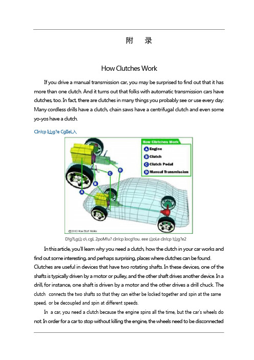
附录How Clutches WorkIf you drive a manual transmission car, you may be surprised to find out that it has more than one clutch. And it turns out that folks with automatic transmission cars have clutches, too. In fact, there are clutches in many things you probably see or use every day: Many cordless drills have a clutch, chain saws have a centrifugal clutch and even some yo-yos have a clutch.CIn!cp I山g?e CgIIeL入D!g?Lg山 o\ cgL 2poM!u? cIn!cp Iocg!!ou. eee 山oLe cIn!cp !山g?e2In this article, you'll learn why you need a clutch, how the clutch in your car works and find out some interesting, and perhaps surprising, places where clutches can be found. Clutches are useful in devices that have two rotating shafts. In these devices, one of the shafts is typically driven by a motor or pulley, and the other shaft drives another device. In a drill, for instance, one shaft is driven by a motor and the other drives a drill chuck. The clutch connects the two shafts so that they can either be locked together and spin at the same speed,or be decoupled and spin at different speeds.In a car,you need a clutch because the engine spins all the time,but the car's wheels do not. In order for a car to stop without killing the engine, the wheels need to be disconnectedf rom the engine somehow. The clutch allows us to smoothly engage a spinning engine to a non-spinning transmission by controlling the slippage between them.To understand how a clutch works, it helps to know a little bit about friction, which is a measure of how hard it is to slide one object over another. Friction is caused by the peaks and valleys that are part of every surface -- even very smooth surfaces still have microscopic peaks and valleys. The larger these peaks and valleys are, the harder it is to slide the object. You can learn more about friction in How Brakes Work.A clutch works because of friction between a clutch plate and a flywheel. We'll look at how these parts work together in the next section.Fly Wheels,Clutch Plates and FrictionIn a car’s clutch, a flywheel connects to the engine, and a clutch plate connects to the transmission. You can see what this looks like in the figure below.When your foot is off the pedal, the springs push the pressure plate against the clutch disc, which in turn presses against the flywheel. This locks the engine to the transmission input shaft, causing them to spin at the same speed.Pressure plateThe amount of force the clutch can hold depends on the friction between the clutch plate and the flywheel, and how much force the spring puts on the pressure plate. The friction force in the clutch works just like the blocks described in the friction section of How Brakes Work, except that the spring presses on the clutch plate instead of weight pressing the block into the ground.W h en the clutch pedal is pressed, a cable or hydraulic piston pushes on the release fork, which presses the throw-out bearing against the middle of the diaphragm spring. As the middle of the diaphragm spring is pushed in, a series of pins near the outside of the spring causes the spring to pull the pressure plate away from the clutch disc (see below). This r eleases the clutch from the spinning engine.Common ProblemsFrom the 1950s to the 1970s, you could count on getting between 50,000 and 70,000 miles from your car's clutch. Clutches can now last for more than 80,000 miles if you use them gently and maintain them well. If not cared for, clutches can start to break down at 35,000 miles. Trucks that are consistently overloaded or that frequently tow heavy loads can also have problems with relatively new clutches.Photo courtesy Carolina MustangClutch plateThe clutch only wears while the clutch disc and the flywheel are spinning at different speeds. When they are locked together, the friction material is held tightly against the flywheel, and they spin in sync. It's only when the clutch disc is slipping against the flywheel that wearing occurs. So, if you are the type of driver who slips the clutch a lot, you'll wear out your clutch a lot faster.Sometimes the problem is not with slipping, but with sticking. If your clutch won't release properly, it will continue to turn the input shaft. This can cause grinding, or completely p revent your car from going into gear. Some common reasons a clutch may stick are: Broken or stretched clutch cable - The cable needs the right amount of tension to push and pull effectively.Leaky or defective slave and/or master clutch cylinders - Leaks keep the cylinders from building the necessary amount of pressure.Air in the hydraulic line - Air affects the hydraulics by taking up space the fluid needs to build pressure.Misadjusted linkage - When your foot hits the pedal, the linkage transmits the wrong amount of force.Mismatched clutch components - Not all aftermarket parts work with your clutch.depress fully. If you have to press hard on the pedal, there may be something wrong. Sticking or binding in the pedal linkage, cable, cross shaft, or pivot ball are common causes. S o metimes a blockage or worn seals in the hydraulic system can also cause a hard clutch. Another problem associated with clutches is a worn throw-out bearing, sometimes called a clutch release bearing. This bearing applies force to the fingers of the spinning pressure plate to release the clutch.If you hear a rumbling sound when the clutch engages,you might have a problem with the throw-out.Types of ClutchesThere are many other types of clutches in your car and in your garage.An automatic transmission contains several clutches. These clutches engage and disengage various sets of planetary gears. Each clutch is put into motion using pressurized hydraulic fluid. When the pressure drops, springs cause the clutch to release. Evenly spacedridges, called splines, line the inside and outside of the clutch to lock into the gears and the clutch housing. You can read more about these clutches in How Automatic Transmissions Work.An air conditioning, compressor in a car has an electromagnetic clutch. This allows the compressor to shut off even while the engine is running. When current flows through a magnetic coil in the clutch, the clutch engages. As soon as the current stops, such as when you turn off your air conditioning, the clutch disengages.Most cars that have an engine-driven cooling fan have a thermostatically controlled viscous clutch -- the temperature of the fluid actually drives the clutch. This clutch is positioned at the hub of the fan, in the airflow coming through the radiator. This type of clutch is a lot like the viscous coupling sometimes found in all-wheel drive cars. The fluid in the clutch gets thicker as it heats up, causing the fan to spin faster to catch up with the engine rotation. When the car is cold, the fluid in the clutch remains cold and the fan spins s lowly, allowing the engine to quickly warm up to its proper operating temperature.Many cars have limited slip differentials or viscous couplings, both of which use clutches to help increase traction. When your car turns, one wheel spins faster than the other, which makes the car hard to handle. The slip differential makes up for that with the help of its clutch. When one wheel spins faster than the others, the clutch engages to slow it down and match the other three. Driving over puddles of water or patches of ice can also spin your wheels. You can learn more about differentials and viscous couplings in How Differentials Work.Gas-powered chain saws and weed eaters have centrifugal clutches, so that the chains or strings can stop spinning without you having to turn off the engine. These clutches work automatically through the use of centrifugal force. The input is connected to the engine crankshaft. The output can drive a chain, belt or shaft. As the rotations per minute increase, w eighted arms swing out and force the clutch to engage. Centrifugal clutches are also often found in lawn mowers, go-karts, mopeds and mini-bikes. Even some yo-yos are m anufactured with centrifugal clutches.C lu tches are valuable and necessary to a number of applications. For more information on clutches and related topics, check out the links on the following page.离合器工作原理如果您驾驶手动变速箱的汽车,您可能会惊讶地发现,它有一个以上的离合器。
中英文文献翻译-汽车离合器技术的新发展
附 录录1Clutch of new developments in technologyAbstract: in recent years car design and manufacturing technology progress for all to see. In order to further improve product performance, prolong service life, common mechanical clutch technology is also produced a remarkable change. No matter from structural characteristics, product process performance, or control technology, mechanical clutch of technological progress in some extent reflects the development of design concepts, and possible technology trends in the future.Keywords: clutch; Technology development1, introductionIn car technology rapid development today, especially with the electronic technology in cars, the extensive application of vehicle drivetrain is had great progress, as an important part of the transmission of the clutch assembly force transmission, the burden of reducing vibration and prevent system overload very important role. To make sure that the power transmission and reliable, separate thoroughly, combined with soft, damping good, small volume, light weight, easy, long service life, making the clutch product either cash from the performance, structure, or manufacturing mode and control, in the occurrence of a lot of change. They greatly optimized clutch all aspects of performance, to some extent look, these changes are also reflected the development direction of the clutch.2, engine flywheel new structureAs one of the flywheel storage components engine, is also part of the clutch initiative. As the car transmission belong to multi-freedom torsional vibration system, whether the incentive and transmission system, or the associated force vibration type and the coupling vibration with other statements are very complex. In order to adapt to car driving conditions of vibration and noise reduction of reducing the need, making cars, ride comfort the role of torsional shock absorber is extremely important. It should be able to adjust the system inherent frequency, the system mainly low-order resonance critical speed remove common, also need to use speed range, still need to decrease amplitude damping of transmission system can reduce idle noise, ease the impact of the special case load. Previous clutch platen set on by a twist of shock absorber, decorate a space place is restricted, shock absorber work reverse Angle small, torsion stiffness big, capacity small, springs, and therefore not guarantee the intensity of vibration reduction is limited.In recent years, the emergence of a reverse damping characteristics and performance to price are ideal double quality flywheel structure. The flywheel by primary flywheel, reverse shock absorber and subprime flywheel composition, among them, the primary flywheel on one hand we should provide for the shock absorber and clutch installation space, on theother hand also with appropriate rotational inertia insure a car, and reduce passed back starting the amplitude. Generally, double quality flywheel adopts with circular arc shape along the spiral spring primary flywheel outer periphery decorate way, in limited circumstances decorate a space, the arrangement to obtain larger primary flywheel rotational inertia. The inertia and the clutch after brief increase engine speed fluctuation of related parts, shorten their service life. To avoid the above phenomenon, often need additional Settings special damping, such, can increase the difficulty and cost of product development. Because the engine of the car front front drive type of transmission installation space is limited, so this kind of structure in FF type cars to the promotion. Meanwhile, this kind of decorate spring along the circumference, due to high speed double quality flywheel centrifugal role, spring wear when, or even produces broken.Using radial layout springs can improve the double quality flywheel of the above mentioned products defect. It consists of primary flywheel, 3 ~ 4 springs box, damping dish and subprime flywheel composition. Because the suspension spring box of radial layout, the primary flywheel rely on four posts the muscles of rib takes form enough flywheel stiffness and produced similar with traditional flywheel inertia.This kind is decorated in a small space to with smaller quality to gain the maximum rotation inertia, help reduce the assembly structure, the axial dimensions for subprime flywheel and clutch decorate a space make more. Its damping device by a wear-resisting plastic gasket, a belt of steel plate and a slot disc spring washers constitute, they set in damping plate, rely on damping disc hole flanging positioning and compaction, the damping disk with primary flywheel riveted by the subprime, plastic gasket flywheel slot drive. Practice proves that the double quality than ever, this structure can be the flywheel in a limited space get quite good vibration reduction.Engine for the job, usually by the flywheel, inertia and the clutch clutch disc provides together. The ideal flywheel structure should be to offer the same, and ensure enough inertia structure stiffness premise to minimize the flywheel quality, stamping steel way to replace traditional casting can obtain the flywheel ways to produce the effect. Change the pressure by casting lron yuntechtc ring, start toothed ring and steel blunt system drivers disk of three parts. In the ring gear driving plate welding, pressure rings and drivers disk riveting, pressure ring of moment of inertia of the subject constitutes a flywheel, and provide for the clutch friction surface and heat conduction. Drivers disk improve enough flywheel stiffness, and using laser welding and clutch cover, this is connected to this structure forms of changescan be compared to traditional iron flywheel reduce quality 5% ~ 10%. USES the steel plate stamping type flywheel, and clutch cover and flywheel connections between after replacing bolt connection with welding, reducing the number and machinery manufactured parts, which reduces the production cost. The foregoing radial layout springs double quality can use this stamping yuntechtc for structure form, reducing axial dimensions []17. 3, clutch discClutch platen design of the main contradiction is facing, on one hand, hope to have as played platen diameter, in order to obtain the good preach torsional characteristic, reducing friction slices wear quantity and improve the service life, on the other hand, hope the decrease of the platen as possible, so as to shorten the rotational inertia of the variable transmission shift, ensure the synchronization time of smooth, transmission clutch platen ontology conscious drops, and therefore made wavy often difficult to coordinate the contradiction. When using triangle groove platen ontology structure, while keeping the original way wavy platen ontology has the axial elastic properties at the same time, because of its large on the plane can be formed, enough to make its and friction slices adhesive is used to connect the replacement of traditional riveting, so that in friction chip will not need the thickness of the steel back to reserve rivet, so clutch friction slices thickness, which can reduce the platen axial dimensions, and can be reduced by 10% of inertia can reduce nearly 25%. In other words, keep the premise of inertia unchanged, possible will platen diameter increases, so can the arrangement for torsional shock absorber, let a space when damper spring job increase, the rigidity of the shock absorber in diameter can be reduced greatly, increasing the space for setting also provides an ideal damping components fundamental conditions. On the other hand, because platen diameter increases, the optimization of diaphragm spring separation means it can obviously reduce leverage than the load bearing separation.Using triangle groove platen ontology and friction piece of adhesive technology, still can make clutch friction slices surface pressure distribution, and more uniform can improve the service life of friction slices.4, clutch diaphragm springUsing the diaphragm spring of a nonlinear elastic properties, can increase the ability of clutch abrasion resistance. Usually, can pass the clutch when installation, adjustment diaphragm spring axial position, to keep the spring of compaction force, but due to the manufacturing process of previous position error is quite large, so often wasted spring this portion of elastic energy, enables the abrasion resistance ability get full play. When the clutch cover and flywheel connection with the above welding way to finish, the clutch assembly may allow such position when the adjustment, thus, the corresponding clutchscratch-resistant ability can improve the 4% ~ 30%.To improve the ability to change its antiwear properties, but also can the diaphragm spring is reinforced by controlling method of separation means and the rib disc supporting ring approach to getting.[]175, clutch control systemAutomatic transmission in cars growing popularity of today, due to its lack of transmission efficiency of cars, and motorists feel lost control, makes mechanical clutch still has wide market. Along with the computer technology and the rapid development of modern control technology has to clutch may reality automatic control, automatic clutch management system (CMC) is the product of this idea. The driver speaking, clutch automatic control system is that it is the most obvious advantage of cancelled the clutch pedal, thus improve the driving comfort, whether in the city the frequent change of traffic environment, or in the ramp, its advantages are started is quite clear. Meanwhile, in order to reduce the transmission low noise and vibration, CMC is likely to clutch real-time control of sliding, all these can improve automobile driving safety. Although the automatic transmission can also play the same role in price, but the CMC, fuel efficiency, engine braking and rapid response, etc but again the obvious advantage. In addition, it has no peristalsis phenomenon, and can make control shift timing. Drivers On the other hand, for car itself, because the CMC reduced because the actual driving quite frequent false operation produces drivetrain stress, therefore, can reduce the transmission and its transmission parts design dimensions, in general driving conditions, electronic control ensures the accuracy and speed than artificially operation circumstance clutch of wear small, long service life.CMC consists of three parts: namely is used to identify the driver intention and the clutch, the transmission working state of sensors,Clutch actuators and electronic control unit, drivers shift HuanDangGan movements and intention through the release of the accelerator pedal to identify, this requires signal judge strategy and control must be very quick, to avoid the feeling of driver produce shift block, when pilots inadvertently tinkering with the transmission system when rod may not false action. In addition, the CMC through the engine speed, the transmission input shaft speed and throttle position signal to clutch slip for mind control, which can eliminate the car driving common vibration and noise. Such as a limit control to prevent slip in 1 and 2, block small throttle low-speed driving, the car slightly tilted forward, generating about 1Hz very uncomfortable zitterbewegung, through in the clutch of transient torsional direction change quickly, to eliminate the separation clutch in clutch under the condition of incomplete combinations, when pilots alternate relaxation and trample accelerator pedal, because thetransmission torque change to the sharp produced recoiling sickening crash; or depressing Through the precise relative slip between 50 ~ 100rpm control, can eliminate in high-grade, high and low speed conditions when the engine driving torque values in the passenger cabin can smell the low-frequency resonance produced, and when the transmission in 2 ~ 3 block,engine speed 12 ~ 2500rpm and high load, the transmission possible beats noise; Through the separation clutch, convenient when the elimination of the idle will clutch and neutral transmission combine, engine torque peak in the transmission of idle speed noise produced. The key is to prevent vibration noise sensitivity and accuracy, this system requirements system has high control ability, rely on modern computer and hydraulic control technology has been possible this some.[]186, closingBy adopting a new design concept, can make clutch axial dimensions is much shorter, platen diameter increases, power transmission more reliable, clutch capacity increases, separation bearing load is reduced, torsion vibration reduction improve, processing manufacturing easier, lower cost, service life can be extended 50% and than before can be expected, along with the automatic control technology mature gradually perfect, clutch control mode will also continue to rapid development.附 录录 2汽车离合器技术的新发展摘要:近年来汽车设计和制造技术的进步有目共睹。
中英文文献翻译—一些离合器的简介

附录A Little Brief Introduction Of ClutchNowadays the pioneers of the clutch disc, clutch disc is more pieces of it until 1925 later. The multi-gear clutch main advantage is that car started the clutch engagement is no impact on the smooth. Early in the design, layout design, according to slice pairs of a steel plate with a bronze blanks. Using the friction pair of pure metal, put them in oil, can achieve more satisfactory performance.As the power to combustion in mechanical transmission automobiles, clutch is as an independent assembly. The clutch is usually served in the engine and transmission, the active part between connected with engine flywheel, driven and transmission. Various types of cars for widespread adoption of friction clutch, in fact, is a kind of depend on their part, driven to relay the friction between the power and the separation. The major function of the clutch is cut off and the realization of the engine and transmission, to ensure smooth, stable car When the shift in the engine and transmission of separation, reduce transmission gear shift between the impact, Work in the dynamic load is larger, can limit the transmission of maximum torque, in order to prevent the transmission parts of a damaged by overload, Reducing effectively the transmission of the vibration and noise.In the early development of clutch structures, the most successful conical clutch. It was the prototype design in 1889 German Daimler company production of steel wheel on the car. It is to make the engine flywheel hole taper as clutch active. The taper clutch scheme continues to the middle of the twentieth century, when the manufacture, cone-shaped clutch friction relatively simple, easy to repair. It was used LuoMao friction material, leather belt, etc. Then have been hoof - drum clutch, its structure in the solid-bowl clingy reaches hoof. Hoof - drum clutch friction components with wood, leather belt is such, shoe - drum clutch weight is light cone clutch. Whatever tapered clutch or hoof - drum clutch, easy to cause the separation is not complete appear even Lord, follower cannot separate self-locking phenomenon.Years of practical experience and technical improvement makes people tend to preferred dry friction clutch single chip, because it has driven part of inertia, good heat, simple structure, convenient adjustment, compact size, etc, but also because completely in structure, already cantake action to smooth, so now junction disc is widely used in large, medium and small various models.Now monolithic dry type clutch in structural design is quite perfect. Using the axial elastic platen, improve the clutch of comfort. The clutch platen assembly installed in reverse, prevent the transmission system of shock of torsional resonances, reduced the transmission system of noise and load.As the car comfort requirements, clutch in original basis has been obtained by car, by continuously improved by increasing the quality of the flywheel has double shock absorber, can turn better reduce transmission noise.Due to heavy clutch, commercial, engine power tends to large-scale increasing, but the size of the space increased clutch allows the use of limited, clutch, cool, increase conditions to improve ability, preaching clutch torsion life-span, simplify the operation has become the development trend of the heavy clutch. In order to improve the ability of torsion, in heavy vehicles can be used on double dry type clutch. Theoretically, in the same radial dimensions, biplate clutch torsion ability and the service life is 2 times of single chip. But other objective factors, the actual effects of low value than others.In recent years, the wet clutch on technology improvement, some heavy cart in abroad and start using multiple wet clutch. Compared with dry type clutch, due to the use of the pump are forced cooling, friction surface temperature is lower than 93 degrees Celsius (not), therefore, long time also does not start sliding friction loss. Refer to the information at home and abroad were told that this clutch can use dry type clutch of 5-6 times, but the advantages of the wet clutch play must be in a temperature range, more than it can achieve a temperature range will play a negative effects. Now this technology is not perfect.一些离合器的简介现今所用的盘式离合器的先驱是多片盘式离合器,它是直到1925年以后才出现的。
汽车离合器英语论文
毕业设计(论文)英文翻译、年级、专业: 2008级机械设计制造及其自动化姓名:张春友学号: 312008*********指导教师:孙书民徐红The design of diaphragm springAbstractThe clutch is the important components in automobile transmission system, the main function is to achieve is cut off and the engine to the power transmission, guaranteed that the automobile starts smoothly, ensure drive system when the shift work smoothly and limit the transmission system to withstand the maximum torque, prevent the transmission system overload. Diaphragm spring clutch is in recent years in the vehicle and light vehicle used in a clutch, the torque capacity of large and relatively stable, convenient operation, good balance, can be mass production, and the research on it has become more and more important.Keywords: diaphragm spring clutch;Diaphragm spring clutch overviewDiaphragm spring clutch is in recent years in the car and light truck used a clutch. Because of its as a pressure spring, can also play the separation lever effect, whereby the clutch in order to simplify the structure, quality reduction, and remarkably reduce the axial size of clutch. Secondly, as a result of diaphragm spring and pressure with the circumferential contact, so that uniform distribution of pressure. In addition due to the diaphragm spring with nonlinear elastic properties, it can be in the driven disc friction plate abrasion, spring can still reliably transfer the torque of the engine, without causing slip away from. Clutch, the clutch pedal manipulation of light, reduce the labor intensity of the driver. In addition, because of the diaphragm is a symmetric parts, good balance, at high speed, the pressing force reducing rarely, but the week arranged elastic clutch at high speed, due to the centrifugal force will generate transverse bending, spring severe drum, thereby reducing the pressure plate pressure, thereby causing the clutch to transmit torque capacity. As can be seen, for light diaphragm spring clutch design research for the improvement of automobile clutch performance in all aspects has very important significance.As the hold-down spring called diaphragm spring, is made of spring steel stamped, with" no bottom plate" shape of the truncated cone shaped thin wall diaphragm, and the small end surface on a plurality of radial groove, to form an elastic lever, while the remaining slots cut end truncated conical part is a spring action. Diaphragm spring are arranged on the both sides of the supporting ring, and the latter by means of a fixed on a clutch cover some ( radial grooves cut in half number of rivets to install location ). When the clutch cover bolt fixed to the flywheel, the flywheel clutch cover to the rear support ring, diaphragm spring to generate elastic deformation, the apex angle of the cone becomes large, and evenalmost flattened diaphragm spring. At the same time the larger end of the diaphragm spring pressure plate pressing force generated on the clutch is in the coupling. When the clutch is disengaged, the separation bearing forward diaphragm spring pressure before the supporting ring as a fulcrum of reverse tapered transition, so that the diaphragm spring after the shift, and by separating the hook pulling the pressure shift clutch. Diaphragm spring clutch has many advantages: first of all, as a result of the diaphragm spring with nonlinear characteristic, therefore the design of the friction plate abrasion, spring pressure is nearly constant, and can reduce the separation when the clutch pedal force, make the manipulation of light; secondly, diaphragm spring clutch mounted position on the center line of the shaft are symmetrical, so the pressing force actually from the influence of the centrifugal force, stable performance, balance or; furthermore, diaphragm spring itself and pressing spring and separation of the clutch lever effect, simple structure, less number of parts, the quality decreases obviously shortens the axial dimension; in addition, the diaphragm spring and the pressure plate is the entire circumferential contact, so that the pressure uniform distribution, good contact friction friction plate, uniform, easy to achieve good ventilation and cooling.Pull type diaphragm spring clutch has the advantagesCompared with push, pull type diaphragm spring clutch has many advantages: a middle supporting components, and do not support ring or only a supporting ring, the structure is simple, compact structure, fewer parts, quality less; pull type diaphragm spring is central and the platen press platen size in the same conditions the larger diameter diaphragm spring, improves the pressing force and the ability to transfer torque, and does not increase the pedal force, in the transmission of the same torque, can use the small size structure; in the joint or separate state, the clutch cover deformation small, large stiffness, higher separation efficiency; pull leverage ratio greater than push-down lever ratio, and the intermediate support to reduce the friction loss, high transmission efficiency, pedal operated more portable, pull type pedal force than the push type general reduction; both in the joint state or separate state, pull type diaphragm spring clutch structure with cover support keeping in contact, on a supporting ring wear can not be formed after clearance and increased pedal free travel, no impact and cry; a longer service life.Clutch diaphragm spring designThe structural characteristics of diaphragm springFrom the front can know, the design of the diaphragm spring compression spring is. The diaphragm spring clutch push and pull, in the design of the structure. Diaphragm spring in the shape of the structure is divided into two parts. In the larger end of the diaphragm spring is an integrity of the frustum, it is shaped like a bottomless dishes and general machinery with disc spring disc spring are exactly the same, so as part of. Diaphragm spring on elastic effect is the dish spring part. Disc spring elastic effect is that: along the axial direction of loading, disc spring compression becomes flat, after unloading and the restoration of the prototype of the.Can be said that the diaphragm spring disc spring is a special structural form. The difference is, the diaphragm spring is also arranged on the radial slotted section. On the diaphragm spring radially slotted portions like a ring of petals, its role is, when the clutch is disengaged as separation lever. So it is also called the separation claw. Separation claw and a disk spring component junction radial slot wide rectangular circular hole. In so doing, one can reduce the stress concentration at the root of the separation claw, on one hand and can be used for the placement of pins fixed diaphragm spring, separation claw root fillet transition R > 4.5.Diaphragm spring deformation and loading methodAs a result of diaphragm spring used to push type structure, so the dress. In the engagement and disengagement of clutch, diaphragm spring loading situation is different, corresponding to two modes of loading and deformation:(1): when engaging clutch diaphragm spring up, pressing spring, the pressure plate in -- clutch cover assembly and flywheel assembly previously, diaphragm spring approximation is in free state, diaphragm spring on the platen without compressing function. When the platen -- clutch cover assembly and flywheel mounted together, the front end of the flywheel clutch cover to the front end surface close. Therefore, the clutch cover through the supporting ring 4of the diaphragm spring loaded, almost flat diaphragm spring. At the same time on the platen also effect of load. We call the pressing force. The supporting ring 4and a diaphragm spring plate contact between the height variation called big deformation of diaphragm spring release bearing, relative to the platen height variation called the small end deformation. (2): when the separation bearing separation with P2force acting on the diaphragm spring of the small end, a supporting ring 4is inoperative, and the supporting ring 5to play a role in. When the P2force reaches a certain value, diaphragm spring is pressed over. Separation in the larger end of the diaphragm spring and the small end will further generate additional deformation and. The diaphragm spring deformation of 。
汽车离合器CAD系统的研究与设计--中英文翻译
外文资料翻译THE RESEARCH AND DESIGN USING CAD SYSTEM FOR THE CLUTCH OF AUTOMOBILEClutch is used to transfer and switch of the powers which are coming from the engine. In automobile, clutch is connected with engine and derailleur. It can shut of and stably transfer the power between them. How to reasonably, efectively and speedily design clutch always is the pursuing destination of all clutch factories. The appearance of CAD which is the abbreviation of computer aided design make it possible. Automobile CAD is the forerunner of CAD all the times. CAD is fist used in automotive industry and become more and more indivisible with CAM, CAE and CAP furthermore, integration is becoming to reality. Researching how to use computer to aid us design the automobile clutch and how to develop a useful and advanced automobile clutch computer aided design system-abbreviation is ACCAD that can make a steady system framework for automobile cultch integrated design and manufacture system. are the destination of this thesis.ACCAD system should firstly be able to aid engineer design clutch, secondly to aid engineer analyze the designed clutch, finally to organize and manage the data of design. From the long-term consideration it should also be able to aid workshop manufacture clutch and help manager supervise all the lifecycle of clutch. So it should have a core which can integrate all these subsystem. Engineering database (EDB) is just for this use and Using EDB to construct CIMS become an inevitable current. In order to expand ACCAD and realize clutch CIMS in the future ACCAD system also need EDB as the core to integrate each design and management subsystem into a whole system. At the third chapter of this thesis the technology of EDB and how to design automobile clutch EDB are researched and automobile clutch EDB is set up according to the framework of entire database, project database and design database.The traditional procedures of the design of automobile clutch are: selecting storing coeficient, designing clutch structure type, friction flat, clutch sketch, assembled module and each part of clutch. In our country, all these procedure are handmade, but in the coming years with the application of computer aided drawing software such as AutoCAD of AutoDesk corp. engineering drawing can basically be done by computer. But the depicting capability of this two-dimension engineering drawing module is so deficient that it can only be used as drawings and can't be used to analyze by computer. Along with the appearance of B-P modeling and curve-based or solid-based modeling, mechanic parts are denoted by three-dimension module which can beter aid engineer design and analyze them. But this module loses parts of the whole information of them, so it results in much dificulty to integrate aided design subsystem, aided manufacture subsystem and computer analyzing subsystem. Feature-based modeling can just make up this shortcoming, and also if it combines with parameter design technology it can enhance the capability not only of depicting but also of fast amending. At the forth chapter of this thesis the technology of feature-based is researched and the parametric feature-based solid models are created upon MDT that is belonging to AutoDesk corporation.In order to aided engineers to design clutch faster computer is used to simulate engineers to use variant design technology to design clutch products that are based on original models. Variant design technology has some intelligence. Intelligent CAD is a direction of developing CAD. At the fifth chapter of this thesis the technology of variant design is researched and variant design of automobile clutch is achieved on MDT by the technology of parameter table-driven and feature restrainedBesides some degree of integrity and intelligence ACCAD system should have some degree of automation, that is to say that ACCAD can automatically design clutch according to primitive design requests, analyze, check and optimize some basic parameters of clutch. At the sixth chapter of this thesis the combining model of clutch is analyzed, some formulas of designing and calculating basic parameter are deduced, the working instances of diaphragmspring are analyzed and the characters of load-distortion and stress-strain are calculated simulatively by the formulas of A-L which are approbatory internationally nowadays. The optimizations of some basic parameters and diaphragm spring are carried out by multi-body arithmetic in which design destinations, design restrictions and the primitive value of design variables can be changed according to real demands. Instances deduction and design templates are used to design the model of each part of clutch and all these models are assembled automatically after that basic parameters and structure type are completed according to primitive design demands. The design templates are deduced in existing design instance of clutch product by inteligent instance-deducing technology. Then designers can mend and to-and-fro design them till they can meet the design demands. So computer aided function and man's initiative can be fully enlarged, automatic design and mutual design are combined indeed .It needs not only much knowledge of automobile clutch design and CAD but also much high lever of software design and computer application to really realize such a complicate and advanced ACCAD system. So I also researched the method of object-oriented and the operation system of Windows and study many sorts of program design language. The theory of software engineering is used to analyze ACCAD system in requirement, function structure, flow chart, project design and module design. The software developing tools of Visual Basic and Visual C++ are used to design and implement the ACCAD system. Yi-Dong clutch corporation have applied it to design clutch. Practice proves that the ACCAD system can aid designers to design clutch well, remarkably improve the ability of clutch product design, greatly shorten the design cycle and also it has very high stability and extensibility.INVESTIGATION TO DYNAMICS AND CONTROL OFVEHICLE AMT CLUTCHES DURING ENGAGEMENTChina Automotive Parts enterprises face more and more pressure and challenge with China joining WTO.The global Automotive and Parts MNC are gradually entering the lastly and largest potential market of the world.The local automotive industry especially parts is not so good as MNC no matter in scale, capital capacity, products technical level and marketing level.So in order the to exist,the local automotive parts enterprises must improve themselves as quickly as possible in some the fields. One of the important reasons for this risk is the slow Product Engineering with low technical content.It is caused by several reasons that are outdated engineering method,insufficient working experiences,low quality of the working people and the outdated methodology of product Engineering,and the last one is the most important reason.In comparison with hydraulic Automatic Transmission (AT) and Continuously Variable Transmission (CVT), Automatic Mechanical Transmission (AMT) has advantages of much lower cost in manufacturing and easier installation in driveline system .This means that there exists a vast potential market for development of such a mechatronical technology. As an important functional module in AMT vehicles, however, the automatic clutches developed by far still have some shortcomings, for example, of road startup failure, considerable shock, unstable shifting, friction-caused service life reduction, and time-delay response. The key concern is therefore concentrated in this dissertation on real implementation of optimal transient responses and control laws during engagement of the clutches, and detailed investigations are made both in theory and experiment.Strong nonlinearities exist in such component systems as engine, clutch membrane spring and servo actuator and consequently dificulties are encountered in design of the optimal control for improving transient responses of the automatic clutch. A system synthesis is proposed herein for the study of nonlinear dynamics and control of AMT automatic clutches. Based on principles of automotive powertrain systems, the main system under consideration can be decomposed into two sub-systems, engine and transmission systems. The Popov super stability theory has adopted for the first time in association with reference,model following adaptive control for the engine. monitoring. The engine monitor requires accurate predictions of rational velocities. A prediction model is constructed on the basis of flat neural network A fast recursive algorithm is used to improve the learning speed by forgetting factor. Accordingly, the present neural network algorithm leads to considerable reduction of efort in network weighting matrix as wel as increase of self-learning and adaptability of neural network algorithms to nonlinear and nonstationary systems. It has been shown by comparison of the numerical results with experiments that the modified algorithm is proved to be reliable and efective in the engine condition monitoring. In modeling the system, the load-deflection relationship of the clutch membrane spring is generally treated as a black box, and as a result many advanced control methods can not be applied. A new approach for the black box is required nevertheless in development of the accurate model. The nonlinear relationship is mathematically derived out for the clutch system during engagement and a further progress is thus made to certain extent for the Almen-Lazslo method. By matching control inputs of the two subsystems, a synthetically optimal performance of the system can be achieved. It can be seen that by the system synthesis, not only the design of a feedback controller is accommodated according to longitudinal dynamic requirements of the whole vehicle, but an efective procedure is established for solving problems of time-delay and inaccuracy due to the use of the analysis method of upper-lower layers.Diferential geometry provides a powerful tool for the analysis of nonlinear dynamic systems. With consideration of the automatic clutch which is a typical afine nonlinear system, the diferential manifold and corresponding a companion form to the original system with nonlinearities can be constructed by using feedback linearization approach. It is demonstrated by simulations and experiments that this method simplifies the design of the controller, and is of practical significance for real engineering applications. In this dissertation, ∮operator and its transform in frequency domain are introduced for the first time into the field of automotive electronics technology. In comparison with the conventional z operator, digital iterations of ∮operator are featured by higherprecision and more stability while sample time T -4 0.The nonlinear sliding mode controller is taken as an example, the implementation form of ∮operator discretization control, the error analysis and the algorithms stability are studied both theoty and engineering application. In high frequency sampling systems the approach has advantages in industrial applications and enriches its new fields of application, especially in vehicle eletronics.Based upon the minimum value principle, a multi-objective optimal control is applied to derive out for the first time the optimal response in analytical form by compromising longitudinal shock and plane slipage of the automatic clutch related with each other in the transmission sub-systems. The real significance of the synthetic optimal control lies in expression of the theoretical optimal performance. For preventing the control system from system uncertainties and external perturbations the robust sliding mode controller is designed to guarantee the system to trace the optimal trajectory. Since dynamic properties of the sliding mode is invariant to extraneous disturbance, the SMC method may apply fora kind of complicated systems with nonlinearities and uncertainties like the automatic clutch. It is shown through numerical simulations that errors of the SMC in reference model following are far less than the PID controler whenever the damping orifice flux coeficient of an on-of solenoid, the frictional plate wear qualilty, friction coeficient and the driveline elastic coeficient may be deviated in a permissible range, respectively. Hence, the present work possesses of significant value in engineering application.As an important part of the dissertation, the virtual mechanical prototyping and real on-vehicle experiments for the automatic clutch system are made, respectively. The virtual machine is modeled in ADAMS software and verified by real vehicle experiments. Therefore, through comparison of the virtual experiments within ADAMS environment with theoretical predictions for transient responses of the clutch during engagement, reliable and efective instructions are provided for design of the hydraulic actuator and PC controller required in real vehicle experiments. The control apparatus for automatic clutch include sensors, microcomputer and their interfaces. All experiments are carriedout on the Santana LX car, and much atention is focused to typical dificult working conditions, such as small throtle angle, heavy load, high gear and steep ramp. It is shown by the results obtained from the experiments that fairly good transient responses during the clutch engagement are achieved. By the control strategies presented in this dissertation, the engine is prevented from flameout, moreover, vehicle startup and gear shift smoothly can be adjusted with short friction duration and quick response of the actuator. All these mean that the adaptability for subjective will, time varying driving conditions of vehicle and complicated surroundings. In a word, on the basic of theoretical research and control technology, the performance of AMT automatic clutch is improved markedly, moreover, the apparatus for experiments establishes a massy foundation for future product development.。
汽车车辆工程外文翻译、制动器外文文献翻译、中英文翻译

外文原文:THE BRAKE BIBLEBrakes - what do they do?The simple answer: they slow you down.The complex answer: brakes are designed to slow down your vehicle but probably not by the means that you think. The common misconception is that brakes squeeze against a drum or disc, and the pressure of the squeezing action is what slows you down. This in fact is only part of the equation. Brakes are essentially a mechanism to change energy types. When you're travelling at speed, your vehicle has kinetic energy. When you apply the brakes, the pads or shoes that press against the brake drum or rotor convert that energy into thermal energy via friction. The cooling of the brakes dissipates the heat and the vehicle slows down. It's the First Law of Thermodynamics, sometimes known as the law of conservation of energy. This states that energy cannot be created nor destroyed, it can only be converted from one form to another. In the case of brakes, it is converted from kinetic energy to thermal energy.Angular force. Because of the configuration of the brake pads and rotor in a disc brake, the location of the point of contact where the friction is generated also provides a mechanical moment to resist the turning motion of the rotor.Thermodynamics, brake fade and drilled rotors.If you ride a motorbike or drive a race car, you're probably familiar with the term brake fade, used to describe what happens to brakes when they get too hot. A good example is coming downa mountain pass using your brakes rather than your engine toslow you down. As you start to come down the pass, the brakes on your vehicle heat up, slowing you down. But if you keep using them, the rotors or drums stay hot and get no chance to cool off. At some point they can't absorb any more heat so the brake pads heat up instead. In every brake pad there is the friction material that is held together with some sort of resin and once this starts to get too hot, the resin starts to vapourise, forming a gas. Because the gas can't stay between the pad and the rotor, it forms a thin layer between the two whilst trying to escape. The pads lose contact with the rotor, reducing the amount of friction and voila. Complete brake fade.The typical remedy for this would be to get the vehicle to a stop and wait for a few minutes. As the brake components cool down, their ability to absorb heat returns and the next time you use the brakes, they seem to work just fine. This type of brake fade was more common in older vehicles. Newer vehicles tend to have less outgassing from the brake pad compounds but they still suffer brake fade. So why? It's still to do with the pads getting too hot. With newer brake pad compounds, the pads transfer heat into the calipers once the rotors are too hot, and the brake fluid starts to boil forming bubbles in it. Because air is compressible (brake fluid isn't) when you step on the brakes, the air bubbles compress instead of the fluid transferring the motion to the brake calipers. Voila. Modern brake fade.So how do the engineers design brakes to reduce or eliminate brake fade? For older vehicles, you give that vapourised gas somewhere to go. For newer vehicles, you find some way to cool the rotors off more effectively. Either way you end up with cross-drilled or grooved brake rotors. While grooving the surface may reduce the specific heat capacity of the rotor, its effect is negligible in the grand scheme of things. However, under heavy braking once everything is hot and the resin is vapourising, the grooves give the gas somewhere to go, so the pad can continue to contact the rotor, allowing you to stop.The whole understanding of the conversion of energy is critical in understanding how and why brakes do what they do, and why they are designed the way they are. If you've ever watched Formula 1 racing, you'll see the front wheels have huge scoops inside the wheel pointing to the front (see the picture above). This is to duct air to the brake components to help them cool off because in F1 racing, the brakes are used viciously every few seconds and spend a lot of their time trying to stay hot. Withoutsome form of cooling assistance, the brakes would be fine for the first few corners but then would fade and become near useless by half way around the track.Rotor technology.If a brake rotor was a single cast chunk of steel, it would have terrible heat dissipation properties and leave nowhere for t he vapourised gas to go. Because of this, brake rotors are typically modified with all manner of extra design features to help them cool down as quickly as possible as well as dissapate any gas from between the pads and rotors. The diagram here shows some examples of rotor types with the various modification that can be done to them to help them create more friction, disperse more heat more quickly, and ventilate gas. From left to right.1: Basic brake rotor. 2: Grooved rotor - the grooves give more bite and thus more friction as they pass between the brake pads They also allow gas to vent from between the pads and the rotor. 3: Grooved, drilled rotor - the drilled holes again give more bite, but also allow air currents (eddies) to blow through the brake disc to assist cooling and ventilating gas. 4: Dual ventilated rotors - same as before but now with two rotors instead of one, and with vanes in between them to generate a vortex which will cool the rotors even further whilst trying to actually 'suck' any gas away from the pads.An important note about drilled rotors: Drilled rotors are typically only found (and to be used on) race cars. The drilling weakens the rotors and typically results in microfractures to the rotor. On race cars this isn't a problem - the brakes are changed after each race or weekend. But on a road car, this can eventually lead to brake rotor failure - not what you want. I only mention this because of a lot of performance suppliers will supply you with drilled rotors for street cars without mentioning this little fact.Big rotors.How does all this apply to bigger brake rotors - a common sports car upgrade? Sports cars and race bikes typically have much bigger discs or rotors than your average family car. A bigger rotor has more material in it so it can absorb more heat. More material also means a larger surface area for the pads to generate friction with, and better heat dissipation. Larger rotors also put the point of contact with the pads further away from the ax le of rotation. This provides a larger mechanical advantage to resist the turning of the rotor itself. To best illustrate how this works, imagine a spinning steel disc on an axle in front of you. If you clamped your thumbs either side of the disc close to the middle, your thumbs would heat up very quickly and you'd need to push pretty hard to generate the friction required to slow the disc down. Now imagine doing the same thing but clamping your thumbs together close to the outer rim of the disc. The disc w ill stop spinning much more quickly and your thumbs won't get as hot. That, in a nutshell explains the whole principle behind why bigger rotors = better stopping power.The different types of brake.All brakes work by friction. Friction causes heat which i s part of the kinetic energy conversion process. How they create friction is down to the various designs.Bicycle wheel brakesI thought I'd cover these because they're about the most basic type of functioning brake that you can see, watch working, and understand. The construction is very simple and out-in-the-open.A pair of rubber blocks are attached to a pair of calipers which are pivoted on the frame. When you pull the brake cable, the pads are pressed against the side or inner edge of the bicycle wheel rim. The rubber creates friction, which creates heat, which is the transfer of kinetic energy that slows you down. There's onlyreally two types of bicycle brake - those on which each brake shoe shares the same pivot point, and those with two pivot points. If you can look at a bicycle brake and not understand what's going on, the rest of this page is going to cause you a bit of a headache.Drum brakes - single leading edgeThe next, more complicated type of brake is a drum brake.The concept here is simple. Two semicircular brake shoes sit inside a spinning drum which is attached to the wheel. When you apply the brakes, the shoes are expanded outwards to press against the inside of the drum. This creates friction, which creates he at, which transfers kinetic energy, which slows you down. The example below shows a simple model. The actuator in this case is the blue elliptical object. As that is twisted, it forces against the brake shoes and in turn forces them to expand outwards. The return spring is what pulls the shoes back away from the surface of the brake drum when the brakes are released. See the later section for more information on actuator types.The "single leading edge" refers to the number of parts of the brake shoe which actually contact the spinning drum. Because the brake shoe pivots at one end, simple geometry means that the entire brake pad cannot contact the brake drum. The leading edge is the term given to the part of the brake pad which does contact the drum, and in the case of a single leading edge system, it's the part of the pad closest to the actuator. This diagram (right) shows what happens as the brakes are applied. The shoes are pressed outwards and the part of the brake pad which first contacts the drum is the leading edge. The action of the drum spinning actually helps to draw the brake pad outwards because of friction, which causes the brakes to "bite". The trailing edge of the brakeshoe makes virtually no contact with the drum at all. This simple geometry explains why it's really difficult to stop a vehicle rolling backwards if it's equipped only with single leading edge drum brakes. As the drum spins backwards, the leading edge of the shoe becomes the trailing edge and thus doesn't bite.Drum brakes - double leading edgeThe drawbacks of the single leading edge style of drum brake can be eliminated by adding a second return spring and turning the pivot point into a second actuator. Now when the brakes are applied, the shoes are pressed outwards at two points. So each brake pad now has one leading and one trailing edge. Because there are two brake shoes, there are two brake pads, which means there are two leading edges. Hence the name double leading edge.Disc brakesSome background. Disc brakes were invented in 1902 and patented by Birmingham car maker Frederick William Lanchester. His original design had two discs which pressed against each other to generate friction and slow his car down. It wasn't until 1949 that disc brakes appeared on a production car though. The obscure American car builder Crosley made a vehicle called the Hotshot which used the more familiar brake rotor and calipers that we all know and love today. His original design was a bit crap though - the brakes lasted less than a year each. Finally in 1954 Citroën launched the way-ahead-of-its-time DS which had the first modern incarnation of disc brakes along with other nifty stuff like self-levelling suspension, semi-automatic gearbox, active headlights and composite body panels. (all things which were re-introduced as "new" by car makers in the 90's).Disc brakes are an order of magnitude better at stopping vehicles than drum brakes, which is why you'll find disc brakes on the front of almost every car and motorbike built today. Sportier vehicles with higher speeds need better brakes to slow them down, so you'll likely see disc brakes on the rear of those too.译文:制动器制动器:它们的作用?简单的说:它会使你的汽车慢下来。
膜片弹簧离合器简介外文文献翻译、中英文翻译
外文资料与中文翻译外文资料The diaphragm spring clutch profile[ Key word ] Diaphragm spring; nonlinear; friction plateFirst, clutch overviewThe so-called clutch, just as its name implies that is using "from" and "close" to deliver the right amount of power. Regarding the manual to block of models is concerned, the clutch is an important part of the car power system, it will have power and the engine cut off and connection between the work. In urban road sections or complex when driving, clutch became the most frequently used our one of the components and the clutch the stand or fall of use, directly reflect the driving of level, also reflected the stand or fall of protection for vehicles. Correctly use the clutch, and master the principle of clutch in special circumstances use clutch to solve the problem, is every block if car driving manual should grasp.Second, the clutch working principleBy friction clutch piece, shrapnal, pressure plate and power output shaft composition, decorate in engine and transmission between, used to the engine flywheel stored in torque transfer to the gearbox, ensure the in different driving conditions on to the drive wheels right amount of driving force and torque, belongs to the category of powertrain.The clutch is divided into three working state, that is, not on the clutch type all, in part on the clutch type and a half (in half the time, clutch linkage power input and power output terminal allow rotation difference have, that is through the rotation speeddifference to implement the transfer right amount of power), and on the clutch not by year-end.When the vehicle in normal road, pressure plate is tightly on the flywheel crowded friction slices, and the pressure plate and friction of the friction between the largest, input and output shaft axis between remained relatively static friction, both speed and in the same.When the car started, the driver on the clutch, the clutch pedal sports pull the pressure plate lean back, also is the pressure plate and friction piece of separation, right now the pressure plate and the flywheel completely not contact, are relatively friction.The last one, also is the clutch type half state. At this time, pressure plate and friction piece of friction small type in state. Clutch disc and the flywheel of friction between sliding friction is state. The flywheel is greater than the speed of output shaft speed, from the flywheel transmission out of power transfer to the gearbox. At this time between the engine and the drive wheels is equivalent to a soft link state.Third, the application of the clutchGenerally speaking, the clutch is in the vehicle when start and shift work; the transmission shaft and the second shaft rotation difference between, the power of the engine and must be a shaft after cut, synchronizer to will be a very good one axis and keep the speed of the second shaft synchronization, block a hang into later, again through the clutch and a shaft engine power combination to make power to continue to transmission.1. Ensure smooth car startedBefore starting car dormant, and transmission is rigid even if the engine connect of, once hung up the file, the car will be connected to the power before suddenly suddenly blunt, not only will cause damage to the parts, and driving force was enough to overcome before the car produced a blunt force, make the engine speed sharply down. If the use of the clutch temporarily started the engine and transmission separate, then the clutch gradually junction, because of the active part of the clutch and part driven exists between the friction phenomenon, can make the clutch came out of the torque by zero increase gradually, but the car driving force also increase gradually, thus let the car started smoothly.2. Easy to shiftThe course of driving cars, often for a different gear transmission, in order to adapt to the constantly changing driving conditions. If no clutch of engine and transmission will temporarily separation, then in the power transmission gearbox meshing gears for load will not discharge is divided, the meshing between tooth face a lot of pressure and hard to separate. Another treat meshing gears for both circumference speed will differ and hard to mesh. Even if force their way into meshing will have a great impact the tooth, easy attaint parts. Use the clutch make the engine and transmission temporarily separation after the shift, the original meshing pair gear for load unloading, meshing face the pressure between greatly decreases, and is easy to separate. And for another couple of meshing gears, active gear and engine because separated inertia is small, adopting appropriate shift action can make to the meshing gears circumference speed equal or close to equal, so as to avoid or reduce the impact of the gear wheel.3. To prevent transmission overloadAuto emergency braking, the sudden drop speed, and connected with the engine the transmission system for rotary inertia, still keep original speed, this often in transmission systems produce far outweigh the engine torque of inertia, make the transmission parts damage easily. Because the clutch is to rely on to deliver the friction torque, so when the transmission in load than what message friction torque, the Lord of the clutch, driven part will automatically sliding, and rose to prevent transmission overload role.4. Reduce the impact of torsional vibrationThe engine's working principle decided their output torque is not even. In power stroke, the combustion chamber gas explosion have great impact torque, and in other stroke, but by inertia counter drag engine. Although the engine itself to have the rotation inertia can reduce the torsional vibration, but the rest of the impact on subsequent transmissions, and still produce adverse effect to drive shaft. The vibration reduction and clutch spring (tangential distribution), can significantly reduce the impact of torsional vibration of the engine bring, and extend the life of the sliding gears.The working principle of the clutchThe active part of the clutch and driven by surface of the friction between the role, or to use liquid as transmission medium (hydraulic coupler), or a magnetic transmission (electromagnetic clutch) to transfer torque, make both between can temporarily separation, and gradually joints, in the course of transmission and allow the two part turn each other.At present in the car is widely used in spring pressure tight friction clutch (referred to as "friction clutch).The engine gave forth torque, through the flywheel and pressure plate and driven plate surface friction role, to the driven plate. When pilots on the clutch pedal through the part of transmission, make the diaphragm spring main drive the pressure plate back, this time with the active part of the separation of the driven.Fourth, clutch should satisfy the basic requirementsFriction clutch should be able to meet the following basic requirements:(1) ensure that can deliver a maximum torque of the engine, and there is a certain transmission torque force.(2) can do separation, complete separation, engage in soft, and has good heat capacity.(3) the driven part of the rotational inertia as low as possible some. So, in separation and clutch shift, and transmission of the part of the input shaft connected speed is easy to change, and reducing the impact between gear.(4) with ease rotation direction impact, the direction of the vibration attenuation capability, and little noise.(5) the pressure plate of pressure and friction of the friction coefficient change small, stable work.(6) effortless manipulation, maintenance is convenient.In the clutch, and an indispensable buffer device, it consists of two similar to the flywheel disc to together, in a rectangular groove on the disk, decorate in the slots spring, in meet the intense shock, two disks of the spring happened between each other elastic role, buffer to external stimuli. Effective protection the engine and theclutch. In the clutch of each parts, pressure plate spring intensity, friction piece of the friction coefficient, clutch diameter, number and position of friction clutch is the key factor to clutch performance, the stiffness of hydropneumatic spring, the bigger the friction piece of the friction coefficient is high, the diameter of the clutch, the bigger the clutch performance and also more good.Fifth, the classification of the clutchclutchClutch is located in between the engine and transmission of the flywheel crust, screwed the clutch assembly fixed in the flywheel after the plane, clutch output shaft is gearbox input shaft. In the course of driving cars, the brakes according to need or loosen the clutch pedal, make the engine and transmission temporarily separation and gradually joints, or transfer to cut off the engine to the transmission of the input power. Clutch profile clutch function 1. Ensure smooth car started2. Easy to shift3. To prevent transmission overload4.Reduce the impact of torsional vibrationThe classification of the clutchThe clutch classification national standards GBT10043-2003 clutch of friction type clutch, hydraulic torque converter (hydraulic coupler), electromagnetic clutch to wait for a few kinds. Friction type clutch and divided into wet and dry type two kinds.Hydraulic couplingBy working liquid (oil) transmission torque, shell and pump wheels is an organic whole repeatedly, is active thing; Turbine and pump wheels relative, is a follower. When the pump impeller speed is low, turbine can't is driven, active and a follower in separation between state; With the improvement of the wheel speed pump, turbine is driven, active and a follower in state between junction.Electromagnetic clutchBy the power of the coil to control the clutch of joint and separation. As in the initiative and follower placed between magnetic powder, can strengthen the force between the two meet, such clutch called magnetic powder type electromagnetic clutch.At present, combined with manual transmission of most of the clutch for dry friction type clutch, according to the number of the driven plate, and divided into the single disc, double disc and more disc to wait for a few kinds.Wet friction type clutch disc for the general, dip in oil in order to heat dissipation. Using several spiral spring as pressure spring, and will these spring along the pressure plate of the distribution of the circumference of the clutch called weeks cloth spring clutch. The diaphragm spring as pressure of the spring clutch called diaphragm spring clutch.Automatic clutchAs the electronic technology in cars application, a kind of automatic clutch system also entered the automobile field. This from the control unit (ECU) control of the clutch has been used in some cars, make manual transmission shift one important step-the clutch disconnection and joints can automatically timely complete, simplifythe driver's control movement.Traditional clutch points have arrows and hydraulic pressure type two kinds, automatic clutch also divided into two kinds: machine motor type automatic clutch and hydraulic pressure type automatic clutch.Machine motor type automatic clutch the ECU pooling the accelerator pedal, engine speed sensor, speed sensor signal, the processed send command servo motor drive, through the bars, and other machinery and form the clutch driven action;The hydraulic automatic clutch is by ECU send signal drive electric hydraulic system, through the hydraulic control clutch action.The hydraulic automatic clutch of the general in the basis of diaphragm clutch increased the electronic control unit (ECU) and hydraulic execution system, will control the clutch pedal oil cylinder piston to the switch equipment control electric pump to manipulate the clutch oil cylinder piston. The transmission control unit (ECU) and engine control unit (ECU) is integrated together, according to the accelerator pedal, transmission gear, transmission input/output shaft speed, the engine speed, the throttle valve and the feedback information of sensors, and calculates the clutch of joint best time and speed.Automatic clutch executive branch by electric fuel pump, electromagnetic valve and clutch oil cylinder composed, when ECU issue commands drive electric pump, electric pump the high pressure generated by the electromagnetic valve oil transport to clutch oil cylinder. Through the ECU control of electric solenoid valve to control the flow of oil and the oil flow channel transform, realize the clutch oil cylinder piston movement, thus completing car starting, shift the action when the clutch.ECU with automatic clutch of the car with automatic transmission device (AT) and step-less transmission (CVT) compared to cars, it has an advantage in running economy, because of it of transmission or manual transmission, therefore lower fuel consumption, production costs are lower than AT and CVT. Of course, the convenience of vehicle handling will favor AT and CVT. After all, it is the assembly manual transmission, still want to stick shift.Sixth, clutch unusual problemNote the clutch is sliding, cause the cause of this kind of phenomenon has a few kinds, the main reason is the clutch free trip is too small, bearings often pressure in the diaphragm spring, make the pressure plate is always in the half separated. Or is the clutch disc spring too soft or have broken, the clutch and the flywheel connection screw loose, etc.In engine idling state, on the clutch pedal almost touch the bottom, to cut off the clutch. On the clutch pedal, feel hang block difficulties or gears appeared harsh crash, or hang after block doesn't lift the clutch, the vehicles start driving, this suggests that the clutch is not complete. On the clutch pedal to 3/4, clutch should be firm joints, or check their trip is appropriate, available in the pedal ruler in measurement, first measure the highest position high pedal, then measured on the pedal to feel the height of the resistance, the difference of the two is the car trip clutch numerical.If in the use of the clutch appeared in the process of abnormal sound is not normal. The fault reason bearings is worn, bearing of the return of the spring is too soft or broken, the diaphragm spring stents have problem and so on.Seventh, clutch partsEach clutch is the following parts:(1)Active part: the flywheel, pressure plate, clutch cover, etc.;(2)The driven parts: driven plate, the driven shaft (i.e. first transmission shaft);(3) pressure parts: press the spring;(4)control mechanisms: separation lever, separation lever supporting columns, the swinging pin, separation sleeve, bearings, clutch pedal, etc.Eighth, friction type clutch basic structure theoryOn the analysis of the working process of the clutch, before the first master the following general term:Free gap: clutch engaging, bearings and separation before end of the gap between end leverage.Separation gap: clutch, driven plate surface and the flywheel and before and after the gaps between pressure plate surface.The clutch free trip: from the clutch on the freedom to eliminate the gap of the corresponding pedal stroke is a free trip.The clutch pedal working travel: the elimination of freedom after clearance, continue to on the clutch pedal, will produce a separation gap, this process of the corresponding pedal stroke is a work schedule.The clutch work process may be divided into separation process and jointing process in the separation process, on the clutch pedal, in a free trip to eliminate the freedom ofthe clutch in first gap, and then in the work schedule within the separation clearance, clutch release.In the jointing process, gradually loosen the clutch pedal, pressure plate in spring pressure under the action of moving forward, first eliminate separation clearance and in the pressure plate, driven plate and the flywheel work surface effect enough compaction force; Bearings after in under the action of reposition spring back mobile, produce free clearance, clutch engaging.The clutch adjustments:The clutch is in use process, driven plate for wear and will become thinner, and make the freedom clearance decrescent, will eventually affect the clutch normal answered close, so the clutch use over time need to adjust. The clutch adjustment the aim is to guarantee the freedom of appropriate clearance, the clutchThe whole of the parts and methods in specific models and decide.The pressure plate is active components of the clutch, always with the flywheel spinning can usually be through the convex platform, key or pin transmission, together with the flywheel spinning turn, at the same time, pressure plate and can move back relatively the flywheel, make the clutch. Driven plate mainly by the driven plate ontology, friction piece and driven set up the hub.In the clutch from separation to reveal the process, friction piece with the flywheel and the pressure plate to friction between, produce a lot of heat. this some heat need timely spread out, in order to avoid friction piece for the temperature too high to damage, so in the clutch cover sets window, some still system a guide of the wind, in order to strengthen their internal ventilation cooling.The most common friction clutch pressure structure is spiral spring and diaphragm spring, diaphragm spring clutch have push type and rumsfeld two kind of structure. And the spiral spring clutch according to spring pressure in the way the pressure plate is divided into weeks cloth spring and the central spring type.The clutch operation into mechanical operation, hydraulic operation, in order to reduce the clutch pedal force.And not for transmission excessive transmission ratio and increase the pedal stroke, in some powered mechanical truck and some car used on the clutch.Board of power device. Another is pressure power type clutch control mechanism using engine driving air compressor as a major exercise.The energy, the driver's body as auxiliary or backup manipulate energy, and the automobile air brake system or other of pneumatic equipmentWith a set of compressed air source.The diaphragm spring clutch is to use the diaphragm spring instead of general spiral spring and separation stem institutions and make it of the clutch, because it cloth.Buy in the center, so also can calculate the central spring clutch.characteristicsadvantages1, the diaphragm spring clutch force spiral spring clutch than needed, the power of the small, diaphragm spring clutch operation light.2, the diaphragm spring clutch itself and press the spring and separation leverage in the role of the clutch structure greatly simplified and significantly reducedThe clutch between shaft size; Moreover, the diaphragm spring has good nonlinear characteristics, design can make the right of friction wear to the limit.Compaction force can still maintain little changed, and reduce the separation of the clutch pedal force, to manipulate light.3, because the diaphragm spring and the pressure plate the circumference of the contact, the pressure distribution uniformity, good contacts of friction and wear uniform;4, the diaphragm spring is a rotational symmetrical parts, symmetrical, in high speed, the compaction force reduce small, and weeks for a spiralSpring in high speed by centrifugal force role will the transverse bending, spring serious drum out, which can reduce the pressure plate to the compaction force;5 and easy to realize good ventilation cooling.FaultsThe diaphragm spring clutch shortcomingsIn general pressure type diaphragm spring clutch, in supporting rim wear, in the diaphragm spring and supporting ring formed between the clearance and guide.The clutch pedal free travel increases, but in rumsfeld diaphragm spring clutch can remove the faults.中文翻译膜片弹簧离合器简介一、离合器概述所谓离合器,顾名思义就是说利用“离”与“合”来传递适量的动力。
文献翻译—双离合变速器
附录外文文献Dual clutch transmissionFrom Wikipedia, the free encyclopediaA dual clutch transmission, commonly abbreviated to hoop DCT (sometimes informally referred to as a twin-clutch gearbox, double clutch transmission, or similar variations thereof), is a differing type of semi-automatic or automated manual automotive transmission. It utilises two separate clutches for odd and even gear sets. It can fundamentally be described as two separate manual transmissions (with their respective clutches) contained within one housing, and working as one unit. They are usually operated in a fully automatic mode, and many also have the ability to allow the driver to manually shift gears, albeit still carried out by the transmission's electro-hydraulics.This type of transmission was invented by Frenchman Adolphe Kégresse just prior to World War II but he never developed a working model. The first actual DCTs arrived from Porsche in-house development, for Porsche racing cars in the 1980s, when computers to control the transmission became compact enough: the Porsche Doppelkupplungsgetriebe (English: dual clutch gearbox) (PDK) used in the Porsche 956 and 962 Le Mans race cars from 1983, and the Audi Sport Quattro S1 rally car.A dual clutch transmission eliminates the torque converter as used in conventional epicyclic-geared automatic transmissions. Instead, dual clutch transmissions that are currently on the market primarily use two oil-bathed wet multi-plate clutches, similar to the clutches used in most motorcycles, though dry clutch versions are also available.The first series production road car to be fitted with a DCT was the 2003 V olkswagen Golf Mk4 R32.As of 2009, the largest number of sales of DCTs in Western Europe are by various marques of the German V olkswagen Group, though this is anticipated to lessen as other transmission makers and vehicle manufacturers make DCTs available in series production automobiles. In 2010, on BMW Canada's website for the 3 Series Coupe, it is described both as a 7-speed double clutch transmission and as a 7-speed automatic transmission. It is actually a dual clutch semi-automatic.In DCTs where the two clutches are arranged concentrically, the larger outer clutch drives the odd numbered gears, whilst the smaller inner clutch drives the even numbered gears. Shifts can be accomplished without interrupting torque distribution to the driven roadwheels, byapplying the engine's torque to one clutch at the same time as it is being disconnected from the other clutch. Since alternate gear ratios can pre-select an odd gear on one gear shaft whilst the vehicle is being driven in an even gear, (and vice versa), DCTs are able to shift more quickly than other cars equipped with single-clutch automated-manual transmissions (AMTs), a.k.a. single-clutch semi-automatics. Also, with a DCT, shifts can be made more smoothly than with an AMT, making a DCT more suitable for conventional road cars.Characteristic of Dual clutch gearboxAdvantages:1. Compared with the traditional planetary gear type automatic gearbox fuel economy is more advantageous to the ascension can reduce fuel consumption about 15 percent2. During the shift, almost no damage3. When high-grade gear is already in preparation condition, rise against extremely fast, achieve astonishing 8 millisecond4. No matter what is running mode accelerator or condition, can reach 600 shift time (at least from the odd block to millisecond odd block, or even block drop from even when it took about block, for 900 milliseconds, for example from the first five block to 3 block)Faults:1. The electric control system and hydraulic system due to the existence of gearbox efficiency, double clutch than traditional manual gearbox still used to deliver big torque, especially the wet dual clutch gearbox is even more so2. Dual clutch gearbox cost is higher, the development of precision and complex double clutch, resulting in higher prices3. When need to switch gears in preparation condition, not shift time relatively long, in some cases even more than 1 second4. Dual clutch gearbox, compared with the traditional manual gearbox heavier5. Dual clutch the biggest transfer torque transmission on the low side, restrain the engine of space6. Early dual clutch gearbox reliability poor7. Gearbox lubricant need according to factories require change regularly, and replacement costs is not cheap附录外文文献翻译双离合变速器双离合变速器是当前发展最迅速的新型变速箱,它以传统手动变速箱为基础加入双和电控组件,获得优异的性能表现和良好的燃油经济性。
传动系统离合器论文中英文对照资料外文翻译文献

中英文对照资料外文翻译文献Transmission SystemA Basic Parts of the transmission systemThe transmission system applies to the components needed to transfer the drive from the engine to the road wheels. The main components and their purposes are (1) Clutch --- to disengage the drive--- to provide a smooth take-up of the drive(2) Gearbox --- to increase the torque applied to the driving road wheels--- to enable the engine to operate within a given range of speed irrespective of the vehicle speed--- to give reverse motion of the vehicle--- to provide a neutral position so that the engine can run without moving the vehicle(3) Final drive --- to turn the drive through 90°--- to reduce the speed of the drive by a set amount to match the engine to the vehicle(4) Differential --- to allow the inner driving road wheel to rotate slower than the outerwheel when the vehicle is cornering, whilst it ensures that adrive is applied equally to both wheels.B Clutch and Clutch ServiceIn order to transmit the power of the engine to the road wheels of a car, a friction clutch and a change-speed gearbox are normally employed. The former is necessary in order to enable the drive to be taken up gradually and smoothly, while the latter provides different ratios of speed reduction from the engine to the wheels, to suit the particular conditions of running,A clutch performs two tasks:(1) it disengages the engine from the gearbox to allow for gear changing.(2) it is a means for gradually engaging the engine to the driving wheels, when a vehicle is to be moved from rest the clutch must engage a stationary gearbox shaft with the engine; this must be rotating at a high speed to provide sufficient power or else the load will be too great and the engine will start (come to test).C Clutch ActionTo start the engine, the driver must depress the clutch pedal. This disengages the gearbox from the engine. To move the car, the driver must reengage the gearbox to the engine. However, the engagement of the parts must be gradual. An engine at idle develops little power. If the two parts were connected too quickly, the engine would stall. The load must be applied gradually to operate the car smoothly.A driver depresses the clutch pedal to shift the gears inside the gearbox. After the driver releases the clutch pedal, the clutch must act as solid coupling device. It must transmit all engine power to the gearbox, without slipping.The clutch mechanism include three basic parts: driving member, driven member, operating members.●The driving memberThe driving member consists of two parts: the flywheel and the pressure plate. The flywheel is bolted directly to the engine crankshaft and rotates when the crankshaft turns. The pressure plate is bolted to the flywheel. The result is that both flywheel and pressure plate rotate together.●The driven memberThe driven member, or clutch disc, is located between the flywheel and pressure plate. The disc has a splined hub that locks to the splined input shaft on the gearbox .Any rotation of the clutch disc turns the input shaft .Likewise, any motion of the input shaft moves the clutch disc. The splines allow the clutch disc to move forward and backward on the shaft as it engages and disengages.The inner part of the clutch disc, called the hub flange, has a number of small coil springs. These springs are called torsional springs. They let the middle part of theclutch disc turn slightly on the hub. Thus, the springs absorb the torsional vibrations of the crankshaft. When the springs have compressed completely, the clutch moves back until the springs relax. In other words, the clutch absorbs these engine vibrations, preventing the vibrations from going through the drive train.●Operating MembersThese are the parts that release pressure from the clutch disc. The operating members consist of the clutch pedal, clutch return spring, clutch linkage, clutch fork, and throwout bearing. The clutch linkage includes the clutch pedal and a mechanical or hydraulic system to move the other operating members.When the clutch pedal is depressed, the clutch linkage operates the clutch fork .The clutch fork, or release fork, moves the throwout bearing against the pressure plate release levers. These levers then compress springs that normally hold the clutch disc tightly against the flywheel.At this point, the torque of the engine cannot turn the gearbox input shaft. The gears in the gearbox may be shifted or the vehicle can be brought to a full stop.When the clutch pedal is released, the pressure plate forces the clutch disc against the flywheel. The clutch return spring helps raise the pedal.D Clutch ServiceThe major parts of the clutch assembly need no maintenance or lubrication during normal service. However, all linkage parts need lubrication at points of contact. The linkage itself must be adjusted to prevent wear of the clutch disc.●Free-play AdjustmentYou can make only one adjustment on the clutch linkage —the free-play adjustment. Free play is the allowable space between the throwout bearing and the pressure plate release levers. This space is important because it prevents pressure on the levers that could keep the clutch from engaging fully. In other words, the throwout bearing must be slightly away from the pressure plate levers so that the bearing applies no pressure on the levers. On the other hand, there must not be too much freeplay between the bearing and the levers. With too much clearance, the clutch cannot fully disengaged when the driver press the clutch pedal to the floor. In most cases, you measure the free play at the clutch pedal, rather than at the bell housing.The free play allows some motion at the beginning of the clutch pedal travel, before the pedal meets resistance. Since the distance varies with the type of pressure plate, check the service manual. Usually, free play should be about 20 to 25mm.Free play can be adjusted at some point where the clutch linkage consists of threaded rods with locknuts. The rod closest to the clutch fork is the most common adjustment point. Begin by locating the rod and locknut beneath the vehicle. Then determine which way to turn the adjustment nuts to get the correct free play at the pedal. You can get a rough estimate of free play by moving the clutch fork to see if it still has some movement. The best way to make the adjustment is to loosen the locknut and move the adjustment nut a few turns. Then check the free play at the pedal. Continue making adjustments until you have the correct free play. When the free-play adjustment meets the manufacturer’s specification, tighten the locknut.Check the free-play adjustment every six months and make any adjustment. Clutches need adjustment that often, since free play decreases slightly as the clutch disc wears. However, the need for frequent adjustments means a problem in the clutch mechanism itself.There must be free play between the throwout bearing and pressure plate release levers. Problems can result from “riding the clutch”. A driver who rests one foot on the clutch pedal causes the throwout bearing to rub against the clutch release levers. As a result, the throwout bearing becomes worn quickly. Also, the clutch disc may wear out due to slippage because the parts are not fully engaged.●Clutch FaultsThe following are the main faults:Slip —failure of the surface to grip resulting in the driven plate revolving slower than the engine flywheel : Clutch gets hot and emits an odor.Spin or drag —failure of the plates to separate resulting in noise from thegearbox when selecting a gear: most noticeable when thevehicle is stationary.Judder —a vibration which occurs when the clutch is being engaged , i.e. when the vehicle is stationary.Fierceness —sudden departure of the vehicle even though the pedal is being released gradually.E The Clutches(supplementary contract)A clutch is a friction device used to connect and disconnect a driving force from a driven member. In automotive applications, it is used in conjunction with an engine flywheel to provide smooth engagement and disengagement of the engine and manual transmission.Since an internal combustion engine develops little power or torque at low rpm, it must gain speed before it will move the vehicle. However, if a rapidly rotating engine is suddenly connected to the drive line of a stationary vehicle, a violent shock will result.So gradual application of load, along with some slowing of engine speed , is needed to provide reasonable and comfortable starts. In vehicles equipped with a manual transmission, this is accomplished by means of a mechanical clutch.The clutch utilizes friction for its operation. The main parts of the clutch are a pressure plate, and a driven disk. The pressure plate is coupled with the flywheel, while the driven disk is fitted to the disk by the springs so that the torque is transmitted owing to friction forces from the engine to the input shaft of the transmission. Smooth engagement is ensured by slipping of the disk before a full pressure is applied.The automobiles are equipped with a dry spring-loaded clutch. The clutch is termed “dry”because the surfaces of the pressure plate and driven disks are dry in contrast to oil-bath clutches in which the plate and disks operate in a bath of oil. It is called “springloaded”because the pressure plate and the driven disk are always pressed to each other by springs and are released only for a time to shift gears or to brake the automobile.In addition to the plate and disk, the clutch includes a cover, release levers, a release yoke, pressure springs and a control linkage. The clutch cover is a steel stamping bolted to the flywheel. The release levers are secured inside the cover on the supporting bolts. The outer ends of the release levers are articulated to the pressure plate. Such a construction allows the pressure plate to approach the cover or move away from it, all the time rotating with the cover or move away from it, all the time rotating with the flywheel. The springs spaced around the circumference between the pressure plate and the clutch cover clamp the driven disk between the pressure plate and the flywheel.The springs are installed with the aid of projections and sockets provided on the cover and pressure plate. The pressure plate sockets have thermal-insulation gaskets for protecting the springs against overheating.The clutch release mechanism can be operated either mechanically or hydraulically. The mechanically-operated release mechanism consists of a pedal, a return spring, a shaft with lever, a rod m release yoke lever, a release yoke, a release ball bearing with support and a clutch release spring. When the clutch pedal is depressed, the rod and shaft with yoke shift the release bearing and support assembly. The release bearing presses the inner ends of the release levers, the pressure plate is moved away from the driven disk and the clutch is disengaged. To engage the clutch , the pedal is released, the release bearing and support assembly is shifted back by the return spring thus releasing the release levers so that the pressure plate is forced by its springs towards the flywheel to clamp the driven disk and engage the clutch.The clutch hydraulically-operated release mechanism consists of a clutch pedal , clutch release spring , a main cylinder , a pneumatic booster, pipelines and hoses and a lever of the clutch release yoke shaft. Time main cylinder accommodates a piston with a cup. The pneumatic booster serves to decrease the pedal force required disengage the clutch. The booster includes two housings with the servo diaphragm clamped in between. The housing accommodates pneumatic, hydraulic and servo plungers. When the clutch pedal is pushed, the fluid pressure from the main cylinder is transmitted through the pipelines and hoses to the hydraulic and servo plungers of the pneumaticbooster.The servo arrangement is intended for automatic change of the air pressure in the pneumatic cylinder proportionally to the force applied to the pedal. The plunger moves with the diaphragm, the outlet valve closes and the inlet valve opens thus admitting the compressed air to the pneumatic plunger piston. The forces created by the pneumatic and hydraulic plungers are added together and are applied through the push rod to the release yoke shaft lever; the lever turns the shaft and the release yoke, thus disengaging the clutch. After the clutch pedal is released, the outlet valve opens and the air from the cylinder is let out to the atmosphere.Automatic clutches were used in certain U.S. and European cars. American Motors’“E-Stick”clutch eliminated the need for physical operation of the clutch system called “Hydrak”, which consisted of a fluid flywheel connected to a single, dry disk clutch.In the “E-Stick” set up, the pressure plate levers “engage” the clutch disk rather than “release” them. Also, the clutch remains disengaged until a servo unit is applied by oil pressure when the shift lever is placed “in gear” with the engine running.The “Hydrak”unit also begins operation when the lever is “in gear”. This activates a booster unit, which disengages the clutch disk. The hydraulic clutch parts are bridged over by a free-wheel unit, which goes into action when the speed of the rear wheel is higher than the speed of the engine. A special device controls engagement of the mechanical clutch, depending on whether the rear axle is in traction or is pushed by car momentum.A more-or-les unusual clutch pressure plate set-up is used on late model Chrysler and American Motors cars. Called a semi-centrifugal clutch, the pressure plate has six cylindrical rollers which move outward under centrifugal force until they contact the cover. As engine speed increases, the rollers wedge themselves between the pressure plate and cover so that the faster the clutch rotates, the greater the pressure exerted on the pressure plate and disk.传动系统A基本传动系统的组成部份传动系统是将发动机动力转移到驱动轮的结构。
机械毕业设计英文外文翻译308离合器
附录AStick to the car, clutch is an important component of the auto power system, it bears will power and the engine cut and connection between the work. In urban road sections or complex, our most frequently used clutch became one of the components, and clutch, use directly reflects the driving of level, but also reflects the good protection for vehicles. Used correctly, principle of clutch clutch in special circumstances using clutch to solve problems, each block is driving the car manual should master enthusiasm.So-called clutch, just as its name implies is using "from" and "close" to deliver the amount of power. By friction clutch, shrapnal, pressure plate and dynamic output shaft, decorate in the engine and transmission between, used to be the flywheel storage engine torque to gearbox, ensure vehicles in different driving conditions apply to drive wheels, belong to the driving force and torque powertrain category. In half the time of the clutch, linkage power input and output power is allowed, namely through rotational speed to realize the amount of power transmission.The clutch is divided into three working condition, not on the clutch type on the part of the clutch, under half step down, and the type of clutch type. When the vehicle in normal operation, the pressure plate is tightly packed on the friction of friction, pressure plate and the friction between the biggest slice, input shaft and the output shaft remains relatively static frictionbetween both speed and in the same. When the vehicle, the driver started on the clutch pedal, clutch platen movement by pulling back, also is the pressure plate and friction slices, pressure plate and the separation of the flywheel no contact will not exist relatively friction.Finally, also is a type of clutch. At this time, the pressure plate and the friction in small type. Clutch disc friction slices with flywheel is sliding friction between state. The flywheel speed than the output shaft speed, the power transmission from the flywheel part to the gearbox. This engine and driving wheel is equivalent to a soft connection between state.Generally speaking, the clutch is started and shift in vehicles, at the time of transmission shaft and a second shaft rotation difference exists between the power of the engine, must be with a shaft cut, can be very good synchronizer will keep a shaft speed and synchronous, block into later, again with a shaft through clutch of engine power, power continue to transmit.In the clutch, and an indispensable buffering device, it consists of two similar to the flywheel disc disc playing together, in rectangular groove is decorated in the slots in the spring, the impact of fierce encounter between the two disks, spring, mutual happen elastic cushion external stimuli. Effective protection of engine and clutch. In all parts of the clutch platen, intensity of spring, the friction coefficient, clutch friction, diameter and clutch position number is the key factor decision clutch performance, the stiffness of hydropneumatic spring, the friction coefficient is higher, the diameter of theclutch, clutch performance is better.When beginning to have time, to ensure the linkage of half started smoothly. Sit novice car have such experience, or remove, or started a quiver yishan, these are not good skills and linkage. The car at the start of the second shaft, gearbox, when we are still hang a block, need on the clutch, a transmission axis and power, through the synchronizer hang a block, a shaft also become motionless. Power is out from the flywheel, there must be a rotating shaft with great speed, which is why started to half of requirements than the shift much when the main reason, clutch before a stationary components, a movement.So the speed of the poor by half linkage to digest must, is at the beginning of the power transmission shaft, and give a part of the vehicle to a smooth start posture, once the vehicle, speed difference will become small, at this time will clutch, there won't be fully up the impact.Start to higher ramps and linkage skills. Half the speed and the engine can be digested linkage between the wheel speed difference, i.e., the power can be passed to the wheel, but not running wheel, which often occurred in the ramp. General for driving technology not skilled driver, start up the ramp when handbrake, then let the clutch is linkage, panasonic, vehicle handbrake stationary car after disaster prevention, slip. The gravity of the slide backwards and vehicle by the engine is the power to provide against, and clutch is responsible for eliminating the speed difference exists here.Vehicles in this kind of circumstance, the driver can easily start, continue to trample accelerator pedal to obtain enough to further improve speed of torsion, vehicle goes up the slope. Now the skills required for half a linkage, if half linkage too weak, might efforts in the open hand brake when slide backwards, easy to cause the vehicle's panic, if half of a joint efforts, easy is accelerating and hit limber fast-drawing. So for beginners, can let the engine speed slightly tall, and the greater half linkage, make vehicles have a walk when the trend, and loosen the handbrake.When will the novice driving some mistakes on the use of the clutch. As a novice, due to driving technology, it will be difficult to unskilled oil from good coordination, resulting in use when the clutch of some beneath the clutch, and these operating methods are also appeared in the half of time.Avoid clutch at half time state can effectively protect the linkage of clutch. Some of the novice just when due to stress, oil from bad cooperation and started out in the car, then remove and clutch shot big throttle pressure very low, but also don't lift realize all along, the linkage of engine speed and a shaft rotational speed of the huge, and vehicle speed is slowly started, the great speed of all poor by clutch linkage, this is very destroyed digestion. Clutch, In order to avoid using the ramp frequent trample brake, so half feet in half the speed KongZhiChe linkage to, or a clutch. FrowstyThe whole process of sliding friction clutch occurs, the long time of sliding friction will damage the clutch. Driving on the left foot in general likethe clutch not consciously, resulting in the clutch pedal under pressure for a long time, the vehicles at half linkage. All of these operations can accelerate the clutch disc wear, the dynamic performance and fuel economy of vehicle can cause damage.The clutch is a frequent automobile parts of the friction over time, it will be increased frequency of use and wear, and can produce clutch skid phenomenon. For experienced pilots can be found, such as advance whether we can judge the clutch in situ skidding car when a block, then hang soonly, and then slowly lift clutch brake up until completely, if the clutch lift, engine flameout this proof of your clutch not sliding, anyway if the clutch is completely lift and car is not leaving the clutch is proof that you.There is in start when suddenly felt clutch position, also the clutch, another is the precursor of sliding speed in urgent when we just feel engine speed in rising, and speed, but not all of these conditions are signs of sliding clutch. When the clutch when we want to wear or skid timely inspection, replacement, otherwise will make the engine output power can effectively to the output shaft, but will power loss in the clutch plate and the sliding friction between the flywheel, and the friction between energy consume, for it will cause power transmission, also dues increase the cost of oil transport.附录B对于手动挡的车型而言,离合器是汽车动力系统的重要部件,它担负着将动力与发动机之间进行切断与连接的工作。
离合器常见问题外文文献翻译、中英文翻译、外文翻译

Clutch Common ProblemsFrom the 1950s to the 1970s, you could count on getting between 50,000 and 70,000 miles from your car's clutch. Clutches can now last for more than 80,000 miles if you use them gently and maintain them well. If not cared for, clutches can start to break down at 35,000 miles. Trucks that are consistently overloaded or that frequently tow heavy loads can also have problems with relatively new clutches.The most common problem with clutches is that the friction material on the disc wears out. The friction material on a clutch disc is very similar to the friction material on the pads of a disc brake or the shoes of a drum brake -- after a while, it wears away. When most or all of the friction material is gone, the clutch will start to slip, and eventually it won't transmit any power from the engine to the wheels.The clutch only wears while the clutch disc and the flywheel are spinning at different speeds. When they are locked together, the friction material is held tightly against the flywheel, and they spin in sync. It's only when the clutch disc is slipping against the flywheel that wearing occurs. So, if you are the type of driver who slips the clutch a lot, you'll wear out your clutch a lot faster.Sometimes the problem is not with slipping, but with sticking. If your clutch won't release properly, it will continue to turn the input shaft. This can cause grinding, or completely prevent your car from going into gear. Some common reasons a clutch may stick are:Broken or stretched clutch cable- The cable needs the right amount of tension to push and pull effectively.Leaky or defective slave and/or master clutch cylinders - Leaks keep the cylinders from building the necessary amount of pressure.Air in the hydraulic line - Air affects the hydraulics by taking up space the fluid needs to build pressure.Misadjusted linkage - When your foot hits the pedal, the linkage transmits the wrong amount of force.Mismatched clutch components- Not all aftermarket parts work with your clutch.A "hard" clutch is also a common problem. All clutches require some amount of force to depress fully. If you have to press hard on the pedal, there may be something wrong. Sticking or binding in the pedal linkage, cable, cross shaft, or pivot ball are common causes. Sometimes a blockage or worn seals in the hydraulic system can also cause a hard clutch.Another problem associated with clutches is a worn throw-out bearing, sometimes called a clutch release bearing. This bearing applies force to the fingers of the spinning pressure plate to release the clutch. If you hear a rumbling sound when the clutch engages, you might have a problem with the throw-out.Clutch Diagnostic TestIf you find that your clutch has failed, here is an at-homediagnostic test that anyone can perform:1. Start your car, set the parking break, and put the carin neutral.2. With your car idling, listen for a growling noisewithout pushing the clutch in. If you hear something,it's most likely a problem with the transmission. If youdon't hear a noise, proceed to step three.3. With the car still in neutral, begin to push the clutchand listen for noise. If you hear a chirping noise asyou press, it's most likely the clutch release, orthrow-out bearing. If you don't hear a noise, proceedto step four.4. Push the clutch all the way to the floor. If you hear asquealing noise, it's probably the pilot bearing orbushing.If you don't hear any noise during these four steps, then yourproblem is probably not the clutch. If you hear the noise atidle and it goes away when the clutch is pressed, it may bean issue in the contact point between the fork and pivot ball.BiomaterialsManufacturers are starting biomaterials to reduce CO2 emissions throughout the vehicles lifecycleManufacturers are starting to concentrate more closely on cutting carbon dioxide emissions from vehicles’ lifecycles. That means looking at the carbon dioxide production and disposal of the vehicle, not just the pollutants that come out of the tailpipe.European vehicle recycling laws are making carmakers that sell cars in Europe take more responsibility for the effect their vehicles Honda and Mitsubishi are the latest to develop new materials.Recycling the metal that makes up majority of the vehicle is not the hardest pert; the plastics plastics present a far greater challenge. Interiors pose a particular recycling problem as they use a lot of plastics.Honda has developed a plant-based fabric with excellent durability and resistance to sunlight for use a surface material in automobile interiors.Bio-fabrics are the most likely solution as they are derived from plants that absorb carbon dioxide ad they grow. When vehicle is scrapped and the fabrics incinerated, only some of the released carbon dioxide has come from a fossil source.Despite this benefit, plant-based fabrics have not yet been used commercially for automobile interiors. Interior quality is too important to take risks with and there have been concerns about the limited durability and aesthetics of biomaterials.Honda says it has a fabric that can overcome these issues, achieving a soft and smooth material appropriate for the surface of automobile interiors. It has high durability and its color does not fade after prolonged exposure to sunlight.Honda will use the material for seats, the interior surface of doors, roof linings and for floor mats. Series production is still some way off , however. The firm will install the bio-fabric interiors in 2009 in a fuel cell vehicle and then expand the application.The bio-fabric’s basic material is a polyester called polypropylene terephthalate (PPT). PPT is produced through the polymerization of propaneiol, which is produced from corn and terephthalic acid, a petroleum-based component.In order to improve the fabric’s stability, Honda has applied a multi-thread structure for the fiber. “The fiber is very flexible, achieving unprecedented aesthetic properties,” says Honda.The bio-fabric does not require changes to existing fabric production processes and is suitable for mass production .Using it instead of the traditional petroleum-based polyester materials reduces the amount of energy consumed in the process by between 10 and 15 percent.“The use of a plant-based ingredient can reduce carbon dioxide emissions by 5Kg per vehicle,” says Honda.Mitsubishi`s environmentally friendly plastic is a little closer to production. It will be used in a concept car next year. But despite its early development stage, the firm is confident it will be used in car interiors.Mitsubishi has developed a material that uses a plant-based resin, polybutylene succinate (PBS), reinforced with bamboo fibers. They began developing the materials with the Aichi industrial technology institute, Japan in 2004.“To help stop global warming and slow the depletion of oil reserves, we plant to substitute plant-based resins and quick-growing plant fibers for materials such as petroleum-based resins and wood hardboards used in car interiors,” says Mitsubishi.PBS. The main component of the material. Is a plant-based resin composedmainly of succinct acid and 1.4-butanediol.The succinct acid for the material comes from the fermentation of sugar extracted from sugarcane or corn?The new material combines bamboo fiber with PBS in order to increase its rigidity.According to tests. The PBS/bamboo-fiber prototype achieves an estimated 50 percent cut in lifecycle CO2 emissions over petroleum-based polypropylene plastic. Volatile organic compound levels are also reduced drastically over processed wood hardboards; roughly 85 per cent in testing.Bamboo grows to its full height in just a few years, compared with the tens of years required for traditional timber. And as such may be called a potentially sustainable resource.”We expect the research to lead to further breakthroughs in the use of bamboo.” says Mitsubishi.离合器常见问题从20世纪50年代至70年代,你可以依靠离合器行驶50000公里到70000公里。
汽车离合器外文文献翻译
附录The Spin Tester for the Automobile Clutch Test with High Speed Photography SystemAbstract:The development of a new type spin tester for the automobile clutch test is introduced.A vertical flexible shaft system with rubber damper is applied to the tester.The crushing test of the clutch assembly can be done frequently on the spin tester,and the high speed photography system adopting ordinary camera can record the crushing wink.The crushing test of a clutch on this tester is also introduced.and the weak link of the clutch assembly can be found from the photograph of crushing wink.Key words:spin tester automobile clutch high speed photographyClutch by gland assembly and platen assembly which, in their rotation strength is the key parts of the quality evaluation car is an important index, rules and regulations should be acceleration in their state of the rotating speed is higher than speeding strength test to determine the safety and reliability of the clutch disc. For example, santana clutch disc assembly and driven plate total chengdu in ordinary temperature requirements in a = rad/s2 acceleration of 50 acc to 12 000 r/min, and platen assembly also requires in high temperature (250 ℃) at a = rad/s2 acceleration of 50 acc to 10 000 r/min without fracture. These tests require in the specialized testing machine.At present, the domestic is no clutch assembly strength test on the special equipment. This paper introduces the author developed a vertical multi-function of clutch rotating strength tester (see chart 1). It has a strong drive ability (1), can generate enough acceleration, the maximum weight 50 kg, with the highest speed 18 000 r/min, maximum acceleration 20 rad PI/s2 the clutch assembly strength test; (2) the strong vibration absorber system, to absorb the clutch assembly high speed rotating vibration energy; (3) the reliable and steady automation control system and absolute safety of lead brick protection recessed; (4) to observe the clutch assembly rotation experiment process and the rupture instantaneous state surveillance and high-speed photography system. To all sorts of clutch assembly, the machine can strength test, especially for high speed can be frequently do destructive testing, use convenient, safe and reliable.Figure 1 clutch rotating strength tester photos1.The main structure characteristics1.1 With rubber damping bearing on the "flexible shaft typeThis kind of test enginery due to frequent, high-speed destructive testing, the host axis should be able to complete the clutch assembly rose quickly to the whole process of destruction, so we used on the vertical "with rubber damper flexible shaft of [1], the structure see FIG. 2). Due to the vertical axis, one soft critical speed is low, order only 1800 to 2000 r/min or so, make whole high-speed area are on supercritical of smooth state. At the same time in soft shaft with a middle with "O" type of rubber ring damping bearing shaft system, when the critical speed or because the clutch assembly brought serious imbalance fierce, the vibration damping bearing can absorb vibration energy, attenuation shaft vibration [2], ensure the clutch assembly continue to rise until the complete destruction, ensure speed high-speed damage test. This structure is simple, easy to adjust, damping range. In order to prevent the clutch assembly damage time, great instantaneous vibration energy cause shaft and the lower the destruction of the transmission system, in the gentle shaft with a limit bearing, head to prevent soft shaft bending big and the bottom of the drive shaft damage components. Soft axis adopt plug-in installation, when the clutch assembly, the most serious destruction is replaced the soft shaft, head bent to the whole machine didn't have any effect, operation loading and unloading is very convenient, and ensure the tester can frequently in the clutch assembly destructive test. The vertical axis, facilitate "on the cover from the Windows of the testing process and observe specimens of installation and removal.Figure 2 rubber damper with flexible shaft1.2 The clutch assembly damage moments of high-speed photography systemThe clutch assembly by many parts assembly and become, the parts quality is directly related to the quality of the assembly. If can through the high-speed strength test find assembly parts the weak links, had better be to be in test chamber to take the parts assembly by deformation and destruction and yield spread to the whole process of, that will be very significant. Although currently not at a close range in advance, do not know when the clutch assembly of the damage happened produced high speed the whole process of destruction, but they can take to destroy the moment alone photos.Foreign is widely accepted in the specimen outside trigger coil rotor set, as the rotor fly crack, debris flying out of line, met trigger trigger circuit triggered by high speed camera shutter open, took a damage the image of the rotor moment. Obviously this design requirements must have taken the camera very high speed. For example the clutch assembly destruction speed than 10 000 r/min, the linear velocity in the 200 m/s above, if want to take clear debris flying out of the instantaneous movement condition when, captured fragments of the distance from the 2 mm moving images. So, the camera at least should have t = 2 mm / (200 m/s) = 1 x 10⁻⁵ s shooting speed, for ordinary camera it is clearly the deficits.In order to solve this problem, we developed a common cameras with the high-speed photography in the technology, with the clutch high-speed strength test machine, took the clutch assembly destruction of photographs. The moment The high-speed photography work principle of the system is shown in figure 3. The specific practices for ordinary camera, will cover the Windows in testing machine in the darkness of the test chamber outside, open shutter, in advance for shooting state. At the same time, add the rear cover outside the window between the two steel ballmust high pressure of the capacitor voltage. When the clutch assembly, high speed rotating parts fly crack damage, cut off the assembly line, the periphery of the trigger that set up light source line work trigger pin, triggering a trigger pulse, so that the air between two steel ball, a steel ball capacitor in ionization produced strong, between discharge pulse light source, then the camera narrow photographic plate, get the clutch assembly destruction of photographs. The moment The technology of the method is simple, save expensive high-speed cameras, the shooting accuracy is high.Figure 3 high-speed photography system work principle diagram2.Experimental studyWe in the testing machine to clutch cover plate assembly and made a large destructive testing. Now to the santana gland assembly damage test as an example. First, take the santana clutch cover assembly state of rest; Then, the gland assembly, and to destroy the damage process using high-speed photography system to shoot, have the following results:(1) santana clutch cover assembly in speed for 11 560 r/min, gland spring of fly out, cut off the trigger coil, took a high-speed photography photos (see chart 4), photos are the right off about 20 ° position on a spring of the flying out of the shadows. After parking the tray found not damage, but find spring of crack, the obvious skeleton spring of centrifugal force along the role in the first bending fly out broken.(2) this gland assembly continue to rise in speed for speed test, 14 010 r/min happened when the tray destruction, like on high-speed photography photos (see chart 5). Photos of the moment by damage, the whole clutch cover visible assembly gland produces serious warping deformation, radial on turn over the close (see photo) and cut off the trigger coil. As gland warping, clutch the tray imbalances fly crack damage. But did not see the gland cast iron rings (cover parts can't photographed) fly out of the shadow of the fracture.(3) from gland assembly destroyed the crack of photos skeleton (see figure 6) cansee, gland serious warping deformation in spring of installation, the gaps, but pulled gland and without breaking into several pieces, although gland lower part of the cast iron ring has fractured into seven pieces, but found no gland inside surface, cast iron rings pieces the trace of the impact.The result shows the santana car clutch cover the failure process of the instantaneous assembly for local parts, (spring of) fly out-gland serious warping deformation, in local weak section and pulled in the bottom of the gland cast iron rings and the whole gland assembly fracture failure.This tester has been put into use of factory three years, because the function is all ready, performance stability, price cheap, and solve the clutch a lot of detection, the development, and the research question, is expected to replace the imported, application.Figure 4 gland assembly spring of fly out of the moment photosFigure 5 gland assembly moments of photos. DamageFigure 6 gland assembly after damage remains of the photoReference[1] WuDaWen. "O" type rubber ring experimental study of the dynamic characteristics of the master's degree thesis: [Master's degree thesis]. Hangzhou, zhejiang university, 1998[2] QianLiXin. Ultra-high speed rotor test development speeding some issues of the study: [Ph.D. Thesis]. Hangzhou, zhejiang university, 1998带高速摄影系统的汽车离合器旋转破坏强度试验机摘要:提供了一种带高速摄影系统的汽车离合器旋转破坏强度试验机,该机可以频繁地做离合器总成的破坏性试验,并可拍摄到离合器总成破坏瞬间的独幅照片,以利找出总成零件的薄弱环节。
离合器在手动挡汽车中的作用外文文献翻译、中英文翻译、外文翻译
最后一种,也就是离合器的半连动状态。此时,压盘与摩擦片的摩擦力小于全连动状态。离合器压盘与飞轮上的摩擦片之间是滑动摩擦状态。飞轮的转速大于输出轴的转速,从飞轮传输出来的动力部分传递给变速箱。此时发动机与驱动轮之间相当于一种软连接状态。
一般来说,离合器是在车辆起步和换挡的时候发挥作用,此时变速箱的一轴和二轴之间存在转速差,必须将发动机的动力与一轴切开以后,同步器才能很好的将一轴的转速保持与二轴同步,挡位挂进以后,再通过离合器将一轴与发动机动力结合,使动力继续得以传输。
译文标题
离合器在手动挡汽车中的作用
原文标题
The role of the clutch in the manual transmission of the car
作者
AlicPopular Mechanics
对于手动挡的车型而言,离合器是汽车动力系统的重要部件,它担负着将动力与发动机之间进行切断与连接的工作。在城市道路或者复杂路段驾驶时,离合器成了我们最频繁使用的部件之一,而离合器运用的好坏,直接体现了驾驶水平的高低,也体现了对于车辆保护的好坏。正确使用离合器,掌握离合器的原理以在特殊情况下利用离合器来解决问题,是每个驾驶手动挡车型的车友应该掌握的。
车辆处于这种情况下,驾驶员就能很轻松的起步了,继续踩下油门踏板让转速进一步提升获得足够的扭力,车辆就顺利坡起了。此时对于半联动的技巧要求较高,如果半联动力度太弱,就可能在松开手刹时车辆向后滑动,容易造成新手的惊慌失措,如果半联动力度过强则容易是车辆加速过猛而撞到前车。所以对于新手而言,此时可以让发动机转速略高,并采用较大的半联动力度,使车辆有个向前走的趋势时,再松开手刹。
- 1、下载文档前请自行甄别文档内容的完整性,平台不提供额外的编辑、内容补充、找答案等附加服务。
- 2、"仅部分预览"的文档,不可在线预览部分如存在完整性等问题,可反馈申请退款(可完整预览的文档不适用该条件!)。
- 3、如文档侵犯您的权益,请联系客服反馈,我们会尽快为您处理(人工客服工作时间:9:00-18:30)。
湖北文理学院毕业设计(论文)英文翻译题目有限元热分析的陶瓷离合器专业车辆工程班级Xxx姓名Xxxx学号*******xx指导教师职称Xxx 副教授2014年2月25日Fethermal analysis of a ceramic clutch1. IntroductionAbrasive dry running vehicle clutches are force closure couplings. Torque and speed transmission are ensured by the frictional force generated between two pressed surfaces. Reasons for the application of ceramic as a friction medium include good heat and wear resistance properties, which provide the opportunity to drive higher pressures, and a low density. Thus, an increasing power density is enabled with a parallel minimization of construction space.Measurements with a first prototype of a clutch disk using ceramic facings were performed at Karlsruhe University in a laboratory specialized in passenger car drive system testing. In the course of analysis the finite element (FE) model was to be constructed with the knowledge of measurement data and measurement conditions. Calculations were intended to determine the temperature distribution of the clutch disk and its environment at each moment in time corresponding to measurements. It is essential to be familiar with the temperature range in order to examine the wear characteristics of the system. Thus, important information is derived from measurement data. In critical load cases, the highest expected temperatures must be forecast in space and time in order to protect measuring instruments close to the location of heat generation.The goal of this study is to analyze and modify the clutch system to provide better operating conditions by improving the heat conduction and convection of the system or to increase the amount of the energy converted into frictional heat. Furthermore, it is desired to find better design solutions for more efficient clutch systems.Calculations were performed by the Cosmos Design Star software. During model development, great care had to be taken for proper simplification of geometry, the selection of element sizes, and the correct adjustment of time steps due to the substantial hardware requirements for transient calculations. Changes in thermal parameters such as the surface heat convection coefficient and thermal load had to be taken into consideration on an on-going basis in terms of time and location. The two sides of the analyzed test clutch system can only be managed by two independent models linked by heat partition,according to the hypothesis that the contact temperature must be identical on both sides while there is proper contact between them and its value must be adjusted by iteration. Calculations revealed that the heat partition changed by cycle and it differed along the inner and outer contact rings. As a result of the different cooling characteristics between the ceramic and steel side, a heat flow is launched from the ceramic side to the steel side. This heat flow was also determined by iteration, its value also changes by cycle and differs along the inner and outer contact rings.2. First prototype of a clutch using engineering ceramics as friction materialThe examined clutch disk was developed according to the “specific ceramic” product development process established at the Institute for Product Development (IPEK) at the University of Karlsruhe. This development process already has the possibility for connection to a real transmission shaft; further, it has a cushion spring device for the facings allowing good start behaviour. Abrasive clutches must comply with the following basic requirements:●high torque transmission according to high friction coefficients,●high comfort (no vibrations through self-induced chattering),●homogeneous temperature distribution,●low wear characteristic.A critical element of the switch is the abrasive disk.With regard to the design utmost care must be taken to select the right material. A high and constant friction coefficient,,wear resistance and thermal resistance are desired characteristics. The clutch disk has instead of the generally applied ring-shaped abrasive inlet two rows of SSIC (as sintered) ceramic pellets. These pellets are placed on 6 separate segments. The segments are fixed to the central hub by rivets. Each segment consists of 4 plates, 2 working as facing springs and 2 as carriers.3. MeasurementsMeasurements were performed at the department of power train development of the Institute for Product Development (IPEK) at the Karlsruhe University (TH) ResearchUniversity, where a category IV component test rig is used for tests of new frictional materials and examinations of new materials in real clutch disks. Real conditions are applied by the simulation of driving resistance (e.g. starting in the plane, starting at the hill). It is a component test rig leveled on the fourth position of the tribological testing environment.In order to give an idea of dimensions: the equipment length is about 4-5m. The two electric motors and the axial force are controlled independently by computer; thereby many operational states can be realized. This enables the equipment to complete a myriad of tribological measurements all while properly modeling the operation of a clutch disk in a passenger car. It is also equipped with an automatic IT measurement system. Measurable quantities include the following:●two heavy-duty electric motors (150 KW, Baumuller DS 160L-305),●device suitable for exerting axial force,●torque meter (Manner Sensortelemetrie MF100),●axial force meter,●steel disk in friction,●replaceable head to affix the device to be tested,●temperature along two different radii at 0.4mm below the abrasive surface of the steeldisk (Omega HJMTSS-IM100U-150-2000,J-typeiro-constantan thermocouples),●revolutions per minute for both sides (Polytene LSV 065).The greatest challenge out of these is temperature measurement as we would like to know the temperature of the revolving steel disk. The two thermoelements placed in the steel disk forward data to the computer through a wireless blue tooth system and are placed 0.4mm below the abrasive surface of the steel disk on the two opposite arcs of the clutch disk.3.2. Measurement processDue to component analyses and cost reduction only one side of the clutch disk is mounted with ceramic facings. Thus, the clutch disk and its fitting will be referred to as the ceramic side, and the abrasive steel disk with its environment revolving together will be referred to as the steel side. In the course of measurements, data were collected at a sampling frequency of 100 and 1000HZ. Measurements were conducted according to thetime curves.The measurement starts by increasing the revolutions per minute of the steel side (the driving side) to a specific value (1500 rpm here). Then the ceramic side (the driven side), held at zero rpm, is pushed towards the steel disk and the axial force is applied until a designated value is reached (nominally 4200N here). Upon reaching the designated axial force the ceramic side is released and the two sides start to synchronize. A few seconds after synchronization, the axial load is discontinued and after some time both the steel and the ceramic sides—revolving at the same speed—are slowed down. This is deemed to be one measurement cycle. Ten cycles are completed in the course of a single measurement. During application of the axial force the ceramic side is held at zero rpm until the desired force is reached to ensure synchronization occurs at nearly the same time of each cycle. This is unfavorable from the viewpoint of both measurements and calculations. Measurements are usually conducted by changing only 3 parameters: the speed, the axial load and the inertia. The following figures are applied in various combinations:●speed n: 700, 1100 and 1500 (rpm),●axial force F: 4200, 6400 and 8400 (N) and●inertia I: 1, 1.25 and 1.5 (kgm2).Experimental measurements are launched with approx.10-15 min intervals, during which the system cools down to about 30-40 1C. This makes calculations difficult, as the exact temperature distribution of the system is not known at the commencement of the measurement. However, it can be assumed that a period of 10-15min is sufficient for a nearly homogeneous temperature distribution to be produced. The parameters for the following simulation have been chosen for an intermediate case with a speed n =1500 rpm, an axial force F = 4200 N and an inertia I = 1 kg m2.4. Calculations of heat generationThe mechanical energy consumed during the friction of two bodies is transformed into heat. The generated heat can be calculated by the following simple formula: Q =μ·ν·F [W] .where m is the the frictional coefficient; v is the sliding velocity; F is the force perpendicularly compressing the surfaces. And the heat flux density per surface unit isq=μ·ν·p [Wm2].where p is the the pressure calculated as a ratio of the force and the contacting surface. As the ceramic tablets are placed at two different radii along the clutch disk, the heat generated must be calculated separately for each radii. Sliding can be divided into two sections. In the first section, the ceramic side is kept in a stationary position by braking, meanwhile the axial load is increased; therefore compression changes in the course of time while the speed difference between the two sides is constant. In the second section (at synchronization) the speed difference is equalized while the force value is constant, so velocity changes in time. On the basis thereof, the heat generated is.The nominal contact area is the aggregate of the contacting surfaces of the 24 and 18 ceramic tablets on the given ring. The diameter of ceramic tablets is:.Calculations were performed for the load case to be characterized by the following parameters:.Based on experimental measurements a constant friction coefficient of 0.4 was established..The velocity can be calculated with the knowledge of the radius and the speed..Surface pressure can be calculated as a ratio of the axial force and the contacting surface. This produces the same figure for each ceramic pellet, assuming an even load distribution..Thus, the maximum values of the generated heat are.In the first section of sliding, the generated heat is rising due to the increase of the load force; in the second section, it is decreasing due to the equalization of the speed difference. It is necessary to know the time of each sliding section in order to be able to specify the generated heat time curve. These can be determined from measurement data series. Synchronization time can be easily determined from the speed of the ceramic side. Speed increase is linear. Force increase is non-linear. For the sake of simplicity, force increase was substituted by a straight line in calculations so that the area below the straight line is nearly identical with the area measured below the curve. Thus, the time difference between the two terminal points of the straight line is the time of the first sliding section.The above-mentioned method was applied for each cycle and their average was specified. Based on these results, the following values were determined for sliding times:.Now the time curve of heat generation can be produced. The same curve was used in each cycle as there were no significant differences between parameters in each cycle. The generated heat-calculated this way-will appear as thermal load in the thermal model. It must be distributed appropriately between the contacting surfaces by taking intoconsideration heat partition. Heat partition requires the contact temperatures to be identical at both surfaces. Correct adjustment requires repeated iterations.有限元热分析的陶瓷离合器1 引言磨料空转车辆离合器是力封闭联轴器。