高流量空气采样器 gilian-Aircon-2(修订版)说明书
艾尔智能气体采样烟雾探测器 使用手册 AIR-Intelligence Air Sampling

1.GENERAL SPECIFICATION1.1An Air Sampling Smoke Detection (ASD) system shall be installed to provide early warningsmoke detection in the incipient stage of fire.2.CODES/STANDARDS COMPLIANCE2.1The design, installation, testing and maintenance of the Air Sampling Smoke Detection Systemshall be in accordance to the following codes, standards and regulatory bodies:A.NFPA 72: National Fire Alarm CodeB.NEC: National Electrical CodeC.CSFM: California State Fire MarshalD.IFC: International Fire CodeE.IMC: International Mechanical CodeF.NFPA 75: Protection of computer and data processing equipmentG.NFPA 76: Standard for the protection of telecommunications facilitiesH.NFPA 92A: Recommended Practice for Smoke Control SystemsI.UL 268: Standard for Smoke Detectors for Open AreasJ.UL 268A: Standard for Smoke Detectors for Duct ApplicationK.ULC-S529-02 Standard for Smoke DetectorsL.Factory MutualM.Requirements of the Local Authority Having JurisdictionN.Manufacturer’s Design, Installation, Operation & Maintenance Manual2.2The ASD system must have the following listings and approvals:A.FM ApprovedB.UL268 Listed for Open Area Protection and Special ApplicationsC.UL286A Listed for Duct DetectionD.cUL/ULC-S529-02 Listed for Open Area Protection and Special ApplicationsE.CSFM Approved2.3The manufacturer shall have the following qualifications:A.The manufacturer must meet ISO 9001 requirements for the design, production anddistribution of fire detection and fire alarm systems.B.The manufacturer shall have a minimum of 15 years experience in manufacturing AirSampling Smoke Detection systems2.4The system shall be supplied and installed by a factory-authorized Contractor with the followingqualifications:A.The Contractor shall be trained by the manufacturer to calculate/design, install, test andmaintain the Air Sampling Smoke Detection System and shall be able to produce a certificatestating such on request.B.The Contractor shall have a minimum of 5 years experience in the installation of fireprotection systems.C.The Contractor shall employ a person who can show proficiency at least equal to a NICETLevel IV certification in fire alarm system design.3.SYSTEM DESCRIPTION3.1All Air Sampling Smoke Detectors and accessories must be AIR-Intelligence by Kidde FireSystems, 400 Main Street, Ashland, MA 01721, U.S.A., phone: (508) 881-2000, URL: 3.2The manufacturer shall warrant all Air Sampling Smoke Detection products for two years fromdate of shipment.3.3[OPTIONAL, Delete if N/A] All ASD Detectors shall report all alarms and troubles to an ARIESIntelligent Control Panel.3.4AIR-Intelligence Air Sampling Smoke Detection System(s) shall be installed in areas designatedon construction drawings and shall provide very early “active” detection of smoke and products of combustion present in both still and high airflow environments.3.5The system shall consist of a distributed air sampling pipe network connected to the inlet manifoldof a central detection unit housing precision flow sensor(s), high efficiency aspirator, particle filtration system, precision high sensitivity laser chamber, processing card, and termination points for system networking and interface to other systems.3.6Detection shall be based on laser light scattering mass detection and particle evaluationprinciples.3.7The air sampling pipe network design shall be supported by calculations from PipeCAD™, themanufacturer’s computer-based design modeling tool for validating performance criteria such as Air Sampling flow, suction balance, transport times and hole-sensitivity.3.8The system(s) shall have a detection sensitivity measurement range of 0.00046% to 7.62%obscuration per foot with a particle sensitivity range of 0.003 to 10 microns.3.9The detector(s) shall provide programmability of four smoke density alarm thresholds within thesystem(s) sensitivity measurement range. Setting of time delays for each of the four alarm thresholds shall also be programmable. Relay outputs shall be provided for remote indication of alarm conditions.3.10Resistance to unwanted alarms while still achieving maximum sensitivity is of paramountimportance. The system shall incorporate advanced statistical based signal processing techniques proven to reduce unwanted alarms. The system(s) shall utilize a system of perpetually updating Perceptive Artificial Intelligence to ensure a consistent level of protection by continually varying its operating parameters to match environmental changes within the protected area. Air Sampling Smoke detection systems using a method of fixed sensitivity, where settings are manually or automatically set then remain fixed until manually altered, are not acceptable.3.11The detector shall incorporate a dual technology system for the automatic discrimination ofsignals from non-fire related sources such as dust. The system shall automatically compensate for changes in environmental conditions and the negative effect of filter contamination.3.12The detector shall supervise filter contamination, detection chamber operation, microprocessormalfunction, network condition, and airflow in sampling pipes outside normal limits. Configurable relay output shall be provided for remote indication of fault conditions.3.13The system shall provide for automatic detector chamber sensitivity adjustments to compensatefor the negative effect of filter contamination/ageing. The system shall also be capable of monitoring filter usage, and allow programming of maintenance interval reminders.3.14An airflow sensor shall be provided in each pipe inlet for supervising an increase or decrease inflow rate through the air sampling pipe network. The system(s) shall be capable of having programmable fault thresholds, per pipe inlet, to accommodate normal fluctuation present in the protected area.3.15System programming shall be by an integral or remotely located programmer/ network controller,or by PC via RS232. Both RS232 and RS485 shall be integral to each detector. No additional equipment shall be required for direct interface of an individual detector to a PC.3.16All system devices shall be capable of communicating with each other via an RS485 network.The digital communication port of each device shall comply with EIA RS485 Protocol. The RS485 network shall be able to support up to 127 detectors of any type per loop. Remote displays, programmers, and network relay modules residing on the network shall not take up an available network address. There shall be no additional hardware required for making a device network compatible. Remote displays, programmers, and network relay modules residing on the network shall not take up an available network address.3.17The RS485 network shall be capable of being configured in a fault tolerant loop for both shortcircuit and open circuit. Any communication faults shall be reported unambiguously and shall be clearly attributable to an individual device or wire link in the fault messages.3.18PC based configuration tools shall be available to configure and manage the entire network ofdevices.3.19[OPTIONAL, Delete if N/A] When applied in duct applications, the detectors shall provide earlydetection of smoke and products of combustion present in air moving through HVAC duct supply, return, or both.3.20[OPTIONAL, Delete if N/A] When applied in duct applications, the detectors shall preventrecirculation or spread of smoke in areas by air handling system’s fans and blowers.3.21[OPTIONAL, Delete if N/A] The complete HVAC-related system may be shut down in event ofsmoke detection.3.22Other related building automation and life safety systems shall be activated as required in eventof smoke detection.PONENTS4.1Air Sampling Smoke Detector[Specify one or more of the AIR-Intelligence ASD-160H, ASD-320 and ASD-640 detectors.Modify from the following paragraphs to meet the specific requirements of your application.Consult AIR-Intelligence for assistance in choosing the detector type, if required].A.The Air Sampling Smoke Detector installed at locations shown in the bid documents shall bethe AIR-Intelligence ASD-160H. The detector shall have the following features:1. The ASD-160H shall be optimized for discrete small localized applications of area up to2,500 sq. feet2. The ASD-160H shall support a single pipe inlet3. The ASD-160H shall be suitable for up to 10 sample ports4. The ASD-160H shall be capable of supporting at least 164 feet of sampling pipe5. The ASD-160H shall feature built-in RS232 and RS485 ports6. The ASD-160H shall feature ClassiFire™ Perceptive Artificial Intelligence which shallautomatically configure the detector during initial setup and then shall automatically andcontinuously adjust the sensitivity of the detector to compensate for normal changes inthe environment throughout the life of the detector. Mass scattering detectors which allowonly fixed sensitivity settings are prone to false alarms and are not acceptable.7. The ASD-160H shall feature Dual Technology LDD-3D3™ Laser Dust Discrimination andelimination system enabling wide applicability including extremely dusty or dirtyenvironments.8. The ASD-160H shall feature integral on-board status LED’s for OK status, Alarm andFault9. The ASD-160H shall be provided an integral docking station enable easy docking andundocking.10. The ASD-160H shall be programmed either via a PC running Remote Configurationsoftware or the network Command Module as applicable11. Irrespective of the method used, programming shall support the following features at aminimum:i. Programming of individual AIR-Intelligence detectors.ii. Initiating ClassiFire “Perceptive Artificial Intelligence” viewing window.iii. Viewing of the status of AIR-Intelligence detectors.iv. Facilities for referencing.v. Testing of relays assigned to a specific zone to aid commissioning.vi. Adjustment of any adjustable parameter.vii. Event log viewing/printing.12. [OPTIONAL, Delete if N/A] The ASD-160H shall accommodate a relay card for thosespecific locations requiring additional contact outputs.B.The Air Sampling Smoke Detector installed at locations shown in the bid documents shall bethe AIR-Intelligence ASD-320. The detector shall have the following features:1. The ASD-320 shall be optimized for discrete medium localized applications of area up to10,000 sq. feet2. The ASD-320 shall support two pipe inlets3. The ASD-320 shall be suitable for up to 20 sample ports4. The ASD-320 shall be capable of supporting at least 328 feet of sampling pipe5. The ASD-320 shall feature built-in RS232 and RS485 ports6. The ASD-320 shall feature ClassiFire™ Perceptive Artificial Intelligence which shallautomatically configure the detector during initial setup and then shall automatically and continuously adjust the sensitivity of the detector to compensate for normal changes in the environment throughout the life of the detector. Mass scattering detectors which allow only fixed sensitivity settings are prone to false alarms and are not acceptable.7. The ASD-320 shall feature Dual Technology LDD-3D3™ Laser Dust Discrimination andelimination system enabling wide applicability including extremely dusty or dirty environments.8. The ASD-320 shall feature integral on-board status LED’s for OK status, Alarm and Fault9. The ASD-320 shall be provided an integral docking station enable easy docking andundocking.10. The ASD-320 shall be programmed either via a PC running Remote Configurationsoftware or the network Command Module as applicable11. Irrespective of the method used, programming shall support the following features at aminimum:i. Programming of individual AIR-Intelligence detectors.ii. Initiating ClassiFire “Perceptive Artificial Intelligence” viewing window.iii. Viewing of the status of AIR-Intelligence detectors.iv. Facilities for referencing.v. Testing of relays assigned to a specific zone to aid commissioning.vi. Adjustment of any adjustable parameter.vii. Event log viewing/printing.12. [OPTIONAL, Delete if N/A] The ASD-320 shall accommodate a relay card for thosespecific locations requiring additional contact outputs.C.The Air Sampling Smoke Detector installed at locations shown in the bid documents shall bethe AIR-Intelligence ASD-640. The detector shall have the following features:1. The ASD-640 shall be optimized for medium to large applications up to 20,000 sq. feetarea.2. The ASD-640 shall support four pipe inlets3. The ASD-640 shall be suitable for up to 100 sample ports4. The ASD-640 shall be capable of supporting at least 640 feet of sampling pipe with 100sampling ports and up to 820 feet with 80 sampling ports5. The ASD-640 shall feature built-in RS232 and RS485 ports6. The ASD-640 shall feature ClassiFire™ Perceptive Artificial Intelligence which shallautomatically configure the detector during initial setup and then shall automatically and continuously adjust the sensitivity of the detector to compensate for normal changes in the environment throughout the life of the detector. Mass scattering detectors which allow only fixed sensitivity settings are prone to false alarms and are not acceptable.7. The ASD-640 shall feature Dual Technology LDD-3D3™ Laser Dust Discrimination andelimination system enabling wide applicability including extremely dusty or dirty environments.8. The ASD-640 shall provide four alarm levels and sensitivity range extending from high tolow sensitivity (0.00046 to 7.62% obscuration/foot), that is field selectable depending upon the application environment.9. The ASD-640 shall be programmed either via the display-keypad, a PC running RemoteConfiguration software or the network Command Module as applicable10. The ASD-640 shall be provided a rugged sheet steel enclosure or an aestheticlightweight plastic enclosure, based on the application.11. Irrespective of the method used, programming shall support the following features at aminimum:i. Programming of individual AIR-Intelligence detectors.ii. Initiating ClassiFire “Perceptive Artificial Intelligence” viewing window.iii. Viewing of the status of AIR-Intelligence detectors.iv. Facilities for referencing.v. Testing of relays assigned to a specific zone to aid commissioning.vi. Adjustment of any adjustable parameter.vii. Event log viewing/printing.12. [OPTIONAL, Delete if N/A or if stand-alone ASD-CM is included] The Air SamplingSmoke Detector installed at locations shown in the bid documents shall be the AIR-Intelligence ASD-640CM with an integral Command module to enable global network capability and & advanced system communications.13. [OPTIONAL, Delete if N/A or if stand-alone ASD-CM is included] The ASD-640CM shallbe provided an integral graphic LED network display and network programmer with large matrix LCD screen.14. [OPTIONAL, Delete if N/A or if stand-alone ASD-CM is included] The ASD-640CM shallenable a network of up to 127 ASD detectorsD.[OPTIONAL, Delete if N/A] Addressable Panel Interface Card (APIC)1. The ASD shall connect directly to the addressable loop of a n ARIES intelligent fire alarmcontrol panel with an APIC.2. Any hardware required for the addressable loop connection shall be integrated within theASD.3. The ASD shall communicate the following through the ARIES SLC:i. Alarm and Pre-Alarm conditionsii. Real-time smoke and airflow levelsiii. Trouble conditions4. The ARIES shall be capable of performing a detector test on any ASD connected to itsSLC.E.Sampling Pipe Network1. The ASD shall be connected to an air sampling pipe network through which air is drawnfrom the protected area to the ASD.2. The sampling pipe network shall be made of smooth bore preferably CPVC or ABS pipe.The pipe may be metallic or non-metallic.3. All joints in the sampling pipe network shall be airtight to prevent leakage.4. All sampling pipe shall be clearly marked as “smoke detection sample pipe.”5. All sampling points and ports shall be clearly marked as smoke detection sampling pointsor ports.6. The sampling pipe network shall be designed using PipeCAD pipe network designcalculation software.7. The maximum transport time of the entire pipe network shall not exceed local codes,specified end-user limitations, or NFPA 72 requirements of 120 seconds.F.[OPTIONAL, Delete if using ARIES panel auxiliary power out] Power Supplies1. The system shall be powered from a UL-1481 listed regulated power supply of nominal24 VDC.2. The power supply unit shall be suitable for 110 V AC input3. The power supply shall be provided with battery backup that transfers automatically fromAC to battery in the event main AC power is interrupted4. The battery backup shall be calculated to be based on 24 hours standby duty followed by10 minutes in an alarm condition.5. The calculated battery capacity shall be derated 20% for battery selection.G.[OPTIONAL, Delete if N/A] Remote Display Units (RDU) shall be provided for remoteannunciation at locations marked. RDUs shall have the following features:1. RDUs shall be suitable for being installed anywhere along the RS485 network andassociated with any detector on the network.2. RDUs shall be provided a 20 segment bar-graph display.3. RDUs shall be provided four independent high intensity alarm indicators: Auxiliary, Pre-Alarm, Fire 1 and Fire 2, corresponding to the four alarm settings of the detector.4. RDUs shall be provided a Common fault indicator.5. RDUs shall be provided an OK indicator.6. RDUs where specified shall be provided a remote relay board.7. RDUs shall be suitable for either 19” card frame mounting or shall be housed in singlewall mounted enclosure.H.[OPTIONAL, Delete if N/A or if ASD-640CM is included] A stand-alone Command ModuleASD-CM shall be provided for single point control and centralized programming of thenetwork of detectors. The Command Module shall be provided the following features:1. The Command Module shall be suitable to network up to 127 ASD detectors.2. The Command Module shall be equipped with a bargraph LED display and large matrixLCD programmer3. The Command Module shall provide connection to SenseNET™, computer based systemmanagement alarm/graphics package.4. The Command Module shall be equipped with RS485, RS232, and BACnetcommunication protocols5. The Command Module shall be equipped with on-board relays so as to act as a singlepoint of interface to other systems6. The Command Module shall be provided a rugged sheet steel enclosure or an aestheticlightweight plastic enclosure, based on the application.I.The network of detectors shall be provided AIR-Intelligence SenseNET ManagementSoftware package for graphical network management. SenseNET shall have the followingfeatures:1. SenseNET shall be a PC Windows based graphic system providing an intuitive userinterface with advanced communications and diagnostic tools enabling management ofup to 16 network loops, each of up to 127 AIR-Intelligence detectors.2. The package shall include but not be limited to RS485 to RS232 High Level Interface, linkcables and SenseNET PC software.5.SUBMITTALS5.1The contractor shall submit required installation drawings including isometrics, plans, andelevations and wiring drawings.5.2The contractor shall submit the air sampling pipe network PipeCAD reports complete withcalculated transport time and sample hole diameters5.3[OPTIONAL, Delete if using ARIES panel auxiliary power out] The contractor shall submit acalculation justifying the capacity of batteries selected.5.4The contractor shall submit a commissioning check sheet for each installed detector. The checksheet shall list all installed equipment, configurations and measured ambient conditions.5.5The contractor shall submit a test plan which describes how the system shall be tested. Thisshall include a step-by-step description of all tests and shall indicate type and location of test apparatus to be used. Tests shall not be scheduled or conducted until the engineer of record approves the test plan.5.6The contractor shall submit ten (10) copies of shop drawings and product data sheets.5.7The contractor shall submit five (5) copies of the ASD Installation, Operation and MaintenanceManual after complete installation.5.8The contractor shall submit five (5) copies of as-built drawings6.SYSTEM INSTALLATION AND COMMISSIONING6.1The contractor shall install the system in accordance with the manufacturer’s installation,operation and maintenance manual.6.2The contractor shall be certified and trained by the manufacturer on installation, design andmaintenance of Air Sampling Smoke Detection Systems.6.3The contractor shall record all equipment, tests and system configurations in a format supplied bythe manufacturer. A copy of the commissioning results shall be provided to the end-user and sent to the manufacturer.6.4Routine maintenance shall be performed as recommended by the manufacturer’s installation,operation and maintenance manual. Maintenance shall include the following:A.Visual check of pipe network integrity.B.Battery status check of all power supply batteries.C.Gross smoke test of all installed detectors.D.System Transport Time TestE.Detector cleanliness。
gilair plus 便携式空气采样泵快速入门指南说明书

Scan QR code to download software and RF Regulatory Certifications1000 112th Circle N, Suite 100 • St. Petersburg, FL 33716 USA(800) 451-9444 / +1 (727) 530-3602 •******************How to Use this GuideThis Quick-Start Guide introduces basic operation and use of the GilAir Plus air sampling pump. Operation Manual (PN 360-0132-01) includes complete operation instructions, options, and notes. Always adhere to warnings, instructions, and procedures included in the Operation Manual.Keypad Pad OverviewKey sequences within this guide indicatekeys using the names and label styles below:References to pump displays and menu screens use the names and label styles below:ESCPOWER/ENTERConstant Flow Run MenuNAV INC/DECMain MenuOperation GuidePower Pump On and OffPump should be fully charged before use.Power Pump OnPress and hold the POWER/ENTER key until the pump displays the Start up ScreenPower Pump OffWhen pump is not running or in a program pause, press and hold POWER/ENTER key.Continue to hold POWER/ENTER until Power down window appears and countdown completes.Cautions:Intrinsic Safety: The pump is intrinsically safe for use in all areas; please refer to the user manual for special conditions. Batteries: Do not replace or charge batteries in hazardous areas. Charge batteries completely before each use. Special discharge or battery conditioning is not required.Charger: Use only the specified dock to charge pump within specified temperature range.(Part numbers 615-0902-01-R, 615-0902-03-R,615-0902-05-R,615-0905-01-R,615-0905-03-R,615-0905-05-RPage 3Set Flow Rate1. From the Main Menu , select Flow Set using the NAV keys.2. Press the INC/DEC keys to set desired flow rate, then press the POWER/ENTER key to enter the desired flow rate.Note: Flow range select must be in Lo if the flow is less than 445 cc/min and in Hi for rates from 450 to 5100 cc/min. The flow range select is on the right side of the case and can be switched between Lo and Hi with a 2mm (5/64") hex wrench supplied with the pump. Indication of Lo or Hi selection displays in the middle of the lower display status line.Flow Calibration1. Connect the pump to an air flow calibrator per the calibrator manufacturers’ recommendations. A representative sample media must be connected at the inlet to the pump to establish proper loadconditions. A calibration panel may be substituted for the sample media, set for a pressure drop of 4 inches of water.2. While pump displays the Main Menu use the NAV keys to select Calibrate, then Press the POWER/ENTER key.3. Display shows the set flow rate and the pump begins to run in the calibration mode.4. Use the INC/DEC keys to adjust the flow ratedisplayed on the pump until matching the flow rate measured by the calibration device.5. Press the POWER/ENTER key to set calibration.6. Press ESC key to return to Main Menu .Field Calibration Note:Display calibration procedures above make internal pump adjustments and improve the accuracy of the flow display. This does not replace field calibration as described by OSHA and NIOSH. Conduct flow verification using a Primary Calibrator prior to each field sample. Field calibration procedures are referenced in the NIOSH Manual of Analytical Methods at /niosh and the OSHA Technical Manual at .Starting the Sample Run1. With pump displaying the Main Menu use the NAV keys to select Run.2. Press the POWER/ENTER key.Note: Before it enters the Run mode, the pump may go into a self-calibration mode for 7-10seconds. During this interval, "Sensor Calibration" displays.Stopping the Sample Run1. From any display, press POWER/ENTER .2. The Pause/Stop Menu will appear in the upperleft corner of the display.3. Select Stop and press POWER/ENTER to stop thesample.Retrieving Data1. From the Main Menu , using the NAV keys select Review .2. Press POWER/ENTER .3. Use the NAV keys to select among the last sixteen events.Note:Total Run Time and Total Volume Sampled do not reset duringPause . However, Stop will end the sampling event and the data will clear at the next sampling event. Data displays until the next event starts. Select Review to retrieve previous sampling data. See Retrieving the Data (above).User ProgrammingThe GilAir Plus has the capacity to create, store, and execute up to 16 user sampling program sequences. Each program can specify the control mode, set point flow or pressure, and a sequence of timed steps including time of day to operate, on and off periods, and a multi-cycle capability. Select programs from the Run Mode menu item after creation in the Run Setup/Program menu item. Operator manual contains full documentation.MaintenanceBattery: GilAir Plus employs a rechargeable Nickel-Metal Hydride (NiMH) battery. Fully charging and properly maintaining the battery ensures maximum run times. The battery pack has a charge time of less than 4 hours.Pump Filter: Replace the internal pump filter when dirty or damaged. See the user manual for instructions. SpecificationsFlow rate: 20cc/min to 5100cc/min in constant flow control; 1cc/min to 5100 cc/min in constant pressure control Operating Temperature range: 0︒C to 45︒C Operating time greater than 8 hours.All flow control under ambient conditions; STP model provides conversion of flow and volume to Standard conditions. Bluetooth Link Distance: 5m (if equipped)ApprovalsUS, Canada, ATEX – Intrinsically Safe for Hazardous Locations. Bluetooth Module FCC ID WAP4008 (if equipped). Refer to the GilAir Plus Operation Manual 360-0132-01 for full approval information.Gilian CONNECT and CONNECT Mobile ApplicationGillian CONNECT helps users manage and configure GilAir Plus sampling pumps, and manage data collected by the pump. Gilian CONNECT Mobile (available for Android and iOS) can connect to a Bluetooth-enabled pump during a sample run, allowing confirmation that pump is performing as desired. Users may Start, Pause, and Stop a sample; review sample history; and document the pump’s use by using the mobile device’s camera to photograph and embed current time and data into an e-mail message.Menu StructureRunFlow set (cc/min)CalibrateSetup ►►Event ID ( enable / disable )►Pre/Post cal ( enable / disable )►Fault retry ( enable / disable )►User Mode ( enable / disable )►Power-on Run ( enable / disable )►Event Lock ( enable / disable )►EN13137 ( enable / disable )►Valve mode ( Continuous / start/stop )►SmartCal ( Manual / Gilibrator / Challenger / TSI / BIOS Dfndr) ►Clear Datalog►Run Options ►►►Std Temp (°C) ( 25 )►►Std P(mmHg) ( 760 )►►Sensor option (All)►►PaTa comp (enable/disable)►Display Options ►►►Language ( English / Espanol / Deutsch / Francais / Italiano /Dutch / Portugues / Turkish)►►Temperature Units ( C / F )►►Pressure Units ( ˝H2O / mmHg / KPa / mbar)►►AP units ( ˝H2O / mmHg / KPa / mbar)►Clock Set ►►►Clock ( hours:minutes:seconds )►►Date ( mmm, dd yyyy )►►Time format ( 24h / 12h )►►Date format ( mm/dd/yy / dd/mm/yy )►Password ( 0 )►Motion menu ►►►Steps threshold ( 3 )►►Motion threshold ( 3 )Control Mode ( CF / CPL /CPH )Run Mode ( Manual / Timed / Vol / RT / PROG01 …PROG16)Run Setup ►►T/V/RT start ( 08:00:00 )►Timed Duration ( 1 )►Vol Set ( 1 )►RT ( 1 )►Press set ˝ H2O( 18.0 )►Program Edit ►►►Prog Name ( PROG01 … PROG16 )►►Control Mode ( CF / CPL / CPH )►►Setpoint ( 2000 )►►Prog Step ( 1 )►►Function ( End / On Interval / Off Interval / Cycle/ Time / Date / Weekday / Vol / RT )►►Value ( options in section 6.9)►►Save ( /Changed )ReviewMaintenance ►►Factory Defaults ►►►Global reset ►►►Reset (save programs) ►►►Clear Datalog►T ambient Cal ►►Barometric P Cal ►►Pressure ►►Power Source ( NiMH / AA / DC )►Contrast ( 10 )。
Millipore M Air T 压缩气体和空气采样套件用户指南说明书

M Air T®Compressed Gas and AirSampling KitUser GuideNoticeThe information in this document is subject to change without notice and should not be construed as a commitment by Millipore Corporation. Millipore Corporation assumes no responsibility for any errors that may appear in this document. This manual is believed to be complete and accurate at the time of publication. In no event shall Millipore Corporation be liable for incidental or consequential damages in connection with or arising from the use of this manual.Copyright 2002, Millipore Corporation. All rights reserved. This book or parts thereof may not be reproduced in any form without the written permission of the publishers. Printed in U.S.A.Millipore and M Air T are registered trademarks of Millipore Corporation.Tri-Clover is a registered trademark of Alfa Laval, Inc.P36483, Rev. –, 10/02IntroductionThe new M Air T® Compressed Gas and Air Sampling Kit is designed especially to monitor the microbiological quality of compressed gas and air used in the pharmaceutical and food & beverage industries. Connected to the M Air T Isolator Pump ATBPUMP01, the new sampling kit allows accurate sampling and microbiological monitoring of a compressed gas sample, by direct impaction onto the M Air T pre-filled agar cassette.The pre-sterilized M Air T agar cassettes used with the M Air T Compressed Gas and Air Sampling Kit are easier to handle, especially when wearing gloves, significantly reducing the risk of inadvertent contamination. The M Air T Compressed Gas and Air Sampling Kit is manufactured from stainless steel, with sanitary Tri-Clover®connections, making it autoclavable.The design of the M Air T Compressed Gas and Air Sampling Kit allows one to sample compressed gas or air up to 5 bar (73 psi) of pressure, without any pressure reducer.ApplicationsThe M Air T Compressed Gas and Air Sampling Kit, connected to the M Air T Isolator Pump, is suited for a variety of applications, as fol-lows.Pharmaceutical■Evaluation of the microbiological quality of compressed gas or air used for blanketing, purging, sparging or stirring products■Evaluation of the microbiological quality of confined areas such as Blow Fill Seal (BFS) sterile showersFood and Beverage■Evaluation of the microbiological quality of compressed gas or air used for blanketing, purging, cooling and freezing productsComponent DiagramItem Description FunctionA Pressure reducer Connected to the sampling port, to reduceincoming pressureB Clamp, 1.5 in. TC To connect pressure reducer to cone adapterC Cone adapter To reduce charge loss and to expand impactiononto the entire agar surfaceD Clamp, 4 in. TC To connect cone adapter to impaction sieveE Impaction sieve Captures microorganisms using 611 micro-perforationsPrecautions/Limitations■Autoclave all parts at 121 °C for 20 minutes before any compressed gas or air sampling.■Use only with the M Air T Isolator Pump.■Use only M Air T cassettes with this unit..■Do not use for microbiological monitoring of compressed O2■Do not sample gas or air at pressures above the specified limit of5 bar (73 psi).M Air T Sampling Kit User Guide3 Assembling the M Air TCompressed Gas and Air Sampling Kit1.With the 1.5-inch TC clamp, connect the valve to the cone adapter.Installing the M Air T CassetteThe M Air T cassette, in its gamma-irradiated double-sleeve packaging, has been qualified and validated to monitor up to 1000 liters of com-pressed gas or air.1.Grasp the wings of the cassette and place it on the sampling head.Lock the cassette into place.2.Remove the cover and place it on a work surface with the insidefacing down.M Air T Sampling Kit User Guide5 3.Place the sieve, cone adapter and pressure reducer on the cassetteand lock it into position.4.As described in detail in the M Air T Isolator Pump User Guide,connect the assembly to the pump, using the components supplied with the pump:a.Install the assembly on the tripod.b.Connect the assembly to the pump, using the silicone tubing.Installing the M Air T Cassette, continued5.Connect the compressed gas sampling port to the inlet connectionof the pressure reducer.6.Open the sampling valve and adjust the valve indicator to between5 and6 mm, to achieve an inlet gas flow rate between 140 and180 liters/minute.Note:If the sampling port does not allow this flow rate to be achieved, a flow rate adjustment valve can be placedbetween the sampling port and the pressure reducer.CAUTION:During sampling, the inlet gas flow rate must exceedthe vacuum flow rate (136 liters/minute), so that theexcess air will be diverted through the evacuationholes to the pressure reducer.7.After sampling, close the sampling port. Loosen the sieveconnected to the cone adapter, remove it and replace the cassette cover.M Air T Sampling Kit User Guide7 8.Remove the cassette by grasping the “wings” and lifting it off thesampling head.bel the cassette.NOTE: Incubate the cassette upside down.SpecificationsDimensions (M Air T Compressed Air/Gas Sampling Kit): Total height:310 mm (12.2 in.)Total width:170 mm × 130 mm(6.7 in. × 5.11 in.)Total weight: 3.5 kgMaximum operating pressure: 5 bar (73 psi)Materials of ConstructionPressure reducer, cone adapter,sieve and clamps:316 AISI stainless steelGaskets siliconeProduct Ordering InformationThis section lists the catalogue numbers for the M Air T Compressed Gas and Air Sampling Kit. See the Technical Assistance section for information about contacting Millipore. You can also buy Millipore products on-line at /purecommerce. Description Qty/Pk Catalogue No. M Air T Compressed Gas and AirSampling Kit1ATBH GAS 01 The kit includes the following:M Air T pressure reducer1ATBH PRE 01M Air T cone adapter1ATBH C0N 01 M Air T sieve for cone adapter1ATBC SEV 01 Clamp, 1.5 in. TC1YY20 040 45 Clamp, 4 in. TC1FTPF 007 88 Silicone gasket, 1.5 in. TC10YY20 040 55 Silicone gasket, 4 in. TC10FTPF 007 89 Flow Rate Adjustment Valve (Optional)Valve, 3/4 in. TC1YFS7ETC34 Female Plug, 3/4 in. TC1YFS714N34 Silicone seal, 3/4 in. TC10YFS7S0034 Clamp, 3/4 in. TC1YFS7TCC34M Air T Isolator Pump and AccessoriesM Air T isolator pump1ATBP UMP 01M Air T isolator tripod1ATBF EET 01M Air T isolator sampling head1ATBH EAD 01M Air T isolator printer1ATBP RNT 01M Air T isolator tubing1ATBT UBE 01M Air T Agar CassettesPre-filled gamma-sterilized in double sleeves (6 bags with 4 or 10 cassettes each) Medium Application Qty/Pk Catalogue No. Tryptic Soy Total count60ATSM TTD 60 Sab Dex Yeast and mold60ATSM SDD 60 TSA w/ beta lactamase Areas containing antibiotics60ATSM PND 60 Tryptic Soy Isolator monitoring24ATSM TTB 24 TSA w/pyruvate Isolator monitoring24ATSM TPB 24(VHP-sanitized)M Air T Sampling Kit User Guide9Technical AssistanceFor more information, contact the Millipore office nearest you. In the U.S., call 1-800-MILLIPORE (1-800-645-5476). Outside the U.S., see your Millipore catalogue for the phone number of the office nearest you or go to our web site at /offices for up-to-date worldwide contact information. You can also visit the tech service page on our web site at /techservice. Standard WarrantyMillipore Corporation (“Millipore”) warrants its products will meet their applicable published specifications when used in accordance with their applicable instructions for a period of one year from shipment of the products. MILLIPORE MAKES NO OTHER WARRANTY, EXPRESSED OR IMPLIED. THERE IS NO WARRANTY OF MERCHANTABILITY OR FITNESS FOR A PARTICULAR PURPOSE. The warranty provided herein and the data, specifications and descriptions of Millipore products appearing in Millipore’s published catalogues and product literature may not be altered except by express written agreement signed by an officer of Millipore. Representations, oral or written, which are inconsistent with this warranty or such publications are not authorized and if given, should not be relied upon.In the event of a breach of the foregoing warranty, Millipore’s sole obligation shall be to repair or replace, at its option, the applicable product or part thereof, provided the customer notifies Millipore promptly of any such breach. If after exercising reasonable efforts, Millipore is unable to repair or replace the product or part, then Millipore shall refund to the customer all monies paid for such applicable product or part. MILLIPORE SHALL NOT BE LIABLE FOR CONSEQUENTIAL, INCIDENTAL, SPECIAL OR ANY OTHER INDIRECT DAMAGES RESULTING FROM ECONOMIC LOSS OR PROPERTY DAMAGE SUSTAINED BY ANY CUSTOMER FROM THE USE OF ITS PRODUCTS.P36483, Rev. –, 10/02。
GS2TS-0210 气体采样玻璃管 GS-2 操作手册说明书

□□□□□□□□□□□□□□□□□□□□□□□□□□□□Gas Samplig Glass Tube / GS-2Operation Manual□□□□□□□□□□□□□□□□□□□□□□□□□□□□Thank you for purchasing the Iijima Gas Samplig Glass Tube “model GS-2”.This glass tube is used to collect the headspace gas of the container such as a can by opening it in water.This method is suitable for measuring samples having low amounts of gas, such as when sufficient gas cannot be collected with one sample. This manual describes how to operate GS-2 and the precautions that must be observed to ensure proper and safe use.Always read and fully understand this manual before starting. Keep this manual near the tool for quick reference at any time.1. Confirmation of Package ContentsWhen unpacking the gas collection glass tube, confirm that the following items are included and that the contents have not been damaged. If any parts are missing or damaged, contact the dealer which you purchased the product.Specify "Rubber Stopper 3 (model: M-30, 30-pc. set)" when orderingWhen using the oxygen meter models RO-105 series or RO-103 series,Specify “Needle (model: T-20, 12-pc. set) when ordering additional needles.2. Preparing for useMeasurements may not be possible if there is less than 6 mL of sample gas or if the internal pressure of the packaging is lower than -30 kPa. In such cases, use this Gas sampling glass tube to collect the gas in water before measurement.The amount of residual oxygen can be calculated from the total amount of gas collected and the residual oxygen concentration.Amount of residual oxygen (mL) = Total amount of gas (mL) × Residual oxygen concentration (%O2)100< Things to prepare >- A large water tank or bucket (large and deep enough the entire glass tube can be completely submerged) - Water- A fixing stand- Towels or paper towels- Oxygen meter (RO-105 series, RO-103S/103*, RO-102)*When using oxygen meter RO-103S/103, also use the “Compression and Decompression Sampler (model: S-2)” option.Step 1. Fill the tank or bucket with enough water to completely submerge the Gassampling glass tube.Step 2. Remove the standard needle attached with the oxygen meter.• For oxygen meter models RO-105 series, the standard needle is model: NN-2116R. • For oxygen meter models RO-103 series, the standard needle is model: NN-2138S.When removing the needle, do not remove the accessories, such as the membrane filter or check valve. Proper measurements may not be possible if these parts are removed.Step 2. Attach the needle dedicated for the Gas sampling glass tube.Take care not to stab the human body with the needle. There is a risk of blindness, puncture wounds, or cuts.Step 3. Prepare the oxygen meter with state and setting so that it is ready for measurement.(Refer to the operation manual enclosed with the oxygen meter for details.) <Using oxygen meter RO-103S/103>Measure with the Compression and Decompression Sampler (model: S-2) option.3. Usage methodsStep 1. Remove the rubber stopper from the tip of theglass tube and carefully submerge it into the water so that completely remove all of the air from the gas sampling glass tube.Step 2. Confirm that the air has been completelydischarged, and attach the rubber stopper to the tip of the glass tube in the water.Step 3. Using a fixing stand, fix the end of the glass tube so that the tip of the glass tubeis protruding in the air.Step 4. Sink an unopened sample container into the water.Remove any air bubbles that may be attached to the container at this time.Rubber stopper← Water levelWaterStep 5. Move it under the Gas sampling glass tube and thenopen the sample container.Step 6. Collect all of the gas in the container into the glass tube.Take care not to allow any sample gas to escape outside of theglass tube.When all of the gas in the container has been captured, the amountof gas in the container is indicated by the scale on the glass tube above water level.- If the required amount of gas (approx. 10 mL) is not achieved, open another unopenedsample, and collect the gas.- Confirm there are no moisture on the rubber stopper. If there, wipe all moisture off.Step 7.Insert the dedicated needle, and operate the oxygenmeter to sample and measure the sample gas.For details, refer to the measurement methods described inthe operation manual enclosed with the oxygen meter.The water level will rise as the gas is suctioned. Take carenot to suck in water when taking the measurement.< Using oxygen meter RO-105 series >If the amount of gas collected is approx. 6 mL, water could be sucked in during the automatic suction operation. Inthis case, use the “Manual mode” and suction the gas while manually adjusting the operation.<Measuring with the Manual mode>(1) When the Measurement Standby screen is displayed, press , and the mode switches to Manual mode.(2) Hold down and suction the gas.The pump operates only while the key is held down and stops when released. The stability decision starts whenthe pump stops. The process is finished when a beep sounds and the stable measurement value appears.• If there are any concerning symptoms, refer to the symptoms and actions explained in the TroubleshootingSection of the operation manual enclosed with the oxygen meter.Replace rubber stopper with new parts if any degradation is observed.1-1, Ishida, Toyooka-cho, Gamagori-shi, Aichi 443-0011 JAPANTelephone: +81-533-67-2827 Facsimile: +81-533-69-6814 E-mail:******************.jpDedicated needle(model: T-20)。
气体采样器使用方法 气体采样器如何做好保养

气体采样器使用方法气体采样器如何做好保养气体采样器一般由收集器、流量计和抽气动力系统三部分构成。
是采集大气污染物或受污染空气的仪器或装置。
其种类很多,按采集对象可分为气体采样器和颗粒物采样器;气体采样器一般由收集器、流量计和抽气动力系统三部分构成。
是采集大气污染物或受污染空气的仪器或装置。
其种类很多,按采集对象可分为气体采样器和颗粒物采样器;按使用场所可分为环境采样器、室内采样器和污染源采样器。
此外,还有特别用途的大气采样器,相像时采集气体和颗粒物质的采样器。
使用方法:l.将采样器面对所检测方向水平放置在呼吸带高处;2.把所要采样的吸取管放在]型金属架上,然后与仪器旁侧吸气接头相连接。
注意吸取管方向不能接反,以免吸取液倒流入流量计内;3.按下电源开关,状态指示灯亮显示橙色,按“设定/启动”键,状态指示灯显示绿色,表示当前处于时间设定状态,同时数码管显示“15”,为仪器默认设定时间。
此时按“定时调整”按键即可分别调整时间的十位和个位,时间最大设定值为99,单位为分;4.时间设定后再次按下“设定/启动”键,状态指示灯显示红色,内部抽气泵开始工作,同时数码显示的时间开始倒计时并显示。
然后调整流量调整旋钮,使流量计指示到需要采样的流量红线处,即可自动进行采样,到指定时间仪器自动停止采样。
如需连续采样时,可重新换上新的吸取管,按以上操作连续工作即可;5.为了使用便利,仪器底部有一个支架安装孔,另外加添一个活动支架作为附件,用时只要将支架撑起1.6米,将其中心固定螺丝旋入仪器安装座孔内即可。
—专业分析仪器服务平台,试验室仪器设备交易网,仪器行业专业网络宣扬媒体。
相关热词:等离子清洗机,反应釜,旋转蒸发仪,高精度温湿度计,露点仪,高效液相色谱仪价格,霉菌试验箱,跌落试验台,离子色谱仪价格,噪声计,高压灭菌器,集菌仪,接地电阻测试仪型号,柱温箱,旋涡混合仪,电热套,场强仪万能材料试验机价格,洗瓶机,匀浆机,耐候试验箱,熔融指数仪,透射电子显微镜。
空气采样系统操作说明书

BDX-II 空气采样系统操作手册第一节: 概述◆查看图1.1 和图1.2(1)开/关转换(2)流量调整(需要小型平头螺丝起子)(3)可充电电池组(4)内部/外部排气孔控制用一个平头螺丝起子来调整内部的/外部的排气孔,调整到空环(Open Circle)位置时,泵的排气将排到采样器的外部(建议在潮湿和腐蚀性环境下使用),调整到实心环(Closed Circle)位置时,泵的排气将排到采样器内部(建议在布满灰尘的环境下使用)。
(5)电池充电指示灯当打开泵,电池组充满电的时候指示灯变亮,当泵运行一小段时间之后指示灯会正常关闭。
(6)流量错误指示器泵如果不能维持流量在设定值的±5%范围内指示灯变亮,如果泵工作于其规格的运行功能之外指示灯变亮,或者当电池组没有足够的电量时指示灯同样变亮。
在错误状态下持续运行大约30秒钟之后,泵将自动停止运行。
对于时钟和编程型号,在错误状态下关闭时将会在显示器上显示所运行的时间。
◆对仅具时钟和编程型号(7)液晶显示器(LCD)注:所有时间均以分钟显示(7.1) 电池标志.一个闪烁的标志显示电池电压低于正常值。
(7.2) 暂停标志(手)在具时钟和编程型号,在泵运行过程中按下MODE/HOLD按键的情况下显示暂停标志。
(7.3) D和RD=启动第一次采样间隔之前的延迟时间间隔(仅适用于具编程的型号)R=运行时间间隔(适用于具时钟和编程型号)D+R=运行间隔中的暂停间隔时间(仅适用于具编程型号)(7.4) 时钟标志.不闪烁:泵在运行一个采样。
有闪烁:泵工作于编程型号下(仅使用于具编程型号)(7.5) O显示泵在采样运行中流量超出±5%误差的时间比例,在实际工作情况下,最大的指示值是9%。
(7.6) 4个字符显示。
显示的字符和信息如下:(仅具编程型号除非其它注明)C 周期所设定运行操作次数。
PC 基本编程用于简单的时钟型号P1 用户自行设定编程P2 用户自行设定编程P3 用户自行设定编程P4 用户自行设定编程P5 用户自行设定编程P6 用户自行设定编程E 编程错误LAST交替闪烁运行时间R(7.3)和O(7.5) 标志(适用于具时钟和编程型号) 。
GilAir-Plus高低流量空气采样泵操作规程和维护程序
GilAir Plus高低流量采样泵操作和维护规程编号:BSCDC39068-2015 1、目的规范高低流量采样泵的使用、维护和检修,确保设备的完好状态,使之发挥最大的经济效益。
2、适用范围本规程适用于科室所属的DDY-5型(1-5L)大气采样仪。
3、设备名称、规格及生产厂家4、设备性能及参数流量范围:20-5000 cc/ 分(恒流),1-5000 cc/ 分(恒压)采用QuadMode空气采样技术无需配备低流量适配器。
流量模式:恒流或恒压(高流量及低流量模式)流量显示精度:设定流量的± 5% 或3 cc/ 分,视何者为大恒流控制精度:设定流量的± 5% 或3 cc/ 分,视何者为大恒压模式精度:背压的± 10%流量错误:在背压规格内,流量改变超过± 5%,错误符号出现。
如果错误持续30 秒或者电池电量不足30秒,泵自动停机自动错误恢复:重新自动启动时间由每3 分钟至10 分钟可选择或保持至手动重新启动补偿:仪器具备温度和压力的补偿编程:可以创设、存储及执行达16个用户采样编程顺序连接:可允许用户观看记录的数据、制作采样报告、设定采样编程等数据记录:可达16组采样事件承受背压:450-1000 cc/ 分,可达40”H2O 背压20-449 cc/ 分,可达25”H2O 背压操作时间:至少8小时尺寸:11.0 x 6.1 x 6.1 公分重量:580 克环境温度范围操作:0℃到45℃储存:-20℃到45℃充电:5℃到40℃湿度范围操作: 5-95% RH,不凝结储存: 5-98% RH,不凝结屏幕显示:流量,采样时间,采样体积,背压,电池预期可采样时间,日期,时间,操作模式,电池剩余电力,背景灯充电时间:3.5 小时或更短5使用操作规程一般操作5.1 概述GilAir Plus产品可通过两个流量量程,20-449 cc/min,和450-5000 cc/min,达到产生和控制流量在20 cc/min 到 5000 cc/min范围内的能力。
空气采样式探测器说明书

任何时候勾上此功能都会开始“快速学习”。“快速学习”期间探测器前面的绿色正常指示灯会闪烁15分钟,完成后变为常亮。
注:“快速学习”之后还要经过24小时才能达到完全的灵敏度,除非启动“演示模式”(见第3.10节,“Demo mode”)。为保证探测器正常工作,不能将其放在“演示模式”中,而应使其完成24小时学习期。要取消“演示模式”,勾上此框或关闭电源并重新启动探测器。
编码总线接口板(APIC)端口(见第6.2.3节)(仅编码探测器有此接口板)
探测器编码DIP开关(见第7.2.1.1节)
2.2.2探测器接线端子
探测器接线端子示意图如图3所示:
图3探测器内部接线端子示意图
常闭故障继电器触点
常开火警继电器触点
总线接口,用于连接总线(见第6.2.3节)(仅编码探测器有此接口)
3.2报警阈值Alarm levels–Alarm Levels and delays tab,level subgroup(报警阈值和延时功能,级别功能)
在Level(级别)子菜单中的Fire1(1级火警),PreAlarm(预警)和Aux(辅助等级)功能中设置的值都是相对的柱状标度图,使得探测器正确地触发报警。Fire 2 level(2级火警)功能则以% obs/m为单位赋予火警2等级绝对报警阈值。Aux级别出厂默认设置为级别10,表示这一报警会在Fire后发生。PreAlarm和Fire1的默认设置分别为6和8。Fire 2的默认设置为20% obs/m。
火警:当达到报警等级且延时结束时亮。
故障:当探测器发生故障时亮。
正常:亮时表明探测器工作正常无故障。当探测器开始适应环境时,在15分钟的“学习期”内,“正常”指示灯闪亮。
崂应2020型 空气采样器(转子流量计)使用说明书-20140708

图 7 采样选择菜单 9.4.1 预调流量
选择“①预调流量”项,进入“预调流量”菜单。旋转操作旋钮设置好 A 路、B 路流量为以后数据 的打印和保存做准备。如图 8。调节转子流量计旋钮,使流量计的实际流量与预调流量一致。
版权所有 翻印必究
5
崂应 2020 型空气采样器使用说明书
OK
图 14 保存数据界面 选择“②否”项,回到采样菜单,继续采样。 9.5 查询 旋转操作旋钮到“查询”项,进入查询菜单。如图 15。
查询 ⑥退出 ①文件号 008 ②上翻 ③下翻 ④详细 ⑤打印
图 15 查询菜单 a) 文件号:查询采样文件号。 b) 上翻:向上翻动文件,以供查询。 c) 下翻:向下翻动文件,以供查询。 d) 详细:查询采样文件的详细参数。如图 16。
【预调流量】 ①A 路 1.0L/min ②B 路 1.0L/min ③退出 图 8 预调流量菜单界面
旋转操作旋钮到“③退出”项,按操作旋钮退出到采样选择菜单。 9.4.2 定时采样
选择“②定时采样”项,进入“定时采样”菜单。如图 9。
定时采样 10:18 ①起始 10 时 21 分 ②采时 10 时 00 分 ③启动 ④退出
设置 查询 2012-2-11
采样 维护 10:18
图 5 主操作菜单 9.3 设置
旋转操作旋钮将光标移动到“设置”项,按操作旋钮,进入设置菜单。如图 6。
设置 ③退出 ①日期 12-02-17 ②时间 09:51:35
图 6 设置菜单 如果需要修改日期、时间,旋转操作旋钮,选择需要修改的项和调整数值,按操作旋钮确认。旋转 操作旋钮到“③退出”项,按操作旋钮退出到主操作菜单。 9.4 采样 旋转操作旋钮将光标移动到“采样”项,按操作旋钮,进入采样选择菜单。如图 7。
杰弗霍尔空气吸取器说明书

3¹⁄₄" x 10" (8.3 cm x 25.4 cm) Vent Systemflat elbow (3.7 m)3¹⁄₄" x 10" (8.3 cm x 25.4 cm)0.0 ft wall cap (0.0 m)Maximum Recommended Length = 35 ft (10.7 m)1 - 90°elbow = 5.0 ft (1.5 m)8 ft (2.4 m) straight = 8.0 ft (2.4 m)1 - wall cap= 0.0 ft (0.0 m)Length of 3¹⁄₄" x 10" (8.3 cm x 25.4 cm)= 13.0 ft (3.9 m)systemExample vent systemq Vent system must terminate to the outdoors.q Do not terminate the vent system in an attic or other enclosed area.q Do not use a 4" (10.2 cm) laundry-type wall cap.q Use metal vent only. Rigid metal vent is recommended.qThe length of vent system and number of elbows should be kept to a minimum to provide efficient performance.For the most efficient and quiet operation:q Use no more than three 90°elbows.qMake sure there is a minimum of 24" (61.0 cm) of straight vent between the elbows if more than 1 elbow is used.q Do not install 2 elbows together.q Use clamps or duct tape to seal all joints in the vent system.qThe vent system must have a damper. If roof or wall cap has a damper, do not use damper supplied with the range hood.q Use caulking to seal exterior wall or roof opening around the cap.qThe size of the vent should be uniform.Venting MethodsThis canopy hood is factory set for venting through the roof or wall.A 3¹⁄₄" x 10" (8.3 cm x 25.4 cm) rectangular vent system is needed for installation (not included). The hood exhaust opening is 3¹⁄₄" x 10" (8.3 cm x 25.4 cm). Vent system can terminate either through the roof or wall. To vent out of the top of the range hood and through a wall, a 90°elbow is needed. See “Install Range Hood ” section for details for installing the damper.NOTE: Flexible vent is not recommended. Flexible vent creates back pressure and air turbulence that greatly reduce performance.Rear dischargeThis range hood can be vented directly out the back using the 3¹⁄₄" x 10"(8.3 cm x 25.4 cm) rectangular damper (supplied) along with a 3¹⁄₄" x 10" (8.3 cm x 25.4 cm) rectangular vent system (not supplied). See “Install Range Hood ” section for details for installing the damper.Calculating Vent System LengthTo calculate the length of the system you need, add the equivalent feet (meters) for each vent piece used in the system.。
gilian-Gilibrator-2doc操作手册-图文
gilian-Gilibrator-2doc操作手册-图文装箱清单GilianGilibrator2校准系统标准装备包括下列组件控制单元基座流量槽组[活塞式或湿式(高流量、标准流量或低流量)交流电充电器转换器(随非CE标准的控制基座出厂)管子小型携带箱皂液和分装瓶(仅湿式槽具有)校准系统证书操作和服务手册请务必核实你收到了以上所列组件。
(800)451-9444或(727)530-3602注意事项(7/1/99生效)CE认证通过的控制单元基座具有9针连接线,不能用于活塞式槽组。
非CE标准的控制单元基座具有15针连接线,可以用于活塞式槽组。
Seniidyne文件No.850190M(RevG)3GILIANGILIBRATOR2校准系统所有权声明本手册由Senidyne公司制作,仅供GilianGilibrator2校准系统的用户使用。
本手册所包含的信息归Senidyne公司所有,仅供用户了解、操作、维护本仪器。
一旦接到本文件则意味着您已同意以下内容:未经Senidyne公司书面特别授权,本文件或本文件所包含信息,或本文件的任何部分,都不得以实体的、电子的或其它方式复制或传送用于生产或其它目的。
著作权声明2000SenidyneInc.版权所有。
本文件所包含的信息受著作权保护,非经Senidyne公司事先书面授权,本文件任何部分都不得影印、复制、翻译给其它组织或系统。
商标声明Senidyne,Senidyne标识,Gilian和Gilian标识是Senidyne公司的注册商标。
Gilibrator2和Gilibrator2标识是Senidyne公司的商标。
公司商标和服务标识在美国登记,并在使用过程中受到保护。
声明经销商不承担由于以下原因给任何个人或者团体造成的任何责任:包括由于用户、个人、公司、团体、企业或者社团的不正确使用或者在使用中没有遵守本操作手册的使用说明或者警告,或没有遵守经销商提供的其它说明,或没有遵守所有的由联邦政府、各个州和地方颁布的环境和职业健康与安全的法令与规则而造成的财产损害,人身伤害或死亡。
GilAir PLUS中文说明书

所有Sensidyne公司的员工共同承担责任,以提供代表最大客户利益且有效而 经济的产品。我们所做的一切,均以符合或者超越客户期望为目的。
Sensidyne, LP
Sensidyne 文件编号 360-0132-01 (修订版 A)
© 2011 Sensidyne, LP
4.7.1. 运行模式描述.............................................................19 4.7.2. 键盘锁定.................................................................19 4.7.3. 键盘解锁...............................................................19 8. 流量设定(cc/min)..............................................................20 4.8.1. 流速范围设置.............................................................20 4.8.2. 流速设置.................................................................22 4.9. 现场校准.....................................................................22 4.9.1. 现场校准.................................................................22 4.9.2. 校准选项 (SmartCalSM)....................................................23 4.9.3. 显示的流量校准...........................................................23 4.10. 故障状态的成因...............................................................25
GILAIR-3及GILAIR-5_空气采样器_说明书

GILAIR-3及GILAIR-5空气采样系统操作手册16333 Bay Vista Dr.•Clearwater, FL33760•(800)451-9444•(727)530-3602•(727)539-0550[传真](727)539-0550·参考号码360-0040-01(A)GILAIR-3 & GILAIR-5空气采样泵所有权声明我们仅把这本操作手册提供给GilAir空气采样器的用户。
这本操作手册里面的材料只是用于理解、操作和保养空气采样器。
收到这份文件之后,拥有者必须保证不能把这份文件或者其中的任何信息泄漏出去从而被用于以实体、电子、或者其它任何形式的复制、转让,也不能泄漏给其它人用于制造、或者其它目的,除非得到Sensidyne公司的专门授权。
专利权声明©2003 Sensidyne公司保留所有的权利。
没有 Sensidyne公司的事先书面授权不能以任何形式复制、传播和转录该文件的任何部分或者存储在检索系统中,也不能以任何方法任何形式翻译成其它任何语言。
商标声明Sensidyne ,Sensidyne 标志 ,Gilian, 和Gilian标志均是注册商标。
这些商标均在美国注册,其使用受到法律保护。
在该文件中用到的商标和服务标志均是他们各自公司的财产,在此仅起提供信息和解释的作用。
前言◆声明..........................................................................◆警告..........................................................................◆认证............................................................................2 5 6第一节绪论◆配件 (8)第二节泵的操作2.1 设置/校验流速................................................................◆设备的组合...............................................................◆校场校准/流量校正........................................................2.2 举例 (11)1112 14第三节显示器特点3.1 采样的停止:具时钟型号........................................................3.2 显示自我测试:具时钟型号......................................................3.3 攫取上次运行数据: 具时钟型号.................................................3.4 暂停采样运行:具时钟型号.....................................................3.5 停止采样运行: 具编程型号.....................................................3.6 显示自我测试:具编程型号.....................................................3.7 攫取上次运行数据:具编程型号.................................................3.8 暂停采样运行:具编程型号.....................................................3.9 编程操作泵: 具编程型号 (15)15161718181920 22第四节:保养4.1 电池的保养...................................................................4.2 过滤器的保养.................................................................第五节:附录◆附录A: 零件目录表.............................................................◆附录B: 规格...................................................................◆附录C: 故障排除指南...........................................................◆附录D: 恒流低流量模块.........................................................◆附录E: 多流量模块.............................................................◆附录F: 服务...................................................................图形列表1.1空气采样泵:前视图(GilAir-3图)................................................2.1 校场校准/流量校验设备的装配..................................................2.2 校场校准/流量检验............................................................2.3 采样.........................................................................3.1 编程流量图:编程型号.........................................................D.1 恒流低流量模块安装............................................................D.2 恒流低流量模块: 校准安装......................................................D.3 恒流低流量模块:采样袋安装.....................................................E.1 安装多流量模块................................................................E.2 多流量模块: 校准安装..........................................................E.3 多流量模块:采样袋安装 (24)2526272829 33 3710111314 23293132333536警告使用之前请仔细阅读并且理解警告和说明疏于阅读、理解和遵守与产品相关的资料、产品标签和相关警告可能会导致财产损害,严重的人身伤害或者死亡。
高速流量检测器(空气)系列PF2A703H PF2A706H PF2A712H说明书
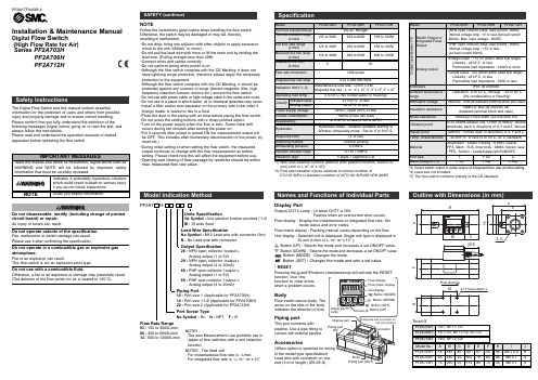
Installation & Maintenance Manual Digital Flow Switch(High Flow Rate for Air)Series PF2A703HPF2A706HPF2A712HDo not use with a combustible fluid.Otherwise, a fire or an explosion or damage may potentially result.(The detector of the flow switch for air is heated to 150°C).Do not operate in a combustible gas or explosive gasatmosphere.Fire or an explosion can result.This flow switch is not an explosion proof type.Units SpecificationNo Symbol :Unit selection function provided (*1,2)M :SI units fixedLead Wire SpecificationNo Symbol :M12 Lead wire with connector (3m)N :No Lead wire with connectorPF2A7 H-- -Flow Rate Range03 :150 to 3000L/min06 :300 to 6000L/min12 :600 to 12000L/minNOTE1 :The new Measurement Law prohibits use inJapan of flow switches with a unit selectionfunction.NOTE2 : The fixed unitFor instantaneous flow rate is : L/minFor integrated flow rate is : L, m3, m3x103Port Screw TypeNo Symbol :Rc N :NPT F :GBodyFlow switch sensor body. Thearrow on the side of the bodyindicates the direction of flow.Display PartOutput(OUT1)Lamp : Lit when OUT1 is ON.Flashes when an overcurrent error occurs.Flow display : Display the Instantaneous or integrated flow rate, Setmode status and error codes.Flow check display : Flashing interval varies depending on the flow.Unit display : Selected unit is displayed. Single unit type is displayed inSI unit (L/min or L, m3, m3x103).Button (UP) : Selects the mode and increases a set ON/OFF value.Button (DOWN) : Selects the mode and decreases a set ON/OFF value.Button (MODE) :Changes the mode.Button (SET) : Changes the mode and sets a set value.* RESETfunction. Use thisfunction to clear errorswhen a problem occurs.Accessoriesin the model type specification)end (3 m in length) (ZS-29-A)Names and Functions of Individual PartsOutput Specification28 :NPN open collector 1output +Analog output (1 to 5V)29 :NPN open collector 1output +Analog output (4 to 20mA)68 :PNP open collector 1output +Analog output (1 to 5V)69 :PNP open collector 1output +Analog output (4 to 20mA)Model Indication MethodPiping Port10 :Port size 1 (Applicable for PF2A703H)14 :Port size 1•1/2 (Applicable for PF2A706H)20 :Port size 2 (Applicable for PF2A712H)Piping portThis port connects withpipeline. Use a pipe fitting toconnect with external pipeline.(42.2)2-GFH5540DEOutline with Dimensions (in mm)*1) With units selection function (Without units selection function, fixed to SIunit [L/min or L, m3, m3x103])*2) Flow rate indication can be switched to normal condition of0°C/101.3kPa or standard condition of 20°C/101.3kPa/65%RH (ANR)*3) Select switch output or pulse output of integrated flow rate at initial setting.*4) Lead wire not included.*5) The flow switch conforms entirely to the CE standard.The Digital Flow Switch and this manual contain essentialinformation for the protection of users and others from possibleinjury and property damage and to ensure correct handling.Please confirm that you fully understand the definition of thefollowing messages (signs) before going on to read the text, andalways follow the instructions.Please read and understand the operation manuals of relatedapparatus before operating the flow switch.Do not disassemble, modify (including change of printedcircuit board) or repair.An injury or failure can result.Do not operate outside of the specification.Fire, malfunction or switch damage can result.Please use it after confirming the specification.NOTEFollow the instructions given below when handling the flow switch.Otherwise, the switch may be damaged or may fail, therebyresulting in malfunction.•Do not drop, bring into collision with other objects or apply excessiveshock to the unit (490m/s2or more).•Do not pull the lead wire with force or lift the main unit by holding thelead wire. (Pulling strength less than 49N)•Connect wires and cables correctly.•Do not perform wiring while power is on.•Although the flow switch complies with the CE Marking, it does nothave lightning surge protection, therefore please apply the necessaryprotection to the equipment.•Although the flow switch complies with the CE Marking, it should beprotected against any sources of surge (electro-magnetic lifter, highfrequency induction furnace, motors etc.) around the flow switch.•Do not use with power cable or high-voltage cable in the same wire route.•Do not use in a place in which water, oil or chemical splashes may occur.•Install a filter and/or mist separator on the primary side (inlet side) ifforeign matter is feared to mix in a fluid.•Flush the dust in the piping with air blow before piping the flow switch.•Do not press the setting buttons with a sharp pointed object.•Turn on the power supply when the flow is zero. Some initial driftoccurs during ten minutes after turning the power on.•For 3 seconds after power is turned ON the measurement output willbe OFF. This includes after momentary disconnection of the power, byreset etc.)•During initial setting or when setting the flow switch, the measuredoutput continues to change with the flow measurement as beforesetting. Please check how this will affect the equipment before use.•Opening and closing of flow passage by restrictor should be withinmax. measured flow rate value.4-I Thread depth JFlow directionConnector pin number15420Output SpecificationWhen the Lead wire with connector provided by SMC corporation is used the color of wire (Brown, White, Black, Blue) shown on circuit diagram will be applied.-28, -29NPN open collector 1 output + Analog outputMax.30V, 80mA Internal voltage drop : 1V or less-68, -69PNP open collector 1 output + Analog output Max.80mA Internal voltage drop : 1.5V or lessHow to attach connectors:•Turn off power before connecting or disconnecting the connector.•To insert the connector, push the connector socket of the lead wire to the key part of the switch connector after aligning them to each other and secure the connector with the lock nut.•To disconnect the connector, unlock the connector lock nut and pull out the connector straight.•Install the lead wire separately from the route for power cable or high-voltage cable. Otherwise, malfunction may potentially result due to noise.PF2A7 H- -28/68Output : 1 to 5VPF2A7 H - -29/69Output : 4 to 20mAH : Hysteresis n : Reverse P : Non-reverseSetting Procedure : Check installation condition and wiringInstantaneous switch output (oU1_0)See "Flow rate setting mode" to input setting value.OUT1 Output SpecificationsFlow rate per pulse Note1)Integration switch output (oU1_1)See "Flow rate setting mode" to input setting value.Integration Pulse output(oU1_2)Note1)Unit selection function type(Unit is fixed to SI unit for the type without this function)Note2)Reversed output is assigned at shipment.Function SettingNote1) Display unit setting is not available when the modelindication specifies the unit as "-M" (fixed units).Note 2) It does not go into Flow rate setting mode when theintegration pulse output [oU1_2] is selected as output specification.1. Initial setting modeBefore mounting the flow switch, read "Safety Instructions " and "Installation" described in this manual carefully to ensure safe and correct measurement.Mounting•Use this flow switch within the specified operating pressure range and operating temperature range.•Withstand pressure is 2.25 MPa.•Do not install a flow switch at a foothold position.•Install a flow switch so that the flow direction agrees with the arrow direction on the side of the body.•Mount the body so that the underneath of the body does not face upward.•Provide a straight pipe length of more than eight times the pipe diameter on the primary side (Inlet side) of the flow switch.•Set the required display part position taking the cable entry and display position into account. The display part rotates 270degree.Piping connections•Use a suitable pipe fitting to connect pipeline with the flow switch. Observe the specified tightening torque whenconnecting pipes. Refer to the following table for the appropriate •When connecting the pipeline to the flow switch, apply a spanner to the metal part of the flow switch body.•Make sure that sealing tapes do not enter inside the pipe when connecting pipes.Min. measured flow Max. measured flowInstantaneous flow [L/min]7.Flow rate setting modeInput the flow rate set value. Input method depends on OUT1 output specification. The flow switcht does not go into flow rate setting mode when the [oU1_2] integrated pulse output is selected for OUT1.Instantaneous switch output (oU1_0)1. Press button to select [n_1] ([P_1]) set value.[n_1] and the set value display alternately innon-reverse output mode).button.button to reduce.3. Press button to select [n_2] ([P_2]) set value.[n_2] and the set value display alternately in reverse output mode. ([P_2] and the set value display alternately in non-reverse output mode).and button as above.5. Press button to set the value.6.Window comparator mode: n_1<n_2(P_1<P_2)[HIS] and hysteresis set value display alternately.• Press button after selecting hysteresisbutton.• Hysteresis value is adjustable from 0 to 3% of rated flow value. If the difference between n_1(P_1) and n_2(P_2) is less than 6% of rated flow, the max. value of hysteresis is half of the difference between n_1(P_1) and n_2(P_2).7.Hysteresis mode : n_1 n_2(P_1 P_2) • Hysteresis value is not set.The hysteresis is determined by the difference between n_1 and n_2 (P_1 and P_2).Integration switch output (oU1_1)The value can be set up to 9999[m 3x 10³], 999[m 3which represents 9,999,999,999L1. Press button to input the set value in the digitand " L" are flashing.* Press button longer than 2 sec. to complete setting.button to reduce.3. Press button to input the set value in the digitof [m 3]. [n_3] ([P_3]) and the set value display alternately and "OUT" and "m 3" are flashing.* Press button longer than 2 sec. to complete setting.button as above.5. Press button to input the set value in the digit of [m 3x 10³].[n_3] ([P_3]) and the set value display alternately, and "OUT" and "m 3x 103" are flashing.* Press button longer than 2 sec. to complete setting.button as above.7. Press button to return to the status of 1. above.Press button longer than 2 sec. to complete setting.8.Flow conversion modeDisplays air flow converted during standard condition(nor : 0°C, 101.3kPa).1. Press button. [Anr]indicates standard condition, [nor]normal condition.2. Press button or button to complete the setting.Error Display and TroubleshootingThis function displays error location and nature. When a problem oran error occurs, take the following actions.Flow display checkCheck integrated flow when instantaneous flow is displayedbutton is pressed.button.)* The unit of integrated flow is changed as [L] [m 3] [m 3x 10³]button is pressed.Change the unit of integrated flow displayTo set the integrated flow display unit while integrated flow is displayed.button.2. The unit is changed as [L] [m 3] [m 3x 10³] [L] by pressingbutton.3. Unit stops flashing when the unit is selected by pressingbutton.* The unit stops flashing if no buttons are pressed for 5 seconds.The Integrated flow display unit is not changed.Clear the Integrated ValueThe Integrated value is cleared by pressing buttons simultaneously for 5 seconds.Initialize the Set ValueAll of the settings can be returned to initialized values at shipment.button simultaneously for longer than 2 seconds during initial setting mode [F_0]. Press button after [F_00]appears.* Setting is returned to [F_0] without change by pressing button.See below for settings at shipment.Display setting : Instantaneous flow(d_1)Unit setting : L/min(U_1)Output spec. : Instantaneous switch output(oU1_0)Output mode : Reverse output(oU1_n)Flow setting value : Instantaneous flow, Intermediate value of full-range/Integrated flow : 0Key lock mode : Unlocked(unL)Flow conversion condition : 20°C, 101.3kPa,65%RH[ANR](Anr)2. Display selecting modebutton to select desired flow, then press button.[d_1] instantaneous flow, [d_2] integrated flow.3. Display unit selecting modeDisplay unit can be selected when the units selection option is specified. -M means the unit is fixed to SI units, so it does not enter into Display unit selecting mode.6. Key lock modePrevents wrong operation such as unintentional change of set value.LOCK• Press button, and the display changes from • Setting is completed by pressing button.RELEASE• Press button longer than 3 sec. at the normal button.button.4. Output specification selecting modebutton to select OUT1 output mode, then pressbutton. [oU1_0] indicates instantaneous switch output, [oU1_1]indicates Integrated switch output, [oU1_2] indicates Integrated pulse output. Set the flow rate set value after selecting OUT1output mode. Flow rate setting is not required when selecting integrated pulse output [oU1_2].5. Output method selecting modeTo set OUT1 output mode. Reverse output and button to select the mode from reverse output or non-reverse output. Press button to set.[oU1_n] indicates reverse output mode, [oU1_P] indicates non-reverse output mode.Press button instead of button to move to [F_5].AUSTRIA (43) 2262 62280 NETHERLANDS (31) 20 531 8888 BELGIUM (32) 3 355 1464 NORWAY (47) 67 12 90 20 CZECH REP.(420) 541 424 611POLAND (48) 22 211 9600 DENMARK (45) 7025 2900 PORTUGAL (351) 21 471 1880FINLAND (358) 207 513513 SLOVAKIA (421) 2 444 56725 FRANCE (33) 1 6476 1000 SLOVENIA (386) 73 885 412GERMANY (49) 6103 4020 SPAIN (34) 945 184 100 GREECE (30) 210 271 7265 SWEDEN(46) 8 603 1200 HUNGARY (36) 23 511 390 SWITZERLAND (41) 52 396 3131 IRELAND (353) 1 403 9000 UNITED KINGDOM(44) 1908 563888ITALY(39) 02 92711URL (Global) (Europe)Specifications are subject to change without prior notice from the manufacturer. © SMC Corporation All Rights Reserved.Contact。
雷德科空气样品采集器与空气体积计说明书

RADēCO, INC“The Industry Standard in Air Sampling.”OPERATION AND MAINTENANCE MANUALAIR SAMPLER WITH AIR VOLUME TOTALIZERMODEL H-810BL17 West PkwyPlainfield CT 06374(860) 564-1220(860) 564-6631 Fax REV PreliminaryOPERATION AND MAINTENANCE MANUAL AIR SAMPLER WITH AIR VOLUME TOTALIZERMODEL H-810BL RADECO, reserves the right to change or revise this information without notice. Reasonable effort has been made to ensure that the information in this manual is accurate, however, RADECO, assumes no responsibility for inaccuracies or omissions of any kind.RADECO, makes no warranty for the use of its products.Copyright © 2013-15 RADECO, INC All Rights ReservedAny unauthorized reproduction, disclosure, copying or other use is strictly prohibited.CAUTIONCARE MUST BE TAKEN TO PREVENT THIS DEVICE FROM COMING INTO CONTACT WITH FOAM, LIQUID (INCLUDING WATER) AND OTHER FOREIGN SUBSTANCES. SUCH MATERIALS MUST BE PREVENTED FROM REACHING THE FAN SYSTEM INTAKE, MOTOR HOUSING AND ELECTRICAL COMPONENTS. FAILURE TO DO SO COULD RESULT IN AN ELECTRICAL SHOCK, WHICH MAY RESULT IN SEVERE BODILY INJURY OR EVEN DEATH IN EXTREME CASES.TABLE OF CONTENTSPage SPECIFICATION (1)DESCRIPTION (2)METHOD OF OPERATION (3)PRINCIPLE OF OPERATION (4)INSPECTI ON AND MAINTENANCE OF FLOW SENSOR (5)CALIBRATION (6)TROUBLESHOOTING (9)COMPATIBLE SAMPLE HOLDERS A ND OPTIONAL EQUIPMEN (10)APPENDICESFIGURE 1 – HEAD ADAPTOR ASSEMBLYLEGEND – FIGURE 1FIGURE 4 – PHOTO SENSOR CIRCUIT BOARD ASSEMBLYAPPENDIX A – KEYPAD AND DISPLAY CONFIGURATIONAPPENDIX B – TRIPODPage 1 SPECIFICATIONSOperational Range: Up to 99999 cubic feet, of 99999 litersAccuracy of Totalizer: +5%Readout of Totalizer: LCD: 2 Lines, 16 Characters, backlit. Continuousdisplay of cumulative volume + flow rate + elapsedtime. Flash memory backed to recall sample data inthe event of power loss.Timer Circuit: Microprocessor-controlled crystal oscillator Operating Voltage: 115-220VAC, 50-60Hz, 1 PhaseCurrent Rating: 800-1200 WattsDimensions: 11” Wide, 8 1/2” Deep, 9” HighWeight: 17.5 pounds (8 Kg)Air Mover: Internally mounted; Brushless IntelliGen Blower Motor: 1 HP, self-cooled, brushlessEye Bolt: Top mounted, for carrying or hanging sampler.Supplied with 2” wide, 6 foot long belt.Air Flow Adjust Control Recessed, to be set by calibration person. ON/OFFswitch/circuit breaker controls AC power to unit. Operating Conditions For use in a dry environmentKeypad, 16 Key – Features: Start Key: Initiate pre-programmed sample.Stop Key: Manually terminates sample.Units Key:Toggles display between litersand cubic feet units.Set Key:Allows user to change samplepreset.Numeric Keys:Allows entry of numeric valuesin response to displayed menus.Page 2Calibration:After sample has been clearedpress Clear, enter the calibrationcode, 3434, then press EnterSecurity:Keypad function can beselectively limited to Start/Stopand Units, in order to preventchanging of sample presets.DESCRIPTIONThe RADēCO Model H-810BL is a dependable, lightweight air sampler which incorporates the reliability, ruggedness, and technology of the Model H-810DM with an IntelliGen brushless blower for continuous high volume sampling as well as standard grab samples.The H-810BL uses an Air Volume Totalizer composed of an enclosed air-turbine, which rotates at speeds proportional to the air velocity of the sampled air. The turbine’s rotation is sensed by a reflective sensor/breaker disc. The microprocessor converts the signal to volume and displays the flow rate, total volume and elapsed time on the LCD readout. The Model H-810BL may be operated in either the “Total Volume” mode or the “Total Elapsed Time” mode with the mode of operation selected during instrument calibration. The functions/parameters that are established during calibration may be locked-in using the “keypad security” feature. When keypad security is en abled, the SET function on the keypad is disabled, which prevents the operator from altering the sample presets.The operation of the Model H-810BL is a very simple four-step procedure and the training time required is relatively short. Its operational procedure is:1.Connect to an AC power source.2.Install the sample holder with the filter media.3.Turn power switch on.4.Press the START key.The Model H-810BL samples the environment until the desired total volume or total elapsed time has been reached and then turns itself off. The LCD readout indicates the total volume and elapsed sample time. A STOP key is provided to stop the sampling procedure at any point during the sampling period, and the total volume of air sampled, and elapsed time up to that point are indicated.Page 3The Model H-810BL is supplied with a 2 inch wide, 6 foot long belt for carrying purposes or for hanging the instrument during sampling. The instrument is not designed to be suspended by the power cord.METHOD OF OPERATIONOperation of the H-810BL is simplified through the use of English-language prompts on a digital display. After turning the unit ON, the display will prompt for the calibrated range desired. After selecting either 1, 2, or 3 the selected calibration range will be displayed (note: 1, 2, or 3 will only appear if a multi-calibration unit was purchased). Pressing CLEAR at this point will return to the select calibration 1, 2, or 3 display. Pressing any other key on the keypad will cause the unit to indicate the current preset volume or time. At this point a sample may be initiated by pressing the START key, or the preset may be changed by pressing the SET key. i.e.:CALIBRATED RANGE to1, 2 or 3?Calibrated Range to Target Volume:or Target Run Time:4.0 to 6.0 CFM 1000 ft3 10:00 After pressing the SET key, the display will prompt for a new target time or volume, depending on the current mode of operation selected during the last calibration. i.e.: Enter Target or Enter Target or Enter TargetTime: 00:00 Volume 0 ft3 Volume 0 lit Enter a new value using the digit keys followed by ENTER, or press ENTER to cancel changing the target.The H-810BL is equipped with KEYPAD SECURITY. With this feature enabled, the SET function on the keypad is disabled, preventing the operator from altering the preset sample time or volume. This feature also inhibits the display of the current calibrated range upon power-up.Upon pressing the START key, the motor will turn on, and the display will indicate the “warm-up delay”, if enabled. The display will then indicate the current totalized volume, the current flow rate, and the elapsed time (volume mode) or remaining time (time mode). i.e.:ft3 CFM Time or lit LPM Time123.4 4.5 12:34 12345 123 12:34If the FLOW RATE reading is blinking during sample collection, it is because the unit is running at a flow rate outside of its calibrated range. This can be corrected by recalibrating the unit.The unit will continue to sample unit the target time or volume has been reached, or until the STOP key is pressed. Upon completion or termination of a sample, the display will indicate the final time/volume of the sample. i.e.:Volume: 123.4 ft3Run Time: 12:34NOTE: In the event that power is disconnected or turned off prior to completion of a sample, the elapsed time/volume will be displayed upon power-up. The CLEAR key must be pressed to clear the last run and again display the originally set target volume. When using the Model H-810BL with the optional tripod for breathing zone sampling applications (See Appendix C), please note the adaptor or tripod mounting block may be installed on the bottom or the front of the unit. When the adaptor is mounted on the front, the keypad display is most accessible.PRINCIPLE OF OPERATIONThe principle of operation of the air volume totalizer is very simple and basic in nature. Theoretically, a fan mounted on a freely turning shaft will rotate at a rate proportional to the velocity of the air passing the fan. This velocity is proportional to the flow rate, assuming the pressure differential across the filter media stays constant, and the ambient air temperature/pressure stays constant. By measuring the fan RPM for a number of flow rates, a nearly linear response can be generated between the airflow rate and the fan speed.RADēCO tested the above principle and learned that the above was true within limits. We found that for each filter media, the turbine speed was close to linear, but only over a limited flow range. The CFM versus RPM curve also varied depending on the pressure drop of different filter media. For any given filter media, we found that by using a threePoint calibration we could very closely track the CPF/RPM curve with linear approximations over a relatively wide flow range. The microprocessor determines all calibration constants required based on operator-entered flow rates and measured turbine RPM during the calibration process. These constants are permanently stored in Flash memory or until overwritten. Recalibration is only required if or when a different type of filter media is to be used.The Model H-810 has been designed using the latest in technology. The unit is microprocessor-based with Flash memory to permanently store operational parameters until overwritten. The microprocessor keeps track of turbine RPM by counting pulses from a reflective sensor/breaker disk located in the head adapter.INSPECTION AND MAINTENANCE OF FLOW SENSOR1.Carefully remove front barrel (See Figure 2, Item 2) by turningcounterclockwise.2.Inspect six holes in barrel focusing plate and clean holes with isopropylalcohol if there is any dirt present.3.Inspect fan for wear around edges and the presence of dirt. This is acompression fitted fan, which may be readily removed from the shaft forcleaning or replacement.4.Check space setting between front of bearing support and rear of fan. Thisshould be 0.5 inches.5.Verify that fan turns freely without binding and is free of wobble, which mayindicate a bent fan shaft.6.Replace barrel and cinch down tight. Again verify that the fan turns freely byblowing into the barrel. The fan should come to a stop gradually and withoutresistance.7.To clean photo sensor, remove right case half (four screws). Remove photosensor circuit board assembly (two screws). Clean photo sensor using a softcloth or cotton swab and reassemble.CALIBRATION1.Install a sample holder assembly containing the filter or combination filter andcartridge normally to be used for air sampling into the front of the barrel and connect inlet to air flow calibrator (RADēCO Model C-828 or C-8528, depending on filter media, with adaptor). See Figure 5.2.Plug unit into AC power supply.3.Press CLEAR and enter the calibration code “3434” then press ENTER4.If Step 3 has been done correctly, after approximately five seconds the displaywill prompt:CALIBRATE FLOW?1= YES, 0= NOPress “1” for Yes.5.Display will read:VOLUME UNITS?1= ft3, 0=liters, 2= m36.Display will read:Adjust Flow For then Enter high FlowHigh Flow Rate Rate: 0.0 CFMAdjust flow to high point of calibration range by using a small flat head screw driver and adjusting the potentiometer located on the side of the unit (Example: 3-4-5 CFM, 3 = LOW POINT, 4 = MID POINT, 5 = HIGH POINT) Enter the high flow rate using the keypad and then press “ENTER”. Keep flow constant for 10 seconds.7.Display will read:Adjust Flow For then Enter Mid FlowMid Flow Rate Rate: 0.0 CFMReduce flow to mid point of calibration range. Enter rate using keypad and then press “ENTER”. Keep flow constant for 10 seconds.Page 7 8.Display will read:Adjust Flow For then Enter Low FlowLow Flow Rate Rate: 0.0 CFM Reduce flow to low point of calibration range. Enter rate using keypad and then pr ess “ENTER”. Keep flow constant for 10 seconds.9.Display will read:Verify LinearityRate: 0.0 CFMAdjust flow to various points within the calibration range to verify calibration accuracy. Press ENTER to accept calibration or CLEAR to reject. At this point the motor will shut off.NOTE: If display reads “BAD CALIBRATION”, or “TURBINE FAILURE”then inaccurate flow data has been entered, or the turbine speed sensor requires service.10.Display will read:Default Run Mode0=Vol, 1=Time:Select mode o f operation. Select “0” for TOTAL VOLUME, select “1” for TOTAL TIME.NOTE: During normal operation, both volume and time are displayed.11.Display will read:Enter Target or Enter TargetTime: 00:00 Volume 0 ft3 or 0 liters or 0 m3 Enter default sample time or volume using the keypad.Page 8NOTE: This is the default target that will be displayed each time the unit is turned on. If keypad security is disabled, this number may be temporarily changed using the SET function, described above.12.Display will read:Altitude & Temp1=Actual, 0=StandardSelect either “0” for no automatic altitude and temperature correction or “1” if you would like the unit to use correction factors for the temperature andatmospheric pressure of where you will be taking samples. Enter desired altitude in feet, press ENTER, and then enter temperature in degrees F, press ENTERNOTE: This information must be entered Imperial Units, to get to Imperial Units select “0” then finish calibration st eps 13 and 14. Then press the UNIT key totoggle to “CFM”. Now you can re-enter press CLEAR, enter the calibration code, and cycle through the prompts until you are back too “Altitude & Temp”. Units may be changed back by pressing the UNITS key before a sample is taken.13.Display will read:Warm-Up Delay InSeconds (0-9):Enter the time desired for the unit to come up to speed, before actual sampling totalizing period begins (typically two seconds).14.Display will read:Keypad Security?0= OFF, 1= ON:Select either “0” for OFF or “1” for ON. When keypad security is on, all keys on the keypad are disabled with the exception of the UNITS, START and STOP keys. These keys will allow the user to start the run or toggle the display readout from CFM, LPM, or M3units using the UNITS key.NOTE: To change these default run parameters without recalibrating flow, follow steps 3 and 4. On step 4: CALIBRATE FLOW, enter “0” for NO. For RPM TEST MODE, enter “0” for NO. Display will prompt for “VOLUME UNITS”.Select desired units of measure per the menu prompts, and continue through steps12 through 16.Page 9 TROUBLESHOOTING:The H-810BL has capabilities for checking the performance of the turbine sensor and the battery monitor.TURBINE TEST MODEThe H-810BL has a built in diagnostic tool to test your H-810BL turbine.1. Make sure you have your flow rate set to maximum with no filter mediainstalled.2. Press “1” and the pump will turn on, and the diagnostic will start3. Results will display on the screen•High RPS•Low RPS•Span of RPS•Average RPS•Spin down timeSigns of a bad turbine include a difference between the high and low of more than20 RPS or a spin down time of less than 5 seconds.To exercise the turbine, select NO at the CALIBRATE FLOW? prompt, then YES at the RPM TEST MODE? prompt. The display will indicate the RPM rate as sensed by the reflective sensor circuit. This rate is nearly proportional to flow, and the range is affected by the filter media and the turbine barrel hole configuration.Page 10 COMPATIBLE RADēCO SAMPLE HOLDERS AND OPTIONAL EQUIPMENT FOR H-810BLModel No. Open Face2500-232” Diameter Filter2500-3347mm Diameter FilterOpen Face Combination2500-192” Diameter Filter / RADēCO Cartridge2500-272” Diameter Filter / Scott Cartridge2500-3447mm Diameter Filter / RADēCO Cartridge2500-3947mm Diameter Filter / Scott CartridgeFOR H-810BL-2Model No. Open Face2500-25A 4” Diameter FilterAvailable Filter PapersModel No. Diameter Type0750-02 47mm HD-20640750-03 2”HD-20640750-09P 4”HD-20640750-36 47mm LB-52110750-37 2”LB-52110750-49 4”LB-5211TripodModel TRP-2 (with Adaptor) See Appendix CFIGURE 1LEGEND-FIGURE 1HEAD ADAPTOR ASSEMBLYITEM PART NO. DESCRIPTION1 106010-1, -2, -3 Head Adaptor2 7000-03 Cartridge Bearing3 S2-16 Ultra Precision Shaft4 6050-49 Fan Blade5 106013-1 Sensor Disc6 106004-1 Photo Sensor PCB Assembly7 1350-22 Screw, 4-40 x .25 Pan Head8 1550-88 Washer, Fiber, #49 2201-11 O-Ring12 2201-09 O-RingFIGURE 4PHOTO SENSOR CIRCUIT BOARD ASSEMBLYFIGURE 5 APPENDIX AKEYPAD AND DISPLAY CONFIGURATIONAPPENDIX B TRIPODTRIPOD – P/N TRP-238” to 61” Weight 10 ½ LBSMachined aluminumhead mates to TRP-adapterDurable light weight aluminum legs lock in any positionAdjusts between 39 inches and 61 inchesSteal spur allows for a firm setupTripod adapter。
安迪莱 IRmax 双光线红外化学气体探测器说明书

IRmaxSpecificationSizeIRmax158 x 75 x 57mm (6.2 x 2.9 x 2.3ins)IRmax with Fixed IR display 230 x 75 x 57mm (9 x 2.9 x 2.3ins)IRmax with IS Barrier Module 261 x 75 x 57mm (2.3 x 2.9 x 2.3ins)Remote IR Display60 x 54 x 48mm (2.3 x 2.1 x 1.9ins)WeightIRmax1.58kg (3.5lbs)IRmax with Fixed IR Display 2kg (4.4lbs)IRmax with IS Barrier Module2.4kg (5.3lbs)Remote IR Display0.2kg (0.4lbs)Enclosure material 316 stainless steelDescription Dual-beam infrared hydrocarbon gas detector with optional display Ingress protection IP66Connection One M20 or ½” NPT cable gland entry Power12-30 Vdc. < 1WElectrical output4-20mA current sink or source2mA dirty optics warning (at 75% obscuration, configurable)0mA detector fault signal (at 90% obscuration, configurable)RS-485 Modbus (optional), HART 7 (optional)IR display4- digit LCD with back-lightFunction buttons can be de-activated if requiredT erminals for connecting HART communicators (optional function)LEDRed: Gas detectedAmber: IRmax faultGreen: HealthyDisplay functionsGas level, obscuration level, supply voltage, signal current Password protected functionsZero, calibrate, ramp output, trim zero mA, trim span mA Operating temperature -40o C to +75o C (-40o F to 167o F)Humidity 0 to 95% RH non-condensing Pressure range Atmospheric +/- 10%Repeatability +/- 2% FSDZero drift +/- 2% FSD per year maximum Rresponse time T90 < 4 seconds Functional safetyIEC61508, EN50402 SIL2Approvals ATEX & IECExIRmax without DisplayEx II 2 GD Ex db IIC T6 Gb (T amb -40°C ≤ T a ≤ +50°C) Ex II 2 GD Ex db IIC T4 Gb (T amb -40°C ≤ T a ≤ +75°C) Ex II 2 GD Ex tb IIIC T135°C Db (T amb -40°C ≤ T a ≤ +75°C) IRmax with Remote and Handheld Display Ex II 2 GD Ex db ia IIC T4 Gb (T amb -40°C ≤ T a ≤ +75°C) Ex II 2 GD Ex tb ia IIIC T135°C Db (T amb -40°C ≤ T a +40°C) IRmax with Fixed DisplayEX II 2G Ex db ia IIC T4 Gb (T amb -40°C ≤ T a ≤ +75°C)EMC Compliance EN50270, FCC CFR47 Part 15B, ICES-003Accuracy +/- 2% of reading Linearity+/- 3% of full-scaleCompact sizeRequires less space, effort and time to installVarious installation options Can be wall mounted, fitted to a 50mm (2 inch) pipe or connected to an auxiliary junction box using a choice of mounting acessories Industry standard 4-20mA outputIRmax is compatible with virtually any control systemOptions for HART communications and RS-485 ModbusRemote non-intrusive calibrationThe Remote Display can be mounted up to 30 metres from the IRmax and test gas can be applied without requiring direct access to the detector Hand-held Intrinsically Safe (I.S) calibrator IRmax detectors fitted with an I.S barrier module can be checked and calibrated using an I.S handheld display STAY -CLIR opticsPrevents condensation on optical componentsLow powerIRmax only consumes 1W of power, enabling small power supplies and battery back up systems to be used Automatic optical obscuration monitoring Minimal routine maintenance keeps costs to a minimumAnnual proof-test intervalIRmaxInfrared Hydrocarbon Gas DetectorLinearisation RangeAcetone (C 3H 6O)Pentane (C 5H 12)Paraxylene (C 8H 10)0-100% LEL Butane (C 4H 10)Petrol vapour Ethane (C 2H 6)Ethanol (C 2H 5OH)Propane (C 3H 8)Ethylene dichloride (EDC)Ethylene (C 2H 4)Propylene (C 3H 6)Cyclohexane (C 6H 12)Ethyl acetate (C 4H 8O2)THF (T etrahydrofuran) (C 4H 8O)Butadiene (C 4H 6)Heptane (C 7H 16)Xylene (C 8H 10)T oluene (C 7H 8)Hexane (C 6H 14)Methyl acetate (C 3H 6O 2)Butene (C 4H 8)LPGPropylacetate (C 5H 10O 2)Methyl Ethyl Ketone (MEK)Methanol (CH 3OH)Hexene (C 6H 12)Isopropanol (IPA)Methane (CH 4)0-50, 100% LEL Other ranges & calibrations may be available, please contact Crowcon if your requirement is not shown.IRmax is a compact, low power and highly rugged infrared gas detector, that delivers rapid, fail safe detection of methane, butane, propane and many other hydrocarbon gases and vapours.DisclaimerEvery effort has been made to ensure the accuracy of this document at the time of printing. In accordance with the company’s policy of continued product improvement Crowcon Detection Instruments Limited reserves the right to make product changes without notice. The products are routinely subject to a programme of testing which may result in some changes in the characteristics quoted. Technical information contained in this document or otherwise provided by Crowcon are based upon records, tests, or experience that the company believes to be reliable, but the accuracy, completeness, and representative nature of such information is not guaranteed.Many factors beyond Crowcon Detection Instruments’ control and uniquely within user’s knowledge and control can affect the use and performance of a Crowcon product in a particular application.As the products may be used by the client in circumstances beyond the knowledge and control of Crowcon Detection Instruments Limited, we cannot determine the relevance of these to an individual customer’s application. It is the clients’ sole responsibility to carry out the necessary tests to evaluate the usefulness of the products and review all applicable regulations and standards to ensure their safety of operation in a particular application.。
- 1、下载文档前请自行甄别文档内容的完整性,平台不提供额外的编辑、内容补充、找答案等附加服务。
- 2、"仅部分预览"的文档,不可在线预览部分如存在完整性等问题,可反馈申请退款(可完整预览的文档不适用该条件!)。
- 3、如文档侵犯您的权益,请联系客服反馈,我们会尽快为您处理(人工客服工作时间:9:00-18:30)。
3.1概述...........................................................................................................................................................21
不承担责任的声明
如果使用者、个人、公司、实体、企业或者团体在对产品进行全部及部分使用、安装或者储存时未遵照本手册中的指南和警告或者未遵照经销商所提供的其它指南和警告,以及未遵照所有联邦、州和当地的环境及职业健康和安全法律和法规,那么对于由此带来或者由此造成的任何当事人的财产损失、人身伤害或者死亡,经销商不承担任何责任。
2.1.1采样杆...................................................................................................................................................16
1.3控制和指示器...........................................................................................................................................12
第二部分:架设
2.1一般的架设...............................................................................................................................................16
2.2.1使用DC部件.........................................................................................................................................17
1.4.1可伸缩的采样杆...................................................................................................................................12
1.4.2空气软管和软管支撑头.......................................................................................................................12
2.1.2空气软管...............................................................................................................................................16
2.2.2用电源组件充电...................................................................................................................................17
4Sensidyne文件编号No.F-PRO-3100(Rev E)
1.2.3电源组件...............................................................................................................................................10
版权公告
©1998-2002,Sensidyne公司。版权所有。本文文件中所包含的信息受版权保护。在事先未得到Sensidyne公司的书面授权时,本文档中的任何一部分都不得进行影印、复制或者翻译为其它程序或体系。
商标公告
Sensidyne、Sensidyne标识、Gilian以及Gilian标识是Sensidyne公司的注册商标。这些商标在使用中受到保护,并且已经在美利坚合众国进行了注册。本文文件中所用到的商标和服务标记是其相应公司的财产,其目的仅仅是用于信息和说明。
3.2基本操作...................................................................................................................................................21
1.2.2DC(直流)电源........................................................................................................................................10
1.3.3LCD显示...............................................................................................................................................12
Gilian®
AIRCON-2
高流量空气采样器
操作及维修手册
16333 Bay Vista Dr.•Clearwater,FL33760•(800) 451-9444•(727) 530-3602•(727) 539-0550 [FAX] *
修订版E·档编号No. F-PRO-3100
2.1.3滤匣.......................................................................................................................................................16
●包装清单................................................................................................................................4标准零件...................................................................................................................................................12
1.3.2流量调节...............................................................................................................................................12
1.2.1AC(交流)电源........................................................................................................................................10
1.1描述.............................................................................................................................................................9
3.2.1单模式...............................................................................................................................................21
2.2充电...........................................................................................................................................................17
Gilian®AIRCON-2高流量空气采样器
所有权公告
本手册是Sensidyne公司专门为AirCon-2高流量空气采样器的用户所准备的。本手册中的数据为Sensidyne公司独家所有的信息,仅用于了解、操作和维修本仪器。在得到本文档时,读者应同意本文档和文文件中所透露的信息以及其中的任何一部分不得以书面、电子或者任何其它方式进行复制及传递,也不得用于或者透露给其它人用于生产或者任何其它目的,除非由Sensidyne公司以书面方式进行专门的授权。
1.2电源...........................................................................................................................................................10
1.3.1开/关按钮..............................................................................................................................................12