毕业论文--基于飞思卡尔单片机的智能车设计(含外文翻译)
单片机智能小车毕业论文中英文资料外文翻译外文文献

单片机智能小车外文翻译通过研发实现了一种以光电传感器为敏感元件,以AT89C51 单片机为控制核心的电动循迹小车的智能控,该系统还包括直流电机、L9110 芯片和LM324 比较器等。
本设计采用AT89C51 单片机作为智能小车核心控制器。
本系统以单片机为控制核心,实现电动车的前进、退、左转和右转功能.通过角度传感器[ 1 ]检测跷跷板角度的变化,利用增量式PI算法[ 2 ]控制电动车寻找平衡点,同时运用光电传感器检测黑线,使电动车在行驶过程中保持直线运动且不会脱离跷跷。
一.方案设计电动车的速度、位置、运行状况的实时测量,并将测量数据传送至单片机进行处理,然后由单片机根据所检测的各种数据实现对电动车的智能控制。
这种方案能实现对电动车的运动状态进行实时控制,控制,灵活可靠,精度高,可满足对系统的各项要求。
直流调速系统采用脉宽调速系统,其主电路采用脉宽调制式变换器,简称PWM变换器。
由于PWM调速系统的开关频率较高,仅靠电枢电感的滤波作用就可以获得脉动很小的直流电流,电枢电流容易连续,系统的低速运行平稳,调速范围较宽,可达1:10000左右。
由于电流波形比V-M系统好,在相同的平均电流下,电动机的损耗和发热都比较小。
同样由于开关频率高,若与快速响应的电机相配合,系统可以获得很宽的频带,因此快速响应性能好,动态抗扰能力强。
根据以上综合比较,以与本设计中受控电机的容量和直流电机调速的发展方向,本设计采用了H型单极型可逆PWM变换器进行调速。
1.1光电检测模块设计该智能小车在贴有黑线的白纸“路面〞上行驶,因此本模块设计需要检测铺在行驶区的黑胶带,包括直线行驶区和沿弧线行驶区两个区域。
由于黑线和白纸对光线的反射系数不同可根据接收到的反射光的强弱来判断“道路〞---黑线。
本文采用的是简单实用的检测方法,即红外探测法。
红外探测法,即利用红外线在不同颜色的物理表面具有不同的反射性质的特点。
在小车行驶过程中不断地向地面发射红外光,当红外光遇到白色地面时发生漫发射,反射光被装在小车上的接收管接收;如果遇到黑线则红外光被吸收,则小车上的接收管接收不到信号。
基于飞思卡尔的自主寻迹智能车的设计
其中.FOR循环包含了检测黑线位置.更新舵机输出等。具 体见图3.
本小车对黑白线的检测使用了12个红外管,实行等距排 列。这12个er夕l,管将坐标细分为23个坐标值对赛道黑线位置 进行判断。对于采集的数据.使用循环检测的方法,即从左边的 光电管开始,检测其是否在黑线上:如果在,那么接着检测其右 边的光电管是否亦如此,依次向右推进:当出现3个以上光电 管同时处于黑线上方.则过滤掉当前采样数据.采用历史值。
2.期刊论文 高凤水.靳涛.赵书朵 基于飞思卡尔单片机的智能车设计 -电子设计应用2008(5)
本文设计一种能在跷跷板上根据预定轨迹行驶,并且可以使跷跷板保持平衡的电动车.它以飞思卡尔MC9S12DG128单片机作为控制核心,由驱动调速模 块、路面检测模块、显示模块、电源模块等几部分组成.本设计的平衡杆力矩补偿装置可以使跷跷板的调节平衡精度更高.
对小车方向控制的设计.采用的是模糊控制的思想,并结
FOR循环
④
图2主流程图
厂—1磊1 磊i]
I....................................————.——.................................J
I
检测’前速度
更新电机输出
-
判断是否到终点停车
围3 FOR循环 合了PID控制方法。首先。确定模糊控制器的输人变量和输出 变量,输入量即为黑线坐标,而输出量便是舵机所对应的角度: 第二,编制模糊表,加快对弯道的处理速度;第三,由于小车每 次进人同一个弯道时速度、角度都会不同.所以还需要加入 PID算法进行修正,尤其是D的引入,将本次和上次遇到同个 弯道时传感器采集到的数据进行处理。不断将入弯偏差减小或 者消除.达到平滑入弯的目的。
基于飞思卡尔单片机自动循迹小车控制的设计
摘要随着我国的电子科技的不断发展,我们生活中的自动化设备越来越多,也为嵌入式在智能化上的研究提供了一个广阔的平台。
本系统以MK60DN512VMD100微控制器为核心控制单元,选用OV7620 CMOS 模拟摄像头检测赛道信息,高速AD转换芯片选用TCL5510,将提取后的灰度图像进行软件二值化,进而提取赛道信息;用光电编码器实时检测小车的实时速度,采用PID控制算法调节电机的速度以及舵机转向,从而实现速度和方向的闭环控制。
关键字:MK60DN512VMD100,OV7620 CMOS,软件二值化,PIDAbstractWith the continuous development of electronic technology, more and more automation equipment into the production life of the people, the rapid development of embedded intelligent study provides a broader platform.In this paper, the design of intelligent vehicle system MK60DN512VMD100 microcontroller as the core control unit, the selection of OV7620 CMOSanalog cameras to detect the track information, to using TCL5510 high-speed AD converter chip, software binarization image, extract the white guide line for identification of the track information; optical encoder to detect the real-time speed of the model car, using the PID control algorithm to adjust the speed of the drive motor and steering the angle of the steering gear, in order to achieve closed-loop control of velocity and direction of the model car. Keywords: MK60DN512VMD100,OV7620 CMOS,software binarization, PID目录摘要 (I)Abstract .................................................................................................................................. I I 1前言 (1)1.1 设计的背景以及意义 (1)1.2 智能小车国内外概况 (1)1.2.1国内研究的概况 (1)1.2.2 国外研究概况 (2)1.3智能小车的发展前景 (2)2 飞思卡尔单片机自动循迹小车系统设计总方案 (3)2.1 系统硬件部分 (3)2.2 系统软件部分 (4)3 智能车硬件系统 (5)3.1 单片机最小系统 (5)3.1.1 PIT定时器模块 (6)3.1.2 PWM 模块 (6)3.1.3 I/O模块 (7)3.1.4 时钟电路 (7)3.1.5 复位电路 (7)3.1.6 JTAG接口电路 (8)3.2 电机驱动模块 (8)3.3路径识别摄像头检测模块 (9)3.3.1 摄像头的选择 (9)3.3.2 摄像头简介 (10)3.4 速度检测模块 (10)3.5 舵机模块 (10)3.6电源管理模块 (10)3.6.1 3.3V电源 (11)3.6.2 5V电源 (11)4 软件系统的设计与实现 (12)4.1赛道信息的提取 (12)4.2 PID算法介绍 (12)4.2.1 位置式PID (13)4.2.2 增量式PID (14)4.2.3 PID 参数整定 (14)4.3转向舵机的控制方法 (15)4.3.1 舵机的工作原理 (15)4.3.2 舵机的PID 控制 (15)5 开发平台介绍 (19)5.1 IAR Embedded Workbench IDE简介 (19)5.2 IAR Embedded Workbench的功能及特点 (19)5.3 硬件开发平台Altium Designer (22)6结论 (23)参考文献 (24)致谢 .................................................................................................... 错误!未定义书签。
智能小车优秀毕业论文
智能小车优秀毕业论文编号本科生毕业设计基于单片机的智能小车设计The Design of Intelligent Vehicle Based on MCU 学生姓名xxx专业自动化学号xxx指导教师xxx学院电子信息工程二〇一三年六月毕业设计原创承诺书1.本人承诺:所呈交的毕业设计(论文)《基于单片机的智能小车设计》,是认真学习理解学校的《长春理工大学本科毕业设计(论文)工作条例》后,在教师的指导下,保质保量独立地完成了任务书中规定的内容,不弄虚作假,不抄袭别人的工作内容。
2.本人在毕业设计(论文)中引用他人的观点和研究成果,均在文中加以注释或以参考文献形式列出,对本文的研究工作做出重要贡献的个人和集体均已在文中注明。
3.在毕业设计(论文)中对侵犯任何方面知识产权的行为,由本人承担相应的法律责任。
4.本人完全了解学校关于保存、使用毕业设计(论文)的规定,即:按照学校要求提交论文和相关材料的印刷本和电子版本;同意学校保留毕业设计(论文)的复印件和电子版本,允许被查阅和借阅;学校可以采用影印、缩印或其他复制手段保存毕业设计(论文),可以公布其中的全部或部分内容。
以上承诺的法律结果将完全由本人承担!作者签名:• 年•• 月• 日摘要随着我国高科技水平的不断提高和工业自动化进程的不断推进,智能车被广泛应用于各种玩具和其他产品的设计中,极大地丰富了人们的生活。
本文基于ATmega16 单片机设计了一种智能循迹避障小车,由电源模块、红外传感器模块、电机驱动模块、调试模块和MCU模块组成。
利用红外对管和超声波检测黑线与障碍物,当左边的红外对管检测到黑线时,小车往左边偏转,右边的红外对管检测到黑线时,小车往右边偏转。
以ATmega16单片机为控制芯片控制电动小车的速度及转向,从而实现自动循迹避障的功能。
其中小车驱动由L298N驱动电路完成,速度由单片机控制。
关键词:智能小车单片机自动循迹避障AbstractWith the increasing levels of high-tech and industrial automation process progresses, the intelligent vehicle is widely used to all kinds of toys and another production’s devise. It is greatly enriched the life of the people.Based on ATmega16 microcontroller,this paper is about a design of intelligent tracking-avoidance car, which is consist of the power supply module, infrared sensor module, the motor drive module, debug module and the MCU modules. Using infrared and ultrasonic testing on the tube black line and the obstacle, when left on the tube detects infrared black line, the car deflected to the left, the right of infrared tube black line is detected, the car to the right deflection. ATmega16 microcontroller for the control chip to control the speed and steering electric car, enabling automatic tracking avoidance function. Which car is driven by L298N driver circuit completed, the speed controlled by the MCU.Keywords: Intelligent Vehicle; MCU;automatic tracking; obstacle avoidance目录摘要 (I)ABSTRACT (II)目录 (III)第1章绪论 (1)1.1引言 (1)1.2课题研究目的及意义 (1)1.3课题研究现状及发展趋势 (2)1.4本文的主要工作 (3)第2章小车的总体方案设计 (4)2.1设计思路 (4)2.2小车循迹避障传感器的选型 (6)2.3小车循迹避障设计方案 (8)第3章小车的硬件电路设计 (10)3.1单片机的选型 (10)3.2小车的硬件电路设计 (14)第4章小车的软件设计 (19)4.1主程序设计及流程图 (19)4.2避障子程序设计及流程图 (20)4.3循迹子程序设计及流程图 (21)结论 (22)参考文献 (23)致谢 (24)附录1 系统电路图 (24)附录2 智能循迹壁障小车完整程序 (27)第1章绪论1.1引言智能,在科技高速发展的今天,已成为一个引领时尚前沿的代名词,智能手机,智能机器人等等已经在工业,军事中得到广泛的作用,在不为人们所熟知的领域,如深海探测,航空航天,地质勘探,智能也发挥着举足轻重的作用[1]。
基于飞思卡尔单片机的智能小车设计与应用
基于飞思卡尔单片机的智能小车设计与应用毕业设计 (论文)专业通信工程班级10级1班学生姓名刘新学号10205040117课题基于飞思卡尔单片机的智能小车设计与应用---主监控程序和行使操纵程序的设计指导教师夏巍2021年6月1日摘要本文要紧是以全国大学生〝飞思卡尔〞杯智能小车竞赛为背景的一项课题研究。
本次课题研究要紧采纳利用飞思卡尔公司的32位单片机MPC5604MINI作为核心操纵单元,用CCD进行对道路信息的采集,用编码器对小车速度进行检测,使用7.2V锂电池进行供电,并用MPC5604MINI产生PWM波操纵电机模块和舵机模块,从而达到操纵小车的速度和转向。
本文要紧介绍主监控程序和行驶操纵程序的编写,确实是编写程序让小车各个部分和谐工作,让小车行驶并能够实现转向。
关键词:智能小车;MPC5604MINI;主控电路;行驶操纵。
AbstractThis article is based on National College "Freescale Cup" smart car competition as a research background.The research mainly uses Freescale's 32-bit singlechip as the core control unit MPC5604MINI,and Carried out on the road with a CCD information collection, and use encoder to detect the speed of the car, using a 7.2V lithium battery-powered and used to generate PWM wave MPC5604MINI module and servo motor control module, so as to control the car's speed and steering.This paper describes the preparation of the master control procedures and driving control program, is to write the program so that the coordination of the various parts of the car, so the car driving and steering can be achieved.Keywords: Smart car;MPC5604MINI;Control circuit;Driving control.目录摘要 (Ⅰ)Abstract (Ⅱ)1引言 01.1课题研究意义 01.2 智能小车国内外概况 01.2.1 国内研究概况 01.2.2 国外研究概况 (2)1.3 智能小车进展前景 (2)2 系统设计及方案论证 (3)2.1 系统设计要求 (3)2.2 系统设计方案 (2)2.2.1 主控芯片的选定 (3)2.2.2 传感器模块 (5)2.2.3 测速传感器模块 (5)2.2.4 转向舵机模块 (6)2.2.5电机驱动模块 (6)2.2.6国内外概况 (6)3系统硬件电路介绍 (8)3.1 主控芯片电路 (8)3.2 速度检测电路 (8)3.3 电机驱动电路 (8)3.4 舵机驱动电路 (9)3.5 拨码开关电路 (9)4 软件设计 (9)4.1软件流程 (10)4.1.1程序流程图 (10)4.1.2 程序流程图介绍 (10)4.2 CodeWarrior介绍 (11)4.2.1 CodeWarrior简介....................... 错误!未定义书签。
飞思卡尔智能车毕设论文

文理学院物理与机械电子工程学院本科毕业论文(设计)题目基于微控制器k60的光电智能车控制软件设计专业班级 09自动化1班学号学生昆鹏指导教师雷俊红设计所在单位文理学院2013 年 5 月文理学院本科毕业设计(论文)指导教师评分表文理学院本科毕业设计(论文)评阅教师评分表文理学院本科毕业设计(论文)答辩记录注:1、毕业论文成绩=指导教师成绩×40%+评阅教师成绩×20%+答辩成绩×40%;2、答辩委员会认定成绩是根据该生毕业设计期间的表现及该专业整体论文情况的综合评定成绩。
3、论文等级分优秀(≥90分)、良好(80~89分)、中等(70~79分)、及格(60~69分)、不及格(<60分)。
基于微控制器k60的光电智能车控制软件设计摘要:全国大学生“飞思卡尔”杯智能汽车竞赛要求在规定的汽车模型平台上,使用飞思卡尔半导体公司的微控制器作为核心控制模块,通过增加道路传感器、电机驱动模块以及编写相应控制程序,制作完成一个能够自主识别道路的模型汽车。
在本次控制软件设计中,为了实现车模直立行走,将车模直立行走主要的控制算法集中起来,形成控制算法总框图。
根据选用的传感器等硬件方面的条件,需要采集的信号有:陀螺仪信号;加速度计信号;电机转速脉冲信号;传感器CCD信号。
控制车模电机转动需要进行的控制环节有:车模直立控制,使用车模倾角的PD(比例微分)控制;车模速度控制,使用PI(比例积分)控制;车模方向控制,使用P(比例)控制。
通过控制软件的设计使车模达到了预期中直立行走的目的。
关键词:Freescale 智能车 CCD 陀螺仪加速度器The design of control software of photoelectricintelligent vehicle controller based on K60Abstract:The National College " Freescale " cup competition for intelligent vehicle demands that we should made complete an independent identification of road model cars in the platform of vehicle model on the regulations micro controller using Freescale Semiconductor microinstruction as the core control module, by increasing the road sensors, motor drive module and the preparation of the corresponding control procedures.In the control software design, in order to achieve the walking model, we.concentrate the main control algorithm for the car walk upright to,form the control algorithm block diagram. According to the sensor hardware conditions, we need acquire the signal that: the gyro signal; accelerometer signal; the motor speed sensor pulse signal; CCD signal. What we need the motor rotation control links to control the rotation of models are: by using the model angle erect, PD (proportional differential) control to realize the upright or model control;by using the PI (proportional integral) control to realize the car speed control; by using the P (proportional) control to realize the vehicle direction control. Through the design of control software of the model to achieve the desired purpose of walking upright.Key words:Freescale smart car CCD gyro accelerometer目录第1章绪论 (1)1.1 智能车发展历史 (1)1.2 智能车研究前景 (1)1.3 本课题主要研究问题 (1)第2章车模直立行走的原理 (3)2.1车模直立控制 (3)2.2 车模速度控制 (6)2.3 车模方向控制 (8)2.4 车模倾角测量 (9)第3章车模控制算法设计 (14)3.1控制算法 (14)3.1.1PID控制 (14)3.1.2 模糊控制 (15)3.2 总结 (16)3.2.1车模直立PD控制 (16)3.2.2 车模速度PI 控制 (17)3.2.3 车模方向P控制 (18)第4章软件系统设计及实现 (20)结束语 (24)致 (25)附录A:部分程序源代码 (27)附录B: Single-chip Microcomputer (40)第1章绪论1.1 智能车发展历史智能小车系统是迷你版的智能汽车,二者在信息提取,信息处理,控制策略及系统搭建上有很多相似之处,可以说智能小车系统将为智能汽车提供很好的试验和技术平台,推动智能汽车的发展。
基于飞思卡尔16位单片机电磁型智能小车的设计

基于飞思卡尔16位单片机电磁型智能小车的设计BASED ON FREESCALE 16-BITMICROCONTROLLERSMART CAR DESIGN基于飞思卡尔16位单片机电磁型智能小车的设计摘要本文是以飞思卡尔智能车竞赛为背景设计的一个智能小车运行系统。
本系统是以飞思卡尔MC9S12XS128单片机为核心通过传感器识别道路的智能车控制系统。
本文着重阐述了道路信息的获取,处理和识别过程,并设计出PID控制器,运用有效的控制算法对智能小车进行控制,使智能小车能准确快速地对道路进行跟踪。
该系统通过光电传感器获取当前道路信息,通过有效的数字图像处理算法对原始图像进行处理,对主要的有用信息进行分析和提取。
在智能小车运动的控制中,对小车的转向和速度采用PID控制算法,控制表来对智能小车进行转向和速度控制。
单片机,智能小车,PID控制算法Based on Freescale 16-bit microcontroller smart car designAbstractIt is based on freescale intelligence car competition as the background design of a smart car running system in this article. This system is based on freescale MC9S12XS128 single-chip microcomputer as the core through the sensors to identify road intelligent car control system.The article focuses on the acquisition,processing and recognition of the target path information.The Fuzzy controller using an effective controlling algorithm for intelligent vehicle control makes the smart car track the road fast and accurate.With the CCD camera the system obtains the current road information and deal with the original image,the main useful analysis and information extraction through effective digital image processing algorithms.According to the motion rules of the intelligent vehicle,fuzzy control algorithm and fuzzy PID algorithm can be applied to control the steering and speed of the intelligent vehicle separately.Fuzzy control rules can be generated according to the requirement of the path tracking,which is followed by the generation of the fuzzy control table,then the steering and motion speed of the intelligent vehicle can be regulated after querying the fuzzy control table according to the path information which is already inquired.KEYWORDS:mcu, smart car , PID,目录摘要(中文)------------------------------------------------------------------------------- 2摘要(外文)------------------------------------------------------------------------------- 3 1、绪论 -------------------------------------------------------------------------------------- 11.1 智能汽车赛事概况 ------------------------------------------------------------- 11.2 课题研究现状 ------------------------------------------------------------------- 11.3 本课题的研究内容 ------------------------------------------------------------- 22、智能车原理 ----------------------------------------------------------------------------- 32.1 直立行走任务分解 ------------------------------------------------------------- 32.2 车模直立控制 ------------------------------------------------------------------- 42.3 车模速度控制 ------------------------------------------------------------------- 82.4 车模方向控制 ----------------------------------------------------------------- 102.4.1 道路电磁中心线的偏差检测--------------------------------------- 102.4.2 电机差动控制--------------------------------------------------------- 102.5 车模倾角测量 ----------------------------------------------------------------- 112.5.1 加速度传感器--------------------------------------------------------- 112.5.2 角速度传感器-陀螺仪----------------------------------------------- 123、智能车硬件设计与软件设计------------------------------------------------------ 163.1智能车硬件设计--------------------------------------------------------------- 163.1.1 整体电路框图--------------------------------------------------------- 163.1.2 单片机最小系统------------------------------------------------------ 173.1.3 倾角传感器电路------------------------------------------------------ 193.1.4 电机驱动电路--------------------------------------------------------- 203.1.5 速度传感器------------------------------------------------------------ 213.1.6 电磁线检测电路------------------------------------------------------ 223.2智能车软件设计--------------------------------------------------------------- 243.2.1 软件功能与框架------------------------------------------------------ 243.2.2 单片机资源配置------------------------------------------------------ 273.2.3 主要算法及其实现--------------------------------------------------- 283.2.4 程序调试与参数整定------------------------------------------------ 354、智能车机械设计 --------------------------------------------------------------------- 364.1 车模简化改装 ----------------------------------------------------------------- 364.2 传感器安装 -------------------------------------------------------------------- 374.2.1速度传感器安装------------------------------------------------------- 374.2.2电磁传感器安装------------------------------------------------------- 384.2.3车模倾角传感器------------------------------------------------------- 394.3 注意事项 ----------------------------------------------------------------------- 39 结论----------------------------------------------------------------------------------------- 40 附录程序代码 --------------------------------------------------------------------------- 41 参考文献----------------------------------------------------------------------------------- 46 致谢----------------------------------------------------------------------------------------- 471、绪论1.1 智能汽车赛事概况“飞思卡尔杯”全国大学生智能汽车竞赛是由教育部高等学校自动化专业教学指导分委员会主办,飞思卡尔半导体公司协办的全国性的比赛;全国大学生智能汽车竞赛是在统一汽车模型平台上,使用飞思卡尔半导体公司的8位、16位微控制器作为核心控制模块,通过增加道路传感器、设计电机驱动电路、编写相应软件以及装配模型车,制作一个能够自主识别道路的模型汽车,按照规定路线行进,以完成时间最短者为优胜。
飞思卡尔 智能车设计
1 引言智能汽车是汽车电子、人工智能、模式识别、自动控制、计算机、机械多个学科领域的交叉综合的体现,具有重要的应用价值。
智能寻迹车是基于飞思卡尔MC9S12DG128单片机开发实现的,该系统采用CCD 传感器识别道路中央黑色的引导线,利用传感器检测智能车的加速度和速度,在此基础上利用合理的算法控制智能车运动,从而实现快速稳定的寻迹行驶。
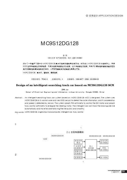
2 硬件系统设计该系统硬件设计主要由MC9S12DG128控制核心、电源管理模块、直流电机驱动模块、转向舵机控制模块、道路信息检测模块、速度检测模块和加速度检测模块等组成,其结构框图如图1所示。
3/2!ᓍ఼ᒜෝ్智能车的控制核心为MC9S12DG128。
MC9S12DG128基于MC9S12DG128单片机的智能寻迹车设计曾 军(四川大学 电气信息学院,四川 成都 610065)摘 要: 设计了一种基于飞思卡尔MC9S12DG128单片机控制的智能寻迹车系统。
该系统以MC9S12DG128为控制核心,采用CCD 图像传感器检测路面信息,利用加速度传感器检测加速度,红外传感器检测速度,采用PID 算法控制智能车直流驱动电机和模糊控制算法控制舵机转向,从而实现智能车快速稳定地寻黑线行驶。
关键定: MC9S12DG128,单片机,智能车,模糊控制中图分类号:TP242.6 文献标识码:A 文章编号:1006-6977(2009)03-0054-03Design of an intelligent-searching track car based on MC9S12DG128 SCMZENG Jun(School of Electrical Engineering and Information, sichuan University, Chengdu 610065, China)Abstract:An intelligent-searching track car system based on MC9S12DG128 MCU is designed. The system uses MC9S12DG128 as its control core and uses CCD sensors to detect the route information, and its acceleration and speed is detected by sensors. The system adopts PID arithmetic to control the DC motor and adopts fuzzy control arithmetic to energize the steering motor. The intelligent car can track the black-guide line automatically and move forward following the line quickly and smoothly.Key words: MC9S12DG128, single-chip microcomputer, intelligent car, fuzzy control图 1系统硬件设计结构框图图 3直流电机驱动电路是飞思卡尔公司生产的一款16位单片机,片内总线时钟可达到25MHz ;片内资源包括8K RAM 、128K Flash 、2K EEP-ROM ;SCI ,SPI ,PWM 和串行接口模块;脉宽调制模块(PWM )可设置成4路8位或2路16位,逻辑时钟选择频率脉宽;2个8路10位A/D 转换器,增强型捕捉定时器并支持背景调试模式等[1]。
基于单片机的智能小车的系统设计
基于单片机的智能小车的系统设计Design of Intelligent Car System Based on MCU基于单片机的智能车设计[摘要]近几年来,智能车辆己成为汽车和智能控制领域的热点研究课题之一。
它体现了自动控制、人工智能、传感技术、机械、计算机等多个学科领域理论技术的交叉和综合,本论文以飞思卡尔智能车大赛光电组为背景而展开。
智能车系统以Freescale 16位微控制器MC9S12XS128作为系统控制处理器,采用基于光电传感器的信号采样模块获取赛道黑线信息,通过PID控制策略和 PWM控制技术对智能车的转向和速度进行控制。
使智能车能够自主识别黑色引导线并根据黑色引导线实现快速稳定的寻线行驶。
本论文分析了智能车系统的设计方案,详细介绍了智能车控制系统的软硬件设计,包括传感器模块、驱动电机模块、舵机转向模块、测速模块等,并详细介绍了软件控制算法的设计,最后,介绍了智能车的整体调整、测试。
调试实验结果表明,智能车系统工作稳定,能较好的满足控制要求。
[关键词]智能汽车;MC9S12XS128;光电传感器;控制算法Design of Intelligent Car System Based on MCUElectrical Engineering and Automation Major SHI Xiao-ying Abstract: In recent years, intelligent vehicles have become a hot research topic of cars and intelligent control area. It embodies the automatic control, artificial intelligence, sensor technology, machinery, computers and many other areas of the intersection of technology and integrated.The intelligent car system, with the Fresscale 16-bitsingle-chip MC9S12XS128 as its control microprocessor, uses signal acquisition module to obtain lane image information, and adopts signal PID control strategy together with PWM technology to have a control on the steering angle and speed of the system. The main function that the intelligent car may achieve is that the car should track the black-guide-line automatically and move forward following the line as fast and stable as possible. This paper gives an overall design blueprint of the intelligent car system, introduce the hardware design including signal acquisition module, power supply module, motor drive module, servo motor module, velocity collection module and etc. and the intelligent car of the mechanical structure and adjustment method. Finally, on the smart car’s overall debugging and testing, the results show the s mart car hardware system stability, better able to meet the requirements of control.Key words: intelligent vehicles; MC9S12XS128; Photoelectric sensor; Control algorithm目录1 引言 (1)1.1 课题背景 (1)1.2 智能技术国内外发展现状 (1)1.3 课题研究的任务 (1)2 整体设计方案 (2)2.1 路径识别传感器的选定 (2)2.2 系统总体框图 (3)3 硬件电路设计 (4)3.1 MCU模块 (4)3.2 电源管理模块 (5)3.3 路径识别模块 (6)3.3.1 光电传感器原理 (6)3.3.2 传感器的选择 (7)3.3.3 激光传感器电路设计 (7)3.4 电机驱动的选型和电路设计 (9)3.5 速度测量模块 (9)3.6 转向舵机控制模块 (10)3.6.1 舵机的控制 (11)3.7 MC9S12XS128的硬件I/O分配 (12)4 系统的软件设计 (12)4.1 系统初始化 (13)4.2 路径识别算法 (14)4.2.1 激光传感器路径识别状态分析 (14)4.2.2 路径识别算法的设计 (17)4.3 转角和速度控制算法 (17)4.3.1 转向舵机控制算法 (18)4.3.2 驱动电机控制算法 (18)4.4 软件设计环境与开发工具 (19)结束语 (21)参考文献 (22)附录部分源程序 (22)致谢 (28)1 引言1.1 课题背景近年来随着汽车工业的迅速发展,关于汽车的研究也就越来越受到大家的关注。
基于飞思卡尔单片机的智能车设计
中文题目:基于飞思卡尔单片机的智能车设计外文题目:FREESCALE MCU-BASED DESIGN OF INTELLIGENT VEHICLE毕业设计(论文)共71页(其中:外文文献及译文5页)图纸共1 张完成日期2013年6月答辩日期2013年6月摘要本设计主要讨论了基于Freescale公司的MC9S12XS128芯片制作的自主巡线智能车的设计方案和原理。
本文将从机械结构设计,硬件电路设计和软件算法设计等几个方面全面介绍智能车的制作及调试过程。
根据第八届“飞思卡尔”杯全国大学生智能汽车竞赛的技术要求,赛车以检测通以20KHZ、100mA的导线的电磁场为基础,通过单片机采集到的磁感应电压信号,实现对赛车的转向控制,进而识别赛道达到路径寻迹的目的。
本设计针对控制要求对智能车模型的机械结构进行设计和调整,同时对智能车运行中产生侧滑的原因进行分析,并对智能车的质量和重心位置进行优化调整。
在硬件方面,系统由控制核心(MCU)模块、电源管理模块、路径识别模块、电机驱动模块、舵机控制模块、速度检测模块以及LCD显示模块等组成。
在软件方面,主要编写了主程序、转速检测程序、电机和舵机驱动程序等相关程序。
本设计在原有智能车系统的基础上,对硬件电路进行了改进,提高了路径检测的前瞻性与抗干扰性。
结果表明,智能车在速度、稳定性和可靠性上都达到良好的状态。
关键词:智能车控制;电磁传感器;路径识别;软件设计AbstractThis design focuses MC9S12XS128 based on Freescale's chip production line inspection autonomous intelligent vehicle design and principles. This article from the mechanical design, hardware design and software algorithm design and other aspects of comprehensive introduction smart car production and debugging process.According to the eighth "Freescale" Cup National Undergraduate Smart Car Competition technical requirements, in order to detect the car pass by 20KHZ, 100mA wire EMF-based microcontroller collected through magnetic induction voltage signal, steering control of the car, thus identify the track reaches the path tracing purposes. The design requirements for the control of the smart car model design and the mechanical structure adjustment, while the smart car running analyze the causes of skidding, and the quality and smart car adjustments to optimize the center of gravity position. In terms of hardware, the system controlled by the core (MCU) modules, power management module, the path identification module, the motor drive module, servo control module, the speed detection module and LCD display modules and other components. On the software side, the main compiled main program, speed detection procedures, motors and servo drivers and other related procedures.The design of the original smart car system, based on the hardware circuit has been improved to improve the prospective path detection and interference. The results show that the smart car in terms of speed, stability and reliability have reached a good state.Key words: Intelligent car control; The electromagnetic sensor; Software Design; Path recognition目录0前言.......................................... 错误!未定义书签。
(毕业设计)飞思卡尔智能车及机器视觉

图像处理在智能车路径识别中的应用摘要机器视觉技术在智能车中得到了广泛的应用,这项技术在智能车的路径识别、障碍物判断中起着重要作用。
基于此,依据飞思卡尔小车的硬件架构,研究机器视觉技术应用于飞思卡尔小车。
飞思卡尔智能车处理器采用了MC9S12XS128芯片,路况采集使用的是数字摄像头OV7620。
由于飞思卡尔智能车是是一款竞速小车,因此图像采集和处理要协调准确性和快速性,需要找到其中的最优控制。
因此本设计主要需要完成的任务是:怎样用摄像头准确的采集每一场的图像,然后怎样进行二值化处理;以及怎样对图像进行去噪处理;最后也就是本设计的难点也是设计的核心,怎样对小车的轨迹进行补线。
本设计的先进性,在众多的图像处理技术中找到了适合飞思卡尔智能车的图像处理方法。
充分发挥了摄像头的有点。
经过小车的实际测试以及相关的MATLAB 仿真,最终相关设计内容都基本满足要求。
小车的稳定性和快速性得到显著提高。
关键词:OV7620,视频采集,图像处理,二值化The Application of Image Processing in the Recognition ofIntelligent Vehicle PathABSTRACTCamera Machine vision technology in the smart car in a wide range of applications, the technology identified in the path of the smart car, and plays an important role in the obstacles to judge. Based on this, based on the architecture of the Freescale car, machine vision technology used in the Freescale car. Freescale smart car the processor MC9S12XS128 chip traffic collected using a digital camera OV7620. Freescale's Smart car is a racing car, so the image acquisition and processing to coordinate the accuracy and fast, you need to find the optimal control. This design need to complete the task: how to use the camera to accurately capture every image, and then how to binarization processing; and how to image denoising; last is the difficulty of this design is the design of the core, how to fill line on the trajectory of the car.The advanced nature of the design found in many image processing techniques of image processing methods for Freescale Smart Car. Give full play to the camera a bit. The actual testing of the car and MATLAB simulation, the final design content can basically meet the requirements. The car's stability and fast to get improved significantly.KEY WORDS: OV7620,Video Capture,Picture Processing,Binarization目录前言 (1)第1章飞思卡尔赛车及机器视觉的概述 (2)1.1 智能车的研究背景 (2)1.1.1 智能车的发展历史 (2)1.1.2 应用前景 (2)1.2 智能车设计要求介绍 (3)1.3 机器视觉介绍 (4)1.4 小结 (4)第2章主要思路及技术方案概要 (5)2.1 总体设计主要方法步骤 (5)2.2 摄像头的对比与选择 (5)2.2.1 摄像头的选取 (5)2.2.2 模拟摄像头 (6)2.2.3 数字摄像头 (6)2.2.4 摄像头的选定 (7)2.3 二值化方案的选取 (7)2.3.1 双峰值法 (7)2.3.2 迭代法 (8)2.3.3 大津法 (8)2.3.4 灰度拉伸-一种改进的大津法 (9)2.3.5 二值化方案的最终选定 (9)2.4对图像进行去噪 (9)2.4.1 传统的去噪法 (9)2.4.2 小波去噪 (11)2.4.3 去噪方法的最终确定 (13)2.5小结 (13)第3章硬件设计 (14)3.1 硬件总体方案设计 (14)3.2 核心控制板 (15)3.3 摄像头的安装 (15)3.4 小结 (16)第4章软件设计 (17)4.1 系统软件总体设计方案 (17)4.2 图像二值化软件设计 (17)4.3 去噪设计 (19)4.3.1 实验信号的产生 (19)4.3.2各参数下去噪效果对比 (20)4.4 二值化后补线 (24)4.5 小结 (32)第5 章结果分析 (33)5.1 采集到的灰度值去噪前的MATLAB仿真 (33)5.1.1 去噪前MATLAB函数和仿真结果 (33)5.1.2 去噪后MATLAB仿真结果 (34)5.2 边界扣取 (35)5.2.1 边界扣取函数 (35)5.2.2 边界扣取仿真结果 (36)5.3 补线后效果 (37)5.4 小结 (38)结论 (39)谢辞 (40)参考文献 (41)附录 (42)外文资料翻译 (45)前言机器视觉技术近几十年来已经得到广泛的应用,并且已经取得了巨大的成功,大大改善了人们的日常生活。
毕业设计(论文)--基于嵌入式stm32的飞思卡尔智能车设计
摘要飞思卡尔智能车大赛是面向全国大学生举办的应用型比赛,旨在培养创新精神、协作精神,提高工程实践能力的科技活动。
大赛主要是要求小车自主循迹并在最短时间内走完整个赛道。
针对小车所安装传感器的不同,大赛分为光电组、电磁组和摄像头组。
本文介绍了本院自动化系第一届大学生智能汽车竟赛的智能车系统。
包括总体方案设计、机械结构设计、硬件电路设计、软件设计以及系统的调试与分析。
机械结构设计部分主要介绍了对车模的改进,以及舵机随动系统的机械结构。
硬件电路设计部分主要介绍了智能车系统的硬件电路设计,包括原理图和PCB设计智能车系统的软、硬件结构及其开发流程。
该智能车车模采用学校统一提供的飞思卡尔车模,系统以STM32F103C8T6作为整个系统信息处理和控制命令的核心,使用激光传感器检测道路信息使小车实现自主循迹的功能关键字:飞思卡尔智能车STM32F103C8T6 激光传感器第一章概述1.1专业课程设计题目基于嵌入式STM32的飞思卡尔智能车设计1.2专业课程设计的目的与内容1.2.1目的让学生运用所学的计算机、传感器、电子电路、自动控制等知识,在老师的指导下,结合飞思卡尔智能车的设计独立地开展自动化专业的综合设计与实验,锻炼学生对实际问题的分析和解决能力,提高工程意识,为以后的毕业设计和今后从事相关工作打下一定的基础。
1.2.2内容本次智能车大赛分为光电组和创新做,我们选择光电组小车完成循迹功能。
该智能车车模采用学校统一提供的飞思卡尔车模,系统以STM32F103C8T6作为整个系统信息处理和控制命令的核心,我们对系统进行了创造性的优化:其一,硬件上采用激光传感器的方案,软件上采用keil开发环境进行调试、算法、弯道预判。
其二,传感器可以随动跟线,提高了检测范围。
其三,独立设计了控制电路板,充分利用STM32单片机现有模块进行编程,同时拨码开关、状态指示灯等方便了算法调试。
1.3方案的研讨与制定1.3.1传感器选择方案方案一:选用红外管作为赛道信息采集传感器。
毕业设计(论文)-基于单片机控制智能小车设计以及英文文献和proteus仿真包括程序
摘要本次设计的单片机控制的智能小车,采用AT89C51单片机为小车的控制核心。
运用L298芯片实现对小车前进、后退、左行、右行、以及全速和减速的控制,同时单片时机自动根据超声波传感器检测到的情况播放相对应的音乐并点亮相对应颜色的LED灯,实现了自动避障和声光报警两大功能。
此外本次设计还运用液晶显示器LCD1602对小车行驶里程和实时日期、时间进行显示。
在液晶显示器的第一行显示根据霍尔元件A44E获得的脉冲数而计算出的小车行驶的里程数;在液晶显示器的第二行显示从时钟芯片DS1302读取的实时日期和时间,实现了液晶显示功能。
由以上各局部共同实现了设计要求的自动避障、液晶显示、声光报警三大功能。
关键词:AT89C51;L298 ;DS1302;液晶显示AbstractThe AT89C51 microcontmller is taken as the control core for the design of an intelligent car in the paper,with the using of L298 chip ,it can control the automatic advance,backward turn left,turn right and with the speed full or slow,also it according to t he case of ultrasonic sensors detected play the corresponding music and light the color-coded leds.Besides,this design uses LCD1602 for car trip mileage and real-time date and time display.The first row of the LCD display the mileage which based on the number of pulses that the Hall element A44E got.The second row of LCD display the date and time which read from the clock chipDS1302.By above all the design request partially realized automatic obstacle avoidance,liquid crystal display, sound-light alarm three major functions.Keyword:AT89C51;L298;DS1302; liquid crystal display目录1 绪论 (1)1.1 研究背景 (1)1.2 选题意义 (1)2 整体方案设计 (3)2.1 整体方案的设计思路 (3)2.2 整体设计的构成图 (3)3 硬件的选择 (5)3.1 电源模块的选择 (5)3.2 电机控制模块中硬件的选择 (5)3.2.1 电机的选择 (5)3.2.2 电机控制模块的选择 (6)3.3 时间与里程显示模块中的硬件的选择 (8)3.3.1 显示器的选择 (8)3.3.2 时钟芯片的选择 (11)3.3.3 里程检测元件的选择 (15)3.4 声光报警模块中的硬件的选择 (16)3.5 障碍检测模块中硬件的选择 (18)3.6 单片机的选择与简介 (18)4 设计所用软件以及模块程序设计 (21)4.1 所用软件的简介 (21)4.1.1 Keil的简介 (21)4.1.2 Protues的简介 (22)4.2 主程序设计 (23)4.3 电机控制程序设计 (24)4.4 声光报警程序设计 (25)4.5 显示程序设计 (27)结论 (29)致谢 (30)参考文献 (31)附录A 文献及翻译 (33)附录B 程序清单 (48)附录C 元件清单 (64)附录D 电路图 (65)1 绪论1.1 研究背景当今世界,传感器技术和自动控制技术正在飞速开展,机械、电气和电子信息已经不再明显分家,自动控制在工业领域中的地位已经越来越重要,“智能〞这个词也已经成为了热门词汇。
基于飞思卡尔单片机的智能汽车设计
基于飞思卡尔单片机的智能汽车设计摘要本智能车系统设计以 MC9S12DG128B 微控制器为核心,通过一个CMOS 摄像头检测模型车的运动位置和运动方向,使用LM1881视频分离芯片对图像进行处理,用光电传感器检测模型车的速度并使用PID 控制算法调节驱动电机的转速和舵机的方向,完成对模型车运动速度和运动方向的闭环控制。
为了提高智能车的行驶速度和可靠性,采用了自制的电路板,在性能和重量上有了更大的优势,对比了各种方案的优缺点。
实验结果表明,系统设计方案可行关键词:MC9S12DG128,CMOS 摄像头,PIDThe Research of Small and Medium-sized Electric Machines in Fuan CityAuthor:Yao fangTutor:Ma shuhuaAbstractFujian Fuan City industry of electric motor and electrical equipment is the one of the most representative phenomenon of industry cluster in Fujian Province mechanical industry. Its output value of small and medium-sized electric machines accounts for 20% of the whole province’s electrical equipment indu stry. The output amount of small and medium-sized electric machines from this region takes up 1/3 of that of the whole nation. Fuan electric motor and electrical equipment industry plays a significant role in the development of local national economy, being considered to be the main growth point of local economy and called "the Chinese electric motor and electrical equipment city ".This paper launched a research on small and medium- sized electric machines in Fuan city from two angles. The first one inferred the situation of Fuan electric machine industrial cluster as well as the analysis of the temporary existed problems, and then propose a few of suggestions on the part of local government. The second part focus on the improvement of the competitiveness of Fuan electric machine enterprises, through the application of Michael Porter's Five Forces Model into the local industry of electric machine, consequently carried out some strategies local enterprises should take.Key Words: small and medium-sized electric machines, Five Forces Model, industrial cluster目录1 绪论 (1)1.1智能车竞赛背景介绍 (1)1.2智能车系统设计思路及方案分析 (2)1.3系统整体设计结构图 (3)2 机械结构的调整与设计 (4)2.1机械安装结构调整 (4)2.2舵机安装方式的调整 (4)2.3摄像头的安装 (5)2.4测速码盘的安装 (5)2.5前轮倾角的调整 (6)2.6地盘高度的调整 (7)2.7齿轮传动机构及后轮差速的调整 (7)3 硬件电路的设计与实现 (8)3.1硬件电路设计方案 (8)3.2硬件电路的实现 (8)3.2.1 以S12为核心的单片机最小系统 (8)3.2.2 主板 (13)3.2.3 电机驱动电路 (18)3.2.4 摄像头 (23)3.2.5 速度传感器 (24)3.2.6 加速度传感器 (24)3.2.7 去抖动电路 (25)4 软件系统设计与实现 (28)4.1软件系统结构方案选择 (28)4.2软件主流程 (28)4.3端口分配 (29)4.4底层驱动程序设计 (30)4.4.1 时钟模块 (30)4.4.2 PWM模块 (31)4.4.3 外部中断模块 (31)4.4.4 ECT模块 (32)4.4.5 AD模块 (32)4.4.6 串口模块 (33)4.4.7 普通IO模块 (33)4.4.8 实时中断 (34)4.5图像信息处理及道路识别程序设计 (34)4.5.1 赛道提取算法 (35)4.5.2 有一定抗干扰和抗反光能力的黑线提取算法 (37)4.5.3 道路识别算法 (39)4.6起跑线识别程序设计 (40)4.7车体控制程序设计 (41)4.7.1 舵机控制算法 (42)4.7.2 速度控制算法 (43)结论 (44)致谢 (45)参考资料 (46)附录 (47)附录A (47)1 绪论1.1 智能车竞赛背景介绍全国大学生飞思卡尔杯智能车竞赛是教育部主办的面向全国大学生的五大赛事之一(另外四个:数学建模、电子设计、机械设计、结构设计)。
基于飞思卡尔单片机的智能车及其调试系统设计
基于飞思卡尔单片机的智能车及其调试系统设计基于飞思卡尔单片机的智能车及其调试系统设计摘要:本文介绍了一种基于飞思卡尔单片机的智能车设计方案,并详细阐述了其调试系统的设计和实现过程。
通过对传感器、驱动器和控制算法的整合与优化,实现了智能车对环境的感知、路径规划和自主导航功能。
调试系统包括软件调试和硬件调试两个方面,通过实验验证了系统的可行性和稳定性。
实验结果表明,该智能车具备了较高的精确性和响应速度,能够在复杂的环境中实现准确导航。
关键词:飞思卡尔单片机;智能车;调试系统;感知;路径规划;自主导航1.引言智能车作为人工智能领域的一个重要应用方向,在交通运输、环境监测等许多领域有着广泛的应用价值。
随着单片机技术的不断发展和普及,基于飞思卡尔单片机的智能车设计方案逐渐成为研究的热点。
本文旨在利用飞思卡尔单片机开发一种具备感知、控制和规划等功能的智能车,并设计相应的调试系统来验证其工作状态和性能。
2.智能车硬件设计智能车的核心是以飞思卡尔单片机为主控制器的控制系统。
该系统由多个模块组成:传感器模块、驱动器模块、通信模块和电源管理模块。
传感器模块用于感知环境,包括超声波传感器、红外传感器等。
驱动器模块用于控制车轮的转动,实现车辆的前进、后退和转向功能。
通信模块用于与外部设备进行数据交互,电源管理模块用于管理车辆的电力供应和充放电管理。
3.智能车软件设计智能车的软件系统主要包括感知模块、控制模块和规划模块。
感知模块利用传感器获取环境信息,并将其转化为数字信号。
控制模块根据感知模块的数据进行判断和决策,控制车辆的运动。
规划模块根据车辆当前位置和目标位置,采用路径规划算法计算最优路径,并通过控制模块实现车辆的导航功能。
4.智能车调试系统设计智能车的调试系统包括软件调试和硬件调试两个方面。
软件调试主要涉及程序的编写、调试和验证,通过仿真、调试和测试等手段,确保软件系统的正确性和稳定性。
硬件调试主要涉及电路连接、传感器的调试和驱动器的测试,通过检查电路连通性、校准感知模块和测试驱动器的工作状况来验证硬件系统的可靠性和性能。
毕业设计-基于单片机控制智能小车设计以及英文文献和proteus仿真包括程序
摘要本次设计的单片机控制的智能小车,采用AT89C51单片机为小车的控制核心。
运用L298芯片实现对小车前进、后退、左行、右行、以及全速和减速的控制,同时单片机会自动根据超声波传感器检测到的情况播放相对应的音乐并点亮相对应颜色的LED灯,实现了自动避障和声光报警两大功能。
此外本次设计还运用液晶显示器LCD1602对小车行驶里程和实时日期、时间进行显示。
在液晶显示器的第一行显示根据霍尔元件A44E获得的脉冲数而计算出的小车行驶的里程数;在液晶显示器的第二行显示从时钟芯片DS1302读取的实时日期和时间,实现了液晶显示功能。
由以上各部分共同实现了设计要求的自动避障、液晶显示、声光报警三大功能。
关键词:AT89C51;L298 ;DS1302;液晶显示Abstract The AT89C51 microcontmller is taken as the control core for the design of an intelligentcar in the paper,with the using of L298 chip it can control the automatic advancebackwardturn leftturn right and with the speed full or slowalso it according to the case of ultrasonicsensors detected play the corresponding music and light the color-codedleds.Besidesthisdesign uses LCD1602 for car trip mileage and real-time date and time display.The first row ofthe LCD display the mileage which based on the number of pulses that the Hall element A44Egot.The second row of LCD display the date andtime which read from the clock chipDS1302.By above all the design request partially realized automatic obstacle avoidanceliquidcrystal display sound-light alarm three major functions.Keyword:AT89C51L298DS1302 liquid crystal display 目录1 绪论1 1.1 研究背景1 1.2 选题意义12 整体方案设计3 2.1 整体方案的设计思路3 2.2 整体设计的构成图33 硬件的选择 5 3.1 电源模块的选择 5 3.2 电机控制模块中硬件的选择 5 3.2.1 电机的选择5 3.2.2 电机控制模块的选择 6 3.3 时间与里程显示模块中的硬件的选择8 3.3.1 显示器的选择8 3.3.2 时钟芯片的选择11 3.3.3 里程检测元件的选择15 3.4 声光报警模块中的硬件的选择16 3.5 障碍检测模块中硬件的选择18 3.6 单片机的选择与简介184 设计所用软件以及模块程序设计21 4.1 所用软件的简介21 4.1.1 Keil的简介21 4.1.2 Protues的简介22 4.2 主程序设计23 4.3 电机控制程序设计24 4.4 声光报警程序设计25 4.5 显示程序设计27结论29致谢30参考文献31附录A 文献及翻译33附录B 程序清单48附录C 元件清单64附录D 电路图65 大学学士学位论文 1 绪论1.1 研究背景当今世界,传感器技术和自动控制技术正在飞速发展,机械、电气和电子信息已经不再明显分家,自动控制在工业领域中的地位已经越来越重要,“智能”这个词也已经成为了热门词汇。
智能车外文文献翻译(中文英文)--毕业设计

智能车外文文献翻译(中文+英文)--毕业设计智能车我们的社会充斥着各种各样的机器智能在过去的世纪我们目睹越来越多日常生活中的苦差事被机器设备解决如洗衣机然而一个既枯燥又危险的保留区域就是日常驾驶汽车2002年120万人死于交通事故这是所有全球21%死亡死因排名第11如果这种趋势继续下去估计从2020年起每一年死于道路交通事故的人将达到850万人事实上美国交通部估计交通事故的整体社会成本每年超过2300亿美元数百或数千辆车共享相同的道路时就导致了大家都熟悉的交通挤塞交通挤塞破坏了我们的生活质量就像空气污染损害公众健康1990年左右公路运输的专业人士开始申请让他们在交通和道路管理于是诞生了智能交通系统ITS 20世纪90年代中后期开始它的系统进行了开发和部署在发达国家旅客今天能够获得旅行条件的信息无论是驾驶自己的车或乘坐公共交通系统随着世界能源危机的持续以及战争和能源-----石油的消耗及汽车饱有量的增加能源在一天一天下降终有一天它会消失的无影无踪石油不是在生资源所以必须在石油耗净之前找到一种代替品随着科技的发展社会的进步有人发明了电动汽车电动汽车将成为人们最为理想的交通工具世界在各各方面的发展都取得丰硕成果尤其是随着汽车电子技术和计算机以及发展迅速的信息时代电子控制技术在汽车上得到了广泛应用汽车上应用的电子装置越来越丰富电子技术不仅用来改善和提高传统汽车电器的质量和性能而且还提高了汽车的动力性燃油经济性可靠性以及废气排放的净化性汽车上广泛使用电子产品不仅降低了成本并且减少维护的复杂性从发动机的燃油喷射点火装置进气控制废气排放控制故障自诊断到车身辅助装置都普遍采用了电子控制技术可以说今后汽车发展主要以机电一体化汽车上广泛采用的电子控制点火系统主要有电子控制燃油喷射系统电子控制点火系统电子控制自动变速器电子控制防滑ABSASR控制系统电子控制悬架系统电子控制动力转向系统车辆动力学控制系统安全气囊系统主动安全带系统电子控制自动空调系统导航系统还有GPS等有了这些系统汽车响应敏捷使用功能强可靠性高既保证发动机动力又降低燃油的消耗而且又满足排放法规的标准汽车是现代人必不可少的交通工具而电动汽车给我们带来无限乐趣外还能给我们劳累一天的身心得以放松就拿自动变速器来说吧汽车在行驶时可以不踩离合器踏板就可以实现自动换档而发动机不会熄火这样有效的提高驾驶方便性减轻驾驶员的疲劳强度自动变速器主要由液力变矩器齿轮变速器油泵液压控制系统电子控制系统油冷却系统等组成电子控制的悬架主要是用来缓冲路面对车身的冲击力以及减少振动保证汽车平顺性和操纵稳定性当汽车行驶在不平坦的道路时汽车能能根据底盘和路面高度自动调整当车高比设置的高度低时就向气室或油缸充气或充油如果是相反就放气或泻油从而保证汽车的水平行驶提高行驶稳定性可变力动力转向系统因能显著改变驾驶员的工作效率和状态所以在电动汽车上广泛使用VDC对汽车性能有着至关重要的作用它能根据需要主动对车轮进行制动来改变汽车的运动状态使汽车达到最佳的行驶状态和操纵性能并增加了汽车的附着性控制性和稳定性除了这些之外4WS4WD的出现大大提高了电动汽车的价值与性能同步提升ABS具有减少制动距离并能保持转向操作能力有效提高行驶方向的稳定性同时减少轮胎的磨损安全气囊的出现在很大程序上保护了驾驶员和乘客的安全大大降低汽车在碰撞时对驾驶员和乘客的缓冲以过到保护生命安全的目的智能电子技术在汽车上得以推广使得汽车在安全行驶和其它功能更上一层楼通过各种传感器实现自动驾驶除些之外智能汽车装备有多种传感器能充分感知交通设施及环境的信息并能随时判断车辆及驾驶员是否处于危险之中具备自主寻路导航避撞不停车收费等功能有效提高运输过程中的安全减少驾驶员的操纵疲劳度提高乘客的舒适度当然蓄电池是电动汽车的关键电动汽车用的蓄电池主要有铅酸蓄电池镍镉蓄电池钠硫蓄电池钠硫蓄电池锂电池锌―空气电池飞轮电池燃料电池和太阳能电池等在诸多种电池中燃料电池是迄今为止最有希望解决汽车能源短缺问题的动力源燃料电池具有高效无污染的特性不同于其他蓄电池其不需要充电只要外部不断地供给燃料就能连续稳定地发电燃料电池汽车FCEV 具有可与内燃机汽车媲美的动力性能在排放燃油经济性方面明显优于内燃机车辆随着计算机和电子产品不断开级换代电动汽车技术也在日趋成熟与完善使得驾驶更安全方便灵活舒适现在电动汽车离普通消费者的距离还很遥远只有少数人在赶赶时髦而已电动汽车真正能够与传统的燃油汽车相竞争今后汽车市场终会被电动汽车和智能汽车所取代这只是时间性的问题这一天终究会来到的ABSGPS4WS4WD以及各种新时代的电子产品与现代高性能汽车默契组合绝妙搭配带给我们无与伦比的精准驾驶舒适性和行驶安全性以AVR 单片机为核心提出了一种智能探测小车的软硬件设计方案系统可以预先设定小车的行走路线能够实现小车与计算机之间的无线通讯通过超声测物和红外测障电路使小车安全行走另外系统通过JTAG 接口在线调试程序软件设计中采用神经网络自学习大大增强了小车的智能化执行元件的伺服系统性能将决定机器人的性能基于AVR 系列单片机并应用积分分离技术设计离散PI 调节器输出PWM 控制信号建立驱动电机的速度伺服控制系统使用AVR - GCC 编译软件开发伺服系统软件设定速度采样频率为2KHz实现对电机速度的实时控制与基于51 系列单片机开发的伺服系统相比本系统所需的外围电路更简单数据处理速度更快实现了机器人响应快速移动平稳该伺服系统的开发尤其适用于智能移动机器人还可以广泛应用于其它智能设备和生产线提出了一种基于AVR 单片机Atmega8 为核心控制器的比赛机器人控制系统通过比赛机器人的特征分析阐述了构成控制系统所需的主控单元电机驱动单元传感检测单元及LCD 显示单元其中详细分析了以MCBL3006S 为核心的伺服电机驱动单元以及关系比赛机器人基本功能实现的循线传感系统及避障传感系统并给出部分程序最后通过实践表明该控制系统开放性好结构简单编程容易智能并高效智能车的避障规则通过对红外传感器的信息进行采集使用二极管D1 发射红外线二极管D2 接收红外信号红外线发射部分不设专门的信号发生电路直接从单片机实现时钟频率既简化了线路和调试工作又能使电路的稳定性和抗干扰能力大大加强经实验验证该系统运行可靠达到了设计要求介绍一种基于CCD 摄像头的路径识别的智能车控制系统设计了硬件结构与方案提出了转向机构的控制策略该智能车能准确实现自主寻迹具备抗干扰性极强稳态误差小等特点智能车系统包括传感器信息采集与处理电机驱动控制算法及控制策略等方面采用激光传感器采集道路信息并反馈给单片机控制系统通过软件进行相关分析处理通过速度反馈和PID 算法控制舵机转向和智能车速度通过实际运行验证本方法使智能车运行稳定可靠其平均速度达到26ms得到比较理想的效果为了综合利用控制模式识别传感器技术汽车电子电气计算机机械等专业领域知识设计实现了一个基于PID 控制算法 CCD 检测系统并采用H C9SDG128 单片机作为主控芯片的智能车系统该系统使用Codewar rio r IDE 集成开发环境作为程序设计的基本软件平台能利用摄像头自动识别路况进行图像处理进而调整方向沿预定轨道前行具有很强的可靠性稳定性快速性扩展性以飞思卡尔杯智能车大赛为研究背景开发了一种智能循迹小车该小车采用光电传感器检测路径获得赛道信息求出小车与黑线间的偏差采用模糊控制对小车的速度进行控制使小车能够自动跟随直道和弯道实践表明采用模糊控制的智能小车在路径识别的精准度稳定性及速度控制上具有明显优势本世纪初期在计算机和信息革命的影响下汽车经历了性能和与驾驶者之间的互动方面最富戏剧性的变革1908年亨利福特T型车的出现体现了汽车设计上的重大突破它不仅开创了轻松更换零件和大量生产的先河而且其用户友好的运作方式让任何人都可以轻松驾驶近90年来类似于福特T型车的简单汽车越来越少汽车迅速成为了一种复杂的移动电脑扮演着领航者护航者甚至第二司机的角色这些新特性不仅改变了我们的驾驶方式还提高了运输服务质量和挽救生命的能力并对美国工业的竞争力提供了支持然而智能车的表现不仅如此相反的使车辆更加智能的这些组件如新信息安全性和自动化技术是作为零配件抵达市场的或作为可选设备或作为售后服务的特殊配件为了提高司机的安全性这些技术不断发展并上市销售但是个别的技术还没有得到整合不能创造出与司机高度协作的完全智能的车辆汽车行业已经意识到并解决了潜在的不协调技术的大量涌入问题但他们的进步受到技术和经济障碍不确定的消费者喜好不完善的标准和准则的阻碍此外无论是传统的汽车制造商或是政府监管机构除非安全问题非常明显都不能控制售后的产品的使用特别是在卡车和公共汽车的使用方面然而还没有一个以人为本的智能车辆试图整合和协调各种技术以解决问题我们也许不仅仅会失去实现新的车载技术的机遇甚至可能会在无意中降低行车的安全性和性能意识到智能车辆的重要性和汽车设计中人为因素所产生的潜在危险之后交通部于1997年启动智能车辆倡议IVI这一举措旨在加快汽车系统的发展和集成用以帮助汽车卡车及巴士司机更安全和有效地操作20世纪80年代的电视连续剧霹雳游侠功能的智能车辆可以跨越颇高的大厦似乎驾驶超音速本身对坏人间谍并有英文用词和管家的个性这款车不仅是聪明但自作聪明虽然在现实世界中的智能车辆将无法飞越站在交通他们将有强大的能力正如所设想的国际疫苗研究所智能车辆将能够提供路线指示感觉对象警告即将发生的碰撞司机自动信号在紧急情况下帮助司机保持警觉并可能最终能够接管驾驶信息和机动车辆的电脑为基础的技术然而是不是新的用途将广泛的汽车电脑开始了旨在提高车辆运行和驾驶员舒适性技术的20世纪80年代这些技术包括电子控制燃油喷射发动机的性能特别是减少汽车排放提高燃油经济性防抱死制动系统以帮助司机保持在湿滑路面控制巡航控制系统以减轻司机的驾驶很长一段乏味而这些技术主要是加强对车辆在车辆技术的最新波其中最感兴趣的是IVI的能力的目的是智能交通旨在加强对驾驶员的能力的系统这些系统包括预警和信息驾驶辅助和自动化技术正如人们具有不同的专业能力不同类型和层次的车载智能车辆技术赋予情报以补充该驱动程序驾驶员信息系统扩大了驾驶员的路线和地点的知识预警系统如防撞技术提高驾驶员的感知能力发生了什么事在周围环境的自动化和驱动技术援助和模拟驾驶者的思想和行动以实际操作或在紧急情况下长时间的车辆暂时的但是在智能车辆将扩大司机的能力它也可能会增加司机的传统角色特别是在新车内的技术中人的作用扩大从感觉运动技能写道托马斯谢里登教授谁负责的人机系统实验室在美国麻省理工学院MIT这一规划程序员在自动化诊断者监控学习者和管理者ITS的研究显示出将在智能车辆中应用的许多技术的好处可行性路线引导系统将帮助司机更好的行驶在不熟悉的街道或找到到达目的地最快的路线1992年和1993年在交通部主办的奥兰多TravTek实地测试中显示配备了路线引导系统的游客驾驶汽车减少了30的车辆转错弯的问题与使用纸质地图的游客相比节省了20的时间防撞系统可以加强交通安全规范完全防止交通事故的发生据研究表明如果司机能多半秒钟反应时间就可以避免60的岔路交通事故和30的迎面相撞而75的车辆事故是由司机走神造成的国家公路交通安全管理局NHTSA估计每年美国应用于这三类的防撞系统能够避免110万次交通事故占总交通事故数的17而这能够挽救17500人的生命安全带和气囊约挽救10500人并挽回260亿美元的损失其他的安全设施正在测试中包括自动撞击告知系统当一辆汽车的安全气囊弹出时该系统会自动发出求救信号而昏睡司机警告系统可以防止在汽车行驶过程中司机昏昏欲睡车内自动化系统可以在紧急情况下接管驾驶或在允许长时间行驶的情况下自动驾驶1996年国家公路交通安全管理局开始实地测试智能巡航控制系统该系统能够自动调整车辆行驶速度与前方车辆保持安全距离以评价这种技术在安全方面的影响更加戏剧化的一幕出现在名为放开手放开脚的驾驶中去年夏天由交通部和其他9个公私营组织合办的全国自动公路系统联盟NAHSC在圣地亚哥I-15号路一段12公里的测试路段示范了未来全自动车辆的原型未来自动公路管理系统将在速度越来越高车距越来越短的高速地段提高交通管理者2-3倍的监管力度该系统也可能消除人为操作错误引发的交通事故的发生提高路段的安全性除了为乘客提供安全和高效的交通以外联邦政府预计智能汽车固有的发展趋势也有可能提高美国的经济竞争能力为了让智能汽车发挥出它最大的潜力它们必须能够与智能交通基础设施系统和其他的智能汽车沟通交流例如与智能基础设施系统沟通可以使智能汽车了解事故的发生然后实时主动地选择路线智能汽车还可以作为探针将有关于路段条件的信息发送给智能基础设施系统用以创建更加丰富的道路条件基本信息此外全自动汽车应当还可以在某种程度上依赖于智能基础设施系统和其他的智能汽车提供的引导例如不久前圣地亚哥的美国直升机协会AHS显示在保险杠下安装有磁动传感器的自动汽车成功被植入路表下方12米的磁铁引导行驶在未来的5到10年我们应该能够看到具有特别驱动信息和报警系统能力的第一代产品随着信息的发展这些系统将日益完善虽然防撞系统会提供一些自动的援助司机们仍然持有汽车的完全控制权此外因为和智能基础设施系统有了初步的沟通能力汽车将在路段条件的实时侦查方面更加智能化约10至15年一些改进措施的应用将为我们带来更好更智能的第二代产品虽然司机仍然有汽车的完全控制权但防撞系统将可以在紧急情况下采取暂时控制另外更加精密的语音识别系统将被纳入司机与汽车的互动方面车辆之间能够互相沟通以提高防撞能力当然与智能基础设施系统的沟通也将更加积极有效大约20年在第三代产品中我们将能看到完全自动化的公路系统车辆和基础设施的整合系统司机与汽车之间更加贴近的互动如视觉增强和平视显示仪的使用回顾一个世纪泛滥如洪的技术汽车作为一项尤为突出的动力学发明而鹤立鸡群在下个世纪这种活力将推动信息和计算机技术的发展我们未来的挑战是整合新的信息安全和自动化技术用以创造以人为本的智能车辆提高安全性地面传动效率和经济竞争能力Intelligent VehicleOur society is awash in machine intelligence of various kindsOver the last century we have witnessed more and more of the drudgery of daily living being replaced by devices such as washing machines One remaining area of both drudgery and danger however is the daily act ofdriving automobiles 12million people were killed in traffic crashes in 2002 which was 21 of all globaldeaths and the 11th ranked cause of death If this trend continues an estimated 85 million people will bedying every year in road crashes by 2020 in fact the US Department of Transportation has estimated the overall societal cost of road crashes annually in the United States at greater than 230 billion when hundreds or thousands of vehicles are sharing the same roads at the same time leading to the all too familiar experience of congested traffic Traffic congestion undermines our quality of life in the same way air pollution undermines public healthAround 1990 road transportation professionals began to apply them to traffic and road management Thus was born the intelligent transportation system ITS Starting in the late 1990s ITS systems were developed and deployedIn developed countries travelers today have access to signifi-cant amounts of information about travel conditions whether they are driving their own vehicle or riding on public transit systems As the world energy crisis and the war and the energy consumption of oil -- and are full of energy in one day someday it will disappear without a trace Oil is not in resources So in oil consumption must be clean before finding a replacement With the development of science and technology the progress of the society people invented the electric car Electric cars will become the most ideal of transportationIn the development of world each aspect is fruitful especially with the automobile electronic technology and computer and rapid development of the information age The electronic control technology in the car ona wide range of applications the application of the electronic device cars and electronic technology not only to improve and enhance the quality and the traditional automobile electrical performance but also improve the automobile fuel economy performance reliability and emissions purification Widely used in automobile electronic products not only reduces the cost and reduce the complexity of the maintenance From the fuel injection engine ignition devices air control and emission control and fault diagnosis to the body auxiliary devices are generally used in electronic control technology auto development mainly electromechanical integration Widely used in automotive electronic control ignition system mainly electronic control fuel injection system electronic control ignition system electronic control automatic transmission electronic control ABSASR control system electronic control suspension system electronic control power steering system vehicle dynamic control system the airbag systems active belt system electronic control system and the automatic air-conditioning and GPS navigation system etc With the system response the use function of quick car high reliability guarantees of engine power and reduce fuel consumption and emission regulations meet standardsThe car is essential to modern traffic tools And electric cars bring us infinite joy will give us the physical and mental relaxation Take for example automatic transmission in road can not on the clutch can achieveautomatic shift and engine flameout not so effective improve the driving convenience lighten the fatigue strength Automatic transmission consists mainly of hydraulic torque converter gear transmission pump hydraulic control system electronic control system and oil cooling system etc The electronic control of suspension is mainly used to cushion the impact of the body and the road to reduce vibration that car getting smooth-going and stability When the vehicle in the car when the road uneven road can according to automatically adjust the height When the car ratio of height low set to gas or oil cylinder filling or oil If is opposite gas or diarrhea To ensure and improve the level of driving cars driving stability Variable force power steering system can significantly change the driver for the work efficiency and the state so widely used in electric cars VDC to vehicle performance has important function it can according to the need of active braking to change the wheels of the car car motions of state and optimum control performance and increased automobile adhesion controlling and stability Besides these appear beyond 4WS 4WD electric cars can greatly improve the performance of the value and ascending simultaneously ABS braking distance is reduced and can keep turning skills effectively improve the stability of the directions simultaneously reduce tyre wear The airbag appear in large programs protected the driver and passengers safety and greatly reduce automobile in collision of drivers and passengers in the buffer to protect the safety of lifeIntelligent electronic technology in the bus to promote safe driving and that the other functions The realization of automatic driving through various sensors Except some smart cars equipped with multiple outside sensors can fully perception of information and traffic facilities and to judge whether the vehicles and drivers in danger has the independent pathfinding navigation avoid bump no parking fees etc Function Effectively improve the safe transport of manipulation reduce the pilot fatigue improve passenger comfort Of course battery electric vehicle is the key the electric car battery mainly has the use of lead-acid batteries nickel cadmium battery the battery sodium sulfide sodium sulfide lithium battery the battery the battery the flywheel zinc - air fuel cell and solar battery the battery In many kind of cells the fuel cell is by far the most want to solve the problem of energy shortage car Fuel cells have high pollution characteristics different from other battery the battery need not only external constantly supply of fuel and electricity can continuously steadily Fuel cell vehicles FCEV can be matched with the car engine performance and fuel economy and emission in the aspects of superior internal-combustion vehiclesic car from ordinary consumers distance is still very far away only a few pAlong with the computer and electronic product constantly upgrading electric car open class in mature technology and perfected that drive more safe convenient and flexible comfortable Now the electreople in bandwagonElectric cars with traditional to compete in the market the car Will was electric cars and intelligent car replaced This is the question that day after timing will come ABS GPS and various new 4WD 4WS electronic products and the modern era excellent performance auto tacit understanding is tie-in bring us unparalleled precision driving comfort and safety of drivingThe hardware and software of the intelligent vehicle are designed based on AVRThis system could set the route in advance The vehicle could communicate with the PC vianRF401 and could run safely with the help of ultra sound detection and infrared measuring circuitNeural network self- study is used to improve the intelligence of the vehicle The performance of servo systems will determine the property of the robot. Based on AVRseries MCUthe velocity servo system for driving motor is created in this paperincluding a discrete PIregulator which will work out a PWM control signal with applying the skill of integral separation. The velocities of motors will be controlled real - time with the speed sampling frequency set for 2KHz by using the AVR - GCC compiler software development. Compared to the servo system development based on the 51 Series MCUthe system here has these advantages of simpler peripheral circuit and faster data processing.The experiments demonstrate thatthe mobile robot runs stably and smoothly by the control of AVR unitsand that the design proposal especially benefits thedevelopment of intelligent mobile robotsalso can be widely used in the development of other smart devices and product lines.A new design of contest robot cont rol system based on AVR Atmega8 was put forward According to the character of contest robot the main cont rol unit motor drive unit sense detection unit and LCDdisplay unit wereintroduced Furthermore the servo driver system based on MCBL3006S the line t racker sensor system and the obstacle avoidance sensor system were presented in detail Finally the performance showsthat the cont rol system is open simple easy programming intelligent and efficiency Avoidance rules of intelligent vehicle obstacle are introducted Through the collection of infrared sensor formation the rules use diode D1 to launch and diode D2 to receive infrared signals Infrared transmitter signal without a dedicated circuit comes directly from the MCU clock frequency which not only simplifie the circuit and debugging but also make the circuit stability and anti- jamming capability greatly enhanced After the experimental verification the system runs reliably meet the design requirementsA smart car control sys tem of the path informat ion identif ied based on CCD camera was introduced The hardware s truc ture and scheme were designed The contro l strategy of s teering mechanismwas presented T he smart car not only can identify the road prec isely but also have antinterference performance and small s teady state errorThis article designed smartcar systemincludes the aspects of the sensor information acquisition and processing motor drive control algorithm and control strategy etcUsing laser sensor to collect the road information which can feedback to the microcontroller control systemthen making analytical processing combined with the softwareWith velocity feedback and PID control algorithms to control steering engine and the speed of smartcarVerified by actual operation this method makes smartcar travel stably and reliablyand its average speed to reach 26m s and get a satisfied resultsBy the aid o f the pro fessio na l know ledge of contr ol patter n recog nitio n senso r t echnolog y aut omotive elect ronics elect ricit y computer machiner y and so on an intelligent vehicle system is designed with PID control a lg orithmCCD detection system and H C9SDG128 M CU Codew arr ior IDE integr ated dev elo pment pro gr amming env ir onment is taken as a basic softw are platform t hat can aut omatically deal w ith the traffic and image pro cessing and then adjust the mo ving direction along the scheduled or bit by t he aid of a CCD camera The system has many advantages such as hig h r eliability high stability good speedability and scalabilityBased on the research background of the Free-Scale smart car competition a smart trackfollowing car is designed In the car the photo electricity sensor is used to check the path and obtain the information。
基于飞思卡尔单片机的智能小车设计与应用毕业论文
安徽建筑大学毕业设计(论文)专业:通信工程班级:09通信1班学生姓名: xxx学号: 006课题:基于飞思卡尔单片机的智能小车设计与应用——主控制电路设计指导教师:2013 年 6 月5日摘要本文的主要内容是利用飞思卡尔公司的32位单片机MPC5604MINI,设计能在特定跑道上循迹行驶的智能小车。
智能车系统以MPC5604MINI为核心,用它来进行信号采集、数据传输与运算等动作,并产生PWM波控制舵机和电机。
整个系统由单片机模块、路径识别模块、速度检测模块、舵机模块、直流电机驱动模块、电源模块等组成。
智能小车的硬件设计包括:双向控制的电机驱动,可同时对多模块供电的电源系统, PWM波形驱动舵机电路,与上位机通信的RS232通信模块等。
关键字:智能小车,MPC5604MINI,主控电路,双向控制。
AbstractThe main content of this paper is to use the 32-bit SCM freescale company mpc5604mini, in particular the runway design can trace the car driving on intelligence. Intelligent car system to mpc5604 as the core, and use it to signal acquisition, data transmission and computing such action and create PWM wave to control the steering gear and motor. The whole system of microcomputer module, path recognition module, speed detection module, steering gear module, dc motor driver module, power supply module.Intelligent car of hardware design including: two-way control motor drive, but at the same time for more power supply module of the power supply system, V PWM waves of steering gear drive circuit, and the upper machine RS232 communication module of communication, etc.Key word: Intelligent vehicles, MPC5604MINI, master control circult, Two-waycontrol.目录11引言 (1)选题意义 (1)国内外概况 (1)国外概况 (1)国内概况 (2)智能车的发展前景 (3)2 系统设计及方案论 (3)系统设计要求 (3)系统设计方案 (3)图系统总框图 (4)主控芯片的选定 (4)传感器模块 (5)测速传感器模块 (5)转向舵机模块 (6)电机驱动模块 (6)3主控芯片中所用模块简介 (6)PWM 模块 (6)PIT模块 (7)I/O模块 (7)SCI模块 (7)4 智能车机械设计及安装 (7)舵机的安装 (8)后轮倾角的调整 (8)前轮差动轮的调整 (9)速度检测模块安装 (9)传感器的安装 (9)5系统电路部分解析 (9)主控芯片电路 (9)外围电路 (11)电源管理模块 (11)速度检测电路 (15)舵机驱动电路 (16)拨码开关电路 (17)RS232通信模块 (17)6软件设计 (18)软件流程简图 (18)软件流程图介绍 (19)该系统的软件设计流程是先通过摄像头对赛道信息进行采集,把采集到的信息通过LM1881进行场分离,同时提取出信息的时钟信号,当场同步信号来到时系统进行图像行同步信号的读取,当读到行同步信号时,将要对图像信息进行逐行扫描,达到指定的行数之后就对图像进行预处理和中值滤波,这里预处理用到的是二值化处理,因为采集的图像是黑白的,只需设置一个合理的阈值,把图像处理成只有黑白两种颜色,便于我们采集到赛道两边的黑线信息,然后再进行中值滤波,把信号采集中出现的椒盐噪声所引起的一些孤立黑点给去除掉,从而可以提取出一条清晰的赛道信息,把赛道信息传给主控芯片,由主控芯片产生一个PWM波,PWM波是一个占空比可调的,再由PWM波去控制转向舵机,从而控制小车的转动方向,双向电动机的转动方向的转动速度也是由PWM 波控制的,最终使小车在赛道上平稳快速的行使。
基于飞思卡尔单片机的智能车控制系统设计

毕业设计(论文)基于飞思卡尔单片机的智能车控制系统设计系别自动化工程系专业自动化班级5060418姓名王皓明指导教师赵一丁2010年6月16日基于飞思卡尔单片机的智能车控制系统设计摘要本文以第四届全国大学生智能车竞赛为背景,介绍了智能赛车控制系统的软硬件结构和开发流程。
该比赛采用组委会规定的标准车模,以Freescale半导体公司生产的16位单片机MC9S12DG128为核心控制器,在CodeWarrior 4.7开发环境中进行软件开发,要求赛车在未知道路上完成快速寻线。
本智能车采用双排光电传感器对赛道进行检测,工作电压能与最小系统工作电压相同,可共用一个电源模块。
通过光电传感器提取获得黑线位置,用PID方式对舵机进行反馈控制。
同时通过速度传感器获取当前速度,实现速度闭环控制,根据赛道类型预判信息和当前速度信息对速度进行合理控制。
整个硬件系统包括车模机械结构调整、稳压电源设计、核心控制电路板设计、后轮电机驱动模块设计和上位机通信设计等等。
经过查看各种相关资料,对硬件进行了大量的优化,如针对对各种稳压芯片的测试,确定最优电源电路;测试各种测速方式,最终选用光电管作为测速模块;并在智能车调试过程中不断改进机械结构,使小车运行更加稳定、迅速。
软件系统包括程序初始化、数据采集和车体控制的算法。
为了提高智能赛车的行驶速度和可靠性,经过多次机械结构调整及电路板设计,并经过不断试验,最终确定了现有的系统机械结构和各项控制的PID参数。
关键词:MC9S12DG128 ,智能车,双排光电传感器,PIDIntelligent vehicle control system design based on freescale MCUAuthor :Wang HaomingTutor :ZhaoYidingAbstractBased on the 4th China university of intelligent car race for background, introduces the hardware and software of the control system of intelligent car structure and development process. The game using the standards prescribed by the organizing committee to Freescale semiconductor company models, the production 16-bit single chip MC9S12DG128 for core controller, in CodeWarrior 4.7 development environment in software development and requirement on the road on unknown quick line.This intelligent vehicle using double row of photoelectric sensor, voltage can work with minimal systems can share the same voltage, a power supply module. Through the intelligent vehicle, with black extracted on the way to the PID feedback control. And through the velocity sensor for current velocity, realize speed closed-loop control circuit, according to the type of information and the speed of anticipation to speed control information. The hardware system including mechanical models ,structure adjustment, manostat design, the core control circuit design, rear motor driver module design and computer communication design etc. After check all relevant information on the hardware, the large amounts of optimization, such as all kinds of pressure in the test chip and the optimum power supply circuit, Testing various ways, finally chooses phototube module as a type of cell, And in the intelligent vehicle commissioning process improvement, the mechanical structure is more stable operation, quick. Software system including the initial procedure, the data acquisition and control algorithm. In order to improve the speed of intelligent cars and reliability, and after many mechanical structure adjustment and circuit design, and finally determined through continuous test, the existing system of the mechanical structure and PID control parameters.Key words:MC9S12DG128, intelligent vehicle, double row photoelectric sensor, PID目录1 绪论 (1)1.1智能车的背景及意义 (1)1.2智能车竞赛的研究现状 (2)1.2.1 国外智能车竞赛现状 (2)1.2.2 国内智能车竞赛现状 (3)1.3本文的概况及结构安排 (7)2 智能车方案设计 (8)2.1智能车设计的基本要求 (8)2.2智能车的双排传感器循迹策略方案设计 (8)2.2.1 双排传感器的优势 (8)2.2.2 传感器阵列布局 (9)2.2.3 直道识别方式控制策略 (9)2.2.4 直线稳定控制策略 (13)2.2.5 弯道控制策略 (13)2.2.6 实测结果和现象分析 (14)2.3车模参数 (15)3 硬件设计 (18)3.1智能车整体结构 (18)3.2MC9SDG128B的最小系统及接口设计 (19)3.3电源管理及分布 (20)3.4光电传感器布局 (21)3.4.1 赛道识别传感器模块 (21)3.4.2 测速模块 (22)3.5电机驱动模块 (23)3.6舵机驱动模块 (24)3.7拨码开关模块 (25)4 机械结构调整 (27)4.1一些重要参数对赛车的影响 (27)4.2车模底盘参数调整 (28)4.3重心位置对汽车性能的影响 (30)4.4汽车侧滑的处理 (31)4.5底盘离地间隙 (32)4.6齿轮传动间距调整 (32)4.7后轮差速机构调整 (32)5 智能车软件开发环境及软件设计 (34)5.1智能车软件开发环境 (34)5.1.1 软件调试软件Code Warrior (34)5.1.2 无线调试模块 (36)5.2软件设计 (37)5.2.1 初始化模块 (37)5.2.2 智能车系统的控制策略的设计及实现 (41)5.2.3 PID参数的整合 (45)结论 (48)致谢 (50)参考文献 (51)附录 (52)附录A:智能车硬件连接图 (52)附录B:智能车最终实物图 (53)附录C:PID CONTROLLER (54)1 绪论1.1 智能车的背景及意义智能车系统以迅猛发展的汽车电子为背景,涵盖了控制、模式识别、传感技术、电子、电气、计算机、机械、车辆运动学等多个学科;主要由路径识别、角度控制及车速控制等功能模块组成。
- 1、下载文档前请自行甄别文档内容的完整性,平台不提供额外的编辑、内容补充、找答案等附加服务。
- 2、"仅部分预览"的文档,不可在线预览部分如存在完整性等问题,可反馈申请退款(可完整预览的文档不适用该条件!)。
- 3、如文档侵犯您的权益,请联系客服反馈,我们会尽快为您处理(人工客服工作时间:9:00-18:30)。
毕业设计(论文)任务书课题名称:基于飞思卡尔单片机的智能车设计完成期限:2009年12月 1日至2010年 5月 10日一、课题训练内容通过以全国大学生“飞思卡尔”杯智能车竞赛为背景,设计一台能够自主循迹的小车。
整个开发中,严格执行“飞思卡尔”杯智能车竞赛的比赛规则。
二、设计(论文)任务和要求(1)查阅课题相关参考文献、技术资料,做好备份,以便以后查找;(2)充分分析相关素材,比较多个方案,选择一种完成设计任务;(3)分析和选取完成任务的技术途径和实施方法,第四周前上交毕业设计开题报告一份。
开题报告内容与学校模板要求一致,字数不少于2000字;经指导老师检查合格后才能进行后续工作;(4)补充必要的理论和技术知识,查找相关的元件、器件的参数资料;(5)给出详细的系统设计说明书,画出原理电路图,分析各部分电路功能及原理;(6)根据系统要求,进行硬件设计以及理论数据计算,给出相关参数;(7)根据系统要求,给出系统控制的流程图,编写详细程序;(8)根据系统要求,制作实物和安装调试;(9)撰写毕业设计论文,内容和格式按学校要求执行,(具体要求在学校教务网的下载专区下载:设计论文规范、格式模板、任务书、开题报告、成绩记录等9个文件)。
三、毕业设计(论文)主要参数及主要参考资料主要参数:(1)赛道为普通白色板,宽度为60cm,赛道正中间为2.5cm的黑色普通胶带,铺设赛道地板颜色不作要求,它和赛道之间可以但不一定有颜色差别,跑道最小曲率半径不小于 50 厘米,跑道可以交叉,交叉角为90 °,赛道有一个长为1米的出发区,计时起始点两边分别有一个长度10厘米黑色计时起始线,赛车前端通过起始线作为比赛计时开始或者结束时刻。
(2)须采用飞思卡尔半导体公司的 8 位、 16 位处理器 ( 单核 ) 作为唯一的微控制器,推荐使用 9S12XS128 ,9S08AW60 微控制器;(3)比赛车模采用官方规定的本成品车模;(4)模型车的电源采用官方的7.2V/2000mA的电池,舵机采用制定的s3010;(5)车模改装完毕后,尺寸不能超过:250mm 宽和400mm长;参考资料:[1] 谭浩强.C程序设计(第三版).北京:清华大学出版社.2006.3[2] 卓晴,黄开胜,邵贝贝.学做智能车——挑战“飞思卡尔”杯.北京:北京航空航天大学出版社. 2007年3月[3] 刘瑞新主编 Protel DXP实用教程北京:机械工业出版社.2003[4] 王威等编著 HCS12微控制器原理及应用北京:航空航天大学出版社.2007[5]刘林,杨理,龙叶虹.重庆邮电大学AUTO-2第二届全国大学生智能汽车竞赛技术报告.四、毕业设计(论文)进度表武汉纺织大学毕业设计(论文)进度表注:1.本任务书一式两份,一份院(系)留存,一份发给学生,任务完成后附在说明书内。
2.“实际完成情况”和“检查人签名”由教师用笔填写,其余各项均要求打印,打印字体和字号按照《武汉纺织大学毕业设计(论文)规范》执行。
武汉纺织大学毕业设计(论文)开题报告摘要本文详细介绍了一套智能车的寻线设计方案。
由总到分的先从整体上介绍了该系统的硬件和软件设计思想,继而细分各模块详尽介绍具体设计。
该智能车系统以MC9S12XS128B 作为整个系统信息处理和发出控制命令的核心,基于摄像头采集的赛道信息,提取出黑线中心位置,并求得小车偏离黑线的程度,区分出道路形状,对此信息进一步处理以控制舵机的转向,通过速度传感器获得实时速度信息,利用增量式数字PID 控制算法实现闭环反馈控制。
文章详细介绍了图像采集模块、速度采集模块等信息采集模块和电机驱动模块和舵机驱动模块等动作执行模块的方案选取和电路设计原理,还介绍了系统调试方法策略。
测试表明,该智能车能够很好的跟随黑色引导线,可以实现对应于不同形状的道路予以相应的控制策略,可快速稳定的完成的整个赛道的行程。
关键字:Freescale;单片机;摄像头;速度传感器; PIDABSTRACTThis article brings a complete model of intelligent car design which follows the black line closely and also describes the process of detail of the design. From the whole to detail, we introduce the design method of the hardware and software, and then we present every module of the model at large.The intelligent car system, with single-chip MC9S12DG128 as its information management and sending out control command center, uses image-sensor module based on camera to obtain lane image information, then abstract the black line on the contest lane, and calculates the position difference between the car and the black line, distinguishes the different shape of the lane, then we analyze and deal with the information farther to control the steering angle. This article introduces the scheme selection and the circuit design theory of the information collection module which comprises the image collecting module and speed collecting module and action executing module which includes the motor drive module and steer drive module.The experimental evaluation indicates that the model car is able to follow the black line on the lane closely, realize the function that it executes corresponding control strategy toward different shape lane, and accomplishes the whole journey fast and steadily.Key words:Freescale;Single-chip;micro camera;speed sensor;PID目录1.引言 (1)1.1 发展现状 (1)1.2 方案简介 (1)1.3 文章结构 (2)2.系统整体框架 (2)2.1 系统整体框架 (2)2.2 系统硬件参数 (3)2.3 车模外形 (4)3.模块的基本方案及论证 (4)3.1 图像采集模块 (4)3.2 速度采集模块 (5)3.3 电机驱动模块 (6)3.4 舵机驱动模块 (7)3.5 电源管理模块 (7)3.6 调试模块 (7)3.7 最终决策方案 (7)4.机械结构调整 (8)4.1 总体机械结构 (8)4.2 摄像头的安装 (8)4.3 系统PCB 板的安装 (9)4.4 稳定性调整 (9)4.4.1 主销后倾角 (9)4.4.2 前轮前束 (10)4.5 底盘抬高策略 (10)4.5.1 后轮底盘升高 (10)4.5.2 后轮位置的固定 (11)4.5.3 前轮底盘升高 (11)5. 信息采集模块 (11)5.1 摄像头及其采集电路设计 (12)5.1.1 摄像头简介 (12)5.1.2 摄像头的工作原理 (12)5.1.3 摄像头路径识别原理 (17)5.1.4 摄像头的选取 (18)5.1.5 摄像头提取信号 (19)5.1.6 摄像头的安装 (19)5.2 速度检测电路 (20)6.执行模块电路设计 (20)6.1 电机驱动电路 (20)6.2 舵机 (21)7. 电源模块 (22)7.1 总体电源电路 (22)7.2 单片机等5V 稳压芯片的选择 (23)7.2.1 芯片的选择 (23)7.2.2 电路实现 (23)7.3 CMOS 摄像头用电源 (24)7.4 舵机电源 (24)8 系统软件设计 (25)8.1 概述 (25)8.2 整体过程 (25)8.3 MCU 简介 (25)8.4 系统初始化 (26)8.4.1 摄像头初始化 (26)8.4.2 PWM初始化 (26)8.4.3 超频设置 (27)8.5 图像采集和黑线提取 (27)8.5.1 图像采集 (27)8.5.2 黑线提取 (29)8.6 速度控制 (30)8.6.1 速度控制介绍 (30)8.6.2 简单沿线行驶策略 (31)8.6.3 最佳行驶路线策略 (31)8.6.4 速度获取 (33)9 开发工具、制作调试过程 (33)9.1 软件开发平台Codewarrior IDE (33)9.1.1 Codewarrior IDE 功能介绍 (33)9.1.2 Codewarrior IDE 基本使用方法 (33)9.2 辅助调试方法 (35)10 结论 (35)参考文献 (37)附录 (38)外文资料 (55)中文翻译 (64)致谢 (73)1 引言1.1 发展现状智能汽车,是一种集环境感知、规划决策、自动行驶等功能于一体的综合系统,集中地应用到自动控制、模式识别、传感器技术、汽车电子、电气、计算机、机械等多个学科,是典型的高新技术综合体,具有重要的军用及民用价值。
目前,智能车领域的研究已经能够在具有一定标记的道路上为司机提供辅助驾驶系统甚至实现无人驾驶。
这些智能车的设计通常依靠特定道路标记完成识别,通过推理判断模仿人工驾驶进行操作。
通常,智能车接受辅助定位系统提供的信息完成路径规划,如由GPS 等提供的地图,交通拥堵状况,道路条件等信息。
1.2方案简介按照课题要求,需要制作出一个能够自主识别道路并行驶的智能车模。