EPO物控操作手册
ePush-Lock操作和安装说明书

Operating and Installation InstructionsePush-LockContentGeneral Information (4)Safety (4)2.1.Intended use (4)2.2.Operating conditions (5)2.3.Basic safety instructions (5)2.3.1.Avoid electric shock (5)2.3.2.Avoid injuries (5)2.3.3.Avoid damage to device (5)2.4.Personnel qualifications (5)2.5.Personal protective equipment (6)Description (6)Design (7)Spacers (8)Emergency release (9)6.1.Delivery status for ePush-Lock versions 3000-U600-01, 3000-U600-02 and 3000-U600-05 (9)6.2.Delivery status for ePushLock versions 3000-U600-03 and 3000-U600-04 (10)6.3.Opening from the inside (12)Electrical data and connections (13)7.1.Power supply and output (13)7.2.Connection plug and cable assignment (13)7.3.Open Collector Outputs (13)Control and signal sequences (14)8.1.Version for push button control (14)8.2.Version for toggle switch (15)8.3.Version for central locking (16)Assembly (17)Data sheet (21)General InformationThese instructions will help to securely install the ePush-Lock. In the following, the ePush-Lock is called “device”.These instructions are part of the device.Always keep these instructions with the device.Include these instructions when you sell the device or pass it on in any other way.Manufacturer addressEMKA Beschlagteile GmbH & Co. KGLangenberger Strasse 3242551 Velbert, GermanyPhone: +49 2051/273 0Fax: +49 2051/273 128E-Mail:************Authorized representative for the documentationMr. Sebastian GeckEMKA Beschlagteile GmbH & Co. KGLangenberger Strasse 3242551 Velbert, GermanyPhone: +49 202/7496 462Fax: +49 202/7496 468Safety2.1. Intended useThe ePush-Lock has been designed for locking storage space flaps and doors on motorhomes, recreational vehicles and caravans. The use in other applications can only be approved on request by EMKA Beschlag-teile GmbH & Co. KG. and requires a precise description of the intended use.When using the ePush-Lock, a maximum distance of 800 mm between the individual locking points (fixing points) is recommended.Each application must be validated and checked as a complete system by the manufacturer / distributor for satisfactory and sufficient safety and usability.Use in vehicles requires active electronic locking. The vehicle may only start moving if this safe condition is ensured by the vehicle control system (for example, central locking system or ignition interruption) before driving off.2.2. Operating conditionsMake sure that the device is only used under the following environmental conditions:Temperature: -20 °C to +60 °CRelative humidity: 15% to 85%, non-condensingThe device meets the requirements of protection class IP2x.2.3. Basic safety instructions2.3.1. Avoid electric shockElectrical shock possible when connecting the device.Make sure that the device is only connected by qualified electricians.Make sure that the conditions at the installation location correspond to the protection class of the device. The protection class can be found in the technical data.Before connecting, ensure that all electrical power is switched off.Do not put any visibly damaged device into operation.2.3.2. Avoid injuriesAvoid injury to eyes from drilling dust when drilling holes.Wear safety glasses.2.3.3. Avoid damage to deviceAvoid damage to the electrical connection cable due to kinks.Lay the connection cable to the device so that it is not kinked or squeezed.Avoid damage to the device due to excessive torque when fastening.Tighten screws and nuts with max. 1.5 NmAvoid damage to the device due to moisture.Make sure that the conditions at the installation location correspond to the protection class of the device.The protection class can be found in the technical data.2.4. Personnel qualificationsPeople who assemble or connect the device must have the following skills:Determine visible damage of the device before installationFasten screws or nuts with specified torqueIdentify hazards that may occur when handling electrical equipment and avoid hazardsEstablish electrical connections in accordance with applicable regulations and guidelines (electrical specialist)2.5. Personal protective equipmentWear suitable personal protective equipment when working with the device.When compiling personal protective equipment, observe and follow the regulations at the place of use. Wear safety glasses when drilling holes.Wear hearing protection when drilling holes.DescriptionThe concealed locking device ePush-Lock can keep a door mechanically closed and additionally lock it electronically. Open collector outputs are available for remote monitoring of door status (open/closed) and locking status (unlocked/locked). In case of a status change, the electrical signal changes between the voltage connected to the open collector via external resistor (typically the operating voltage Vcc for the lock) and GND.To lock a door, it must be manually closed first. The output for “Door Status” will change from Vcc to GND. Then the signal to lock the door must be applied. A locking bolt in the ePush-Lock travels into the position “locked” and prevents the door from being opened. The output “Lock Status” changes from Vcc to GND.To open the door again, the signal for to unlock must be applied. The locking bolt in the ePush-Lock travels back to position “unlocked”. The output “Lock Status” changes back to Vcc. The door can then be opened manually again. The output "Door Status" changes back to Vcc.If the signal to lock the door is given while the door is open, the locking bolt tries to travel into the "locked" position. Since this is not possible, it travels back to the position "unlocked".DesignEjectorFrame moduleMounting pointsDoor moduleMounting pointsSpacerSpacersDelivery statusOptional13 mmOptional:Spacer3000-112-25 for 13mm Different height upon request Optional:Spacer3000-112-11 for 13mm, Different height upon requestEmergency release6.1. Delivery status for ePush-Lock versions 3000-U600-01, 3000-U600-02 and 3000-U600-05An emergency release is necessary if thedoor has been electrically locked andelectrical unlocking is not possible.Locking boltFor emergency unlocking, the locking bolt is pulledin the direction of the arrow until it engages. Thiscan be done manually or via Bowden cable.A Ø 6mm eyelet is provided to connect a Bowdencable.After opening the door,the clip must be pushedback, so that the lockingbolt returns to itsoriginal position.6.2. Delivery status for ePushLock versions 3000-U600-03 and 3000-U600-04For emergency release, the red emergencyopening slider is pulled in the direction of thearrow until it engages. This can be donemanually or via a Bowden cable.A Ø 6mm eyelet is provided to connect aBowden cable.After opening the door, the clip must bepushed back. Then the emergency openingslider must be pushed back, so that thelocking bolt can return to its originalposition.Pull direction StandardOptional:Emergency opening slider 3000-112-18Pull direction Optional6.3. Opening from the insideIn the emergency or electrically unlocked state, pull in the marked area to open the door.Electrical data and connections7.1. Power supply and outputSupply voltage: 9 ... 32 VDC, 500 mAOutputs: Open collector, max. 32 V, 50 mA7.2. Connection plug and cable assignmentThe connection cable with the EMKA art.-no. 3000-11 can be used.Alternatively, the following components are required on the ePush-Lock side for customized connecting cables:1 x Connector type MATE-N-LOK (1445022-8)8 x socket contact 1-795606-17.3. Open Collector OutputsFor the evaluation of the Open Collector Outputs, an external resistor R ext 1kΩ ... 15kΩ according to thefollowing circuit diagram must be connected.Versions "push button”, “toggleswitch” and central locking withcontinuous current (same voltagelevel for locking and unlocking)Version for central locking# Color Function Function1 White Input “Lock” Input “Lock”, Channel 12 Brown Input “Unlock” Input “Unlock”, Channel 23 Yellow - -4 Red Vcc -5 Green GND GND6 Grey -7 Pink Output “Lock Status“ Output “Lock Status“8 Blue Output “Door Status" -Control and signal sequences8.1. Version for push button controlInitial state "Open door"Open Collector Outputs "Status Door" and "Status Lock" are on Vcc level.Door is closed manuallyOpen Collector Output "Status Door" changes to GND.Locking the doorThe "Lock" button must be pressed briefly. The locking bolt travels to the position "locked", the Open Collector output" Lock Status" changes to GND level. The door is securely locked.Door lockedOpen Collector Outputs "Status Door" and "Status Lock" are on GND level.Unlock the doorThe "Unlock" button must be pressed briefly. The locking bolt moves to the position "unlocked", the Open Collector Output "Status Lock" changes to Vcc. The door is still closed but unlocked.Opening the doorBy pressing on the door in the lock area, it can be opened. The Open Collector Output "Status Door" changes to Vcc.Special case "Lock open door"If the "Lock" button is pressed briefly while the door is open, the locking bolt tries to travel into the position "locked". Since this is not possible, it travels back to the position "unlocked".Another special case arises in connection with the emergency release if the locking bolt is pulled when the door is locked. Then the locking bolt automatically moves to the unlocked position. The door can then be opened and closed as required.8.2. Version for toggle switchInitial state "Open door"The Open Collector Outputs "Door Status" and "Lock Status" are on Vcc level. The toggle switch“Lock/Unlock” is in position “Unlock”.Door is closed manuallyOpen Collector Output "Door Status" changes to GND level.Locking the doorThe toggle switch must be switched from the "Unlock" to the "Lock" position. The locking bolt moves to the "locked" position, the Open Collector output "Lock Status" changes to GND. The door is securely locked. Door lockedDie Open Collector Outputs " Door Status" and "Lock Status" are on GND level.Unlocking the doorThe toggle switch must be switched from position "Lock" to position "Unlock". The locking bolt moves to the "unlocked" position, the Open Collector Output "Lock Status" changes to Vcc. The door is still closed but unlocked.Opening the doorBy pressing on the door in the lock area, it can be opened. The Open Collector Output "Door Status" changes to Vcc.Special case "Lock open door"If the toggle switch is switched from position "Unlock" to "Lock" position while the door is open, the locking bolt first tries to travel into the "locked" position. Since this is not possible, it travels back to the position "unlocked". If the door is then closed again and shall also be locked, the switch must first be set to the "Unlock" position. After that, the door can be locked again as described above.Another special case arises in connection with the emergency release. If the locking bolt is pulled while the door is locked, the locking bolt automatically travels to the unlocked position. The door can then be opened and closed as required.8.3. Version for central lockingInitial state "Open door"The Open Collector outputs "Door Status" and "Lock Status" are on Vcc level, the two control inputs channel 1 and channel 2 are on GND.Door is closed manuallyOpen Collector Output "Door Status" changes to GND.Locking the doorControl input channel 2 must be switched to Vcc for at least 5 seconds, then back to GND. The locking bolt travels to the position "locked", the Open Collector output "Lock Status" changes to GND. The door is securely locked.Door lockedOpen Collector Outputs "Door Status" and "Lock Status" are on GND.Unlock the doorThe control input channel 1 must be switched to Vcc for at least 5 seconds, then back to GND. The locking bolt moves to the position "unlocked", the Open Collector output "Lock Status" changes to Vcc. The door is still closed but unlocked.Opening the doorBy pressing on the door in the lock area, it can now be opened. The Open Collector output "Door Status” changes to Vcc.Special case "lock open door"If channel 2 is switched to Vcc when the door is open, the locking bolt tries to travel into the "locked" position. Since this is not possible, it travels back to the position "unlocked".Another special case arises in connection with the emergency release. The locking bolt is pulled while the door is locked, and the door is opened. Then the locking bolt is pushed back into its original position and the door is closed again. The door will be the locked state again.Assembly1. StepThe frame unit and the spacer (optional) are mounted on the frame.In some cases, the sealing profile lip must be cut-out for to mount frame unit / spacer.2. StepTo mount the frame unit on the frame, the optimal position must be determined first.The holes for the screws can be marked through the screw points of the frame unit.3. StepThe frame unit is mounted at the screw-on points on the frame.The screws are not included in the scope of delivery and must be selected according supporting surface.FrameSealing ProfileSpacerDoorFrameDoorFrameDoor4. StepA subsequent correction of the position is only possible on the y-axis in the range ± 3mm.5. StepAfter the frame unit has been mounted, the position of the screws on the door can be marked with the assembly aid.For this purpose, the assembly aid is attached to the frame unit and then the door is pressed on.7 9 . Step:Step 10:FrameDoor FrameDoor1. Attach the assembly aid2. Push inpins6. StepThe pointed screw ends of the assembly will leave indentation points on the door.Step 7The door unit can be mounted to the indentation points on the door.8. StepA subsequent correction of the position is possible on the x and y axes in the range ± 3 mm each.The screws are not included in the scope of delivery and must be selected according supporting surface.FrameDoorFrameDoorFrameDoor9. StepThe gap between the frame and door unit should be 1 ... 2 mm. The ePush-Lock is designed for a min. door width of approx. 350 mm. The min. door width depends on the profile design and the position of the hinge. Therefore, the function should always be checked in individual cases. On request, the locking pin can be extended so that the gap increases to max. 6 mm. With the extension of the locking pin, the static tensile strength is reduced.10. StepOptionally, ejectors can be used.For this purpose, the designated areas must be opened in the spacer to insert the ejectors.11. StepOne or two ejectors can be mounted. No additional screws are required for fastening.Areas for ejectors21Data sheetSupply voltage 9 ... 32 VDC, 500 mAOutputs Open collector max. 32 V, 50 mALife cycle test10,000 cycles (0005 / 2020) Ambient temperature range -20°C to +60°C(0037 / 2020)ProtectionIP 20 met (0158 / 2020)Maximum static tensile strength F max. 530 N at 1…2 mm gap (0157 / 2020) 395 N at max. 6 mm gap (0357 / 2021) Tightening torque M max. 1,5 Nm (0156 / 2020)Tightening torqueM max.1,5 NmCylinder screws DIN 912 – M5 were used to determine the torque. These are not included in the scope of delivery. (0156/ 2020) Tightening torque M max.1,5 NmCylinder screws DIN 912 – M5 were used to determine the torque. These are not included in the scope of delivery. (0156 / 2020) Tightening torque M max.1,5 Nm (0156 / 2020)The test results obtained refer exclusively to the test object during the test period under laboratoryconditions. The test results apply exclusively to the use of the product with intended use and taking into account all dependent functional features in an existing system. When using the product in a non-intended application, the determined properties are by no means transferable to the system.411 234324 1。
Epos消费管理系统使用功能性说明书

Epos 消费管理系统使用手册版本:4.1日期:2013 年 6 月适用机型:黑白屏消费机、彩屏消费机。
内容介绍本文档主要介绍了Epos 消费管理系统的使用说明。
包括软件的安装/卸载、软件的介绍和具体的使用方法等。
重要申明首先感谢您选择本消费管理系统。
在使用前,请您仔细阅读本产品的说明书。
本公司提醒您正确使用,将得到良好的使用效果和验证速度。
非经本公司书面同意,任何单位和个人不得擅自摘抄、复制本手册内容的部分或全部,并不得以任何形式传播。
本手册中描述的产品中,可能包含本公司及其可能存在的许可人享有版权的软件,除非获得相关权利人的许可,否则,任何人不能以任何形式对前述软件进行复制、分发、修改、摘录、反编译、反汇编、解密、反向工程、出租、转让、分许可以及其他侵权软件版权的行为,但是适用法禁止此类限制的除外。
由于产品的不断更新,本公司不能承诺实际产品与该资料一致,同时也不承担由于实际技术参数与本资料不符所导致的任何争议,任何改动恕不提前通知。
Epos 消费管理系统使用手册说明:•所有功能都以实际产品为准,由于产品的不断更新,本公司不能承诺实际产品与该资料一致,同时也不承担由于实际技术参数与本资料不符所导致的任何争议,任何改动恕不提前通知。
•本手册中以★说明的功能是某些特定产品的,请以实际产品的菜单为准。
目录一、软件使用前的准备.................................................................................. - 1 -1.1 软件的安装.................................................................................... - 1 -1.1.1 消费软件EPOS 与MSDE 数据库的安装............................ - 1 -1.1.2 指纹驱动程序的安装★...................................................... - 10 -1.1.3 ID 发卡器的安装................................................................. - 14 -1.2 消费软件的启动........................................................................... - 15 -1.2.1 运行ID 消费系统................................................................ - 15 -1.2.2 运行ID 消费系统后台服务................................................. - 17 -1.2.3 运行IC 消费系统................................................................ - 20 -1.3 消费软件的快速使用................................................................... - 23 -1.3.1 资料设定............................................................................ - 23 -1.3.2 消费管理............................................................................ - 23 -1.3.3 设备管理(仅IC 消费软件)............................................ - 25 -1.3.4 卡片中心............................................................................. - 25 -1.3.5 系统管理............................................................................. - 28 -1.3.6 导航..................................................................................... - 28 -1.4 名词解释...................................................................................... - 31 -二、消费软件介绍........................................................................................ - 33 -2.1 主窗口.......................................................................................... - 33 -2.2 资料设置...................................................................................... - 35 -2.2.1 公司注册............................................................................ - 36 -2.2.2 设备登记(仅ID 消费软件)............................................ - 37 -2.2.3 其他资料............................................................................ - 43 -2.2.4 卡类资料............................................................................ - 50 -2.2.5 部门资料............................................................................ - 52 -2.2.6 人事资料............................................................................ - 53 -2.2.7 离职管理............................................................................. - 58 -2.2.8 餐厅资料............................................................................ - 62 -2.2.9 餐别资料............................................................................ - 63 -2.2.10 消费机资料...................................................................... - 64 -2.2.11 系统参数.......................................................................... - 69 -2.3 卡务中心结算.............................................................................. - 72 -2.3.1 充值明细............................................................................ - 73 -2.3.2 消费明细............................................................................ - 74 -2.3.3 卡余额表............................................................................ - 75 -2.3.4 退款明细表........................................................................ - 75 -2.3.5 卡成本明细表..................................................................... - 76 -2.3.6 退卡明细表........................................................................ - 77 -2.3.7 出纳统计帐管理和收支统计账管理................................... - 78 -2.4 消费结算..................................................................................... - 81 -2.4.1 每日充值汇总表................................................................. - 82 -2.4.2 每日消费汇总表................................................................. - 82 -2.4.3 个人充值统计..................................................................... - 83 -2.4.4 个人餐别统计..................................................................... - 84 -2.4.5 部门餐别统计..................................................................... - 85 -2.4.6 餐厅餐别统计..................................................................... - 85 -2.4.7 月结账单管理..................................................................... - 86 -2.5 补贴定餐..................................................................................... - 86 -2.5.1 补贴登记............................................................................ - 87 -2.5.2 补贴下发............................................................................ - 89 -2.6 卡片管理..................................................................................... - 94 -2.6.1 IC 消费软件卡片管理......................................................... - 94 -2.6.2 ID 消费软件卡片管理........................................................- 122 -2.7 设备管理(仅IC 消费软件)....................................................- 147 -2.7.1 联机操作...........................................................................- 147 -2.7.2 实时采集...........................................................................- 148 -2.7.3 定时采集...........................................................................- 150 -2.7.4 设备登记...........................................................................- 151 -2.7.5 机器设置...........................................................................- 154 -2.7.6 U 盘管理............................................................................- 162 -2.8 系统管理....................................................................................- 163 -2.8.1 用户权限...........................................................................- 164 -2.8.2 更改密码...........................................................................- 166 -2.8.3 导入刷卡记录.....................................................................- 166 -2.8.4 清除历史数据....................................................................- 167 -2.8.5 系统初始化.......................................................................- 168 -2.8.6 数据库管理.......................................................................- 169 -2.8.7 系统操作日志....................................................................- 173 -2.8.8 数据维护(仅ID 消费软件)...........................................- 173 -2.8.9 计算器...............................................................................- 174 -2.8.10 重新登陆.........................................................................- 174 -2.8.11 注册导入License(仅IC 消费软件).............................- 175 -2.9 帮助............................................................................................- 175 -2.9.1 帮助....................................................................................- 176 -2.9.2 在线技术支持.....................................................................- 176 -2.9.3 关于本系统.......................................................................- 176 -附录.............................................................................................................- 178 -日期的选择.......................................................................................- 178 -软件使用许可协议.......................................................................................- 179 -一、软件使用前的准备1.1软件的安装注意:消费软件同时支持SQL Server 数据库,为保证数据安全性,建议客户使用稳定版本的SQL Server 数据库。
中山监控Gb-over-I-P维护手册(详细版)

中山监控Gb over IP维护手册(详细版)1、BSC侧相关指令1.1 常规指令Gb over IP之后,原有的RRGBP已不能使用,新的指令为:RRINP:NSEI=all; 查看Gb接口状态RRBVP:NSEI=all; 查看各小区的状态同时,新增了如下指令:RRIPP:IPADDR=ALL; 查看RPP定义的所有IPRRAPP:APL=GBI; 查看RPP定义的业务地址RRAPP:APL=IPS; 查看RPP定义的通路检测地址其它相关指令:TERDI:RP=rp; 进入RPP的调测模式DBTSP:TAB=*; 查看Gb over IP相关RPP信息1.1.1 RRINP<rrinp:nsei=all;RADIO TRANSMISSION IP NETWORK SERVICE DATARIP PORT SWEIGHT DWEIGHT RIPSTATUS10.129.169.97 35428 1 0 OPERA TIONAL10.129.169.97 2158 0 1 OPERATIONALLIP IPDEV LIPSTATUS 10.128.106.37 RTIPGPH-34OPERA TIONAL 10.128.106.36 RTIPGPH-33OPERA TIONAL 10.128.106.35 RTIPGPH-32 OPERA TIONAL 10.128.106.32 RTIPGPH-29 OPERA TIONAL 10.128.106.31 RTIPGPH-28 OPERA TIONAL 10.128.106.28 RTIPGPH-25 OPERA TIONAL 10.128.106.27 RTIPGPH-24 OPERA TIONAL 10.128.106.26 RTIPGPH-23 OPERA TIONAL 10.128.106.25 RTIPGPH-22 OPERA TIONAL 10.128.106.24 RTIPGPH-21 OPERA TIONAL 10.128.106.23 RTIPGPH-20 OPERA TIONAL 10.128.106.22 RTIPGPH-19 OPERA TIONAL 10.128.106.21 RTIPGPH-18 OPERA TIONAL 10.128.106.20 RTIPGPH-17 OPERA TIONAL 10.128.106.19 RTIPGPH-16 OPERA TIONAL 10.128.106.18 RTIPGPH-15 OPERA TIONAL 10.128.106.17 RTIPGPH-14 OPERA TIONAL 10.128.106.16 RTIPGPH-13 OPERA TIONAL 10.128.106.15 RTIPGPH-12 OPERA TIONAL 10.128.106.14 RTIPGPH-11 OPERATIONAL 10.128.106.13 RTIPGPH-10 OPERA TIONAL 10.128.106.12 RTIPGPH-9 OPERATIONAL 10.128.106.11 RTIPGPH-8 OPERA TIONAL 10.128.106.10 RTIPGPH-7 OPERATIONAL 10.128.106.9 RTIPGPH-6 OPERATIONAL 10.128.106.8 RTIPGPH-5 OPERA TIONAL 10.128.106.7 RTIPGPH-4 OPERATIONAL 10.128.106.6 RTIPGPH-3 OPERATIONAL 10.128.106.5 RTIPGPH-2 OPERATIONAL 10.128.106.4 RTIPGPH-1 OPERATIONAL 10.128.106.3 RTIPGPH-0 OPERATIONALEND使用RRINP 可以查看BSC 的Gb 口信息: NSEI :唯一标识一个BSC ;PRIP :对应的SGSN 的业务地址,对于调整BSC 和SGSN 的对应关系时,主要为修改此SGSN 地址;PRIP-PORT :规划统一使用端口“2157”; PRIP-NSSTATE :正常情况下为“ACTIVE ”;PRIP-NSSTATUS:正常情况下为“ACTIVE”;RIP:SGSN侧的板卡地址,BSC通过网络自学的得到;RIPSTATUS:正常情况下状态为“OPERATIONAL”,如果状态异常,一般为BSC到SGSN的路由有问题,也有可能为SGSN对应的板卡异常;LIP:BSC的RPP板卡的业务地址;LIPSTATUS:正常情况下状态为“OPERATIONAL”,如果状态异常,一般为BSC的RPP有问题,可尝试解闭RP(BLRPI:RP=rp; BLRPE:RP=rp;)或对RP进行冷小启。
EPOS用户使用手册

如果您在终端使用过程中遇到硬件方面的问题,欢迎拨打易办事交易系统支付终端(E-POS)生产厂商——深圳市瑞柏泰电子有限公司维修服务热线:800-999-6292(星期一至星期五,8:30-17:30)。
目录硬件设备 (1)系统要求 (2)软件安装及卸载 (3)控件程序的下载及安装 (3)终端驱动程序的下载及安装 (4)软件卸载 (7)终端驱动程序卸载 (7)硬件安装 (9)交易流程 (10)常见问题及解决方法 (11)硬件设备硬件设备包括:EPOS终端(一台)、固定电话分接口连接线(一条)、、USB电脑连接线(一条)、7号电池(2粒)EPOS连接固定电话时,将电话线连接入连接线母口,连接线分出两端,一断接入EPOS,另一段电话线公口接入固定电话。
EPOS连接电脑时,首次使用EPOS需要安装驱动程序,待驱动安装完毕后,电脑会自动识别硬件。
在首次使用电脑缴纳保费时,页面会提示安装安全插件,请根据页面提示安装。
系统要求2-1电脑硬件各大品牌电脑(台式或笔记本)皆可用,某些旧式或杂牌电脑可能因USB芯片供电不足的原因,造成无法识别EPOS、不能安装驱动和无法交易等故障问题。
2-2操作系统建议使用Windows2000、Windows XP、Windows2003、Windows7及Windows Vista等32位和64位操作系统。
2-3浏览器易办事交易系统只能使用Microsoft的IE6.0以上版本的浏览器,或者使用支持IE内核的其他浏览器。
不支持Netcape、Mozilla、Firefox、Opera等非IE内核的浏览器。
2-4网络要求首次使用易办事交易系统支付终端(E-POS)进行支付前,请确认使用E-POS的电脑能够连接到下列网址:/软件安装及卸载在使用易办事交易系统支付终端(E-POS)前,请先安装易办事交易系统控件安装程序及易办事交易系统支付终端驱动程序。
易办事交易系统控件安装程序及终端驱动程序下载地址:/或平安金领上的“驱动安装”。
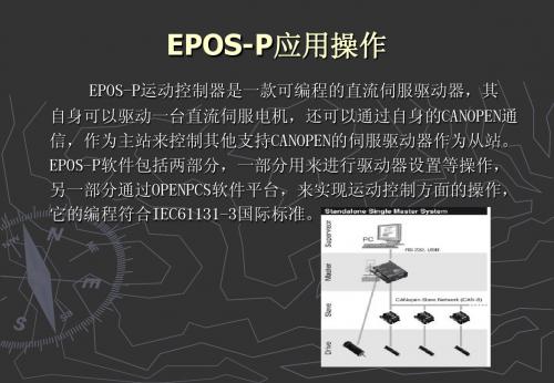
EPOS-P应用操作
功能块:功能块是带有多个输入/ 功能块:功能块是带有多个输入/输出参数和内部存储单元 的POU。功能块的返回值取决于其内部存储单元的值。功能块内 POU。功能块的返回值取决于其内部存储单元的值。功能块内 可以调用另外的功能块或函数,但不能调用程序。不允许递归 调用。功能块的缩写为FB。其内部变量是保存的。调用功能块 调用。功能块的缩写为FB。其内部变量是保存的。调用功能块 时要为功能块指定实例,(实例在声明部分声明,声明数据类 型为该功能块名),这样一个功能块才能被定义一次而使用多 次。 程序: 程序:程序是根据控制器过程的需要,包含了函数和功能 块的一个逻辑组合的POU。程序一定要被关联到任务上。在程序 块的一个逻辑组合的POU。程序一定要被关联到任务上。在程序 内部,可以调用函数和功能块。不允许递归调用。
“POU”用于建立程序、功能块和函数,以及编程方式选择。 “POU”用于建立程序、功能块和函数,以及编程方式选择。 要建立一个新程序,在上面选择编程语言,文件名和存储这个 程序的目录,新建的类型(Program、 程序的目录,新建的类型(Program、Function Block、 Block、 Function)。当新建程序时,点击OK,这时将选择是否把新程 Function)。当新建程序时,点击OK,这时将选择是否把新程 序链接到当前资源,单击“YES”,在当前资源下一个新任务将 序链接到当前资源,单击“YES”,在当前资源下一个新任务将 出现在资源窗格中。也可以手动链接, 出现在资源窗格中。也可以手动链接,如下图所示。
程序,一个IEC程序可以用符合IEC 61131-3规定的编程语 程序,一个IEC程序可以用符合IEC 61131言来编写。典型的IEC程序由许多互连的功能块和/ 言来编写。典型的IEC程序由许多互连的功能块和/或函数组成, 每个功能块之间可相互交换数据。函数与功能块是基本的组成 单元,其内包括一个数据结构和一种算法。 对于只有一个处理器的小型系统,其模型只有一个配置、 一个资源和一个程序,与现在大多数PLC的情况完全相符。对于 一个资源和一个程序,与现在大多数PLC的情况完全相符。对于 有多个处理器的中、大型系统,整个PLC被视作一个配置,每个 有多个处理器的中、大型系统,整个PLC被视作一个配置,每个 处理器都用一个资源来描述,而一个资源则包括一个或多个程 序。对于分散型系统,将包含多个配置,而一个配置又包含多 个处理器,每个处理器用一个资源描述,每个 全局变量:这些变量没有硬件地址,比如用于中间结果。 直接全局变量:这些变量有直接硬件地址和IO声明,他们 直接全局变量:这些变量有直接硬件地址和IO声明,他们 代表硬件接口。 变量声明也可以在“程序编辑窗格”上面部分的声明变量 的窗口中来进行。 格式为:变量名 AT 地址:类型:=初始值;*注释* 地址:类型:=初始值;*注释* 其变量种类分为Local、Global、External、Input、 其变量种类分为Local、Global、External、Input、 Output、In_Out。 Output、In_Out。 常用数据类型: BOOL 0(FALSE),1(TRUE) SINT 短整型 8位 INT 整形 16位 DINT 双整形 32位 UINT 无符号整形 16位 UDINT 无符号双整形 32位 REAL 实型 32位
进口单证操作规范1006

进口单证操作规范:一、发车前Ⅰ.品名确认:a)供名硕部分的料件(新宁保税、苏高加工和苏高物流)的品名、编码确认,可由VMMS系统导出有料号栏的EXCEL表格,以邮件方式发给ASUS关务,ASUS关务将对应的品名、编码邮件回复,根据EXCEL表内容维护VMMS系统。
当ASUS关务无法回复的部分:若近期(2-3个月)走过,可按近期系统里的品名和编码维护系统;若近期没有走过就可能有两种情况 1)系统料号和文件料号不一致,及时通知深圳BDC要求通知对应的CS进行确认,按照正确料号维护系统。
2)新料号部分要求驻厂和CS配合确认具体为: 苏高加工路线找驻厂苏蕾协助苏高物流路线找驻厂许艳协助新宁保税由苏高新操作找对应物控提供,如果驻厂和苏高新操作均无对应物控联系方式时要求BDC通知对应CS要求供应商提供物控联络窗口以便确认品名。
b)其他客户(ASUS以外的)的品名、编码确认最近两个月系统有历史记录的,按历史记录维护系统,同时将资料发给收货人确认;对新料号部分以邮件方式,将文件(INV、P/L)发给客户,客户回复邮件,根据客户回复的品名、编码进行维护VMMS系统。
Ⅱ.单证确认:a)发往苏高加工和苏高物流的货物排车前由驻厂负责确认。
b)苏高新(新宁)货物在排车前,深圳BDC每天下午15:00左右会邮件发出“苏高新新宁发货明细”,单证负责人在收到信息后,分别将每一票与对应的物控确认:1) 告之预计到仓时间,让物控回复急缓信息。
2)查看EPO文件正常情况EPO文件由供应商提供的核对好送货地址,待货到我司香港仓库即可发车,但物控有特殊要求的除外; EPO文件由物控提供的部分拿到物控提供的EPO文件后要核对EPO文件与供应商提供的文件是否一致包括:送货地址、数量、料号和金额等。
以上信息确认好后全部邮件回复深圳BDC,同时电话确认。
二、提前报关与发车当天Ⅰ.提前报关部分发车前一天,接收预申报资料(INV、P/L、车牌、口岸、柜号、白卡编号),整理、核对后,传递给收货人和收货人对应的报关行,进行预申报。
EPIP30 系列智能控制器 说明书
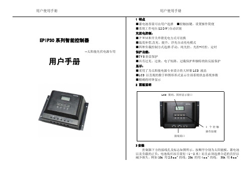
LCD数码、图形显示窗口接线端口太阳标志,表示白天和晚上光控启动点的状态;)择任一种方式;)蓄电池符号,内部条状图形表示充放电状态及当前容量百分比如果系统处于放电状态,则蓄电池的方式显示蓄电池处于放电状态;保险负载状态标志蓄电池状态充电控制方式参数及参数单位显示区负载控制方式标志闪烁,充电恢复后停止闪烁;直流输出符号;负载图标,表示负载状态及故障状态;常显,当允许输出为“开”状态时,显示负载状态;过载时,负载符号K4负载和闪电符号闪烁次短路保护动作,需用户检查负载线路,参数单位:LCD池容量,符号显示,充电符号“”闪烁,表示当前可以修改充电控制方号及充电符号“”闪烁时,按一下显示,恢复原控制方式,并返回到参量选择状态;在“SET”符号显示及太阳符号“符号闪烁,表示现在可以确认设置光启动电压,再按一下当出现太阳图形在天黑自动的启动负载输出,白天自动关闭输出。
太阳,表示光控+延时,控制器会自动检测光强弱,在天黑自动的启动负载输出,同时根据所选择的工作时长自动关闭负时钟无图形显示,表示手动控制;3.6时间调整操作:包括实时时间、延时时间和定时开关时间;●在负载控制为手动、光控模式下,只显示调整实时时间。
●在光控+延时模式下,可以调整实时时间和延时关闭小时数。
●定时模式下可以调整实时时间和定时开、关对应的小时、分钟数据,用户首次使用,默认的控制时间数据均为0,所以在首次连接使用时要设置相应的时间,之后,控制器按照最后一次的设置参数工作;1)在显示需要调整的时间时,按一下K3,“SET”符号及右下角的H:M 符号中的H闪烁,表示可以修改小时数据;2)通过K1/K2在0~23内调整数据;3)再按一下K3,保存小时数据并切换到修改分钟数据--“SET”符号及右下角的H:M符号中的M闪烁;4)通过K1/K2在0~59间调整数据;5)再次按K3保存修改数据,返回到选择状态—显示“SET”不闪烁;6)如果不保存更改,则按K4,返回到选择状态—显示“SET”不闪烁;3.7光控测试在浏览状态下,同时按下K1和K2键,放开后右侧太阳闪烁,控制器进入测试模式:光电池输入端加低于5V的电压,控制器开通输出光电池输入端加高于7V的电压,控制器关断输出如果符合上述现象,说明控制器光控功能正常,按K4键退出测试模式,返回浏览状态5安全及保护本控制器具有过压、过流、短路、反接等全保护功能,具有TVS防雷保护,并且过压、过流、短路保护在LCD上具有告警指示。
EPIP603 型智能控制器

EPIP603型智能控制器─太阳能光伏电源用用户手册1特点■PWM脉宽调制充电■直充、提升、浮充自动充电模式■根据实际充、放电率智能修正控制参数的准确控制(SOC )■发光二极管系统工作状态指示■温度补偿,采用机内、外高精度数字温度传感器测温■过载、短路保护■精确的电池电量测量显示■实时时钟及显示■LCD中英文菜单显示■用户可设定系统工作参数■RS232计算机通讯接口■历史数据记录和下载2面板说明3操作及显示说明①按键说明:面板上从左到右的4个按键依次说明1)确认键(SET ):确认当前选择或者修改;2)取消键(CANCEL ):取消当前选择或者修改,并返回上级菜单;3)选择键(SELECT):用于选择要修改的内容或选择菜单选项;4)开关键/修改键(POWER/MODIFY):用于手动控制负载输出;发生过载、短路保护时按下可以复位这些故障;在数值修改状态下,用于单方向增修改数值;②菜单操作过程如下:1)上电时,液晶显示图1;接线端子排通讯口机外高精度数字温度传感器1A30V 器输出图12)正常工作后,显示“运行参数”(以下都以12V 系统为例)的前两项,如图2所示。
共有9项运行参数:电池电压、电池电量、充电电流、负载电流、充电电压、充电电量、机内温度、电池温度以及系统时间等,可以通过选择键进行查询,每次按下选择键,显示将按照图2、图3、图4、图5、图6、图2的顺序循环显示。
3)在显示“运行参数”时,按下取消键,将显示图7所示“主菜单”,并选中第一项。
注意当前屏幕只显示前两条菜单选项。
此时通过选择键可以进行菜单选项的选择。
每一次按下选择键,选中的光标将向下移动一项,当选择最后一项时按下选择键将选中第一项。
4)若选择的是第一项“1.运行参数查阅”,系统将显示“运行参数”;见第2)项描述; 若选中的是第二项“2.设定参数查阅”,系统将显示系统可以设定的一些参数,通过选择键用户可以查询图8、图9、图10所示内容;若选择的是第三项“3.设定参数”,系统首先提示输入密码,如图11所示,默认密码是1234;正确“输入密码”(见第5)项描述)进入“设置菜单”后,用户可以设置图12所示的8项设定参数(见第6)项描述),设置完所有的参数后,按取消键返回主菜单,或者等待10秒钟,系统自动退出“设置菜单”,显示“运行参数”。
ERP物控操作流程详解
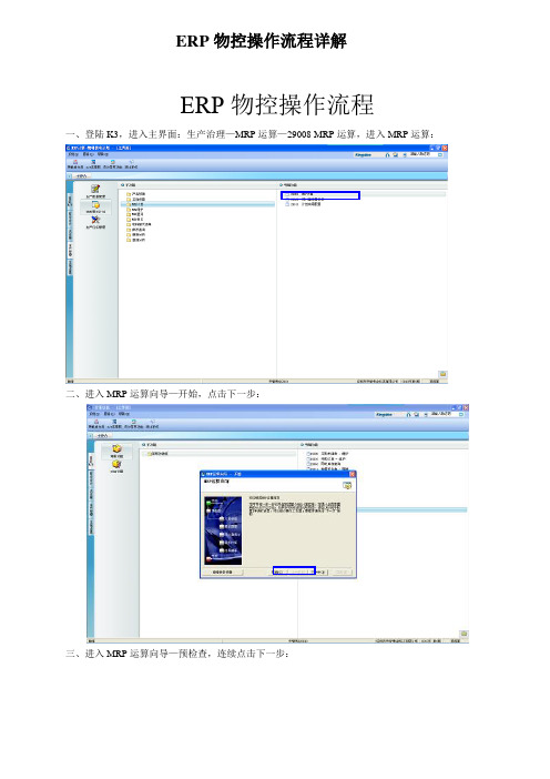
ERP物控操作流程详解ERP物控操作流程一、登陆K3,进入主界面:生产治理—MRP运算—29008 MRP运算,进入MRP运算:二、进入MRP运算向导—开始,点击下一步:三、进入MRP运算向导—预检查,连续点击下一步:四、进入MRP运算向导—方案参数,连续点击下一步:五、进入MRP运算向导—需求猎取,点击选择:六、进入销售订单序时薄,选择需要运算的订单及物料,选择后按回车键或者点‘返回’:七、进入MRP运算向导—需求猎取,连续点击下一步:八、进入MRP运算向导—估量量展现,连续点击下一步:九、进入MRP运算向导—需求运算,运算完后连续点击下一步:十、进入MRP运算向导—查看结果,核对完数据后连续点击下一步:核对数据十一、进入MRP运算向导—完成,运算完成:十二、MRP运算向导—完成,运算完成后,点击生产治理—MRP爱护—29012 MRP打算订单—爱护,点击确认:十三、进入MRP打算订单,选择单据审核然后进行投放,打算订单投放完成:审核单据点击是,查看投放结果,完成打算订单投放十四、点击供应链—采购申请—采购申请单—爱护—确定,审核采购申请单,完成打算物料需求,产生采购订单:审核单据,Y表示已审核采购流程采购订单的下达方式一1〕进入〝供应链〞———>>选择子功能〝采购订单〞———>>选择明细功能〝采购订单-新增〞2〕进入〝采购订单〞———>>从〝源单类型〞———>>选择〝采购申请单〞———>>点击〝选单号〞进入3〕按需求选择4〕依照表单增写:供应商/备品数量/单价/交货时刻/业务员等信息———>>确认———>>储存采购订单的下达方式二1〕进入〝供应链〞———>>选择子功能〝采购订单〞———>>选择明细功能〝采购订单-爱护〞2〕弹出〝条件过滤〞窗口———>>点击〝确认〞进入4〕选择物料———>>点击下推———>>生成采购订单采购订单爱护1〕进入〝供应链〞———>>选择子功能〝采购订单〞———>>选择明细功能〝采购订单-爱护〞2〕弹出〝条件过滤〞窗口———>>点击〝确认〞进入3〕弹出所有过滤明细——>>选择自己要进行更正明细———>>点击右键可进行修改、删除等等〔备注:要先反审核〕4〕修改完成后———>>确认———>>储存采购发票的结算1〕进入〝供应链〞———>>选择子功能〝采购发票〝—>>选择明细功能〝采购发票新增〞2〕进入〝购货发票〞———>>在右上角选择〝购货发票一般〞———>> 点击〝选单号〞进入备注:正常进货选择蓝字/不良品退货选择红字3〕按需求选择4〕确认数量、单价、部门、业务员———>>增写发票号———>>确认———>>储存采购发票的爱护1)进入〝供应链〞———>>选择子功能〝采购发票〞—>>选择明细功能〝采购发票爱护〞2〕弹出〝条件过滤〞窗口———>>点击〝确认〞进入3〕弹出所有过滤明细——>>选择自己要进行更正明细———>>点击右键可进行修改、删除等等〔备注:要先反审核〕商务销售K3流程商务流程图:1,销售报价每个机型第一把每个客户端报价单做入系统,以后的销售订单可依照销售报价直截了当生成销售订单如图1-1〕,先在销售治理选择销售报价打开销售报价单-新增进入销售报价单界面图1-1〕进入销售报价单界面后,如图2〕。
EP系列Pro-Bloc安装和操作手册说明书
IPDE-IOM-EP-SERIES-PROBLOCEffective: July 2018Effective: April 2021Installation and Operation Manual EP Series Pro-B loc®Parker HannifinParker Hannifin (IPDE)Riverside Road, Barnstaple, Devon, EX31 1NP United KingdomTelephone: (01271) 313131E-mail:*****************************.comIDENTIFICATION OF HAZARDSNEVER adjust valves under pressure.NEVER slacken or remove any valve parts under pressure.NEVER use any mechanical aids i.e. wrenches, extensions to operate handles.NEVER carry ball valves by the handle.NEVER obscure valve body marking.NEVER remove end connectors.NEVER use valves outside of rated operating conditions.INSTALLATIONWear suitable PPE before installation and follow appropriate site safety procedures.Before installation, ensure that all valves are in the closed position.Parker Pro-B loc® uses standard flange connections. For connection, please refer tothe appropriate installation standard for the flange specification in question.For non-flange end connection:•NPT: Use standard practice for NPT taper threads. Use an appropriate thread tape or sealant to prevent galling.•A-lok/CPI: See separate instruction sheet supplied with A-lok products.HANDLING AND STORAGEHandlingLarger sized Pro-B locs may be heavy. Ensure that local manual handling requirements are followed. Do not lift or carry by the operating handles, as this may cause damage.StorageThere is no specified shelf-life.Boxed products should be stored in a covered area, preferably indoors, and away from excessive moisture, heat, or airborne contaminants.The use of desiccant or corrosion inhibitors is not required during normal storage periods.OPERATIONBall Valve:To close: Operate the handle until it is at 90° from the valve body centreline.To open: Operate the handle until it is in line with the centreline of the body and reaches the stop pin. Movement is limited to 90° (except for vent ball valves) by a mechanical stop pin.Ball valves should always be fully open or fully closed. Do not leave in a mid-position.Three-way vent ball valves (red handle) have no firm centre-off position and are positioned visually. Needle Valve or Outside Screw and Yoke (vent):To close: Rotate handle clockwise until a stop is felt.To open: Fully rotate the handle anti-clockwise until a stop is felt.There are approximately three rotations between fully open and fully closed.Do not force rotation past the stop, as damage may occur. Maximum torque is 6NmFor anti-tamper designs only use the correct key for Parker manifolds.ISOLATE VALVE OPERATING POSITIONSISOLATE BALL VALVE IN CLOSED POSITIONISOLATE BALL VALVE IN OPEN POSITION.BALL VENT VALVE OPERATING POSITIONSVENT BALL VALVE IN CLOSED POSITIONVENT BALL VALVE IN OPEN POSITION.OPERATING SEQUENCEThese valves are primarily used for double isolation of an instrument, be that a gauge or a transmitter. The primary and secondary valves are in the open position during normal operating conditions allowing the process pressure to enter the gauge or transmitter to perform its function to give a pressure reading. The words Primary and Secondary are printed on the blue vinyl sleeves to aid identification.When the gauge or transmitter need removing for calibration in a workshop, the primary valve is closed to block the pressure, the secondary valve remains open and vent valve is opened to release the pressure within the instrument.The secondary and vent are then closed (the primary valves is already closed) and the instrument safely removed.The double block gives two isolations to prevent process escape while the instrument is removed. Once the instrument is calibrated or replaced with a new one it can be fitted back on top of the valve outlet and the primary and secondary valves opened again to allow pressure measurement to continue.It is possible to calibrate a pressure transmitter without removing it; this is in situation calibration commonly called “in-situ” calibration. To do this you follow the above procedure to vent the valve. Then a known pressure is pumped into the open vent, a handheld device is then connected to the back of the transmitter with electrical leads after removing the cover. If the known pressure from the pump agrees with the electrical reading from the transmitter it is in calibration and the measuring equipment removed, then the valves are returned to their operating positions.If however the readings do not agree, the measuring device has the ability to electronically change the reading to make it agree with the known pressure, this is done by turning a k nob clockwise or anticlockwise to change the reading of the transmitter up or down to suit, this is the “in-situ” calibration completed and the valves are again returned to their operating positions.Vent plug: The valve is shipped with a vent plug; loose or installed, as per the client’s requirements. While venting the valve this plug must be removed. The plug can be replaced for safety reasons or to prevent ingress of the environment. That is the operator’s decision and should be in their operating procedures. Parker are not responsible for this decision. It is suggested that PTFE tape or sealant is used to prevent galling of the threads.BALL VALVE HANDLE REMOVALBall Valve handle removal/reinstallationThe ball handle may be removed without under loading the packing. To remove the handle •Unscrew the top nut (Dome/handle locking nut)•Handle may be removed.To re-install the handle for valve operation:•Ensure shaft and nut threads are free from contaminants (including any used thread locker)•Replace handle•Apply Bondloc B272 or equivalent to nut threads ensuring good coverage.•Torque nut as follows:Pro-B loc Size:Top Nut Torque (Nm)10mm (EPBY), 15mm (EPBW), 20mm (EPBV) 23 Nm25mm (EPBV) 31 NmWARNING: Ensure handle is correctly installed before operation of valveTOP NUTSTOP PINHANDLESHAFTEEMUA Ball valveMAINTENANCEParker Pro-B locs are not user-serviceable, except for gland adjustment of the vent needle valve. Gland adjustment becomes necessary when the valve is visibly leaking through the spindle just below the operating handle, or prior to operation when no torque or resistance is evident when operating the valve handle. Adjustment to the gland can be carried out to prevent leakage. Replacement bonnets are available.H-series Needle Valve Gland Adjustment.CAUTION: Adjustment of the gland must be carried out at zero pressure1.Fully close the valve by turning the handle in a clockwise direction to stop lightly on seat(max. 2 Nm).2.Open the valve one full turn by rotating the handle in a counter-clockwise direction.3.Loosen gland lock nut.4.Tighten gland nut to 11 Nm5.Re-tighten gland lock nut to 25 NmH-Series Bonnet HANDLEGLAND NUT GLAND LOCKNUTPage 10 of 10 ECO-0364767 Rev: - Installation and Operation ManualEP Series Pro -B loc ®IPDE-IOM-EP-SERIES-PROBLOC Outside Screw and Yoke Valve Gland Adjustment. CAUTION: Adjustment of the gland must be carried out at zero pressure 1.Fully close the valve by turning the handle in a clockwise direction to stop lightly on seat (max. 2 Nm).2.Open the valve one full turn by rotating the handle in a counter-clockwise direction.3.The two bridge-nuts on either side of the spindle must be tightened evenly, keeping the bridge parallel to the body, to a torque of 5Nm.FURTHER INFORMATIONCv values:•10mm bore (PBY): 6.4•15mm bore (PBX): 15•20mm bore (PBW): 31•25mm bore (PBV): 39Needle valve sea t:•6mmCross hole drillings:•5mm HANDLEOutside Screw and Yoke (OS&Y) BonnetBRIDGE NUT(ONE EACHSIDE) BRIDGE。
MeePo用户使用手册

人红细胞生成素EPO说明书
人红细胞生成素(EPO)酶联免疫分析(ELISA )本试剂仅供研究使用目的:本试剂盒用于测定人血清,血浆及相关试剂盒使用说明书液体样本中红细胞生成素(EPO的含量实验原理:本试剂盒应用双抗体夹心法测定标本中人红细胞生成素(EPO)水平。
用纯化的红细胞生成素(EPO)抗体包被微孔板,制成固相抗体,往包被单抗的微孔中依次加入红细胞生成素(EPO),再与HRP标记的红细胞生成素(EPO)抗体结合,形成抗体-抗原-酶标抗体复合物,经过彻底洗涤后加底物TMB显色。
TMB在HRP酶的催化下转化成蓝色,并在酸的作用下转化成最终的黄色。
颜色的深浅和样品中的红细胞生成素(EPO)呈正相关。
用酶标仪在450nm波长下测定吸光度(0D值),通过标准曲线计算样品中人红细胞生成素(EPO)浓度。
试剂盒组成:样本处理及要求:1•血清:室温血液自然凝固10-20分钟,离心20分钟左右(2000-3000转份)。
仔细收集上清,保存过程中如出现沉淀,应再次离心。
2. 血浆:应根据标本的要求选择EDTA或柠檬酸钠作为抗凝剂,混合10-20分钟后,离心20分钟左右(2000-3000转/分)。
仔细收集上清,保存过程中如有沉淀形成,应该再次离心。
3. 尿液:用无菌管收集,离心20分钟左右(2000-3000转份)。
仔细收集上清,保存过程中如有沉淀形成,应再次离心。
胸腹水、脑脊液参照实行。
4. 细胞培养上清:检测分泌性的成份时,用无菌管收集。
离心20分钟左右(2000-3000转/分)。
仔细收集上清。
检测细胞内的成份时,用PBS(PH7.2-7.4 )稀释细胞悬液,细胞浓度达到100万/ml左右。
通过反复冻融,以使细胞破坏并放出细胞内成份。
离心20分钟左右(2000-3000 转/分)。
仔细收集上清。
保存过程中如有沉淀形成,应再次离心。
5. 组织标本:切割标本后,称取重量。
加入一定量的PBS,PH7.4 。
用液氮迅速冷冻保存备用。
标本融化后仍然保持2-8C的温度。
EPOTEK产品使用指南-通泰

EPOTEK产品使用指南—————————————————————————————1 使用范围1.1本产品使用指南适用于上海通泰化学有限公司代理的EPOTEK产品包括双组分、单组分、预混产品(针筒装)的运输,储存,解冻,混合以及其他注意事项。
2 接收• 在收据的上方,检查特定产品的TDS 。
• 阅读并参照MSDS确认EPO-TEK产品正确的化工卫生说明(安全预防措施)。
• 用干冰运输的产品应该立刻转移到-40˚C 冷藏设备中。
3 单组份产品3.1储存3.1.1 单组份的产品典型的是储藏温度通常为:1. 冷藏储存产品2-5℃2. 冷冻储存产品-40℃3. UV产品具体参见TDS, 未特别指明冷藏存储的产品,均在常温下避光存储。
• 注:1)请参见产品TDS。
对于紫外胶还另需避光存放。
2)新产品按原厂确认的信息执行在存储在冰箱中时,建议与其他产品隔离存放。
推荐方法如:使用自封袋,密封盒,或者封口膜。
主要是为了防止其他带有挥发性的产品对本产品造成无法预估影响。
注:在未达到周围环境温度之前打开容器,空气中水汽会进入胶体干扰固化,影响产品质量。
3.2 产品的解冻要求:3.2.1冷藏或冷冻产品的解冻:放置在常温(如有条件,建议为室温(23˚C-27˚C), 湿度(40-60% RH))的环境下,放置到与周围温度一致即可。
产品从冰箱或泡沫箱中取出时,建议先用毛巾或无尘纸裹起来回温。
(冷冻产品解冻可选建议:从-40℃的冷冻设备中先转移到0℃设备中解冻30min左右,在放入常温下进行完全解冻)回温时间: 建议30min~1小时比较合适,具体以与环境条件一致为准***注:在未解冻完成之前,请勿打开。
A,未完全解冻的产品:胶水解冻不完全,会影响产品施胶;胶水解冻不完全还可能造成水汽侵入,影响胶体品质B,产品再次冷冻或冷藏处理:如解冻后只取部分胶水使用,请取出所需要使用的胶水后,剩余部分立即封盖。
较长时间不使用,请放回冷藏或冷冻设备中。
EPR300电动机保护控制器说明书
Ever Power
EPR300 电动机保护控制器
技术说明书 使用说明书 (V1.00)
SHANGHAI EVER POWER AUTOMATION CO.,LTD.
上海久创自动化设备有限公司
EPR300 电动机保护控制器
Ever Poห้องสมุดไป่ตู้er
声明
感谢您购买了上海久创电气自动化设备有限公司的数字式保护装置。 EPR300 系列电动机保护控制器是我公司吸取国内外先进技术, 面向 660V 以 下供电系统推出的保护、监控功能一体化装置。可以替代传统的继电器和仪表 监测,既可以在开关柜上分散安装,也可以集中组屏安装。 装置采用完全汉化技术,人机界面友好,使您免除找说明书操作的麻烦。 EPR300 电动机保护控制器具有以下优点: 基于分布式设计思想,以一个马达为控制对象。各装置之间通过网络和主 站连接,任何一个装置故障不会影响其他装置的正常工作,这个系统可靠性很 高。 装置结构简洁,内部强弱电完全隔离,使装置的抗电磁干扰能力和抗震能 力大大提高,满足现场运行的恶劣环境。 装置采用分体式结构,主控制体可以通过导轨安装在屏体的内部,面板显 示安装在屏体的前部,满足各种现场安装需求。 全汉化液晶显示,人机界面友好,键盘操作方便,遥测、遥信、保护动作 报告、告警信息等都能在液晶上显示,是调试、运行、维护方便。
翠欧控制卡入门手册-MC206X-学习..
目的 (2)原则 (2)内容 (2)1 用途 (2)1.1 应用领域 (2)1.2 应用实例 (3)2 运动控制系统构架 (3)2.1 组成 (3)2.2 各部分功能 (4)3 配线 (6)3.1 MC206X介绍 (6)3.2 供电 (9)3.3 控制器、驱动器配线 (9)3.4 孔制器、上位机连接 (12)4 软件编程 (12)4.1 支持软件使用 (12)4.2 简单运动指令举例 (27)4.3 简单运动控制程序举例 (34)目的通过阅读本手册,让刚刚接触TRIO运动控制器的客户可以从用途、系统构架、TRIO 在系统中的作用以及软、硬件有一个初步的了解。
其中最主要的是,通过本手册一定要让用户能够自己搭建一个简单的控制系统,能用Motion Perfet与控制器、电机连接起来,对电机进行一些简单的操作。
为用户未来使用TRIO运动控制器开发项目打下基础。
原则简单、实用、图文并茂。
内容1 用途1.1 应用领域TRIO运动控制器主要应用在工业控制领域,可以对伺服,步进,变频器等进行控制。
其特点是指令简单,完成复杂的多轴协调运动,只需几条简单的指令就可以完成。
1.2 应用实例2 运动控制系统构架2.1 组成2.1.1 运动控制系统概念运动控制是指在一定的环境中,根据给定的条件,将预定的控制方案、规划指令转变成期望的机械运动。
实现对被控目标机械部件精确的位置控制、速度控制、加速度控制、转矩或力的控制,以及这些控制的综合控制。
当今的运动控制,由于环境条件的复杂,使得控制方案,数据也显得越来越复杂,这样,实际中要想完成预定的动作,实现准确的运动控制,更多的依靠大型的运动控制系统。
运动控制系统包括处理运动算法和信号的控制器、增强信号,可供应运动控制器提供运动输出的放大器、执行机构、反馈系统(传感器/变送器),可基于输出和输入的比较值,调节过程变量。
有的系统还包括操作员界面或主机终端前端处理设备。
2.1.2 运动控制系统框图2.2 各部分功能人机交互:一般由上位机或触摸屏完成人机交互功能。
《普洛斯物业管理操作手册》 V4

普洛斯物业管理操作手册(Version 4)2014年10月目录(欢迎对本手册及附件提出任何完善性建议并请发送邮件至:yizhai@glprop。
com)第一章总则 (7)1.1 手册制定目的 (7)1.2 手册适用范围 (7)1.3 手册修订 (7)1.4 物业经理主要职责 (7)第二章供应商管理 (8)2.1 物业供应商的类别 (8)2.2 物业管理服务供应商的选择 (8)2。
2。
1 物业管理服务供应商选择的原则 (8)2.2.2 可以引入新物业管理服务供应商的项目 (8)2.2。
3 在管项目物业管理服务协议的续签条件 (8)2.2.4 新项目物业供应商的选择 (9)2.2。
4。
1 职责 (9)2。
2。
4。
2 物业管理服务供应商的选择和招投标 (9)2。
3 物业工程及零星修理供应商选择的特别要求 (14)2。
4 服务过程的监督和管理 (15)第三章客户服务 (16)3.1 客户服务 (16)3.1。
1 迁入 (16)3.1.1。
1 迁入前的准备工作 (16)3。
1。
1。
2 物业部与租户移交 (17)3。
1。
2 续租 (18)3.1.2.1 客户的续租 (18)3。
1.2.2 一般客户的续租(略) (18)3。
1.3 终止租赁关系(迁出) (18)3。
1.4 客户标识 (19)3.1。
4。
1 许可与禁止 (19)3.1.4。
2 程序 (21)3.1。
5 用电增容 (22)3。
1。
6 二次装修 (22)3.1。
6。
4 二次装修申请所需文件 (22)3.1。
6.5 二次装修手续办理及日常监督 (23)3.1.6.6 现场的消防防火 (23)3。
1。
6。
7 垃圾/废料清运 (24)3.1.6.8 文明施工保证金 (24)3.1.6。
9 墙面与管线 (25)3.1.6。
10 后加设备/物件 (25)3。
1.6.11更改/还原 (26)3.1.7 报修服务 (27)3.1。
7.1 对客户报修处理的程序要求 (27)3。
- 1、下载文档前请自行甄别文档内容的完整性,平台不提供额外的编辑、内容补充、找答案等附加服务。
- 2、"仅部分预览"的文档,不可在线预览部分如存在完整性等问题,可反馈申请退款(可完整预览的文档不适用该条件!)。
- 3、如文档侵犯您的权益,请联系客服反馈,我们会尽快为您处理(人工客服工作时间:9:00-18:30)。
關務確認窗口:
Emily2 Liu(柳至菡_PSH)
May He(何金梅_PSH) Lisa6 Chen(陳莉莉_PSH)
12
•QP確認
路徑:ePO > Material > QP Confirm
•供應商依據我司收貨入庫的記錄,向海關QP系統發送QP出貨信息,得到QP出貨單編號 •并將該編號維護在以下界面對應之收貨入庫記錄.Save完資料后, 我司進口會以此向海關QP發 送收貨信息 •供應商必須在出貨的72小時內發送QP出貨信息
欄位名稱 GR Date From GR Date To BU Ship NO PO NO Received NO Part Number ship Mode Query Download 解釋 收貨日期從…… 收貨日期到…… 庫別 出貨單號 訂單單號 收貨單號 料號 請選擇走貨模式 (結轉&當地采購) 查詢 下載
30
• • •
看不到新庫別下的訂單
Step1:點擊如下帶下劃線的User ID(點擊廠商自己實際用的User ID)進入下 一界面 Step2:Select Groups欄位選好庫別,例如SAPSH-2A71(2A71) Step3:點擊SAVE,保存即可
31
看不到新庫別下的訂單
32
• • •
路徑:ePO > Order > Purchase Order List
欄位說明
Need Approve New Send Negotiate Confirm Closed Cancel
說明
開立中,簽核中 新發送 協議中 已確認 已結案 已取消
欄位說明
Status Qty Shipped Qty Received Qty Return Qty
• 物控如何撈到自己結轉廠商的對帳單?
• 物控如何設置和取消廠商Reel ID卡關權限?
• 新舊Vendor code Mapping
18
登陸EPO的員工界面,員工要 如何登陸?
19
路徑:ePO > Order > PO Change
物控和MRO采購如何做采購變更?
20
物控如何查詢訂單以及進入廠商界面?
關務確認窗口: May He(何金梅_PSH) Lisa6 Chen(陳莉莉_PSH) Jane2 Wang(王志慧_PSH)
10
• 維護料件是結轉還是非結轉
• 路徑:ePO > Material > Customs Material Maintenance 點擊Customs Property Maintenance
說明
顯示訂單狀態 采購量 出貨量 收貨量 退貨量 21
路徑: ePO > Order > ERP PO Query
物控如何手動拋單?
22
物控如何查直出的廠商有沒有維護EPO出 貨單?
路徑:ePO > Shipment > Vendor Incoming Report (MC)
23
路徑:ePO > Shipment > Ship leaddays Setup
EPO操作手冊
1
目錄 EPO平臺介紹
EPO廠商界面 EPO物控界面
异常Case Study
2
EPO平臺介紹
• 提供e化平台,即時資訊交換
– 將採購資訊透過EPO平台讓供應商即時查看,並可讓供應商反饋出貨 訊息。
• 電子化文件管理
– 透過EPO平台將PO單據電子化,並提供出貨單/Invoice/Packing List 等單據標準化格式。
16
EPO物控界面
17
•
EPO物控界面 登陸EPO的員工界面,員工要如何登陸?
• 物控和MRO采購如何做采購變更?
• 物控如何查詢訂單以及進入廠商界面?
• • • 物控如何手動拋單? 物控如何查直出的廠商有沒有維護EPO出貨單? 物控如何by PO修改的前置天數?
• 物控如何by廠商修改的前置天數?
确认预结转手册
物管
出 货
维护预结转手册
維護出貨單
收 货
收貨入庫
QP出货資料確認
QP收货資料確認
对 帐
結轉對帳單 8
• 海关监管编码
• 路徑:ePO > Administrator > Local Transfer Vendor Setup
SAPSH-122A
常见问题:
昌碩
結轉廠商做出貨單的時候, 解決方法:維護海關編碼 ship mode下拉菜單, 沒有結轉的選項.
• 做為物控/採購與供應商間溝通的橋樑
– 廠商與物控/採購透過平台進行出貨交期溝通,以及收貨對帳與付款資 訊查看。
• 強化供應鍊管理
– 透過EPO來強化供應商庫存管理,並洐生與擴展相關供應商管理功能 與報表資訊共享。
3
EPO廠商界面
4
入料模式
•OverSea Shipment
– 指从机场入料,有HAWB & MAWB的资料;
物控如何by PO修改的前置天數?
24
路徑:ePO > Shipment > Vender Profile
物控如何by廠商修改的前置天數?
25
物控如何撈到自己結轉廠商的對帳單?
路徑: ePO > Payment > Account Received Report (Buyer)
26
路徑: ePO > Administrator > Vendor Constraint Management
文字
1.Forwarder若为指定货代,则不许填写others;
1.监管区入料以PO形式備貨的都选用Non-VMI 的方式作业; 6
出货单(二)
結轉 當地採購
文字
文字
1.要維護海關監管編碼
2.要維護預結轉資料
1.人民幣的ship mode請選:當地采購 7
结转入料流程 供应商
维护海关监管编码
进口
End
Thanks
38
9
•維護預結轉資料
•路徑:ePO > Material > Customs Material Maintenance 常见问题: •供應商維護預結轉資料, 解決方法:維護預結轉資料 結轉廠商做出貨單的時候, 待關務確認是[Y]的狀態才可以做出貨單 Customs NO./Item 關務確認是[N]的狀態:說明廠商維護錯誤,系統將會發mail通知廠商 沒有下拉資料.
•出货时,供应商需要选择对应的预结转编号
–供应商应在手册有效期前45天开始做手册的更新; –供应商如仍沿用即将到期的手册(手册有效期前30 15 天),则对应的出货单需要进口确认后方可打印出
•結轉對帳單
•路徑:ePO > Payment > Account Received Report
查詢欄位介紹:
物控如何設置取消廠商Reel ID卡關權限?
27
新舊Vendor code Mapping
路徑: ePO > Administrator > Vendor Code Mapping
28
异常Case Study
29
• • • •
忘記密碼
step1:供應商用新vendor code登陸EPO,不清楚密碼,請點擊忘記密碼 step2:把新Vendor code輸入公司代碼和使用者代碼欄位 step3:點擊GO step4:系統將會把密碼發送至指定的郵箱內,點確定即可
ERP写入错误Alert Mail介绍
• 同时EPO会mail通知物控错误原因
错误提示
35
订单处理中
• 错误提示: Document 0100009136 already being processed Inbound DN update failed: Purchase order 100009136 is currently being processed • 原因说明:供应商在保存出货单时,物控正在 修改该张订单,所以系统提示如上错误。 • 处理方法:物控应及时退出SAP订单修改界面, 让供应商再重新update一次出货单。 36
問題:如果料件是結轉料件, 廠商不小心打勾,并Save 了,該料變成非結轉了. 處理方法:請供應商重新選 取該料件,再重新按下 Save
11
•查詢出貨單
•路徑:ePO > Shipment > Manage Shipping Notice點擊Shipment Query&Update
•供應商的預結轉手冊在30天范圍之內過期,系統將不允許供應商Download出貨單. •供應商需聯系我司進口人員,確認該張出貨單,方可Download.
•Non-VMI
– 指境内关外,从保税区、物流园、出口加工区等监 管区进料的,则选择Non-VMI的方式,并需要填写 进口申报方式。
申报方式为:逐笔报关,则为先进口报关,再送货入料;
集中申报,则为先送货入料,再进口报
关;
• 结转
– 依照结转方式入料;
5
出货单(一)
OverSea Shipment Non-VMI
DN已经收货
• 错误提示: The DN: 200010687 had already GR, can't be deleted. • 原因说明:供应商所要修改的出货单,我司已 经收货了。 • 处理方法:物控请和供应商确认该张收货资料 是否有错误?并及时和其他部门做协调。
– 结转或是当地采购:先讓物管revise以后,请供应 商再做修改,重新收货。 – 直出或是Non-VMI:则除了物管需要revise以外,37 物控还需要删除对应的外购提单后,供应商才能做