澳大利亚电缆标准号 全
澳洲电气标准
澳洲电气标准
澳大利亚的电气标准由澳大利亚标准协会(Standards Australia)制定和管理。
这些标准用于确保电气设备、系统和安装的安全性、性能和互操作性。
以下是一些澳大利亚电气领域的主要标准:
1.AS/NZS 3000:《澳大利亚/新西兰电气安装规范》(AS/NZS
3000),通常称为电气安装标准,规定了电气设备和系统在澳大
利亚和新西兰的安装要求。
这个标准包括对电线、电缆、开关、
插座、照明、电气板、接地等方面的详细规定。
2.AS/NZS 3008:《澳大利亚/新西兰电气装置- 电线和电缆的
选择、安装和维护》(AS/NZS 3008),规定了电线和电缆的选择、安装和维护的要求。
3.AS/NZS 3017:《澳大利亚/新西兰电气设备- 电气安全与性
能要求》(AS/NZS 3017),规定了电气设备的电气安全和性能要
求。
4.AS/NZS 3760:《澳大利亚/新西兰电器安全检验和测试- 移
动电器检验和测试》(AS/NZS 3760),规定了对移动电器进行安
全检验和测试的程序。
5.AS/NZS 3100:《澳大利亚/新西兰电气设备- 安全要求》
(AS/NZS 3100),规定了电气设备的一般安全要求。
这些标准覆盖了从电气设备设计和生产到安装和维护的各个方面。
澳大利亚的电气专业人士、工程师、设计师和电工在进行相关工作时通常需要遵守这些标准,以确保工程的安全性和符合法规要求。
标准
可能会定期更新,因此建议查阅最新版本的相关文件。
澳大利亚标准电缆材料中英文对照
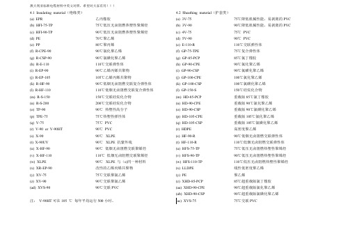
澳大利亚标准电缆材料中英文对照,希望对大家有用!!!4.1 Insulating material(绝缘类) 4.2 Sheathing material(护套类)(a) EPR 乙丙橡胶(a) 3V-75 75℃降低机械性能,易剥离的PVC(b) HFI-75-TP 75℃低压无卤阻燃热塑性聚烯烃(b) 3V-90 90℃降低机械性能,易剥离的PVC(c) HFI-90-TP 90℃低压无卤阻燃热塑性聚烯烃(c) 4V-75 75℃PVC(d) PE 70℃聚乙烯(d) 5V-90 90℃PVC(e) PP 80℃聚丙烯(e) E-110-R 110℃交联弹性体(f) R-CPE-90 90℃氯化聚乙烯(f) GP-75-TPE 75℃复合弹性体(g) R-CSP-90 90℃氯磺化聚乙烯(g) GP-85-PCP 85℃氯丁橡胶(h) R-E-110 110℃交联弹性体(h) GP-90-CPE 90℃氯化聚乙烯(i) R-EP-90 90℃乙烯丙烯共聚物(i) GP-90-CSP 90℃氯磺化聚乙烯(j) R-EP-105 105℃乙烯丙烯共聚物(j) GP-100-CPE 100℃氯化聚乙烯(k) R-HF-90 90℃低烟无卤阻燃交联复合弹性体(k) GP-100-CSP 100℃氯磺化聚乙烯(l) R-HF-110 110℃低烟无卤阻燃交联复合弹性体(l) GP-150-S 150℃硅烷化合物(m) R-S-150 150℃交联硅烷化合物(m) HD-85-PCP 重载版85℃氯丁橡胶(n) R-S-200 200℃交联硅烷化合物(n) HD-90-CPE 重载版90℃氯化聚乙烯(o) TP-90 90℃热塑性高分子(o) HD-90-CSP 重载版90℃氯磺化聚乙烯(p) TPE-75 75℃热塑性弹性体(p) HD-105-CPE 重载版105℃氯化聚乙烯(q) V-75 75℃PVC (q) HD-105-CSP 重载版105℃氯磺化聚乙烯(r) V-90 or V-90HT 90℃PVC (r) HDPE 高密度聚乙烯(s) X-90 90℃XLPE (s) HF-90-R 90℃低烟无卤阻燃交联弹性体(t) X-90UV 90℃XLPE 抗紫外线(t) HF-110-R 110℃低烟无卤阻燃交联弹性体(u) X-HF-90 90℃低烟无卤阻燃交联聚烯烃(u) HFS-75-TP 75℃低压无卤阻燃热塑性聚烯烃(v) X-HF-110 110℃低烟无卤阻燃交联聚烯烃(v) HFS-90-TP 90℃低压无卤阻燃热塑性聚烯烃(w) XLPE 90℃XLPE 与(s)同一种材料(w) HFS-110-TP 110℃低压无卤阻燃热塑性聚烯烃(x) XR-EP-90 改性的乙烯丙烯共聚物(x) LLDPE 线性低密度聚乙烯(y) XV-75 75℃交联聚氯乙烯(y) PE 聚乙烯(z) XV-90 90℃交联聚氯乙烯(z) XHD-85-PCP 85℃超重载版氯丁橡胶(ad) XVS-90 90℃交联PVC (aa) XHD-90-CPE 90℃超重载版氯化聚乙烯(ab) XHD-90-CSP 90℃超重载版氯磺化聚乙烯注:V-90HT可在105 ℃每年平均运行500小时。
电缆国际标准适用国家
美洲:哥伦比亚
非洲:塞浦路斯、马尔他、突尼斯
隶属成员共4个(美洲3个、非洲1个)
美洲:哥斯达黎加(2000年2月)、古巴(1998年1月)、乌拉圭(1996年9月)
非洲:厄立特里亚省
价格=成本+费用+利润
2、F(CIP)货价*(1+保险加成率) *保险费率
计算三:预期利润
利润额=出口成本*利润率
出口报价综合计算
FOB价=出口成本*(1+预期利润率)/外汇汇率
=(实际采购成本+国内总费用)*(1+预期利润率)/外汇汇率
亚洲:中国、印度、印度尼西亚、伊朗、以色列、日本、韩国、马来西亚、巴基斯坦、菲律宾、沙特阿拉伯、新加坡、泰国、土耳其
美洲:阿根廷、加拿大、墨西哥、美国、巴西(2000/12/1重新加入)。
非洲:埃及、南非
澳洲:澳大利亚、新西兰
非正式成员共9个(欧洲5个、美洲1个、非洲3个):
答案:
1、实际购货成本=180*(1+17%-9%)/ (1+17%)=166.15元
2、国内费用=(2000+100+150+600+1800)/500 = 9.3元3、FOB= (实际采购成本+国内总费用)*(1+预期利润率)/外汇汇率
=(166.15+9.3)*(1+6%)/8
信梁公司欲出口500套不锈钢厨具,每套厨具购货成本为180元人民币。经上海至开普敦20英尺集装箱的海洋运费为2200美元,增值税率为17%,退税率为9%。加一成投保一切险,费率为0.8%。该批货物的国内运费共2000元;出口商检费100元;报关费150元;港区港杂费600元;其他业务费用共1800元。如果公司预期利润率为成交金额的6%。请报FOB价。(注:1美元 =8人民币)
全套澳洲有关电缆的试验标准
全套澳洲有关电缆的试验标准
AS/NZS 1660 电缆,导线,导体的试验方法
AS 1660.1 方法1: 导体和金属组件(手头现有此标准) AS 1660.2.1 方法2.1: 绝缘,挤包半导体屏蔽和非金属护套----通用方法(现有第二章)
AS 1660.2.2 方法2.2: 绝缘,挤包半导体屏蔽和非金属护套----人造橡胶,XLPE和XLPVC化合物的特殊试验方法AS 1660.2.3 方法 2.3: 绝缘,挤包半导体屏蔽和非金属护套----PVC和无卤热塑性化合物的特殊试验方法(现有第二章)
AS 1660.2.4 方法2.4: 绝缘,挤包半导体屏蔽和非金属护套----聚乙烯和聚丙烯化合物的特殊试验方法
AS 1660.2.5 方法2.5:绝缘,挤包半导体屏蔽和非金属护套----1kV以上电缆的特殊试验方法(手头现有此标准) AS/NZS 1660.3 方法3: 电试验
AS/NZS 1660.4 方法4: 电缆和软线成品(手头现有此标准)
AS/NZS 1660.5.1 方法5.1: 燃烧试验----成束电缆燃烧试验
AS/NZS 1660.5.2 方法5.2: 燃烧试验----烟密度试验
AS/NZS 1660.5.3 方法5.3: 燃烧试验----从电缆中取出的聚合物材料燃烧时释放出气体卤酸量的测定
AS/NZS 1660.5.4 方法5.4: 燃烧试验----通过测量pH 值和导电性对从电缆中取出的材料在燃烧过程所释放出的气体测定其酸度
AS/NZS 1660.5.5 方法5.5: 燃烧试验----燃烧情况下的线路完整性
AS/NZS 1660.5.6 方法5.6: 燃烧试验----阻燃试验。
AS 5000.3-2003---聚合物绝缘电力电缆第三部分:多芯控制电缆

AS/NZS 5000.3:2003Australian/New Zealand Standard TM澳大利亚/新西兰标准TMElectric cables—Polymeric insulated Part 3: Multicore control cables聚合物绝缘电力电缆第三部分:多芯控制电缆This Joint Australian/New Zealand Standard was prepared by Joint Technical Committee EL-003, Electric Wires and Cables. It was approved on behalf of the Council of Standards Australia on 29 November 2002 and on behalf of the Council of Standards New Zealand on 27 November 2002. It was published on 3 February 2003.本《澳大利亚/新西兰联合标准》由EL-003电线电缆技术联合委员会编制,以澳大利亚标准委员会和新西兰标准委员会的名义分别于2002年11月29日和2002年11月27日获得审批通过,并于2003年2月3日出版。
The following are represented on Committee EL-003:EL-003委员会由下列单位参加:Australasian Railway Association澳大利西亚铁路协会Australian Electrical and Electronic Manufacturers Association澳大利亚电气与电子制造商协会Australian Industry Group澳大利亚工业集团Canterbury Manufacturers Association New Zealand新西兰坎特伯雷制造商协会Department of Defence (Australia)澳大利亚国防部Department of Mineral Resources N.S.W.新南威尔士矿产资源部Electrical Contractors Association of New Zealand新西兰电气承包商协会Electrical Regulatory Authorities Council电气监管机构委员会Electricity Supply Association of Australia澳大利亚供电协会Institution of Engineers Australia澳大利亚工程师协会Ministry of Economic Development (New Zealand)新西兰经济发展部National Electrical and Communications Association国家电气与通信协会Keeping Standards up-to-date关于标准的更新Standards are living documents which reflect progress in science, technology and systems. To maintain their currency, all Standards are periodically reviewed, and new editions are published. Between editions, amendments may be issued. Standards may also be withdrawn. It is important that readers assure themselves they are using a current Standard, which should include any amendments which may have been published since the Standard was purchased.标准是应适时更新的文件体系,反映人们在科学、技术及系统方面取得的进步。
澳标低压电力电缆与国标低压电缆的比较

澳标低压电力电缆与国标低压电缆的比较发布时间:2021-02-26T11:00:00.827Z 来源:《中国电业》2020年29期作者:姚秀艳[导读] 为了解决如何选择出口澳大利亚低压电力电缆原材料等问题,本文通过对比分析澳标与国标主要原材料存在的差异、产品试验的不同。
介绍在生产制造过程中关键工序采取的控制措施。
姚秀艳上海斯麟特种设备工程有限公司摘要:为了解决如何选择出口澳大利亚低压电力电缆原材料等问题,本文通过对比分析澳标与国标主要原材料存在的差异、产品试验的不同。
介绍在生产制造过程中关键工序采取的控制措施。
关键词:AS/NZS标准,低压电缆,原材料,工艺,比较Abstract: In order to solve how to choose the export Australia low-voltage power cable problem such as raw materials, this article through the contrast analysis of Australia and China standard the differences mainly raw materials, product testing. Introduce the key working procedure in the process of manufacturing control measures.Key words: the AS/NZS standards, low voltage cable, raw materials, process, the comparison引言:随着我国改革开放的深入,很多企业出口的机会越来越多。
澳标低压电力电缆执行标准为AS/NZS 5000.1:2005,《Electric cables—Polymeric insulated Part 1:For working voltages up to and including 0.6/1 (1.2) kV》与国标GB/T12706.1《额定电压1kVd (Um=1.2kV)至30kV (40.5kV)挤包绝缘电力电缆,第1部分额定电压1kV的(Um=1.2kV)和3kV的(3.6kV)电缆》结构比较类似,但原材料性能与国标要求存在较大差异,本文就电缆的原材料、产品测试及导体、绝缘、成缆、铠装和护套工序的控制展开说明。
AS 3191中文 软结构电线电缆
澳大利亚/新西兰标准软电线本标准由澳大利亚标准联合会/新西兰标准委员会制定,用来取代标准AS/NZS 3191:2003.本标准的目的是用来特定讲述热塑性塑料,交联聚氯乙烯,交联人造橡胶或者交联聚烯烃绝缘的软电线的结构,尺寸规格和检测。
绝缘的选择是根据软电线的不同类型,用于不同电压,包括250/250 V, 250/440 V和0.6/1 kV而定。
本标准规定的导体截面面积是跟IEC60228标准(绝缘电缆导体)里的一样的。
在IEC标准里出现的相同电线的绝缘和护套的厚度规格被本标准采用。
举例说明,热塑性PVC和交联人造橡胶(elastomer)软电线的绝缘规格分别跟IEC60227(额定电压450/750V及以下的聚氯乙烯绝缘电缆)和IEC60245(额定电压450/750V 及以下橡胶电缆)的标准里的相应电线的绝缘规格一样。
然而,电缆温度额定值并不相同,从而导致绝缘跟护套原料有着不同的性质。
至今还没有一个等同的IEC标准来规定交联PVC或者交联聚烯烃电线的规格。
以下是本标准与2003版标准的不同:(a)玻璃纤维绝缘的软电线已被删除因为此类电线已归类在AS/NZS 3158标准里(b)热塑性人造橡胶绝缘的软电线已被删除(c)所有结构的软电线都附有额定负荷和电压规定(d)规定所有不同类型的软电线的绝缘和护套厚度的表格从结构条文里被移除,并从新整理在4个新表格里。
(e)被推荐的零线颜色从蓝色更改为浅蓝色,与IEC相对应。
(f)一些繁琐累赘的词语从结构要求的条文中被删除(g) 有关标记的条文已被修改(h)交联聚烯烃绝缘原料被增加到本标准术语“规定性的”和“信息性的”在本标准里被用来定义附录的用途。
“规定性的”附录是本标准的主要组成部分,然而“信息性的”附录只是一些信息资料和指导资料。
第一节范围与应用1.1范围 (4)1.2参考文件 (4)1.3定义 (5)1.4电压和负荷规定 (6)第二节结构2.1 导体 (7)2.2 绝缘 (7)2.3 线芯的铺设 (11)2.4 填充物与粘合剂 (11)2.5 屏蔽 (12)2.6 护套 (12)2.7 非金属编织物 (13)2.8 标记 (13)2.9 检测 (14)2.10 结构 (16)附录A 销售指引 (19)B 被标准AS/NZS 3191替代的IEC线型 (20)C 纺织编织热阻检测 (21)澳大利亚/新西兰标准电力软电线第一节范围与应用1.1范围本标准规定了热塑性或交联PVC、交联弹性体或交联聚烯烃绝缘,根据不同线型而定,并且工作电压为250/250 V, 250/440 V或0.6/1 kV的软线的结构尺寸和试验。
澳大利亚标准PVC
%
Break
质量损失 115℃×120h Loss of Mass
≤ mg/cm2
V-90 12.5 150 -15 1.0×10¹⁰ 20 50
标准值 Standard Value
3V-90
6.0
200
-20
1.0×10⁸
18
50
80
80
115±2 504
115±2 504
75
75
65
65
2.5
2.5
区点 Zone
1区 Zone 1
2区 Zone 2
3区 Zone 3
4区 Zone 4
机头 Head
模头 Die
温度
140
160
165
170
170
170
Temperature ℃
4、储存与运输 包装:25kg 一袋,聚乙烯薄膜内袋,牛皮纸复合袋外包装。 运输与储存:电缆料在运输过程中不应受日晒雨淋,应储存在清洁、阴凉、干燥、通风的仓库内。 ⅳ、Storage and transport Packaging:25kg/bag, PE membrane inside bag and Kraft outside bag. Storage and transport: Avoiding in direct sunlight and weathering. The storage place should be in clean, cool, dry, and ventilated conditions. 5、产品性能
Aging Time
老化后抗拉强度 Tensile Strength aging
after ≥ MPa
澳大利亚电缆有限公司产品说明书:Eaton Moeller系列RCCB 16A 4P 30mA Ty
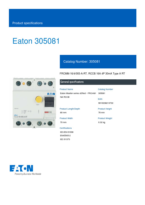
Eaton 305081FRCMM-16/4/003-A-RT. RCCB 16A 4P 30mA Type A RTGeneral specificationsEaton Moeller series xEffect - FRCmM-NA RCCB305081901023821372280 mm 76 mm 70 mm 0.32 kgIEC/EN 61008 EN45545-2 IEC 61373Product NameCatalog Number EANProduct Length/Depth Product Height Product Width Product Weight CertificationsFour-pole16 A10 kA with back-up fuse30 mAPulse-current sensitivePartly surge-proof 250 A 250 A (8/20 μs) surge-proof 240 V AC / 415 V AC415 V440 V4 kV0.03 A0.03 A50 Hz / 60 Hz63 A (max. admissible back-up fuse) A500 A16 A gG/gL10 kA0.25 kA196 V AC - 264 V AC24000 operationsApplicationNumber of poles Amperage RatingRated short-circuit strength Fault current rating Sensitivity typeImpulse withstand current Type Voltage rating (IEC/EN 60947-2)Rated operational voltage (Ue) - maxRated insulation voltage (Ui)Rated impulse withstand voltage (Uimp) Rated fault current - minRated fault current - maxFrequency ratingShort-circuit ratingLeakage current typeRated residual making and breaking capacity Admissible back-up fuse overload - max Rated short-time withstand current (Icw) Surge current capacityTest circuit rangePollution degreeLifespan, electricalxEffect - Switchgear for industrial and advanced commercial applications Switchgear for industrial and advanced commercial applicationsFRCmMResidual current circuit breakersType A45 mm470 mm (4 SU)70.5 mmQuick attachment with 2 latch positions for DIN-rail IEC/EN 60715DIN railAs requiredIP20, IP40 with suitable enclosureIP20White / blueTwin-purpose terminals1.5 mm² - 35 mm²1.5 mm²35 mm²16 mm² (2x)1.5 mm²16 mm²M5 (with cross-recessed screw as defined in EN ISO 4757-Z2, PZ2)Finger and hand touch safe, DGUV VS3, EN 5027416 A0.73 W2.9 W-25 °C55 °CMeets the product standard's requirements.Meets the product standard's requirements.Meets the product standard's requirements.Meets the product standard's requirements.Meets the product standard's requirements.Does not apply, since the entire switchgear needs to be evaluated.Does not apply, since the entire switchgear needs to be evaluated.Meets the product standard's requirements.Does not apply, since the entire switchgear needs to be evaluated.Meets the product standard's requirements.FrameWidth in number of modular spacingsBuilt-in width (number of units)Built-in depthMounting MethodMounting positionDegree of protectionStatus indicationTerminals (top and bottom)Terminal capacity (solid wire)Connectable conductor cross section (solid-core) - min Connectable conductor cross section (solid-core) - max Terminal capacity (stranded cable)Connectable conductor cross section (multi-wired) - min Connectable conductor cross section (multi-wired) - max Terminal capacity (cable)Terminal protection Rated operational current for specified heat dissipation (In) Heat dissipation per pole, current-dependentEquipment heat dissipation, current-dependentAmbient operating temperature - minAmbient operating temperature - max10.2.2 Corrosion resistance10.2.3.1 Verification of thermal stability of enclosures10.2.3.2 Verification of resistance of insulating materials to normal heat10.2.3.3 Resist. of insul. mat. to abnormal heat/fire by internal elect. effects10.2.4 Resistance to ultra-violet (UV) radiation10.2.5 Lifting10.2.6 Mechanical impact10.2.7 Inscriptions10.3 Degree of protection of assemblies10.4 Clearances and creepage distances10.5 Protection against electric shock2 Nm - 2.4 NmRed / green0.8 mm - 2 mm 20000 operations-35 °C60 °C25-55 °C / 90-95% relative humidity according to IEC 60068-2Does not apply, since the entire switchgear needs to be evaluated.Does not apply, since the entire switchgear needs to be evaluated.Is the panel builder's responsibility.Is the panel builder's responsibility.Is the panel builder's responsibility.Is the panel builder's responsibility.Is the panel builder's responsibility.The panel builder is responsible for the temperature rise calculation. Eaton will provide heat dissipation data for the devices.Is the panel builder's responsibility. The specifications for the switchgear must be observed.Is the panel builder's responsibility. The specifications for the switchgear must be observed.The device meets the requirements, provided the information in the instruction leaflet (IL) is observed.Starting at 40 °C, the max. permissible continuous current decreases by 2.5% for every 1 °Ceaton-rcd-application-guide-br019003en-en-us.pdf eaton-xeffect-frcmm-na-rccb-catalog-ca003019en-en-us.pdfeaton-xeffect-industrial-switchgear-range-catalog-ca003002en-en-us.pdf 03_FRCm._181019DA-DC-03_FRCmTightening torque Contact position indicator color Busbar material thickness Lifespan, mechanical Permitted storage and transport temperature - min Permitted storage and transport temperature - max Climatic proofing10.6 Incorporation of switching devices and components 10.7 Internal electrical circuits and connections 10.8 Connections for external conductors 10.9.2 Power-frequency electric strength 10.9.3 Impulse withstand voltage 10.9.4 Testing of enclosures made of insulating material 10.10 Temperature rise10.11 Short-circuit rating10.12 Electromagnetic compatibility10.13 Mechanical functionSpecial featuresApplication notesCataloguesCertification reportsEaton Corporation plc Eaton House30 Pembroke Road Dublin 4, Ireland © 2023 Eaton. All rights reserved. Eaton is a registered trademark.All other trademarks areproperty of their respectiveowners./socialmediaeaton-xeffect-faz-na,-mcb-dimensions.jpg Mas_frcmmeaton-circuit-breaker-xeffect-frcmm-na-rccb-dimensions.eps eaton-305081-3d-model.stp eaton-305081-drawing.dwg eaton-xeffect-frcmm-rccb-wiring-diagram-002.jpgeaton-circuit-breaker-xeffect-frcmm-rccb-wiring-diagram-002.epsDrawingsmCAD modelWiring diagrams。
缆绳 澳大利亚标准

在澳大利亚,缆绳的标准是由澳大利亚标准(AS)所规定的。
具体来说,AS 1187.1-2009和AS 1187.2-2009这两个标准规定了缆绳的分类、标记、性能要求和测试方法等内容。
根据AS 1187.1-2009标准,缆绳按照其强度等级(即能够承受的最大拉力)被分为五类,分别是:
1. 低强度缆绳(Low strength):强度等级低于33.3kN(约为3.3吨)。
2. 中等强度缆绳(Moderate strength):强度等级为3
3.3kN至66.7kN(约为3.3吨至6.7吨)。
3. 高强度缆绳(High strength):强度等级为66.7kN至133.4kN (约为6.7吨至13.3吨)。
4. 超高强度缆绳(Super high strength):强度等级为133.4kN 至266.8kN(约为13.3吨至26.7吨)。
5. 特高强度缆绳(Extra high strength):强度等级超过26
6.8kN (约为26.7吨)。
此外,根据AS 1187.2-2009标准,缆绳还应满足某些特定的性能要求,例如耐磨性、耐腐蚀性、柔韧性等。
这些要求是根据具体的使用环境和需求来确定的。
在选择缆绳时,需要根据具体的使用场景和需求来选择合适的类型和规格。
例如,在海上石油平台或大型船舶上需要使用高强度、耐磨、耐腐蚀的缆绳;而在建筑工地或小型船舶上则可能需要使用轻便、柔韧的缆绳。
总之,在选择缆绳时需要根据具体的使用环境和需求来选择合适的类型和规格,并确保其符合澳大利亚标准(AS)的要求。
各国电源插头与电源线标准
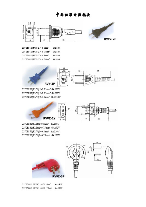
中国标准电源插头227IEC42(RVB)2×0.5mm² 6A250V227IEC42(RVB)2×0.75mm² 6A250V227IEC52(RVV)2×0.5mm² 6A250V227IEC52(RVV)2×0.75mm² 6A250V227IEC52(RVV) 2×0.75mm² 6A250V227IEC53(RVV) 2×0.75mm² 6A250V227IEC53(RVV) 2×1.0mm² 10A250V227IEC42(RVB)2×0.5mm² 6A250V227IEC42(RVB)2×0.75mm² 6A250V227IEC52(RVV)2×0.5mm² 6A250V227IEC52(RVV)2×0.75mm² 6A250V227IEC52(RVV)3×0.5mm² 6A250V227IEC52(RVV)3×0.75mm² 6A250V227IEC53(RVV)3×0.75mm² 6A250V227IEC53(RVV)3×1.0mm² 10A250V227IEC52(RVV)3×0.5mm² 6A250V227IEC52(RVV)3×0.75mm² 6A250V227IEC53(RVV)3×0.75mm² 6A250V227IEC53(RVV)3×1.0mm² 10A250V227IEC52(RVV)3×0.5mm² 6A250V227IEC52(RVV)3×0.75mm² 6A250V227IEC53(RVV)3×0.75mm² 6A250V227IEC53(RVV)3×1.0mm² 10A250VRX 300/300V 3×0.75mm² 6A250VRX 300/300V 3×1.0mm² 10A250V欧洲标准电源插头H03VVH2 -F2X0.5mm² 10/16A250V H03VVH2 -F2X0.75mm²10/16A250V H03VV-F2X0.5mm² 10/16A250V H03VV-F2X0.75mm²10/16A250V H05VVH2 -F2X0.75mm²10/16A250V H05VVH2 -F2X1.0mm²10/16A250V H05VV-F2X0.75mm²10/16A250VH05VV-F2X1.0mm²10/16A250VH03VVH2 -F2X0.5mm² 2.5A250VH03VVH2 -F2X0.75mm² 2.5A250VH03VV-F2X0.5mm² 2.5A250VH03VV-F2X0.75mm² 2.5A250VH05VVH2 -F2X0.75mm²10A250VH05VVH2 -F2X1.0mm²10A250VH05VV-F2X0.75mm²10A250VH05VV-F2X1.0mm²10A250VH03VVH2 -F2X0.5mm² 2.5A250VH03VVH2 -F2X0.75mm² 2.5A250VH03VV-F2X0.5mm² 2.5A250VH03VV-F2X0.75mm² 2.5A250VH05VVH2 -F2X0.75mm²10A250VH05VVH2 -F2X1.0mm²10A250VH05VV-F2X0.75mm²10A250VH05VV-F2X1.0mm²10A250VH03VV-F3G0.5mm² 10/16A250V H03VV-F3G0.75mm²10/16A250V H05VV-F3G0.75mm²10/16A250V H05VV-F3G1.0mm²10/16A250V H05VV-F3G1.5mm²10/16A250VH03VV-F3G0.5mm² 10/16A250V H03VV-F3G0.75mm²10/16A250V H05VV-F3G0.75mm²10/16A250V H05VV-F3G1.0mm²10/16A250V H05VV-F3G1.5mm²10/16A250VH03VV-F3G0.5mm² 10A250VH03VV-F3G0.75mm²10A250VH05VV-F3G0.75mm²10A250VH05VV-F3G1.0mm²10A250VH03VV-F3G0.5mm² 10A250VH03VV-F3G0.75mm²10A250VH05VV-F3G0.75mm²10A250VH05VV-F3G1.0mm²10A250V227IEC52(RVV)3X0.75mm²10A250V 227IEC53(RVV)3X0.75mm²10A250V 227IEC53(RVV)3X1.0mm²10A250V H03VV-F3G0.75mm²6A250VH05VV-F3G0.75mm²10A250V H05VV-F3G1.0mm²10A250V227IEC52(RVV)3X0.75mm²10A250V227IEC53(RVV)3X0.75mm²10A250V227IEC53(RVV)3X1.0mm²10A250VH03VV-F3G0.75mm²6A250VH05VV-F3G0.75mm²10A250VH05VV-F3G1.0mm²10A250V澳大利亚标准电源插头SAAH05VVH2 -F2X0.75mm²7.5A250VH05VV-F2X0.75mm²7.5A250VH05VV-F2X1.0mm²10A250VH05VVH2 -F2X0.75mm²7.5A250VH05VV-F2X0.75mm²7.5A250V H05VV-F2X1.0mm²10A250VH05VV-F3G0.75mm²7.5A250VH05VV-F3G1.0mm²10A250VH05VV-F3G1.5mm²15A250V美国标准电源插头C-ULSPT-118AWG/2CSPT-218AWG/2CSPT-216AWG/2CSPT-318AWG/2CSPT-316AWG/2CSVT18AWG/2CSVT17AWG/2CNISPT-118AWG/2C NISPT-218AWG/2CSVT18AWG/2CSVT17AWG/2CST18AWG/2CST16AWG/2CSJT18AWG/2CSJT16AWG/2C NISPT-118AWG/2C NISPT-218AWG/2CSVT18AWG/2CSVT17AWG/2CSVT18AWG/2C(齿形) SVT17AWG/2C(齿形) ST18AWG/2CST16AWG/2CSPT-118AWG/3CSPT-218AWG-16AWG/3CSPT-318AWG-16AWG/3CSVT18AWG- 17AWG/3CSVT18AWG-17AWG/3C(齿形)ST18AWG-16AWG/3CSJT 18AWG-16AWG/3CSVT18AWG/3CSVT17AWG/3CSVT18AWG/3C(齿形)SVT17AWG/3C(齿形)ST18AWG/3CST16AWG/3CSJT 16AWG/3CSJT 18AWG/3C日本标准电源插头VFF2X0.75mm²7A125VVCTF2X0.75mm²7A125VVCTFK2X0.75mm²7A125V以色列南非英国电源插头H03VV-F3G0.75mm²H05VV-F3G0.75mm²H05VV-F3G1.0mm²H05VV-F3G1.5mm²H03VV-F3G0.75mm²H05VV-F3G0.75mm²H05VV-F3G1.0mm²H05VV-F3G1.5mm²H03VV-F3G0.5mm²H03VV-F3G0.75mm²H05VV-F3G0.75mm²H05VV-F3G1.0mm²H05VV-F3G1.5mm²认证国家名称代号CENELEC欧洲电气标准委员会奥地利电气机械标准欧洲标准电源线·标准:DIN VDE0281·型号:H03VVH2-F H03VV-FH05VVH2-F H05VV-F·额定电压:H03 300/300VH05 300/500V·应用:H03型适用小功率家用电器、电动工具及动力照明等。
澳大利亚标准电缆材料中英文对照
澳大利亚标准电缆材料中英文对照澳大利亚标准电缆材料中英文对照,希望对大家有用 4.1 Insulating material(绝缘类)4.2 Sheathing material(护套类)a EPR 乙丙橡胶a 3V-75 75℃降低机械性能,易剥离的PVC b HFI-75-TP 75℃低压无卤阻燃热塑性聚烯烃 b 3V-90 90℃降低机械性能,易剥离的PVC c HFI-90-TP 90℃低压无卤阻燃热塑性聚烯烃 c 4V-75 75℃PVC d PE 70℃聚乙烯d 5V-90 90℃PVC e PP 80℃聚丙烯e E-110-R 110℃交联弹性体f R-CPE-90 90℃氯化聚乙烯f GP-75-TPE 75℃复合弹性体g R-CSP-90 90℃氯磺化聚乙烯g GP-85-PCP 85℃氯丁橡胶h R-E-110 110℃交联弹性体h GP-90-CPE 90℃氯化聚乙烯i R-EP-90 90℃乙烯丙烯共聚物i GP-90-CSP 90℃氯磺化聚乙烯j R-EP-105 105℃乙烯丙烯共聚物j GP-100-CPE 100℃氯化聚乙烯k R-HF-90 90℃低烟无卤阻燃交联复合弹性体k GP-100-CSP 100℃氯磺化聚乙烯l R-HF-110 110℃低烟无卤阻燃交联复合弹性体l GP-150-S 150℃硅烷化合物m R-S-150 150℃交联硅烷化合物m HD-85-PCP 重载版85℃氯丁橡胶n R-S-200 200℃交联硅烷化合物n HD-90-CPE 重载版90℃氯化聚乙烯o TP-90 90℃热塑性高分子o HD-90-CSP 重载版90℃氯磺化聚乙烯p TPE-75 75℃热塑性弹性体p HD-105-CPE 重载版105℃氯化聚乙烯q V-75 75℃PVC q HD-105-CSP 重载版105℃氯磺化聚乙烯r V-90 or V-90HT 90℃PVC r HDPE 高密度聚乙烯s X-90 90℃XLPE s HF-90-R 90℃低烟无卤阻燃交联弹性体t X-90UV 90℃XLPE 抗紫外线t HF-110-R110℃低烟无卤阻燃交联弹性体u X-HF-90 90℃低烟无卤阻燃交联聚烯烃u HFS-75-TP 75℃低压无卤阻燃热塑性聚烯烃v X-HF-110 110℃低烟无卤阻燃交联聚烯烃v HFS-90-TP 90℃低压无卤阻燃热塑性聚烯烃w XLPE 90℃XLPE 与(s同一种材料w HFS-110-TP 110℃低压无卤阻燃热塑性聚烯烃x XR-EP-90 改性的乙烯丙烯共聚物x LLDPE 线性低密度聚乙烯y XV-75 75℃交联聚氯乙烯y PE 聚乙烯z XV-90 90℃交联聚氯乙烯z XHD-85-PCP 85℃超重载版氯丁橡胶aa XHD-90-CPE 90℃超重载版氯化聚乙烯ab XHD-90-CSP 90℃超重载版氯磺化聚乙烯注V-90HT可在105 ℃每年平均运行500小时。
澳大利亚标准 as 1154.1
澳大利亚标准AS 1154.1是指澳大利亚电线和电缆的规范标准,涉及电缆的结构、尺寸、性能和试验方法等方面。
该标准规定了电缆的基本要求、电缆的组成结构、电缆的规格尺寸和试验方法等,以确保电缆的质量和安全性。
AS 1154.1-2009是该标准的最新版本,规定了电线和电缆的制造和试验要求,以确保其符合澳大利亚和其他国际标准。
该标准适用于所有类型的电线和电缆,包括室内和室外使用的电缆,以及用于商业和工业应用的电缆。
根据AS 1154.1-2009标准,电线和电缆必须符合以下要求:
电线和电缆的尺寸和结构应符合规范要求,以确保其能够承受预期的负载和环境条件。
电线和电缆的材料和组成应符合规范要求,以确保其具有所需的耐火、电气、机械和环境性能。
电线和电缆的制造过程应确保其质量和安全性,并按照规范要求进行检验和试验。
电线和电缆应按照规范要求进行标识和标记,以确保其识别和安装的正确性。
总之,AS 1154.1-2009是澳大利亚电线和电缆的规范标准,以确保其质量和安全性。
该标准适用于所有类型的电线和电缆,包括室内和室外使用的电缆,以及用于商业和工业应用的电缆。
澳大利亚电缆标准
AS/NZS 1429.1:2006 AS/NZS 1429.1:2006Australian/New Zealand Standard™Electric cables—Polymeric insulatedPart 1: For working voltages 1.9/3.3(3.6) kV up to and including 19/33 (36)kVAS/NZS 1429.1:2006This Joint Austra lia n/New Zea la nd Sta nda rd wa s prepa red by Joint Technica l Committee EL-003, Electric Wires a nd Ca bles. It wa s a pproved on beha lf of the Council of Sta nda rds Austra lia on 3 April 2006 a nd on beha lf of the Council of Standards New Zealand on 31 March 2006.This Standard was published on 21 April 2006.The following are represented on Committee EL-003:Australasian Railway AssociationAustralian Electrical and Electronic Manufacturers AssociationAustralian Industry GroupCanterbury Manufacturers Association New ZealandDepartment of Primary Industries, Mine Safety (NSW)Electrical Contractors Association of New ZealandElectrical Regulatory Authorities CouncilEnergy Networks AssociationEngineers AustraliaMinistry of Economic Development (New Zealand)Keeping Standards up-to-dateSta nda rds a re living documents which reflect progress in science, technology a nd systems. To ma inta in their currency, a ll Sta nda rds a re periodica lly reviewed, a nd new editions re published. Between editions, mendments m y be issued. Sta nda rds ma y a lso be withdra wn. It is importa nt tha t rea ders a ssure themselves they a re using a current Sta nda rd, which should include a ny a mendments which may have been published since the Standard was purchased.Detailed information about joint Australian/New Zealand Standards can be found by visiting the Sta nda rds Web Shop a t www.sta nda .a u or Sta nda rds New Zea la nd web site a t www.sta nda a nd looking up the releva nt Sta nda rd in the on-line catalogue.Alterna tively, both orga niza tions publish a n a nnua l printed Ca ta logue with full deta ils of a ll current Sta nda rds. For more frequent listings or notifica tion of revisions, a mendments a nd withdra wa ls, Sta nda rds Austra lia a nd Sta nda rds New Zea la nd offer a number of upda te options. For informa tion a bout these services, users should contact their respective national Standards organization.We a lso welcome suggestions for improvement in our Sta nda rds, a nd especia lly encoura ge rea ders to notify us immedia tely of a ny a ppa rent ina ccura cies or a mbiguities. Plea se a ddress your comments to the Chief Executive of either Sta nda rds Austra lia or Sta nda rds New Zea la nd a t the a ddress shown on the ba ck cover.This Standard was issued in draft form for comment as DR 05363.AS/NZS 1429.1:2006Australian/New Zealand Standard™Electric cables—Polymeric insulated Part 1: For working voltages 1.9/3.3 (3.6) kV up to and including 19/33 (36) kVOriginated as AS 1429—1979.Jointly revised and designated AS/NZS 1429.1:2000.Third edition 2006.COPYRIGHT© Standards Australia/Standards New ZealandAll rights are reserved. No part of this work may be reproduced or copied in any form or by ny me ns, electronic or mech nic l, including photocopying, without the written permission of the publisher.Jointly published by Standards Australia, GPO Box 476, Sydney, NSW 2001 and Standards New Zealand, Private Bag 2439, Wellington 6020AS/NZS 1429.1:2006 2PREFACEThis Standard was prepared by the Joint Standards Australia/Standards N ew Zealand Committee EL-003, Electric Wires and Cables, to supersede AS/NZS 1429.1:2000.This Standard differs from the previous edition in the following significant ways:(a) The range of conductor sizes has been expanded to 1 600 mm2.(b) The method of specifying the thickness of insulation, separation sheath, metal sheathand oversheath has been aligned with IEC 60502-2.(c) MDPE has replaced PE as an optional oversheathing material.(d) Cables with collectively screened constructions are no longer specified.(e) The requirement for a qualification test report has been added.(f) The range of approval has been modified.(g) The recommended diameter of drum barrel and minimum installation bending radiushas been extended to cover triplex cables.(h) The sample test requirement has become mandatory.In the preparation of this Standard, consideration was given to the following publications and acknowledgment is made of the assistance received:IEC 60502-2, Power cables with extruded insulation and their accessories for ratedvoltages from 1 kV (U m = 1,2 kV) up to 30 kV (U m = 36 kV), Part 2: Cables for ratedvoltages from 6 kV (U m = 7,2 kV) up to 30 kV (U m = 36 kV)IEC 60811, Common test methods for insulating and sheathing materials of electric cables and optical cables (all Parts)The nominal cross-sectional areas of the conductors specified herein are identical with the values specified in AS/N ZS 1125, Conductor s in insulated electr ic cables and flexible cords.The dimensions for insulation and oversheath thicknesses are identical with the values recommended in IEC 60502. Certain tests and criteria in this Standard are more stringent than those in IEC 60502.Two types of insulation compounds are specified in this Standard, namely insulation comprising cross-linked polyethylene (XLPE) and insulation comprising ethylene propylene rubber (EPR).Although the Standard provides tables of insulation thicknesses and the necessary information to establish precisely the dimensions of the cable protective coverings, no cable dimension tables are provided owing to the variety of cable constructions that could possibly affect such dimensions.The terms ‘normative’ and ‘informative’ have been used in this Standard to define the application of the appendix to which they apply. A ‘normative’ appendix is an integral part of a Standard, whereas an ‘informative’ appendix is only for information and guidance.Statements expressed in mandatory terms in notes to tables and figures are deemed to be requirements of this Standard.AS/NZS 1429.1:20063CONTENTSPage SECTION 1 SCOPE AND GENERAL1.1 SCOPE (4)1.2 REFEREN CED DOCUMEN TS (4)1.3 DEFIN ITION S (5)1.4 VOLTAGE DESIGN ATION (7)1.5 MAXIMUM CONDUCTOR TEMPERATURE (8)SECTION 2 CONSTRUCTION2.1 CON DUCTORS (9)2.2 CON DUCTOR SCREEN (9)2.3 IN SULATION (9)2.4 IN SULATION SCREEN (11)2.5 METALLIC SCREEN (12)2.6 IDENTIFICATION OF CORES (12)2.7 LAYIN G-UP (13)2.8 FILLERS, BINDERS, AND BARRIER TAPES (13)2.9 METAL SHEATH (OPTIONAL) (13)2.10 SEPARATION SHEATH (14)2.11 BEDDIN G (15)2.12 ARMOUR (OPTION AL) (16)2.13 OVERSHEATH (17)2.14 WATER-BLOCKIN G (OPTION AL) (18)2.15 PROTECTION FROM INSECT ATTACK (OPTIONAL) (18)2.16 CABLE IDEN TIFICATION (19)2.17 METRE MARKING ON CABLE (OPTIONAL) (19)2.18 PREPARATION FOR DELIVERY (19)2.19 MARKING OF DRUMS (19)SECTION 3 TESTS3.1 GEN ERAL (20)3.2 QUALIFICATION TEST REPORT (20)3.3 HIGH VOLTAGE TEST FOR 5 MIN (24)3.4 BENDING TEST FOLLOWED BY PARTIAL DISCHARGE TEST (24)3.5 MEASUREMENT OF DDF (TAN δ) AS A FUNCTION OF VOLTAGE (25)3.6 MEASUREMENT OF DDF (TAN δ) AT ELEVATED TEMPERATURE (25)3.7 HEAT CYCLING FOLLOWED BY PARTIAL DISCHARGE TEST (25)3.8 IMPULSE WITHSTAND TEST FOLLOWED BY A HIGH VOLTAGE TEST (25)3.9 HIGH VOLTAGE A.C. TEST FOR 4H (26)3.10 RE-QUALIFICATION TESTS (26)APPENDICESA THE FICTITIOUS CALCULATION METHOD FOR THE DETERMINATION OFTHE DIMENSIONS OF PROTECTIVE COVERINGS (28)B PURCHASIN G GUIDELIN ES (31)C WATER PENETRATION TEST (32)D RECOMMENDED DIAMETER OF DRUM BARREL AND MINIMUMINSTALLATION BENDING RADIUS FOR CABLES (34)E SELECTION AND RETEST PROCEDURE FOR SAMPLE TESTS (36)F TESTS AFTER INSTALLATION (37)G ROUNDING OF NUMBERS (38)AS/NZS 1429.1:2006 4STANDARDS AUSTRALIA/STANDARDS NEW ZEALANDAustralian/New Zealand Standard Electric cables—Polymeric insulatedPart 1: For working voltages 1.9/3.3 (3.6) kV up to and including 19/33 (36) kVS E C T I O N 1 S C O P E A N D G E N E R A L1.1 SCOPEThis Standard specifies requirements for cross-linked polyethylene (XLPE) and ethylenepropylene rubber (EPR) insulated cables for fixed installations for electricity supply atworking voltages 1.9/3.3 (3.6) up to and including 19/33 (36) kV.NOTE: Optional requirem ents for m etal sheath, arm our, water-blocking, protection from insectattack and m etre m arking on cable are provided in Clauses 2.9, 2.12, 2.14, 2.15 and 2.17respectively.1.2 REFERENCED DOCUMENTSThe following documents are referred to in this Standard:AS1931 High-voltage test techniques (all Parts)3983 Metal drums for insulated electric cables and bare conductorsAS/N ZS1125 Conductors in insulated electric cables and flexible cords1429 Electric cables—Polymeric insulated1429.2 Part 2: For working voltages above 19/33 (36) kV up to and including76/132 (145) kV1660 Test methods for electric cables, cords and conductors1660.1 Method 1: Conductors and metallic components1660.2.1 Method 2.1: Insulation, extruded semi-conductive screens and non-metallicsheaths—Methods for general application1660.2.2 Method 2.2: Insulation, extruded semi-conductive screens and non-metallicsheaths—Methods specific to elastomeric, XLPE and XLPVCmaterials1660.2.5 Method 2.5: Insulation, extruded semi-conductive screens and non-metallicsheaths—Methods specific to cables above 1 kV1660.3 Method 3: Electrical tests2857Timber drums for insulated electric cables and bare conductors 2893Electric cables—Lead and lead alloy sheaths—Composition 3808Insulating and sheathing materials for electric cables 3863 Galvanized mild steel wire for armouring cables5AS/NZS 1429.1:2006IEC60949 Calculation of thermally permissible short-circuit currents, taking into account non-adiabatic heating effects60986 Short-circuit temperature limits of electric cables with rated voltage from6 kV (U m = 7,2 kV) up to 30 kV (U m = 36 kV)1.3 DEFINITIONSFor the purposes of this Standard, the relevant definitions in the referenced Standards andthose below apply.1.3.1 Approximate valueA value which is neither guaranteed nor checked.1.3.2 Conductor screenA layer or layers of non-metallic semiconductive material applied directly over theconductor.1.3.3 Core (of a cable)An assembly comprising a conductor, semiconductive conductor screen, insulation andsemiconductive insulation screen.1.3.4 Direction of layThe slope of the core, screen wire or armour wire, or the like when the cable is heldvertically.The direction of lay is right-hand when the slope is in the direction of the central part of theletter Z, and left-hand when the slope is in the direction of the central part of the letter S.1.3.5 Fictitious valuesValues calculated according to an equation which is based only on the cross-sectional areaof a conductor, the number of cores and specified component dimensions, and whichignores conductor shape, degree of compaction of conductors and the possibility ofcomponents having dimensions other than specified. (See Appendix A.)1.3.6 Gross cross-sectional areaWith respect to the wire screens, the product of the calculated cross-sectional area of onescreen wire multiplied by the total number of screen wires in the cable.1.3.7 Individual screenA metallic screen applied over each core.1.3.8 Insulation screenA layer or layers of non-metallic semiconductive material applied directly over theinsulation of each core.1.3.9 Length of layWith respect to the wire screen, the axial distance between successive turns of the helix of ascreen wire.1.3.10 Maximum conductor temperatureThe maximum temperature resulting from the combined effect of all contributing thermalconditions. It varies depending on the mode of operation and is limited to the valuesspecified in Table 1.2.AS/NZS 1429.1:2006 61.3.11 Nominal valueA value by which a quantity is designated and which is often used in tables. Usually, inrelation to this Standard, nominal values give rise to values to be checked by measurements taking into account specified tolerances.1.3.12 Non-hygroscopicWhen applied to a material, means that the material after being preconditioned in an oven at50 ±5°C for 24 ±1 h and allowed to cool in a desiccator, does not absorb more than 5% byweight of moisture during a 48 h treatment in a relative humidity of 95 ±4% at a temperature of 20 ±5°C.1.3.13 Qualification test reportA report of results obtained from all routine, sample and type tests.1.3.14 Re-qualification testsTests made by the manufacturer on an already qualified range of cables following any changes in critical cable component materials, the method of cable manufacture or production line.1.3.15 Routine testsTests made by the manufacturer on each manufactured length of cable to check that each length meets the specified requirements.1.3.16 Sample testsTests made by the manufacturer on samples of completed cable, or components taken froma completed cable, at a specified frequency, so as to verify that the finished product meetsthe specified requirements.1.3.17 ShallIndicates that a statement is mandatory.1.3.18 ShouldIndicates a recommendation.1.3.19 Triplex cableAn assembly of three metallic screened and oversheathed cores.1.3.20 Type testsTests made before supplying, on a general commercial basis, a type of cable covered by this Standard, in order to demonstrate satisfactory performance characteristics to meet the intended application.1.3.21 Water-blocking, longitudinalPrevention or reduction of water migration along the length of the cable. This may consist of design options in the area of the metallic screen and/or the conductor.1.3.22 Water-blocking, radialPrevention or reduction of water ingress towards the insulation by permeation through the outer part of the cable.7AS/NZS 1429.1:20061.4 VOLTAGE DESIGNATIONIndication of the rated voltages shall be expressed in the form U0/U (U m)whereU0is the r.m.s. power frequency voltage to earth of the supply system for which the cable is designedU is the r.m.s. power frequency voltage between phases of the supply system for which the cable is designedU m is the maximum r.m.s. power frequency voltage between any two phase conductors for which cables and accessories are designed. It is the highestvoltage that can be sustained under normal operating conditions at any timeand at any point in a system. It excludes temporary voltage variations due tofault conditions and sudden disconnection of large loads.The rated voltages U0/U (U m) of the cables recognized in this Standard are1.9/3.3 (3.6) kV, 3.8/6.6 (7.2) kV, 6.35/11 (12) kV, 12.7/22 (24) kV and19/33 (36) kV.The rated voltage of the cable for a given application shall be suitable for theoperating conditions in the system in which the cable is used. To facilitate theselection of the cable, systems are divided into the following three categories:(a)Categor y A This category comprises those systems in which any phase conductorthat comes in contact with earth or an earth conductor, is disconnected from thesystem within 1 min.(b)Category B This category comprises those systems which, under fault conditions,are operated for a short time with one phase earthed. This period should not exceed1 h. For cables covered by this Standard, a longer period, not exceeding 8 h on anyoccasion, can be tolerated. The total duration of earth faults in any year should notexceed 125 h.(c)Category C This category comprises all systems which do not fall into Category Aor B.NOTE: It should be realized that in a system where an earth fault is not autom atically andpromptly isolated, the extra stresses on the insulation of cables during the earth fault reducethe life of the cables. If the system is expected to be operated fairly often with a permanentearth fault, it may be advisable to classify the system in Category C.The values of U0/U(U m) for cables to be used in three-phase systems should be as listed inTable 1.1.TABLE 1.1RECOMMENDED RATED VOLTAGESRated voltage U o/U(U m) kVHighest system voltage(U m) kVCategories A and B Category C3.6 7.2 12.0 1.9/3.3 (3.6)3.8/6.6 (7.2)6.35/11 (12)3.8/6.6 (7.2)6.35/11 (12)12.7/22(24)24.0 36.0 12.7/22 (24)19/33 (36)19/33 (36)38/66(72)** Cable of this rating is covered by AS/NZS 1429.2.AS/NZS 1429.1:2006 81.5 MAXIMUM CONDUCTOR TEMPERATUREThe maximum conductor temperature of cables for nominated conditions shall be as specified in Table 1.2.TABLE 1.2MAXIMUM CONDUCTOR TEMPERATURE FOR THE SPECIFIED INSULATION MATERIAL AND FOR DIFFERENT MODES OF OPERATION1 2 3 4Maximum conductor temperature, °C (Note 1)Insulationmaterial Continuous operation Emergency operation(Note 2) Short-circuit operation (5 s maximum duration)XLPE EPR 9090105130250250NOTES:1 The ma ximum conductor tempera tures specified are based upon the properties of the insula tionmaterials but in practice may need to be derated to take account of—(a) joints and terminations; and(b) installation conditions, such as proximity to other circuits and services.2 The emergency opera tion tempera tures a re a pplica ble for a n a vera ge over severa l yea rs, of notmore than one period per year. No period should exceed 36 h and there should not be more than three periods in any 12 consecutive months.S E C T I O N2C O N S T R U C T I O N2.1 CONDUCTORSConductors shall have a circular profile and consist of either aluminium or plain or tinned copper, complying with the requirements of AS/NZS 1125.Measures may be taken to achieve longitudinal water-blocking.NOTE: See the purchasing guidelines set out in Appendix B.2.2 CONDUCTOR SCREEN2.2.1 Material and applicationAll cables shall have an extruded, cross-linked, semiconductive screen applied on the conductor. A semiconductive tape may be applied as part of the conductor screen and, where used, shall be applied directly on the conductor, preceding the extruded layer.2.2.2 ThicknessThe thickness of the extruded layer shall be not less than that specified in Table 3.1.2.2.3 Removal from conductorThe conductor screen shall be readily removable from the conductor.2.2.4 Outer surfaceThe outer surface of the conductor screen shall be free of irregularities larger than those permitted in Table 3.1.2.2.5 TestsTests on the conductor screen and the category of each test shall be as specified in Table 3.1.2.2.6 Pass criteriaThe conductor screen shall comply with the requirements specified in Table 3.1.2.3 INSULATION2.3.1 MaterialInsulation shall be XLPE (including materials known as tree-retardant XLPE) or EPR and shall comply with the requirements of AS/NZS 3808.2.3.2 ApplicationThe insulation shall bond to the conductor screen so that it is not possible to separate the two without damage at their interface. The insulation shall be homogeneous.2.3.3 ThicknessThe nominal thickness of insulation (t i) and the insulation minimum thickness at any point shall be in accordance with Tables 2.1 and 2.2. The values for minimum at any point are derived from the equation: 0.90 t i− 0.10 mm.2.3.4 ConcentricityThe thickness of insulation shall be measured at the thickest point (t max ) and the thinnest point (t min ) and the following concentricity requirement shall be met.15.0maxminmax ≤t t -t 2.3.5 TestsTests on the insulation and the category of each test shall be as specified in Table 3.1. 2.3.6 Pass criteriaThe insulation shall comply with the requirements specified in Table 3.1.TABLE 2.1INSULATION THICKNESS FOR XLPE INSULATED CABLES1 2 3 4 5 6 7 8 9 10 11 Nominal insulation thickness (t i ) and minimum thickness at any point of insulation for cable ratedvoltage of—1.9/3.3 (3.6) kVmm 3.8/6.6 (7.2) kVmm6.35/11 (12) kVmm12.7/22 (24) kVmm19/33 (36) kVmmNominal cross-sectional area of conductor mm 2Min. point t i Min. point t i Min. point t i Min. point t i Min. point t i16 25 35 1.70 1.70 1.70 2.02.0 2.0 2.15 2.15 2.15 2.5 2.5 2.5 2.96 2.96 2.963.4 3.4 3.4 ——4.85 ——5.5 ——————50 70 95 1.70 1.70 1.70 2.0 2.0 2.0 2.15 2.15 2.15 2.5 2.5 2.5 2.96 2.96 2.96 3.4 3.4 3.4 4.85 4.85 4.85 5.5 5.5 5.5 7.10 7.10 7.10 8.0 8.0 8.0 120 150 185 1.70 1.70 1.70 2.0 2.0 2.0 2.15 2.15 2.15 2.5 2.5 2.5 2.96 2.96 2.96 3.4 3.4 3.4 4.85 4.85 4.85 5.5 5.5 5.5 7.10 7.10 7.10 8.0 8.0 8.0 240 300 400 1.70 1.70 1.70 2.0 2.0 2.0 2.24 2.42 2.60 2.6 2.8 3.0 2.96 2.96 2.96 3.4 3.4 3.4 4.85 4.85 4.85 5.5 5.5 5.5 7.10 7.10 7.10 8.0 8.0 8.0 500 630 800 1.88 2.06 2.24 2.2 2.4 2.6 2.78 2.78 2.78 3.2 3.2 3.2 2.96 2.96 2.96 3.4 3.4 3.4 4.85 4.85 4.85 5.5 5.5 5.5 7.10 7.10 7.10 8.0 8.0 8.0 1 000 1 200 1 6002.42 ——2.8 ——2.78 ——3.2 ——2.96 2.96 2.963.4 3.4 3.44.85 4.85 4.855.5 5.5 5.57.10 7.10 7.108.0 8.0 8.0TABLE 2.2INSULATION THICKNESS FOR EPR INSULATED CABLES1 2 3 4 5 6 7 8 9 10 11Nominal insulation thickness (t i) and minimum thickness at any point of insulation for cable ratedvoltage of—1.9/3.3 (3.6) kVmm 3.8/6.6 (7.2) kVmm6.35/11 (12) kVmm12.7/22 (24) kVmm19/33 (36) kVmmNominal cross-sectional area of conductormm2Min.point t iMin.pointt iMin.pointt iMin.pointt iMin.pointt i16 25 35 1.881.881.882.22.22.22.152.152.152.52.52.52.962.962.963.43.43.4——4.85——5.5——————50 70 95 1.881.882.062.22.22.42.152.152.152.52.52.52.962.962.963.43.43.44.854.854.855.55.55.57.107.107.108.08.08.0120 150 185 2.062.062.062.42.42.42.152.152.152.52.52.52.962.962.963.43.43.44.854.854.855.55.55.57.107.107.108.08.08.0240 300 400 2.062.062.242.42.42.62.242.422.602.62.83.02.962.962.963.43.43.44.854.854.855.55.55.57.107.107.108.08.08.0500 630 800 2.422.422.422.82.82.82.782.782.783.23.23.22.962.962.963.43.43.44.854.854.855.55.55.57.107.107.108.08.08.01 000 1 200 1 600 2.60——3.0——2.78——3.2——2.962.962.963.43.43.44.854.854.855.55.55.57.107.107.108.08.08.02.4 INSULATION SCREEN2.4.1 Material and applicationThe screen shall consist of a layer of extruded, cross-linked, semiconductive compound applied directly over the insulation. A semiconductive tape may be applied as part of the insulation screen and, where used, shall be applied over the extruded insulation screen.2.4.2 ThicknessThe thickness of the extruded layer shall be not less than that specified in Table 3.1.2.4.3 Requirements for stripping insulation screensHand-stripping requirements shall be as follows:(a) Where the insulation screen is designed to be hand-stripped without preconditioning(heating), it shall meet the strippability and adhesion tests specified in tests 4(b) and(c) of Table 3.1.(b) Where the insulation screen is designed to be hand-stripped after preconditioning(heating), the strippability and adhesion requirements specified in tests 4(b) and (c) of Table 3.1 do not apply. However, it shall be possible to peel the screen cleanly from the insulation while the screen is hot.NOTE: In Item(b), the type of screen requiring preconditioning norm ally applies to EPR insulated cables.2.4.4 TestsTests on the insulation screen and the category of each test shall be as specified in Table 3.1.2.4.5 Pass criteriaThe insulation screen shall comply with the requirements specified in Table 3.1.2.5 METALLIC SCREEN2.5.1 GeneralWire screens shall comply with the specific requirements of Clauses 2.5.2 to 2.5.5 inclusive. Metal sheaths (see Clause 2.9) may be used as screens and may be supplemented with wire screens, in continuous electrical contact, to achieve the required electrical fault rating. The screens shall be of a gross cross-sectional area not less than that calculated by the adiabatic method set out in IEC 60986, based on an initial temperature of 80°C.The non-adiabatic method for this calculation may be used when agreed between the purchaser and the supplier and, if used, it shall comply with IEC 60949.For three-core cables, the screens shall be in continuous electrical contact throughout the length of the cable. In which case the gross cross-sectional area of the screen shall be equally shared amongst the three cores.2.5.2 MaterialThe screen wires shall comprise plain or tinned annealed copper wires, generally complying with AS/N ZS 1125. Where tinned screens are provided, wires taken from the completed cable need not comply with the tinning test specified in AS/NZS 1125. All wires shall be of the same nominal diameter and in no case less than 0.60 mm. Wires shall not vary from the nominal diameter by more than 5%.2.5.3 ApplicationThe wires shall be helically applied with a length of lay not exceeding 10 times the pitch circle diameter of the screen wires over the core, and shall be in electrical contact with the core throughout the length of the cable.The design gap, i.e. the gap between adjacent wires when equally spaced, calculated by taking into account the number and nominal diameter of wires and the calculated pitch circle diameter of the metallic screen, shall not exceed 4 mm.For three-core cables, each core shall be screened with the same number of wires.For single-core cables with a metal sheath, the screen shall be applied over semi-conductive tapes over the metal sheath. Where the tape is not of the water-blocking type the tape shall be non-hygroscopic.2.5.4 TestsTests on the wire screen and the category of each test shall be as specified in Table 3.1.2.5.5 Pass criteriaThe wire screen shall comply with the appropriate requirements specified in Table 3.1.2.6 IDENTIFICATION OF CORESThe cores of three-core and triplex cables shall be identified in one of the following ways: (a) By the printed numeral and word 1 ONE, 2 TWO or 3 THREE, as appropriate, on theouter surface of each core.(b) By the printed word RED, WHITE or BLUE, as appropriate, on the outer surface ofeach core.(c) By colour-marking the semiconductive tape or adding coloured strips to each corethroughout the full length of the cable, the colour to be red, white or blue as appropriate.Where identified by printing, the characters shall be in a colour contrasting with the core surface. They shall be applied so that they shall remain legible during the service life of the cable. The height of the individual characters shall be not less than the following values:(i) For conductor of nominal cross-sectional arealess than 70 mm2.................................................................................1.5 mm.(ii) For conductor of nominal cross-sectional areamm2 and larger...............................................................................3.0 mm.70The gap between the end of one set of characters and the beginning of the next set shall be not greater than 150 mm.Where coloured strips are used for identification, their width shall be not less than 3 mm nor more than 5 mm.2.7 LAYING-UPFor three-core cables, the screened cores shall be laid up in a right-hand direction of lay. Unless otherwise requested, fillers and binder/barrier tapes shall be used to form a substantially compact and circular cross-section core assembly with a reasonably smooth surface without creasing of the tapes.For triplex cable, the three individual phase cores shall be laid up with a length of lay not less than 15 times, nor more than 30 times the overall diameter of the circumscribing circle over the laid-up bundled cable. The direction of lay shall be right hand. Fillers and binder tapes are not a requirement.2.8 FILLERS, BINDERS, AND BARRIER TAPESAny fillers, binders and barrier tapes shall be of a non-hygroscopic material, compatible with the cable components with which they are in contact.NOTE: Binder tapes or binder and barrier tapes m ay be required to prevent extruded coverings(e.g. oversheath) from penetrating between screen wires and, particularly where followed by anHDPE sheath (this only applies to single-core cables) to achieve a reasonably sm ooth surface under the extruded coverings. Barrier tapes are also used to separate incom patible non-m etallic materials.2.9 METAL SHEATH (OPTIONAL)2.9.1 GeneralAppropriate precautions are required to prevent corrosion of metal sheaths and to provide adequate mechanical protection, including installation conditions. When the sheath is used as a screen it may require wire screens to provide the required fault current rating. (Refer to Clause 2.5.1).2.9.2 Lead alloy sheath2.9.2.1 GeneralLead alloy sheath barrier should be used for cables permanently immersed in water or where cable might be subject to contamination by hydrocarbons, such as in a petrochemical refinery or similar installation.。
cn-AS NZS 1429[1].1-2006-国选利-何慧审校
![cn-AS NZS 1429[1].1-2006-国选利-何慧审校](https://img.taocdn.com/s3/m/d82a78661ed9ad51f01df218.png)
Australian/New Zealand Standard TM澳大利亚/新西兰标准TMElectric cables—Polymeric insulatedPart 1: For working voltages 1.9/3.3 (3.6) kV up to and including小于等于 19/33 (36) kV电缆-聚合绝缘第一部分:工作电压为1.9/3.3 (3.6) kV时,电力供应小于等于19/33 (36) kV注:此标准的中文翻译仅供参考,如中文翻译和英文含义有出入,以英文为准。
This Joint Australian/New Zealand Standard was prepared by Joint Technical Committee EL-003, Electric Wires and Cables. It was approved on behalf of the Council of Standards Australia on 3 April 2006 and on behalf of the Council of Standards New Zealand on 31 March 2006.本澳/新联合标准由电线和电缆联合技术委员会EL-003编制,并以澳大利亚标准委员会的名义于2006年4月3日获得审批通过,以新西兰标准委员会的名义于2006年3月31日获得审批通过。
This Standard was published on 21 April 2006.本标准于2006年4月21日出版。
The following are represented on Committee EL-003:EL-003委员会由以下单位参加:Australasian Railway Association大洋洲铁路协会Australian Electrical and Electronic Manufacturers Association澳大利亚电气和电子制造商协会Australian Industry Group澳大利亚工业集团Canterbury Manufacturers Association New Zealand新西兰坎特伯雷制造商协会Department of Primary Industries, Mine Safety (NSW)第一产业部,矿山安全(新南威尔士)Electrical Contractors Association of New Zealand新西兰电气承包商协会Electrical Regulatory Authorities Council电气管理机构委员会Energy Networks Association能源网络协会Engineers Australia澳大利亚工程师协会Ministry of Economic Development (New Zealand)经济发展部(新西兰)Keeping Standards up-to-date关于标准的更新Standards are living documents which reflect progress in science, technology and systems. To maintain their currency, all Standards are periodically reviewed, and new editions are published. Between editions, amendments may be issued. Standards may also be withdrawn. It is important that readers assure themselves they are using a current Standard, which should include any amendments which may have been published since the Standard was purchased.标准是应适时更新的文件体系,反映人们在科学、技术及系统方面取得的进步。
线缆大全
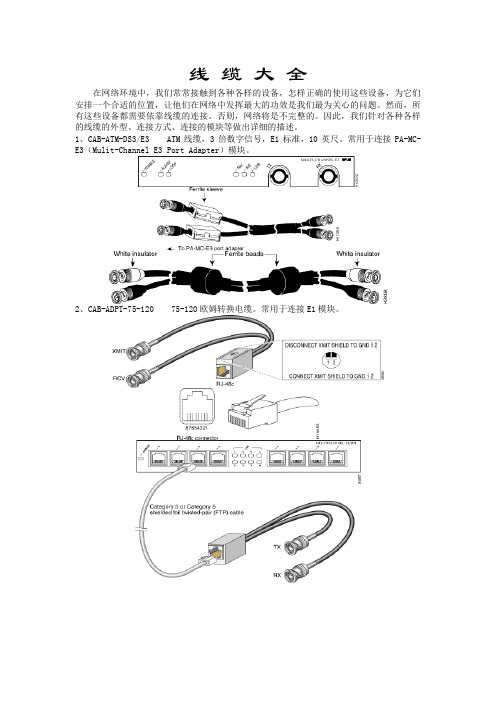
线缆大全在网络环境中,我们常常接触到各种各样的设备,怎样正确的使用这些设备,为它们安排一个合适的位置,让他们在网络中发挥最大的功效是我们最为关心的问题。
然而,所有这些设备都需要依靠线缆的连接。
否则,网络将是不完整的。
因此,我们针对各种各样的线缆的外型、连接方式、连接的模块等做出详细的描述。
1、CAB-ATM-DS3/E3ATM线缆,3倍数字信号,E1标准,10英尺。
常用于连接PA-MC-E3(Mulit-Channel E3 Port Adapter)模块。
2、CAB-ADPT-75-120 75-120欧姆转换电缆。
常用于连接E1模块。
3、CAB-ADPT4P-75-120 4个一组75-120欧姆转换电缆。
4、CAB-E1-PRI E1-ISDN 非平衡线缆,10英尺。
RJ-48C to RJ-48C5、CAB-E1-TWINAX E1 120欧姆平衡线缆,3米。
DB-15 to Twinax6、CAB-E1-BNC E1 75欧姆非平衡线缆,5米。
DB-15 to BNC7、CAB-E1-PRI/NT DB-15 to RJ-48C8、CAB-E1-DB15 DB15-DB15 NULL9、CAB-V35MT V.35线缆,DTE端,公头,10英尺。
10、CAB-V35FC V.35线缆,DCE端,母头,10英尺。
11、CAB-232MT RS-232线缆,DTE端,公头,10英尺。
12、CAB-232FC RS-232线缆,DCE端,母头,10英尺。
13、CAB-449MT RS-449线缆,DTE端,公头,10英尺。
14、CAB-449FC RS-449线缆,DCE端,母头,10英尺。
15、CAB-X21MT X.21线缆,DTE端,公头,10英尺。
16、CAB-X21FC X.21线缆,DCE端,母头,10英尺。
17、CAB-530MT RS-530线缆,DTE端,公头,10英尺。
18、CAB-OCT-V35-MT 1拖八V.35线缆, DTE端,公头,10英尺。
as3008 标准 -回复
as3008 标准-回复AS3008标准及其在电气设计中的应用AS3008标准是澳大利亚电气行业中广泛采用的一项标准,它规定了电气系统及设备设计、安装和维护的要求。
本文将逐步回答关于AS3008标准及其在电气设计中的应用的问题。
第一步:了解AS3008标准的基本概念和内容AS3008标准是澳大利亚标准协会(Standards Australia)制定的一项电气行业标准,其全称为《电气装置:电气安装——选择和安装电缆》。
该标准主要关注的是电缆的选择和安装,以确保电气系统的安全性和可靠性。
AS3008标准涵盖了电缆的尺寸、类型、敷设方式、负载能力、短路能力等方面的要求,以及用于计算负载和电缆选择的公式和图表。
第二步:了解AS3008标准的适用范围AS3008标准适用于各种电气系统和设备的设计、安装和维护,包括住宅、商业、工业和公共建筑等。
无论是新建还是改造项目,无论是高压还是低压系统,都应遵循AS3008标准的要求。
该标准旨在保护人身和财产安全,同时提高电气系统的效能和可靠性。
第三步:了解AS3008标准对电缆选择的要求AS3008标准规定了选用合适电缆的方法,包括考虑电压降、电缆容量、短路能力等因素。
在电缆选择时,还需要考虑环境因素,如温度、湿度和机械载荷等。
此外,该标准还涉及到对不同类型电缆的要求,如塑料绝缘电缆、橡胶绝缘电缆、裸露导线等。
第四步:了解AS3008标准对电缆敷设方式的要求AS3008标准规定了电缆敷设的不同方式,包括直埋敷设、架空敷设、埋地管道敷设等。
不同敷设方式需要考虑不同的因素,如绝缘材料、机械保护和外界干扰等。
该标准还明确了敷设电缆时的最小弯曲半径和最大张力等要求。
第五步:了解AS3008标准对电缆的标记和标识的要求AS3008标准要求对电缆进行标记和标识,以便于辨识和维护。
电缆标记需要包括电流等级、电压等级、短路能力等信息。
此外,对于特殊环境下使用的电缆,如火灾风险区域和化学腐蚀环境,还需要相应的标识和警示。
- 1、下载文档前请自行甄别文档内容的完整性,平台不提供额外的编辑、内容补充、找答案等附加服务。
- 2、"仅部分预览"的文档,不可在线预览部分如存在完整性等问题,可反馈申请退款(可完整预览的文档不适用该条件!)。
- 3、如文档侵犯您的权益,请联系客服反馈,我们会尽快为您处理(人工客服工作时间:9:00-18:30)。
The following standards represent most of the common cable design standards used in Australia and New Zealand. They cover cables that you are likely to see or use on a daily basis. General Cable has the capability to manufacture cables to a very broad range of international design specifications and standards, including special purpose constructions to meet customer specialist and specific needs.
Flat TPS:
AS/NZS 5000.2
This is the standard used for most General Cable Flat TPS products. It has been used for Australian products for several years and now applies to New Zealand products (which have recently changed from NZS 6401). The principal differences from NZS 6401 are
450/750V designation, higher temperature rated PVC (90° as opposed to 75°C) and the option to use XLPE and crosslinked PVC materials.
This standard is generally used for 1mm2 –
16mm2 products.
AS/NZS 5000.1
This standard replaces AS 3147, and covers Flat TPS cables rated to 600/1000V. These designs have a much thicker sheath (still rated to 90°C) than cables to the standards listed above and are generally used for cables above 25mm2.
Circular TPS / Multicore
NZS 6401
AS/NZS 5000.1
AS/NZS 5000.2
AS/NZS 5000.3
BS 6346
BS 5467
IEC 60502.1
There are many standards covering low voltage power distribution cables, but they all generally offer a similar cable in most respects. Some key points that users should be aware of are:
•NZS 6401 cables are expected to be phased out and replaced with equivalents to AS/NZS 5000.1, AS/NZS 5000.2 and
AS/NZS 5000.3 standards. •BS 5467and BS 6346 permit lower insulation radials on some conductors
below 10mm².
•IEC 60502.1 and AS/NZS 5000.1 have a calculated sheath radial based on the
diameter of the cable with minimum of
1.8mm for multicore cables; BS standards
use tabulated dimensions with a minimum of 1.4mm.
•Australasia have moved to white as a phase colour (to avoid possible confusion
with green/yellow earths), some BS
standards still allow a yellow phase
colour.
Neutral Screen:
AS/NZS 4961
This standard supersedes both NZS 6401 and AS/NZS 3155. Worth noting that in NZ a neutral screen cable with a 3.2mm sheath can be direct buried without further mechanical protection. This is not the case however in Australia.
Medium Voltage Cables: 1.9/3.3,
3.8/6.6, 6.35/11, 12.7/22, 19/33kV
AS/NZS 1429.1
BS 6622
IEC 60502.2
AS/NZS 1429.1 is the most commonly used standard in Australasia for XLPE cables, but there are only minor differences between the above three standards.
AS/NZS 1026
BS 6480
Paper Lead cables are a very well proven technology, and as such have not changed for many years. These two standards are
virtually interchangeable.
AS/NZS 4026
AS/NZS 4026 is a standard that was developed in Australia to standardise on a set of cables for use in underground residential distribution systems (URD). The set of cables is taken from AS/NS 1429.1, AS/NZS 1026 and AS/NZS 5000.1, and also includes a unique design called a “service” cable.
Standards Used in
Australia / NZ
men
General Cable Australia Pty Ltd。