Bachmann控制器使用说明
Bacharach MGS系列控制器说明书

1: ZONE ET CONDITIONS D'UTILISATIONLes contrôleurs série MGS de Bacharach donnent des indications d'état d'alarme local (par des voyants LED multicolores par canal) ainsi que des sorties d'alarme communes numériques à 1 ou 2 niveaux (par relais) en fonction de 1, 2, 4 ou 6 signaux d'entrée et de 1 ou 2 points de consigne définissables par l'utilisateur.Les contrôleurs MGS prennent en charge plusieurscapteurs/émetteurs d'entrée (1, 2, 4 ou 6 canaux) selon le modèle du contrôleur. Les entrées sont des signaux standard 4-20 mA provenant de capteurs série MGS ou de tout émetteur standard linéaire 4-20 mA.L'instrument est alimenté sous 100-230 VCA (50-60 Hz) ou 12 VCC (selon spécification à la commande).N° de réf. : 6709-9002Révision 025 janvier 20162: CONSIGNES DE SÉCURITÉMANUEL DE L'UTILISATEUR : Avant d'utiliser ce matériel, lisez attentivement et respectez scrupuleusement le Manuel de l'utilisateur (référence 6709-9000). L'utilisateur doit comprendre parfaitement et appliquerscrupuleusement les instructions. Utilisez le matériel uniquement aux fins décrites et dans les conditions précisées dans ces documents.RESPECT DU CODE : Conformez-vous à toutes les lois, règles et réglementations locales et nationales relatives à ce matériel.PIÈCES D'ORIGINE : Utilisez uniquement des pièces de rechange et des accessoires d'origine Bacharach, faute de quoi le bon fonctionnement du matériel pourrait être altéré.UTILISATION RÉSERVÉE AU TECHNICIEN : Cet appareil doit être installé par un technicien suffisamment qualifié qui pourra l'installer dans le respect des présentes instructions et des normes applicables dans le domaine ou le pays concerné. Les utilisateurs de l'appareil doivent connaître les règlements et normes de leur domaine et pays pour l'utilisation de cet appareil. Ces remarques ne sont qu'indicatives et le constructeur n'est aucunement responsable de l'installation ou de l'utilisation de cet appareil.Le non-respect des présentes instructions et des règles applicables dans le domaine pourl'installation et l'utilisation de l'appareil peuvent conduire à des blessures graves voire mortelles et le constructeur ne saurait en être tenu responsable.SÉCURITÉ DE MONTAGE : Ce contrôleur doit être raccordé par un interrupteur ou disjoncteur convenablement repéré, positionné de façon adéquate et facilement accessible pour le mettre hors tension.AVERTISSEMENT : Respectez scrupuleusement les instructions du Manuel du contrôleur(référence 6709-9000) disponible sur .ATTENTION : NE PAS MONTER lecontrôleur MGS dans un emplacement pouvant contenir des liquides ou des vapeurs inflammables. L'utilisation de tout équipement électrique dans un tel environnement met en danger la sécurité.Siège social mondial 621 Hunt Valley CircleNew Kensington, PA 15068, États-UnisTéléphone : 724-334-5000 • Télécopie : 724-334-5001Numéro gratuit (depuis les États-Unis d'Amérique) : 1-800-736-4666Site Web : Email:********************114A Georges Street Lower Dun Laoghaire • Co Dublin • IrlandeTéléphone : +353 1 284 6388 • Télécopie : +353 1 284 6389GUIDE D'INSTALLATION4: DIMENSIONS FACTEURS ENVIRONNEMENTAUX : Examinez soigneusement toute la gamme des conditions environnementales auxquelles seront exposés les appareils.APPLICATION : Il est nécessaire d'évaluer les détails spécifiques à l'application (p. ex. les fuites possibles, les courants ou le tirant d'air...).ACCESSIBILITÉ : Il convient de prévoir le niveau d'accessibilité nécessaire pour l'entretien.ACCESSOIRES : Il faut penser au type de matériel en option et d'accessoires qui seront utilisés avec le système.FACTEURS ÉLECTRONIQUES : Le systèmecontient des composants électroniques sensibles qui peuvent être facilement endommagés. Ne pas toucher ni perturber ces composants.Montez le contrôleur MGS en tenant compte des points ci-dessus, des dimensions du produit (voir Section 4) et des longueurs maximales de câblage (voir Section 5).3: MONTAGEBoîtier de contrôleur (1-2 canaux)VisBoîtier de contrôleur (4-6 canaux)5: CÂBLAGE1: Dénudez le fil sur 5 à 7 mm (0,2 à 0,25 po).2: Raccordez les fils comme indiqué.AVERTISSEMENT CONCERNANT LES FILS BLINDÉS : Raccordez le blindage des fils électriques à la terre du système de commande central (p. ex. le châssis, la barre-bus de terre...).AVERTISSEMENT : Le câble d'alimentation secteur doit être d'un type homologué en fonction des réglementations locales. Le raccordement à l'alimentation secteur doit s'effectuer par une fiche et une prise homologuées commutées et protégées par fusible facilement accessible (ou selon les règlements de câblage locaux), à moins de 3 m (10 pi) du capteur/émetteur.OUVERTURES POUR CÂBLES : Le boitier de contrôleur métallique dispose d'un certain nombre d'ouvertures PG7 pour presse-étoupes ou bouchons.REMARQUE : Après l'achèvement du câblage, remontez soigneusement l'enveloppe et ses composants.Veuillez consulter le Manuel de l'utilisateur(référence 6709-9000) sur pour obtenir des instructions détaillées sur l'accès aux composants internes pour le câblage.Consultez le manuel du contrôleur (référence 6709-9000) sur pour d'autres configurations de câblage.CONTRÔLEUR MGSAssurez-vous que les raccordements1 à 4 de chaque capteurcorrespondent bien aux numéros indiqués sur le bornier de l'alarmeprincipale, sinon le système pourrait mal fonctionner et être endommagé.Assurez-vous que les raccordements1 à 4 de chaque capteurcorrespondent bien aux numérosindiqués sur le bornier de l'alarmeprincipale, sinon le système pourrait mal fonctionner et être endommagé.Configuration 2 capteurs 1 alarmeConfiguration 2 capteurs 2 alarmeConfiguration 6 capteurs 1 alarme。
美国贝克曼生化分析仪简单操作规程
美国贝克曼生化分析仪简单操作规程(适合CX系列):1编辑样本工作表:主屏幕---F1SAMPLE PROGRAM---F1 PROGRAM SECTOR----输入架子号---回车---选择实验项目---F7NEXT SECTOR或F8 NEXT CUP继续输入--- 输入完毕---按PRV SCREEN键返回2样本复查:主屏幕---F1 SAMPLE PROGRAM---F4 SAMPLE RERUN---输入架号、杯号---选择复查项目---按PRV SCREEN键返回3查看样本盤盘状态主屏幕---F6 CAROUSE STATUS---查看样品检测状态(以不同颜色表示完成、未完成、不能完成)4批量输入主屏幕---F1 SAMPLE PROGRAM---F2 PROGRAM BATCH---输入杯架号(连续的用…-‟连接,不连续的用逗号隔开)---回车---输入总的样本数(小于7倍杯架数)---回车---选择实验项目---F7 NEXT SECTOR或F8 NEXT CUP---回主屏幕5清除整个杯架主屏幕---F1 SAMPLE PROGRAM---F5 CLEAR SECTOR---输入杯架号(连续的用…-‟连接,不连续的用逗号隔开)---回车---输入…y‟---回主屏幕6查看各个杯架项目主屏幕---F1 SAMPLE PROGRAM---F3 LOAD LIST---输入杯架号---回车---PAGE DOWN/UP翻看---回主屏幕7打印设置主屏幕---F4 SPECIAL FUNCTIONS---输入…4‟---回车---输入…5‟---回车---F3 PRINT OPTION---输入…1可打‟或…2不可打‟---回车---回主屏幕8单位选择主屏幕---F4 SPECIAL FUNCTIONS---输入…4‟---回车---输入…7‟---回车---将光标移到目标项目处用SELECT重复选择直到正确的单位---回主屏幕9结果查看主屏幕---F4 SPECIAL FUNCTIONS---输入…2‟---回车---输入查询条件---回车---输入号码---回车---选择输出形式---回车10参数设置①进入参数界面主屏幕---F4 SPECIAL FUNCTIONS---输入…5‟---回车---F1 DEFINE/REVIEW---输入项目号---回车---输入具体参数(两页)---回主屏幕②新项目的登陆主屏幕---F4 SPECIAL FUNCTIONS---输入…4‟---回车---选择一个位置输入新项目名称③具体参数TEST NAME:最多输入4位REACTION TYPE:ENDPOINT1、RATE1、ENDPOINT2、RATE2(1代表没减试剂空白,2代表减掉了试剂空白)UNITS:单位(SELECT重复按选择)DECIMAL PRECISION:小数位(SELECT重复按选择)REACTION DIRECTION:反应方向(SELECT重复按选择)CALCULATION FATOR:计算因数MATH MODEL:拟合方式(LINEAR线性拟合,MA TH MODEL1四参数Log-logit,MATH MODEL2五参数Logit,MATH MODEL3五参数指数拟合)NUMBER OF CALIBRATORS:校准液个数(0-6,输0时必须输入因数,并输入相应浓度)包括空白CALIBRTORS V ALUES:CALIBRATION TIME LIMIT:校准时限(0.0-336.0,一般输入336.0)WA VELENGTH(PRIMARY AND SECONDARY):主副波长PRIMARY INJECT REAGENT1:第一试剂(A或B)VOLUME:加入体积(125-327)PRIMARY INJECT REAGENT2:第二试剂(NONE、A、B或C)ADD TIME:试剂二加入时间(自己设定)SAMPLE VOLUME:样品加入体积(其固定加入时间为330秒时)REAGENT BLANK:试剂空白读点时间(以R1为零时)REACTION:反应读点时间(以R2为起始点)USABLE RANGE:线性范围ERROR DETECTION LIMITS:错误限制(一般都设为-1.500到1.500)SUBSTRATE DEPLETION:底物消耗INITIAL RATE:一般正反应设为99.999负反应设为-99.999DELTA ABS:一般设为1.500④清除参数主屏幕---F4 SPECIAL FUNCTIONS---输入…5‟---回车---F1 DEFINE/REVIEW---F3 CLEAR CHEMISTRY---输入要清除的号码---回车---输入…y‟---回主屏幕11试剂登陆1) 卸掉要调整参数的试剂主屏幕---F2 REAGENT LOAD---按选择键选定试剂名select键选择---F2 MANUAL LOAD---输入…3‟---回车---回到主屏幕2) 装载上试剂主屏幕---F2 REAGENT LOAD---选择到刚卸载的试剂位置select键选择---F2 MANUAL LOAD---输入…2‟---回车---输入项目名称---回车---打开试剂舱盖把试剂装入---关闭舱盖---F1CONTINUE---等仪器检查完以后回到主屏幕12定标设置主屏幕---F3 CAL---移动光标导要进行定标的项目用SELECT键选择F1 CAL CUP ASSFNMNT---输入可用的杯架号---回车---F2 CAL LOAD LIST---按照仪器的提示显示顺序装定标液----回到主屏幕---按“开始”开机12检查试剂状况主屏幕---F2 REAGENT LOAD---F5 REAGENT STATUS---PAGE UP/DOWN---回主屏幕13关机主屏幕---IDLE---F4---等仪器左上角出现“Please Wait….”消失后---关主电源14清洗灌注主屏幕---F4---1回车---选择所须灌注项目---F1等仪器工作完后回到主屏幕15查看仪器状态主屏幕---F8---F7---有红色的表示此处异常---回主屏幕16查看比色情况主屏幕---F8---F6---按-PAGE UP/DOWN查看结果---回主屏幕17急诊标本输入主屏幕---F1---F1---选择架子号---回车---选择项目---F7---回到主屏幕不同的型号、不同版本的软件操作可能有些微的差别,请注意区别,操作都大同小异。
赫兹曼控制器 说明书v1_2
iFLEX C3控制器使用说明书使用说明书V1.0徐州赫思曼电子有限公司2010年12月版本记录时间编写人员校对人员版本信息说明2008-1 郑达标杨玉杰V1.0 初始版本2009-3 杨玉杰V1.1 增加PLC browser功能参数管理器更改扩展板功能2010-12 杨玉杰V1.2 更改端口配置表增加I/O跳线板说明增加IIC_MEMORY_PAGE_WRITE函数增加IIC_MEMORY_PAGE_READ函数更改电流反馈A/D转换值和实际电流值对应关系目录1 硬件介绍.....................................................- 3 - 1.1 功能模块. (3)1.2 输入输出端口分配 (5)1.3 端口技术参数 (6)1.3.1 电源接口..............................................- 6 -1.3.2 通信接口..............................................- 7 -1.3.3 PWM输出/开关量输出/开关量输入接口.....................- 7 -1.3.4 开关量输出/开关量输入接口.............................- 8 -1.3.5 集电极开路开关量输出/计数器输入接口/电流反馈输入......- 8 -1.3.6 模拟量输入接口........................................- 9 -1.3.7 RS232接口............................................- 10 -1.3.8 扩展板.............................................- 11 -2 IFLEX C3模拟盒.............................................- 17 -3 系统软件介绍................................................- 19 - 3.1概述.. (19)3.2 软件安装 (19)3.2.1CoDeSys软件安装......................................- 19 -3.2.2 Target安装..........................................- 24 - 3.3 C O D E S YS软件介绍 (27)3.3.1 程序结构.............................................- 27 -3.3.2 变量声明.............................................- 29 -3.3.3 数据类型.............................................- 31 -3.3.4 库函数管理...........................................- 32 -3.3.5 PLC Browser..........................................- 36 -3.3.6 Target设置...........................................- 40 -3.3.7 Parameter manager....................................- 45 -3.3.8 PLC Configuration....................................- 48 - 3.4 编写一个小程序 (51)3.4.1控制灯的闪烁.........................................- 51 - 3.5 C O D E S YS 在线调试.. (58)3.5.1 Login................................................- 58 -3.5.3 Run..................................................- 59 -3.5.4 Stop.................................................- 59 -3.5.4 Reset 和 Reset(Cold).................................- 59 -3.5.5 Reset (Original)....................................- 59 -3.5.6 Toggle breakpoint....................................- 59 -3.5.7 Step in,Step over....................................- 59 -3.5.8 Write value,Force value,Release force................- 60 -3.5.9 Create boot project..................................- 60 -3.5.10 Write file to PLC..................................- 62 - 3.6 CAN设备配置 (63)3.7.1添加一个支持CAN2.0A通讯协议的设备...................- 63 -3.7.2添加一个支持CAN2.0B 通讯协议的设备...................- 65 -3.7.3 配置CAN设备.........................................- 65 -3.7.4 通过Codesys 代码实现CAN 数据的收发..................- 69 - 3.7 I CAN6T OOL 介绍. (47)3.5.1上传HEX格式文件至控制器.............................- 47 -3.5.2 将HEX格式文件转换为二进制文件.......................- 50 -3.5.3 读入控制器FLASH中指定地址的内容,以16进制格式显示..- 51 -3.5.4校验上传的HEX文件是否正确...........................- 52 -3.5.5控制器FLASH存储器擦除...............................- 53 -3.5.6 参数管理器...........................................- 55 -4 附录........................................................- 58 -A I CAN6E XT L IB.LIB库介绍 (58)B I FLEX C3外形尺寸图 (73)1硬件介绍iFlexC3是一款适用于工程机械控制的可编程控制器,设计可靠,具有多种标准电气接口,可根据应用需求进行灵活配置。
bachmann操作手册翻译

与M1的控制系统,简单到复杂的控制系统可以放在一起。
此外,终端可以集成在系统和多个控制器可以通过一个控制中心联网。
下图示意性地示出的M1控制系统各部件之间的连接。
图2:M1控制系统原理图工具M1控制器一个M1控制器自主工作。
如果多个M1控制器在同一网络中,他们可以互相交流。
开发的PC开发计算机用于控制器的配置和调试开发上位机与控制器通过网络进行通信。
.终点站终端和巴赫曼电子工业电脑用于呈现信息和应用和操作机器。
该连接是由一个控制器或通过在网络中的集成。
进一步的信息:硬件〔产品说明〕> 15章"操作和观察装置〔可视化〕"单独的终单独的终端手册端手册控制站控制站是用于监视从一个中央位置的多个控制器。
先决条个人电脑和控制器之间的网络通信必须是可能的件:控制站电脑必须设置适当的软件网络> 4章"控制室联网"2M-BASE V3.91M1 control system2 Hardware structure本章提供了一个概述的各个组成部分,与控制系统可以放在一起。
个别组件的详细描述:--- 硬件〔产品说明〕背板背板用于安装单独的模块和处理器模块与其他模块之间的通信。
电源单元电源或电源模块提供硬件模块通过背板的电源。
每个背板需要电源模块。
这可以是一个自治的模块〔如nt255〕或集成电源模块〔如bes212 / N〕。
处理器模块控制器有一个处理器模块。
通过处理器模块的完整的通信和配置的控制器发生。
处理器模块的软件结构:M1控制系统> 3章"软件结构"输入/输出模块传感器或执行器与输入/输出模块连接到控制器。
总线模块对于分布式控制系统,主站和从站通过总线系统联网。
具体的模块,必须的使用取决于总线系统使用。
M1控制系统>第2.2.2"分布式控制系统"特殊模块在M1控制系统、专用模块可用于特定的应用程序。
实例:网格测量〔gmp2xx〕振动测量〔aic212〕温度测量〔ti214〕2.2不同的应用程序的变种,可根据控制系统的复杂性和应用程序。
慧能控制系统 BACnet Modbus 和 LonWorks 转换器附件说明书

Manufacturer reserves the right to discontinue, or change at any time, specifications or designs without notice and without incurring obligations.Catalog No. 04-53300217-01Printed in U.S.A.Form 30XV-16SI Pg 1 7-19Replaces: 30XV-12SIInstallation InstructionsPart No. 30XV70001701 (BACnet/Modbus)Part No. 30XV70001901 (LonWorks)SAFETY CONSIDERATIONS . . . . . . . . . . . . . . . . . . .1INTRODUCTION . . . . . . . . . . . . . . . . . . . . . . . . . . . . . .1INSTALLATION . . . . . . . . . . . . . . . . . . . . . . . . . . . . . .3Preliminary Steps . . . . . . . . . . . . . . . . . . . . . . . . . . . .3BACnet/Modbus Translator . . . . . . . . . . . . . . . . . . . .3LonWorks Translator . . . . . . . . . . . . . . . . . . . . . . . . .4SAFETY CONSIDERATIONSInstallation of this accessory can be hazardous due to electrical components and equipment location (such as a roof or elevated structure).Only trained, qualified installers and service technicians should in-stall and service this equipment.When installing this accessory, observe precautions in the litera-ture and on labels attached to the equipment, as well as other safe-ty precautions that may apply.•Follow all safety codes.•Wear safety glasses and work gloves.•Use care when handling and installing this accessory.•Follow proper Lockout/Tagout procedures.INTRODUCTIONThe Carrier CCN BACnet/Modbus Translator Accessory module with RS-485 communication, shown in Fig. 1, is a micro-controller-based module that provides the ability to easily interface Carrier CCN controllers to third party non-Carrier control equipment. The BACnet/Modbus Carrier Translator provides CCN to Modbus Remote Terminal Unit (RTU) and BACnet Master-Slave Twisted-Pair (MS/TP)protocol conversion. See Table 1 for the contents of the Carrier CCN BACnet/Modbus Translator accessory package. The LonWorks Carrier Translator Accessory module with LON FT-10A communication, shown in Fig. 2, is a micro-controller-based module that provides the ability to easily interface Carrier CCN controllers to third party non-Carrier control equipment. The LonWorks Carrier Translator provides CCN to LonWorks FT-10A ANSI/EIA-709.1 protocol conversion. See Table 2 for the contents of the Carrier CCN LonWorks Translator accessory package.The 30XV units accept one Carrier CCN BACnet/Modbus or LonWorks Translator accessory. The accessory kit provides all necessary wires and hardware for accessory installation.WARNINGElectrical shock can cause personal injury and death. Shut off all power to this equipment during installation. There may be more than one disconnect switch. Tag all disconnect locations to alert others not to restore power until work is completed.Table 1 — Accessory Package Contents (30XV70001701)ITEM #ITEMUNIT USAGEP/NQTY 1BACnet/Modbus Translator ModuleAll 30XV5012240112SCREW All AC41AA08643SCREW All AL56AU12844WIRE TIE AllHY76TB11045BRACKET350-500 (30XVA/XVB)30XV5010320116HARNESS ASSY 140-325 (30XVA), 350-500 (30XVA/XVB)30XV50103101 (30XVHLAACL-A00)17HARNESS ASSY 140-325 (30XVB)30XV50119801 (30XVHVAAFL-A00)18INSTRUCTIONSAll30XV-16SI130XV140-500BACnet*/Modbus † and LonWorks**Translator Accessories* BACnet is a registered trademark of ASHRAE (American Society of Heating, Refrigerating and Air-conditioning Engineers).† Modbus is a registered trademark of Schneider Electric.** LonWorks is a registered trademark of Echelon Corporation.Fig. 1 — BACnet/Modbus Translator ModuleFig. 2 — LonWorks Translator ModuleTable 2 — Accessory Package Contents (30XV70001901)ITEM #ITEMUNIT USAGEP/NQTY 1LON Translator ModuleAll 30XV50122501 12SCREW All AC41AA08643SCREW All AL56AU12844WIRE TIE AllHY76TB11045BRACKET 350-500 (30XVA/XVB)30XV5010320116HARNESS ASSY 140-325 (30XVA),350-500 (30XVA/XVB)30XV50103101 (30XVHLAACL-A00)17HARNESS ASSY 140-325 (30XVB)30XV50119801 (30XVHVAAFL-A00)18INSTRUCTIONSAll30XV-16SI1INSTALLATIONPreliminary StepsFollow these steps for either the BACnet/Modbus or LonWorks Translator:1.Inspect package contents for missing or damaged parts. File aclaim with the shipping agency if parts are damaged, and notify your Carrier representative if any item is missing.2.Open and tag all electrical disconnects in accordance withproper Lockout/Tagout procedures.3.Open the unit control box door.4.Install the CCN Carrier Translator module in the locationshown in Fig. 3, 4 or 5 by using screws (item #2). For unit sizes 350-500 tons (Fig. 5) a bracket (item #5) must be installed first using screws (item #3) and then mounting CCN Carrier Translator module to the bracket.5.Proceed to the steps outlined in the “BACnet/Modbus Trans-lator” section on this page or the “LonWorks Translator” sec-tion on page 4 as appropriate.Fig. 3 — Translator Module Installation Location for30XVA140-325Fig. 4 — Translator Module Installation Location for30XVB140-325Fig. 5 — Translator Module Installation Location for30XV350-500BACnet/Modbus Translatorplete the procedure outlined in the previous “Preliminary Steps” section.2.Referring to Fig. 6, for 30XVB 140-325 locate wire har-ness (P/N 3050119801, item #7), for 30XVA 140-325and 30XVA/XVB 350-500 locate wire harness (P/N 30XV50103101, item #6) in the accessory kit.3.Connect the red wire labeled TB4-3 to an open connection point on terminal block TB4-3.4.Connect the other end of the red wire labeled LON/BAC J1-24V AC to the J1-1 terminal on the BACnet/Modbus Transla-tor board.5.Connect the brown wire labeled TB11-X2 to an open connec-tion point on terminal block TB11-X2.6.Connect the other end of the brown wire labeled LON/BAC J1-GND to the J1-2 terminal on the BACnet/Modbus Trans-lator board.7.Referring to Fig. 6, connect black wire labeled LON/BAC J2– to the terminal marked J2– on the BACnet/Modbus Translator board.8.Connect the white wire labeled LON/BAC J2 G to the termi-nal marked J2 G on the BACnet/Modbus Translator board.9.Connect red wire labeled LON/BAC J2+ to the terminal marked J2+ on the BACnet/Modbus Translator board.10.Connect the other end of the cable which has a 3-position plug and is labeled TB3 into the CCN connection on TB3located as shown in Fig. 3 for 30XV A 140-325, Fig. 4 for 30XVB 140-325 and Fig. 5 for 30XV A/XVB 350-500.11.Ensure that electrical connections are tight, and restore power to the unit.12.With power restored to the unit, the BACnet/Modbus Trans-lator board has three LEDs that are used to indicate opera-tional status. Refer to Table 3 for a description of each LED and what it indicates. For specific setup/configuration and table of points refer to the 30XV Start-up and Troubleshoot-ing guides.13.Remove tags from disconnects and close the control box door.33TORCARDTB4TB11LATORTB4TB11Manufacturer reserves the right to discontinue, or change at any time, specifications or designs without notice and without incurring obligations.Catalog No. 04-53300217-01Printed in U.S.A.Form 30XV-16SI Pg 4 7-19Replaces: 30XV-12SI© Carrier Corporation 2018Fig. 6 — BACnet/Modbus Translator ModuleWiring DiagramLonWorks Translatorplete the procedure outlined in the “Preliminary Steps”section on page 3.2.Referring to Fig. 7, 30XVB 140-325 locate wire harness (P/N 3050119801, item #7) or for 30XV A 140-325and 30XV A/XVB 350-500 locate wire harness (P/N 30XV50103101, item #6) in the accessory kit.3.Connect the red wire labeled TB4-3 to an open connection point on terminal block TB4-3.4.Connect the other end of the red wire labeled LON/BAC J1-24V AC to the J1-1 terminal on the LonWorks Translator board.5.Connect the brown wire labeled TB11-X2 to an open connec-tion point on terminal block TB11-X2.6.Connect the other end of the brown wire labeled LON/BAC J1-GND to the J1-2 terminal on the LonWorks Translator board.7.Referring to Fig. 7, connect black wire labeled LON/BAC J2– to the terminal marked J2– on the LonWorks Translator board.8.Connect the white wire labeled LON/BAC J2 G to the termi-nal marked J2 G on the LonWorks Translator board.9.Connect red wire labeled LON/BAC J2+ to the terminal marked J2+ on the LonWorks Translator board.10.Connect the other end of the cable which has a 3-positionplug and is labeled TB3 into the CCN connection on TB3located as shown in Fig. 3 for 30XV A 140-325, Fig. 4 for 30XVB 140-325 and Fig. 5 for 30XV A/XVB 350-500.11.Ensure that electrical connections are tight, and restore powerto the unit.12.With power restored to the unit, the LonWorks Translatorboard has three LEDs that are used to indicate operational sta-tus. Refer to Table 4 for a description of each LED and what it indicates. For specific setup/configuration and table of points refer to the 30XV Start-up and Troubleshooting guides.13.Remove tags from disconnects and close the control boxdoor.The LonWorks Carrier Translator’s default CCN address is 0,200(bus number, system element number). The default CCN baud rate is 9600 bps.Each LonWorks Carrier Translator has a unique LON address.The LON address can be sent to LON configuration tools when the LON Service Pin is pressed. See Fig. 2 for location of the LON Service Pin.Fig. 7 — LonWorks Translator ModuleWiring DiagramWire to third p a rty Mod bus or BACnet M S /TP comm u nic a tion networkTB 330XV50103101Wire to third p a rty LonWork s M S /TP comm u nic a tion networkTB 330XV50122501Table 3 — BACnet/Modbus Translator LED IndicatorsLED COLORINDICATESStatus Red Operating, initialization and configuration status. The LED blinks at a 2 Hz rate when initializing and at 1 Hz when operating correctly.CCN Yellow The Carrier Translator is sending CCN communication messages to the connected CCN controller. If the connected CCN controller is responding, its CCN LED will blink when a message is sent back to the Carrier Translator.RS-485GreenThe Carrier Translator is sending RS-485 communication messages to the Modbus or BACnet MS/TP network.Table 4 — LonWorks Translator LED IndicatorsLED COLORINDICATESStatus Red Operating, initialization and configuration status. The LED blinks at a 2 Hz rate when initializing and at 1 Hz when operating correctly.CCN Yellow The Carrier Translator is sending CCN communication messages to the connected CCN controller. If the connected CCN controller is responding, its CCN LED will blink when a message is sent back to the Carrier Translator.LONGreenThe Carrier Translator is sending LON communication messages to the third party LonWorks network.。
德国海因茨曼速度控制器操作说明
德国海因茨曼速度控制器操作说明德国海因茨曼速度控制器操作说明1、引言1.1 目的1.2 适用范围1.3 定义和缩写2、产品概述2.1 产品描述2.2 技术参数2.3 主要特点3、安全指南3.1 安全警告3.2 安装环境3.3 安全操作规范4、设备安装4.1 硬件安装4.1.1 工具准备4.1.2 安装步骤4.2 电气连接4.2.1 电路图4.2.2 连接步骤5、软件设置5.1 驱动程序安装5.2 参数设置5.2.1 变频机构设置 5.2.2 控制器参数设置5.3 运行测试6、操作说明6.1 启动和停止控制器6.2 设置速度6.3 调整加速度和减速度6.4 转向控制7、故障诊断和维修7.1 故障代码解析7.2 常见故障及解决方法7.3 维修注意事项8、计划维护8.1 定期检查8.2 维护记录9、附件9.1 使用手册9.2 产品图片9.3 电路图10、法律名词及注释- 法律名词1:解释说明 - 法律名词2:解释说明附.1 使用手册附.2 产品图片附.3 电路图附注:1、本文所涉及的法律名词及注释仅作参考,具体解释以实际法律条文为准。
2、本文涉及的附件如有更新,可在公司官网最新版本。
3、如有疑问或需要进一步说明,请联系海因茨曼公司客服部门。
该文档为德国海因茨曼速度控制器操作说明,详细说明了产品的概述、安装、设置、操作、故障诊断和维修等内容。
同时,附有使用手册、产品图片和电路图等附件供参考。
附注:1、本文涉及的法律名词及注释仅作参考,具体解释以实际法律条文为准。
2、本文涉及的附件如有更新,可在公司官网最新版本。
Bachmann软件使用
SL1500-LVRT风机测试作业指导书编制:审核:批准:日期:2009-08-20目录1. 安全规程 (3)1.1个从保护装置 (3)1.2 安全说明 (3)1.2.1断开所有的电源和电杆 (3)1.2.2 防止无意重新送电的安全措施 (4)1.2.3 核实电源的安全隔离 (4)1.2.4 接地和短路 (4)1.2.5.罩住临近的带电部件,封闭危险区域 (4)1.3 警告 (4)2.调前准备 (4)2.1调前工具器件准备 (4)2.2.检查风机的完整性 (5)2.3打开调试所需接线盒 (5)2.4更改习惯性错误线路 (6)3.上电前的绝缘和屏蔽接地检查 (7)3.1屏蔽检查 (7)3.1.1检测方法 (7)3.1.2 检测点 (7)3.1.3重要测量点 (8)3.2接地检测 (8)3.2.1需接地部分 (8)3.2.2非接地部分 (9)3.3绝缘检测 (9)4.上电后检查事项 (10)4.1检测电压、相序 (10)4.1.1电压的测量方法 (10)4.1.2相序的测量方法 (10)4.2上电及元件检查 (11)4.2.1利用发光二极管显示检查的器件 (11)4.2.2急停按钮检查 (11)5.PLC程序下载 (12)5.1使用FLASH卡分配地址设置通讯.................................................... 错误!未定义书签。
5.2使用PC分配地址设置通讯 (20)5.2.1TCP/IP通讯设置.................................................................... 错误!未定义书签。
5.2.2CAN通讯设置.......................................................................... 错误!未定义书签。
5.3下载程序............................................................................................ 错误!未定义书签。
Bachmann控制系统操作手册简版FD70-77-82-87-89

Bachmann控制系统操作手册成都阜特科技有限公司Chengdu Forward Technology Ltd.中国四川成都市高新区(西区)西区大道199号模具工业园C1栋Add:Building C1,Molding Tool Industry Park,No.199,Xiqu Road,ChengDu Hi-tech Zone, 611743P.R.ChinaTel:+862887988515Fax:+862887988512FA001-FD风力发电机组控制系统可适用于FD70/77/82/87/89,额定功率为1500kW的大功率风力发电机组。
风力发电机组的正常、高效运行直接关系到风场发电的经济效益。
人机操作界面为风力发电机组正常运行,日常维护提供了安全、稳定、快速、方便的实时监控操作平台。
2.1登陆&注销图2-1人机界面成功启动后即进入用户登陆界面(图2-1),输入正确的用户等级和密码获得相应权限即可进入主页。
登陆成功后进入人机操作界面,不同用户级别可进行不同权限的操作。
管理人员:登陆人机界面,可查看风力发电机组实时信息,也可进入手动操作界面,不能查看风力发电机组的运行设置参数等;维护人员:不但可以查看到风力发电机组的实时信息,对风力发电机组内的设备进行手动操作与调试,而且可以对机组运行参数进行修改。
登陆成功后,若需要退出请点击左上角的按钮,则会转入起始界面。
虚拟键盘:点击输入框即可弹出虚拟键盘如下图键盘按键包括“A-Z,a-z,0-9,←(删除),回车(确认输入)Clr(清除所有),Del(删除后面的字符),Esc(退出),SPC(包括键盘上所有字符……等和一些特殊字符)。
默认主要显示大写字母;选择a-z主要显示小写字母;选择0-9主要显示数字。
输入完密码后点回车获得相应权限,权限够了便能进入主页。
虚拟键盘如下图(图2-2):图2-22.2人机界面结构人机操作界面主工作区按功能有系统、维护、设置、报警4个部分。
Bacharach MGS Series 控制器用户手册说明书

1: OPERATING AREA AND CONDITIONSThe Bacharach MGS Series controllers provide local alarm status indications (via multi-colored, per-channel LEDs) as well as common single-level or dual-level digital (relay) alarm outputs based on 1, 2, 4, or 6 input signals and 1 or 2 user-definable set-points.MGS Controllers support multiple input sensors/ transmitters (1, 2, 4, or 6 channels) based on the model of the controller. Inputs are standard 4-20 mA signals from MGS-series sensors or any standard, linear, 4-20 mA transmitter.The instrument is powered 100V-230V AC (50-60Hz) or 12V DC (specified at time of order).P/N: 6709-9002Revision 0January 25, 20162: SAFETY INSTRUCTIONSUSER MANUAL: Before using this equipment, carefully read and strictly follow the User Manual (part number 6709-9000). The user must fully understand and strictly observe the instructions. Use the equipment only for the purposes listed and under the conditions speci-fied in those documents.CODE COMPLIANCE: Comply with all local and national laws, rules and regulations associated with this equipment.GENUINE PARTS: Use only genuine Bacharach spare parts and accessories, otherwise proper functioning of the equipment may be impaired.TECHNICIAN USE ONLY: This unit must beinstalled by a suitably qualified technician who will install this unit in accordance with these instructions and the standards in their particular industry/country. Operators of the unit should be aware of the regulations and standards in their industry/country for the operation of this unit. These notes are only intended as a guide and the manufacturer bears no responsibility for the installation or operation of this unit.Failure to install and operate the unit in accor -dance with these instructions and with industry guidelines may cause serious injury including death and the manufacturer will not be held responsible in this regard.SAFE MOUNTING: This controller must be connected by a marked, suitably located and easily reached switch or circuit-breaker as means of disconnection.WARNING: Strictly follow the instruc-tions in the Controller Manual (part number 6709-9000) available at .CAUTION: DO NOT MOUNT the MGS Controller in an area that may contain flammable liquids or vapors. Opera-tion of electrical equipment in such an area constitutes a safety hazard.World Headquarters 621 Hunt Valley CircleNew Kensington, PA 15068 USAPhone: 724-334-5000 • Fax: 724-334-5001Toll Free: 1-800-736-4666Website: E-mail:********************114A Georges Street Lower Dun Laoghaire • Co Dublin • IrelandPhone: +353 1 284 6388 • Fax: +353 1 284 6389INSTALLATION GUIDE4: DIMENSIONSENVIRONMENTAL CONSIDERATIONS: Care -fully consider the full range of environmental conditions to which the instruments will be exposed.APPLICATION CONSIDERATIONS: The specifics of the application (for example, possible leaks, air movement/draft, etc.) must be observed.ACCESSIBILITY CONSIDERATIONS: The degree of accessibility required for maintenance purposes must be granted.ACCESSORY CONSIDERATIONS: The types of optional and accessory equipment that will be used with the system must be kept in mind.ELECTRONIC CONSIDERATIONS: The system contains sensitive electronic components that can be easily damaged. Do not touch nor disturb any of these components.Mount the MGS Controller according to the above considerations, product dimensions (see Section 4), and the maximum wiring lengths (see Section 5).3: MOUNTINGController Housing (1-2 Channels)ScrewController Housing (4-6 Channels)5: WIRING1: Strip 0.2 to 0.25 inches (5 to 7 mm) of wiring insulation.2: Connect the wires as indicated.SHIELD WIRE WARNING: Connect the shield of the power wires to the earth ground of the central control system (e.g., chassis, ground bus bar, etc.).WARNING: The mains power supply cable should be of an approved type based on local regulations. Connection to the mains power supply must be made via an approved, readily-accessible, switched and fused plug and socket (or as per local wiring regula-tions) which should be within 19 feet (3 meters) of the sesnor/transmitter.CABLE OPENINGS: The metal controller housing provides a number of PG7 openings for cable glands or plugs.NOTE: After wiring is completed,carefully re-assemble the enclosure and its components.Refer to the User Manual (part number 6709-9000) at for detailedinstructions on accessing the internal components for wiring.Refer to the Controller manual (part number 6709-9000) at for additional wiring configurations.Ensure that connections 1 to 4on each sensor connect to their corresponding numbers on theterminal block in the main alarm unit, otherwise the system will not function correctly and could bedamaged.Ensure that connections 1 to 4on each sensor connect to their corresponding numbers on theterminal block in the mainalarm unit, otherwise the system will not function correctly and could bedamaged.2 Sensor 1 Alarm Confirguration2 Sensor 2 Alarm Confirguration6 Sensor 1 Alarm Confirguration。
Bachmann控制器使用说明
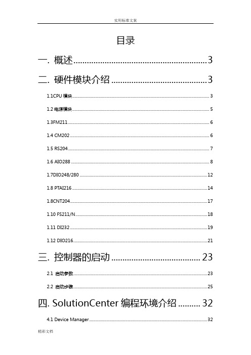
目录一. 概述 (3)二. 硬件模块介绍 (3)1.1CPU模块 (3)1.2电源模块 (5)1.3FM211 (6)1.4 CM202 (6)1.5 RS204 (7)1.6 AIO288 (8)1.7DIO248/280 (12)1.8 PTAI216 (14)1.8CNT204 (17)1.10 FS211/N (18)1.11 DI232 (19)1.12 DIO216 (21)三. 控制器的启动 (23)2.1 启动参数 (23)2.2 启动步骤 (25)四. SolutionCenter编程环境介绍 (32)4.1 Device Manager (32)Bachmann 控制器使用说明书一. 概述巴赫曼控制器是一个来自奥地利的工业自动化控制设备,被称为风机专用控制器。
它运行基于Vxworks的实时操作系统,支持多任务,具有强大的内存管理、界面编程等功能。
巴赫曼公司提供的SolutionCenter软件,是支持巴赫曼控制器的编译环境。
通过此软件可以使用C/C++编程并且生成可执行文件下载到控制器运行;或者是查看控制器的配置信息、以及控制器内运行的程序信息等;还可通过自带的java编译环境,编写与控制器关联的界面程序。
二. 硬件模块介绍1.1CPU模块指示灯:RUN灯亮时(绿色):控制器在Run模式下运行良好INT灯亮时(黄色):系统正在初始化ERR灯亮时(红色):控制器重启/运行错误INT和ERR等同时亮时(黄色,红色):系统运行在test模式下拨码:MPC240有两个拨码盘,下面的是高位,上面的是低位。
高位的拨码盘决定控制器运行模式,当高位拨码盘打到0~D之间,控制器运行在RUN模式;当高位拨码盘打到E,控制器运行在TEST模式;当高位拨码盘打到E,控制器运行在PROG模式。
三种模式区别:PROG模式:用来对控制器中PC卡进行编程,此时从flash0启动。
(一般不使用)TEST模式:用来对控制器进行调试,一般用来修改控制器IP和启动路径。
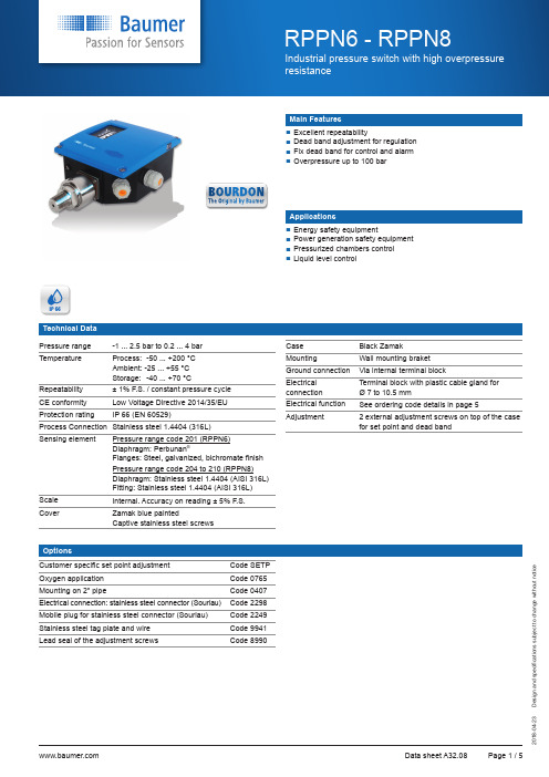
Baumer RPPN6-RPPN8 工业压力开关说明书
s i g n a n d s p e c i fi c a t i o n s s u b j e c t t o c h a n g e w i t h o u t n o t i c eMain FeaturesApplicationsExcellent repeatability D ead band adjustment for regulation F ix dead band for control and alarm Overpressure up to 100 barEnergy safety equipment Power generation safety equipment Pressurized chambers control Liquid level controlTechnical Data Pressure range -1 ... 2.5 bar to 0.2 ... 4 bar TemperatureProcess: -50 ... +200 °CAmbient: -25 ... +55 °C Storage: -40 ... +70 °CRepeatability ± 1% F.S. / constant pressure cycle CE conformity Low Voltage Directive 2014/35/EU Protection rating IP 66 (EN 60529)Process Connection Stainless steel 1.4404 (316L)Sensing elementPressure range code 201 (RPPN6)Diaphragm: Perbunan ®Flanges: Steel, galvanized, bichromate finish Pressure range code 204 to 210 (RPPN8)Diaphragm: Stainless steel 1.4404 (AISI 316L)Fitting: Stainless steel 1.4404 (AISI 316L)Scale Internal. Accuracy on reading ± 5% F.S.CoverZamak blue paintedCaptive stainless steel screwsOptionsCase Black Zamak MountingWall mounting braket Ground connection Via internal terminal blockElectrical connectionTerminal block with plastic cable gland for Ø 7 to 10.5 mmElectrical function See ordering code details in page 5Adjustment2 external adjustment screws on top of the case for set point and dead bandCustomer specific set point adjustment Code SETPOxygen application Code 0765Mounting on 2" pipeCode 0407Electrical connection: stainless steel connector (Souriau)Code 2298Mobile plug for stainless steel connector (Souriau)Code 2249Stainless steel tag plate and wire Code 9941Lead seal of the adjustment screwsCode 8990s i g n a n d s p e c i fi c a t i o n s s u b j e c t t o c h a n g e w i t h o u t n o t i c eA flexible sensing element actuates a microswitch by means of a lever. The set point is adjusted by means of a compressible spring installed in opposition.Set point and reset point must be between 10% and 90% of the selected scale.Standard factory adjustmentSetpoint at 50% of the scale on falling pressureCustomer spe cific factory adjustment (option SETP)The following specifications have to be given with the order:• Setpoint value• Adjustment on falling or raising pressure• Dead band value (as needed) when using an adjustable dead bandswitchElectrical connections1 SPDT2 SPDTs i g n a n d s p e c i fi c a t i o n s s u b j e c t t o c h a n g e w i t h o u t n o t i c eAdjustable ranges(*) When using 2 microswitches deadband lower values should be x1.51) The value of the deadband is depending on the value of the set point.This table contains the deadband values for set point adjustment at 10% and 90% of the selected scale. For adjustable deadband the lower value corresponds to the deadband spring totally released and the higher corresponds to the deadband spring fully tensed. For other set points the deadband value can be calculated by linear interpolation between the values at 10% and 90%.2) For RPPN6 only.3)For RPPN8 only.26 flats G1/2 male1/4NPT femaleØ60s i g n a n d s p e c i fi c a t i o n s s u b j e c t t o c h a n g e w i t h o u t n o t i c ePressure range code: 204 - 205 - 206 - 210Weight: 2.4 kgPressure range code: 201Weight: 2.4 kg 26 platss i g n a n d s p e c i fi c a t i o n s s u b j e c t t o c h a n g e w i t h o u t n o t i c eOrdering example with options1)RPPN6 only 2)RPPN8 only Without ATEX approvalDiaphragm Perbunan ®Option: Option:。
Bachmann面板操作手册20091224

plc sub state -(0)sub state step 0 -(1)sub state step 1 -(2)sub state step 2 -(3)sub state step 3 -(4)sub state step 4 -(5)sub state step 5 -(6)sub state step 6 -(7)sub state step 7 -(8)sub state step 8 -(9)sub state step 9 -(10)sub state step 10 -(11)sub state step 11 -(12)sub state step 12 -(13)sub state step 13 -(14)sub state step 14 -(15)sub state step 15
复位状态
-(5)复位完成
-(7)变桨复位
-(8)变频器软件复位
8
-(10)变频器硬件复位
-(20)顺桨
-(25)制动链复位
-(35)偏航变频器复位
-(99)电池复位
auto quit level
9 自动退出级别
power scaling[℅]
10 功率范围
rated speed set point[rpm]
图 24 允许进入轮毂 LED
LED 灯常亮并且轮毂锁 锁上时,可以进入轮毂。
图 25 在顺桨位置时允许进 入轮毂 LED
LED 灯常亮,叶片在顺桨
位置并且轮毂锁锁上时
图 26 禁止进入轮毂 LED
LED 灯常亮时,禁止进入 轮毂。
允许进入轮毂。
机组远程控制系统说明书(BACHMANN)

密级:公司秘密FD93B 型机组远程控制系统说明书编 号 FD93B-000208ASM版本号<**编制签字日期**>东方汽轮机有限公司DONGFANG TURBINE Co., Ltd.编号FD93B-000208ASM编制<**编制签字**> <**编制签字日期**>校对<**校对签字**> <**校对签字日期**> 审核<**审核签字**> <**审核签字日期**> 会签<**会一签字**> <**会一签字日期**> <**会二签字**> <**会二签字日期**><**会三签字**> <**会三签字日期**><**会四签字**> <**会四签字日期**><**会五签字**> <**会五签字日期**><**会六签字**> <**会六签字日期**><**会七签字**> <**会七签字日期**><**会八签字**> <**会八签字日期**><**会九签字**> <**会九签字日期**><**会十签字**> <**会十签字日期**><**会十一签字**> <**会十一签字日期**><**会十二签字**> <**会十二签字日期**><**会十三签字**> <**会十三签字日期**><**会十四签字**> <**会十四签字日期**> 审定<**审定签字**> <**审定签字日期**> 批准<**批准签字**> <**批准签字日期**>编制说明在风力发电机组中,控制器作为机组安全运行的中枢,在目前自动化技术水平条件下实现了对机组全自动的监测、控制及其自动保护。
巴克莱(Bussmann)系列模块式罐式保护器(BCM和BMM)说明说明书

Description:BCM (Class CC) and BMM (supplemental 13/32 x 1-1/2” /10x38) modular style fuse blocks with optional covers.These Bussmann series fuse blocks contain multiple features to add versatility, reduce labor and enhance safety of any panel design. SpecificationsRatings:• Volts 600 Vac/dc• Amps up to 30A• SCCR up to 200kA (limited by fuse interrupting rating)Agency information:• Class CC BCM Series• UL Listed File E14853, Guide IZLT• CSA Certified 47235-6225-01• CE• RoHS Compliant• 13/32” x 1-1/2” (Midget) BMM Series• UL Recognized File E14853, Guide IZLT2• CSA Certified 47235-6225-01• CE• RoHS Compliant • Covers• Covers are included in the overall UL Listing/Recognition and CSA Certification• IP20 finger-safe• RoHS CompliantPoles:• 1-, 2-, 3-pole units factory assembled• Single-pole units snap together to create desired number of polesFlammability ratings:• Blocks — UL 94V0, self-extinguishing• Covers — UL 94HB, self-extinguishing Features and benefits:• Available in 1-, 2- and 3-pole configurations to meet stocking requirements.• Blocks are fully modular with a snap-together design that provides tool-less assembly of multiple pole blocks at point-of-use to reduce inventory and save assembly time and labor.• DIN-Rail and panel mount versatility allows one product to be used for multiple applications, lowering inventory cost.• Compact footprint consumes minimal panel space.• Optional see-through cover enhances safety with IP20 finger-safe protection, lockout/tagout capability and open circuit indication.• Easy circuit identification with available universal marker labels for fuse block covers.• Tin-plated bimetallic copper fuse clips deliver superior fatigue resistance compared to traditional spring brass.• Terminal options to meet application needs including 1/4” spade quick connect terminals for faster panel assembly.Operating and storage temperature range:• Blocks -40°C to +120°C• Non indicating covers -40°C to +120°C• Indicating covers -20°C to +90°C** Indication requires minimum 90Vac/dc and closed circuit to illuminate.Class CC and supplemental modular ferrule fuse blocks/bussmannseriesBox lug (C)CU 2-14 AL 2-8CU 4-6CU 8-14AL 2-6AL 845 (5.1)35 (4.0)50 (5.6)40 (4.5)Screw (S)CU 10-1810-1820 (2.3)Screw/quick connect* (SQ)Pressure plate (P)Pressure plate/quick connect* (PQ)* ¼“ Quick Connect terminal maximum ampacity dependent on female spade connectorand wire ratings.BCM603-2S BCM603-2SQ BCM603-2P BCM603-2PQ BCM603-2C 2CC BCM603-3S BCM603-3SQ BCM603-3P BCM603-3PQBCM603-3C 3CCBMM603-1S BMM603-1SQ —BMM603-1PQ BMM603-1C 110x38 (13/32”x1-1/2”)BMM603-2S BMM603-2SQ —BMM603-2PQ BMM603-2C 210x38 (13/32”x1-1/2”)BMM603-3SBMM603-3SQ —BMM603-3PQBMM603-3C310x38 (13/32”x1-1/2”)—BCCMM603-3SQ—BCCMM603-3PQ—33-Pole control circuit transformer block2-pole CC with 1-pole 10x38 (13/32”x1-½”)* ¼“ Quick Connect terminal maximum ampacity dependent on female spade connector and wire ratings.Materials:• Base — Thermoplastic• Terminals — Tin-plated bimetallic copper • Covers — Thermoplastic•Screws and pressure plates — Zinc-plated steelCover catalog numbers:• For blocks with quick connect terminals — CVR(I)-CCM-QC •All other terminal options — CVR(I)-CCMRecommended Bussmann series fuses:•Class CC• Ultimate protection time-delay Low-Peak LP-CC, data sheet No. 1023•Advanced protection time-delay Limitron FNQ-R, data sheet No. 1014•Advanced protection fast-acting Limitron KTK-R, data sheet No. 1015•13/32” x 1-1/2” (midget)• Fast-acting 250Vac BAF , data sheet No. 2011• Fast-acting 600Vac KTK, data sheet No. 1011• Fast-acting 600Vac/dc KLM, data sheet No. 2020• Time-delay 250Vac FNM, data sheet No. 2028•Time-delay 500Vac FNQ, data sheet No. 1012•10x38mm (IEC)• Class aM and gG/gL IEC industrial fuses, data sheet No. 720115Recommended Bussmann series DIN-Rail end stops:• Cat. no. BRKT-ND•Cat. no. BRKT-NDSCREW2Screw (S)CVRI-CCM CVR-CCM Screw/quick connect (SQ)CVRI-CCM-QC CVR-CCM-QC Pressure plate (P)CVRI-CCM CVR-CCM Pressure plate/quick connect (PQ)CVRI-CCM-QC CVR-CCM-QC* For use with 4AWG max conductors.The only controlled copy of this Data Sheet is the electronic read-only version located on the Bussmann Network Drive. All other copies of this documentare by definition uncontrolled. This bulletin is intended to clearly present comprehensive product data and provide technical information that will help the end user with design applications. Bussmann reserves the right, without notice, to change design or construction of any products and to discontinue or limit distribution of any products. Bussmann also reserves the right to change or update, without notice, any technical information contained in this bulletin. Once a product has been selected, it should be tested by the user in all possible applications.Follow us on social media to get thelatest product and support information.For Eaton’s Bussmann series product information,call 1-855-287-7626 or visit:/bussmannseriesEaton and Bussmann are valuable trademarks of Eaton in the US and other countries. Y ou are not permitted to use the Eaton trademarks without prior written consent of Eaton.CSA is a registered trademark of the Canadian Standards GroupUL is a registered trademark of the Underwriters Laboratories, Inc.Eaton1000 Eaton Boulevard Cleveland, OH 44122United States Bussmann Division 114 Old State Road Ellisville, MO 63021United States/bussmannseries © 2019 EatonAll Rights Reserved Printed in USAPublication No. 10241October 2019Dimensions - mm (in)。
Bachmann-PLC-IEC61131-编程指导
Bachmann-PLC-IEC61131-编程指导IEC61131-3编程标准化介绍(Bachmann PLC编程语言介绍)一,IEC61131-3编程语言的分类常用的PLC编程语言分为:IL(语句表),LD(梯形图),FBD(功能图),SFC(顺控图),CFC(改进的功能图),ST(类似于C 语言,可以用记事本文件打开)。
二,各种语言的功能使用列举1,IL语句表(没有实用价值,略)2,LD梯形图(1),实现逻辑运算与运算(当a1,a2全部为TRUE时候,b1为TRUE。
)或运算(当a1,a2有一个为TRUE时候,b1为TRUE。
)非运算(a1= =TRUE,a2= =FALSE,b1为TRUE)以上运算也可以用:AND,OR,来实现,如:RS,SR运算(有优先级的,RS为复位优先;SR置位优先)如:(a1= =TRUE,a2= =FALSE,b1为TRUE)(a1= =TRUE,a2= =TRUE,b1为FALSE)如:(a1= =TRUE,a2= =FALSE,b1为TRUE)(a1= =TRUE,a2= =TRUE,b1为TRUE)(2)实现算术运算其他常用的数学运算还有:EXP,EXPT,SIN,COS,TAN,ASIN,ACOS,ATAN。
还有常用的MOVE。
(3)脉冲运算F_TRIG,R_TRIG分别产生一个下降沿,上升沿;(4)计数器与定时器0001的含义是在程序上电时候,将a2置位为TRUE(第一个扫描周期,上电初始化程序可以参考该模式);当a2= =TRUE将其复位(第2及以后的扫描周期)。
0002的含义是:每3s钟t1导通一次(导通的次数由c1的设定来决定的),同时c1的次数当前数减少一次。
0003的含义是:t1导通一次以后,关断t1。
0004的含义是:导通次数达到设定数据以后,b2导通,同时关断t1。
TON:通电延时。
TOF:断电延时。
TP:产生一段时间脉冲,与R_TRIG相似(但TP有时间规定,R_TRIG为一个扫描周期)。
Bachmann界面使用手册

登陆成功后,若需要退出请点击左上角的
按钮,则会转入起始界面。
虚拟键盘:点击输入框即可弹出虚拟键盘如下图键盘按键包括
“A-Z,a-z,0-9,←(删除),回车(确认输入)Clr(清除所有),Del(删除后面的字
符),Ese(退出),SPC(包括键盘上所有字符……等和一些特殊字符)。默认主
要显示大写字母;选择 a-z 主要显示小些字母;选择 0-9 主要显示数字。输入
风力发电控制系统
界Байду номын сангаас使用手册
成都阜特科技有限公司 ChengDu Forward Technology Limited
2008-07-29 成都
目录
第一章 基础.....................................................4 第一节 登陆&注销..............................................4 第二节 人机界面结构...........................................5
第二章 主页......................................................7 第一节 运行状态...............................................7 第二节 安全链................................................15 第三节 统计..................................................16 第四节 I/O 查看 ..............................................20
- 1、下载文档前请自行甄别文档内容的完整性,平台不提供额外的编辑、内容补充、找答案等附加服务。
- 2、"仅部分预览"的文档,不可在线预览部分如存在完整性等问题,可反馈申请退款(可完整预览的文档不适用该条件!)。
- 3、如文档侵犯您的权益,请联系客服反馈,我们会尽快为您处理(人工客服工作时间:9:00-18:30)。
目录一. 概述 (2)二. 硬件模块介绍 (3)1.1CPU模块 (3)1.2电源模块 (4)1.3FM211 (5)1.4 CM202 (6)1.5 RS204 (6)1.6 AIO288 (7)1.7DIO248/280 (11)1.8 PTAI216 (13)1.8CNT204 (16)1.10 FS211/N (17)1.11 DI232 (18)1.12 DIO216 (20)三. 控制器的启动 (22)2.1 启动参数 (22)2.2 启动步骤 (24)四. SolutionCenter编程环境介绍 (31)4.1 Device Manager (31)Bachmann 控制器使用说明书一. 概述巴赫曼控制器是一个来自奥地利的工业自动化控制设备,被称为风机专用控制器。
它运行基于Vxworks的实时操作系统,支持多任务,具有强大的内存管理、界面编程等功能。
巴赫曼公司提供的SolutionCenter软件,是支持巴赫曼控制器的编译环境。
通过此软件可以使用C/C++编程并且生成可执行文件下载到控制器运行;或者是查看控制器的配置信息、以及控制器内运行的程序信息等;还可通过自带的java编译环境,编写与控制器关联的界面程序。
二. 硬件模块介绍1.1CPU模块指示灯:RUN灯亮时(绿色):控制器在Run模式下运行良好INT灯亮时(黄色):系统正在初始化ERR灯亮时(红色):控制器重启/运行错误INT和ERR等同时亮时(黄色,红色):系统运行在test模式下拨码:MPC240有两个拨码盘,下面的是高位,上面的是低位。
高位的拨码盘决定控制器运行模式,当高位拨码盘打到0~D之间,控制器运行在RUN模式;当高位拨码盘打到E,控制器运行在TEST模式;当高位拨码盘打到E,控制器运行在PROG模式。
三种模式区别:PROG模式:用来对控制器中PC卡进行编程,此时从flash0启动。
(一般不使用)TEST模式:用来对控制器进行调试,一般用来修改控制器IP和启动路径。
RUN模式:控制器正常运行模式MPC240模块上有2个串口,COM1(RS232),COM2(RS232, RS422 or RS485)。
Bachmann 的串口COM2是非标准的,需要自己焊接特制的接口,接线方式如下:M1 PC注:COM1也可用特制的串口线COM2 一定要用特制的串口线,不然有可能烧坏接口1.2电源模块NT255电源模块主要是给背板供电,具体参数见HTML帮助。
1.3FM211FAST BUS主站模块:此模块为光纤模块,作用是可以扩展物理从站,增加一个控制器所带的模块数量。
拆开后,可见到有一个拨码开关,可用于选择使用玻璃光纤或塑料光纤,其中玻璃光纤会贵一些但抗干扰相对于塑料光纤好很多。
1.4 CM202CAN总线模块可见模块上有黑色泡沫遮盖的一拨码开关,默认情况下,应该将开关拨到OFF档,即默认两个CAN网络均可用,当开关拨到ON档时,只有一个CAN网络可用。
此模块可以作为CANOpen通讯的主站或者从站模块建立网络,具体配置和使用参见下文的CAN通讯配置。
1.5 RS204串口通讯模块此模块的四个串口均为标准串口,需要24V供电。
可以通过配置将串口模块设置成RS232、RS485、RS422通讯方式,具体使用可以参见风速风向仪调试文档。
1.6 AIO288模拟量输入输出模块:接线方式见下表:1.接PT100:①两线:②四线:2.接电流信号传感器(如:压力传感器)配置:一般情况下,bachmann会默认相应的配置,对特别接线我们可以设置它的通道模式,如图中圈出部分。
1-8通道接传感器,分电压输出传感器和电流输出传感器,在模式设置中可分别设置相应的传感器,其中5-8还可以接PT100。
9-16通道为输出通道。
1.7DIO248/280数字输入输出模块接线方式见下表:其中前16个口可通过配置变成DI或者DO通道如下图所示1.8 PTAI216模拟量输入模块:接线方式见下表:接PT100时,PT216默认从5到16口都是PT100输入,不用设置,PT100的接线如下图:前4个通道可以配置成+-10V、+-1V和20mA的通道,接电压和电流传感器的配置和接线图如下图所示:一般情况下,bachmann会默认相应的配置,对特别接线我们可以设置它的通道模式,如图中圈出部分。
1-4通道接传感器,分电压输出传感器和电流输出传感器,在模式设置中可分别设置相应的传感器。
5-16通道接PT100,在模式设置中可设置它的使能。
1.8CNT204计数器模块模块中有两个接口,四个通道,其中接口均为RS422信号为增量式编码计数器,其中四个通道为脉冲中断计数器,其中前两个可用于增量式计数器。
1.10 FS211/NFAST BUS从站模块:该模块与前面提到的FM211都为光纤模块,其中FM211安装在塔底,FS211安装在机舱,两模块用光纤通讯。
1.11 DI232数字量输入模块接线方式见下表:1.12 DIO216数字量输入输出模块:接线方式见下表:三. 控制器的启动2.1 启动参数a. IP地址,PC机和控制器在同一网段b. 启动路径或称启动文件(配置文件)存在于:其中第二种路径(CF卡)和第三种路径(FLASH)是我们较常用启动路径,其中默认情况下首选CF卡,如不能启动,系统会自动搜索flash中配置文件进行启动。
配置文件的路径可以从solutioncenter软件里看到,如下图所示:其中最重要的数据就是控制器的IP地址,我们通常连接的是eth1口,如果不行连接2口也是可以的。
一般情况下我们会将IP改为控制器10.0.30.230,因此,我们的PC机IP需要设置IP地址在10.0.30.XX 网段,子网掩码设置为255.255.255.0。
2.2 启动步骤1.知道控制器IP情况下的正常启动:首先确保IP地址已匹配,且可从上述任一启动路径启动,控制器重新上电,可发现控制器由初始化(INIT 灯亮)过渡到运行状态(RUN 灯亮)。
此时打开Solution Center 编程环境,在Device Manager菜单下,如图点击箭头标示图标,出现Add Device对话框,点击Search 按钮。
将会寻找到PC机已连接到的控制器,如图已找到一命名为m200的控制器,点击此控制器,将会在Devices目录下出现m200控制器信息列表。
当看到控制图标上灯符号变绿时,控制器成功启动,并可在线下载调试工程。
2.未知控制器IP或者无法启动控制器的情况:就是我们初拿到一控制器,无法获知其IP地址,从而进行PC机匹配,或控制器如上步骤进行无法正常启动时,需进行如下操作:首先:如上在MPC240中介绍准备一特制串口线,连接控制器com 1口和pc机串口,将控制器拨码拨到TEST档,重新上电,如图在下列对话框中,选择Device Shell窗口中箭头指示图标,下拉列表中选中使用的COM口,则此COM口信息出现在原Device Shell窗口。
在命令输入窗口输入指令reboot,出现如上图信息,则说明pc机和控制器串口通讯成功。
输入指令s,获知控制器信息,得到如下图所示控制器信息:分别得到如下信息:启动设备、控制器IP地址、启动路径顺序等重要信息。
往往我们不能正常上电启动,即是因为IP地址不匹配,或启动路径中的配置文件已损坏,这样就要求我们更改可使用的启动路径,可使用命令c,回车逐行更改以上各项信息,注意格式完全同上,其中IP地址也可由更改PC机以配合控制器。
常见措施具体如下:A.如果IP地址不匹配通过用上述特制串口线进TEST模式的方法可以获得控制器的IP。
首先修改自己PC机的IP,连接上控制器后再到CF卡中的MCONFIG.INI中修改控制器的IP地址到10.0.30.230。
再修改PC的IP地址到10.0.30.XX网段,重启后即可连接成功。
B.如果是启动方式设置出了问题,则需要我们在TEST模式下用串口修改启动脚本。
首先,进入TEST模式后,输入c命令,逐项检查配置是否发生改变;没错误直接回车,发现有错误就可以在后面输入正确的内容后回车,修改完成后输入a重启即可。
C.如果是配置文件损坏,典型特征是控制器启动直接进入flash0的环境下,如下图所示:这种情况下将flash0的原始文件拖到cfc0盘符下,即可。
Flash0下的配置文件是原始配置文件,如果替换,所有的IO模块和通讯模块需要重新配置属性。
更恶劣的情况是系统文件可能也出错,这时候可以在我们PC机上的巴赫曼安装目录下找到原始文件覆盖cfc0的文件,如下所示:四. SolutionCenter编程环境介绍在控制器启动连接后,打开SolutionCenter可看到Debug,C/C++ Developer,Device Manager,M-JVIS Designer4.1 Device Manager控制器启动情况下,打开Solution center 环境中的Device Manager 项可看到控制器信息列表,依次为System信息、SW-Modules信息、Station 1信息。
4.1.1 System属性在系统信息中可通过右边configration选项对左边系统信息中的每一项进行参数设置。
通常情况下,我们需要设置参数的部分是Memory和Security项目。
(1)memory项目是配置程序所需要的内存信息,配置如下图:点击Working Memory可进行内存分区(partition)的增加减少。
打开各partition区可进行大小等的设置。
各分区内容分配在HTML帮助中可查到。
如上图所示patition 0、1为系统分区,patition 2为我们应用程序使用的内存区域。
通常可以将内存1配置为2M,并且将内存2配置为20M。
(2)Security项是配置一些操作上所允许的安全设置:上图的第一项是允许我们编程并且下到控制器中;第二项是内存溢出保护;第三项是空指针保护;第四项是允许对Flash,就是说可以用代码操作nvram0和cfc0卡。
(3)Diagnostics项目可以诊断出控制器或者控制器中的程序报出的信息诊断。
当控制器变红出现Error的时候,看诊断是一个很有效的手段。
它会告诉我们控制器遇到了什么紧急信息导致出错。
也可以自己编写程序,利用log_Err()和log_Info()等函数,就可以在诊断里看到相应的程序。
(4)Communication项目可以配置CPU模块的两个串口。
4.1.2 SW-Modules此模式表示软件模块,包含了操作系统的一些信息以及自己编写的应用程序信息。
其中MIO模块是各个模块的每个通道信息:(3) Station 1在此目录下点击各模块,在右边窗口进行配置,或阅读模块信息。
