JDicom安装、使用指南
常州大地全站仪COM口驱动安装
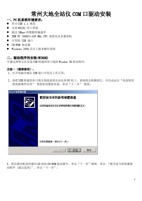
常州大地全站仪COM口驱动安装一、PC机系统环境要求:●符合USB 1.1 规范●支持RS232 串口界面●超过1Mbps的数据传输速率●IBM PC 486DX4-100 MHz CPU 或更高及其兼容机●可用的 USB 端口●CD-ROM 驱动器●Windows 2000及以上版本操作系统二、驱动程序的安装(WIN2K)可通过两种方法安装USB转通用串口线的Window 2K驱动程序:方法一(推荐使用):1、打开电脑并确认USB端口可用且工作正常;2、请把USB转通用串口线分别连接到全站仪和PC机上,系统将会检测到它,并自动运行“欢迎使用找到新硬件向导”帮助你设置新设备。
单击“下一步” 继续;3、将仪器内配套的通讯CD放如CD-ROM驱动器中,单击“下一步”继续。
单击“搜寻适当的装置驱动程序 (建议选项)”,单击“下一步”;14、系统将自动寻找合适的驱动程序并安装,单击“完成”,即说明程序安装完毕。
备注:因PC机的系统配置不同,有的电脑在驱动程序安装完成后即可直接运行程序,有的则不行。
此时应关闭电脑,并重新开机。
(建议如果不能确认电脑是否会自行直接运行驱动程序,可在驱动程序安装完成后直接重新开机。
)5、右击“我的电脑”查看“属性”,选择“硬件”,查看“设备管理器”,你可以看到在“端口”菜单下出现“Prolific USB to Serial Comm Port (COM3)”;2.方法二:1、打开电脑并确认USB端口可用且工作正常;2、将仪器内配套的通讯CD放如CD-ROM驱动器中,并运行CD,双击USB1.1 TO RS232;3、选择PL-2303,双击HL-2303;4、双击HL-2303.exe,等待驱动程序安装,单击“完成”即说明程序安装完毕;备注:因PC机的系统配置不同,有的电脑在驱动程序安装完成后即可直接运行程序,有的则不行。
此时应关闭电脑,并重新开机。
(建议如果不能确认电脑是否会自行直接运行驱动程序,可在驱动程序安装完成后直接重新开机。
Agra-GPS JCB-JD 桥接器安装手册说明书

INSTALLATION MANUAL Agra-GPS JCB-JD Bridge for4xxx and 8xxx TractorsVersion 1.2Revision BNov. 2020Contact informationAgra-GPS Ltd.Box 2585Stony Plain, ABT7Z 1X9CANADA001 780 990 4052 PhoneRelease NoticeThis is the Feb 2020 release (Revision B) of the JCB-JD Bridge Installation Manual.DisclaimerWhile every effort has been made to ensure the accuracy of this document, Agra-GPS Ltd assumes no responsibility for omissions and errors. Nor is any liability assumed for damages resulting from the use of information contained herein. Agra-GPS Ltd shall not be responsible or liable for incidental or consequential damages or a loss of anticipated benefits or profits, work stoppage or loss, or impairment of data arising out of the use, or inability to use, this system or any of its components.DO NOT USE THE JCB-JD Bridge IF YOU DISAGREE WITH THE DISCLAIMER.Important Safety InformationRead this manual and the operation and safety instructions carefully before installing the JCB-JD Bridge.•Follow all safety information presented within this manual.•If you require assistance with any portion of the installation or service of your equipment, contact your Agra-GPS for support.•Follow all safety labels affixed to the system components. Be sure to keep safety labels in good condition and replace any missing or damaged labels. To obtain replacements for missing ordamaged safety labels, contact Agra-GPS.When operating the machine after installing the JCB-JD Bridge, observe the following safety measures: •Be alert and away of surroundings.•Do not operate the JCB-JD Bridge system while under the influence of alcohol or an illegal substance.•Remain in the operator’s position in the machine at all times when the JCB-JD Bridge system is engaged.•Determine and remain a safe working distance from other individuals. The operator is responsible for disabling the JCB-JD Bridge system when a safe working distance has beendiminished.•Ensure the JCB-JD Bridge is disabled prior to starting any maintenance work on the machine or parts of the JCB-JD Bridge system.•Follow all safety instructions from JCB as well as the John Deere!•The JCB-JD Bridge must only be used in the field, never on the street!Electrical Safety•Always verify that the power leads are connected to the correct polarity as marked. Reversing the power leads could cause severe damage to the equipment.•Verify that all cables and connectors are not going over sharp edges and are not pinned, as this could cause power shortages and/or malfunctions.IntroductionCongratulations on your purchase of the JCB-JD Bridge. The JCB-JD Bridge is designed to bridge the communication between a JCB tractor (autosteer ready) and a John Deere display (1800, 2600, 2630, or 4640). This allows a JD display to create maps in the John Deere format and also provides straight AB-Line autosteer.The operator uses the JD display to create AB-lines. The current position is determined by a John Deere receiver and all this information is used by the JCB-JD Bridge to create steering instructions for the tractor. All conditions for autosteer such as minimum speed, steering enabled etc. Must be met by the JCB tractor system before the autosteer engage option in the tractor can be activated.NOTICEThis manual is not intended to replace the manuals for the tractor or the John Deere system. The operator must read and understand the manuals and instructions of these systems, before using the JCB-JD Bridge.Installation of the JCB-JD BridgeJCB Fastrac 4000For JCB 4000 Agra-GPS delivers just the Bridge module itself without any wiring.If you order a new 4000 series JCB, you may want to include the options:130Txxx (regional / spec dependent) or 130T438 - Field Pro Pack (Includes GPS Ready Steering) or GPS ready & Rapid steer130U407 - AGRA GPS READY (Harness & Roof bracket)JCB Landpower offers a JCB Fastrac 4000s CANBUS GPS installation kit.This must to be ordered separate from a JCB dealer.JCB after market service kit p/n - 474/00873There is also the option to order the Fastrac 4000 Agra-GPS ready by manufactory.Please see the JCB Fastrac compatibly document.For the installation of the Bridge for JCB Fastrac 4000 models please see the JCB Fastrac 4000s CANBUS GPS installation manual.JCB Fastrac 8000For JCB 8000 Agra-GPS delivers a Bridge kit including an adapter to connect to the tractor and a harness to connect to the JD display and GPS receiver.The followings steps will show you how to install the Agra-GPS bridge to a JCB 8000.If you order a new JCB 8000 series, you may want to include the options:130G409 or 130G410 - GPS Ready Steering130U807 - AGRA GPS READY (Harness & Roof bracket)Step 1: Mounting the JCB-JD BridgeThe JCB-JD Bridge is installed right of the driver seat.Remove all screws from the lower part of the plastic panel. 2 extra screws are below the cigarette lighter plastic! Remove the top cover carefully as the air outlet is attached with a clamp.Connecting the adapter:Locate the 20 pin “GPS” plugDisconnect the “GPS” plug and connect theprovided Agra-GPS bridge connector.Remove the cover behind the seat.Connect the provided Agra-GPS DTM04-12P plug and the black DTM06-12Sconnector.Step 2: Mounting the JD DisplayThe mounts for the JD display are NOT part of the JCB-JD Bridge, however they can either be ordered as an optional item from Agra-GPS or directly from RAM.The JD-display may be mounted manydifferent ways.You may use the standard JD mounts or aRAM mount. RAM-270U + 2 * 1.5" balls(RAM-202U) + 4" double socket arm (RAM-201U)/part/RAM-270UHere mounted above the JCB screen.Step 3: Installing the antenna harnessThe harness that comes with the JCB Bridge can be routed up behindthe “B” post moulding.In order to route the cable it is necessary to remove the terminals from the 12-way deutsch connector.Remove the internal lock – use a small screrwdriver to flick this out. (or better a deutsch connector removal tool if available) Make a note of the cables and the pin location!Using a small screw driver hold back the terminal lock and the wire will pull out. Remove all the wires from the connector to make it easier to fit through the grommet.Putting electrical tape around the terminals will help routing this cable.Remove the radio/blank and pull out theHV AC control panel. Also remove the main black plastic panel within the roof liner. Locate the tractors radio antenna cable. Use the hole where this comes though and push the JD Antenna cable through this.Locate the Front right-hand work light on the cab roof. Remove the whole work light assembly to gain access in the roof moulding. The JD antenna cable should be accessible. Remove spare grommet (None US machines) and replace with 332/T6792. JD antenna should come through here.Clip and tidy all cabling so no snagging will occur.Once harness is through the grommetthe connector can be refittedStep 4: Mounting the JD ReceiverThe JCB-JD Bridge does NOT include a standard JD-receiver bracketJCB however has one available.Order:Antenna bracket(400/H4801 and 400/E3645)from JCB. Installation instructions come with the kit.Using the JD display you may adjustyour steering performance. Most machines will perform optimally with all JD settings at 100. If a change is required, find an open area where you can travel at target speed and adjust one parameter at a time until you aresatisfied with the steering performance.Step 6: ISO ApplicationThe JCB bridge comes with an ISO application that will be loaded onto the John Deere monitor. The app should automatically store itself on the monitor after the first few minutes of the initial startup. On subsequent runs the app will load itself from memory as soon as possible. The JCB app includes:–Calibration–Option to change work recording mode–Option to change the machine type–Optional autosteer engage button & status–Help pageWhere to find the JCB ISO application on the John Deere monitor:–On a John Deere 4640 the application will beloaded in the ISOBusVT section on themain page of thedisplay.2600, 2630 theapplication will be shownin the side menu of theJohn Deere display. Theside menu is opened byclicking the button on thebottom right of thedisplay.and 2600 monitors do notshow a loading bar forISO applications, while2630 and 4640 monitorsdo.If the ISO application is not loaded:–Try clearing the monitor's memory. On 2630 monitors this can be done in the Message Center in the side menu. Go to the Cleanup tab, check controllers, then Begin Cleanup. On 4640monitors this can be done in the info page of the ISOBus VT. Navigate to the ISOBus VTwindow and click the info button at the top of the page, then press Clean Up ISO Bus VT.–Do a hard reset of the John Deere monitor (Unplug it, then plug it back in).–Do a full restart of the machine. Remember the app may take a few minutes to load.–If calibration is needed and the ISO application cannot be used, navigate to the next section ofthis document.Step 7a: Calibration (JCB8000) - ISOAppSection – Steering Valve: Allows the user to set the left and right max of the JCB machine. Tocalibrate, steer as far left as possible and press, “Set Left”. Then, steer as far right as possible and press, “Set Right”.Section – Transducer: Allows the user to set the steering wheel movement detection. While the machine is running, ensure the wheel angle is straight and the machine is in park. Then, press, “Set Transducer”.Section – Deadband: Allows the user to calibrate the deadband of the valves. Ensure the perimeter around the machine is clear and press the Start/Stop button to begin. An indicator will blink yellow while calibration is in progress and will take approximately five minutes.Step 7b: Calibration (JCB4000) - ISOAppSection – Offset Calibration: Allows the user to calibrate machine steering angle offset. Some machines will not need this calibration, however some machines will. The offset can be changed by pressing on the offset value and entering an appropriate value, or by running offset calibration. In order for offset to take effect, the user must check the offset checkbox at the bottom of the page.Offset calibration is a process that will attempt to determine the correct offset for the user's machine. It is recommended to manually fine-tune the offset slightly after calibration to determine the most accurate offset. Calibration works best on a flat surface. To start calibration, prepare machine for autosteer and press the button labelled, “Calibration Mode”. The label below should change from “Waiting” to “Ready to Engage”. The user can now engage the machine, at which point it will steer straight and collect data for approximately thirty seconds. Progress is shown through a progress bar in the middle of the Offset Calibration section. Once complete, the offset label will be populated with an approximate offset.Step 7c: Calibration (JCB4000) - BackupThe JCB-Bridge must be calibrated to achieve the best possible performance.–Download the zip archive from /download/CalibrationJCB.zip–Unzip the archive and run the Windows installer (.msi file)–Open the Bridge at the front plate (4 phillips screws) and connect the Bridge to a Windows laptop with a mini-usb to USB cable–Run the mbedWinSerial_16466.exe file from the archive. This will add a virtual serial port to the Bridge. Important: The Bridge must be connected during the install!–Now start the installed Calibration application–Press the "Connect" button, the com port should be automatically selected–To calibrate manually, move the offset value up/down and press the "Set Offset" button to set the offset value inside the Bridge. If the machine is hanging towards the right of the line, set the offset to a number below zero, and vice versa. Start off at small values such as -5 to - 10 andadjust accordingly.–To calibrate automatically, drive forward at around 5km/h on even ground and engage the steering. You will need around 15 seconds of driving forward. Once the calibration hascompleted, it will set the "Offset" value to an amount calculated based on the machine’sbehavior. Press the "Set Offset" button to send this value to the Bridge.。
手机终端安装使用说明详解
安装使用说明项目经理(地监)项目经理经常外出,在安装现场协调安装班组与客户的关系,监督管理安装现场与安装质量。
经常需要看一下图纸,及记录现场问题。
传统的做法记录零散,难于归类,纸质材料太多,无法随身携带,查找资料麻烦。
如查看图纸……1、使用工具多种多样,安桌手机、苹果手机、笔记本、平板电脑都可以使用,携带方便2、可以随时查看安装信息。
3、项目经理只有查看自己负责的项目信息4、安装班组组长只有查看自己班组负责安装的电梯信息5、记录了整个电梯的安装过程信息。
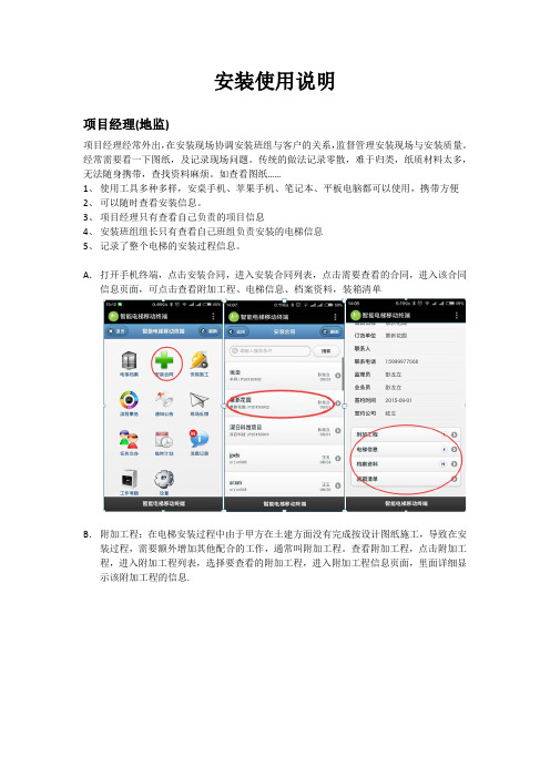
A.打开手机终端,点击安装合同,进入安装合同列表,点击需要查看的合同,进入该合同信息页面,可点击查看附加工程、电梯信息、档案资料,装箱清单B.附加工程:在电梯安装过程中由于甲方在土建方面没有完成按设计图纸施工,导致在安装过程,需要额外增加其他配合的工作,通常叫附加工程。
查看附加工程,点击附加工程,进入附加工程列表,选择要查看的附加工程,进入附加工程信息页面,里面详细显示该附加工程的信息.C . 更新电梯安装进度:方式一:更新电梯安装进度时间信息节点,点击电梯信息进入电梯信息清单页面,点击要更新电梯,进入安装电梯信息页面,添加进度时间节点信息,点击保存即可方式二:更新现场安装进度信息,进入安装电梯信息页面,点击安装进度,在安装进度页面,点击要填写的进度目录,进入安装进度编辑页面,填写安装进度信息,拍照上传附件资料,点击保存即可D.查看档案资料,点击档案资料,进入档案目录页面,该档案目录是整个项目档案资料目录是没发货进场前的地盘的工程资料,填写工程进度档案资料,通过手机终端拍照上传附件资料发货电梯档案资料目录:当现场已经具备进场安装,需要发货,且发货申请单通过审核,在发货申请单下面显示发货电梯信息,点击要查看的发货电梯,进入该电梯的档案资料目录页面,项目经理需要在这些目录中填写好相关档案资料上传附件资料。
点击保存E.装箱清单,现场查看装箱清单确认是否有错漏,无误现场通过手机终端拍照上传。
运输视频终端安装配置与使用手册

主页屏幕
呼叫设置
系统
管理设置
常规设置 系统设置
北京直真视通
主页屏幕
日期和时间设置
系统
管理设置
常规设置
位置
北京直真视通
呼叫首选项设置
主页屏幕
系统
管理设置
网络
呼叫首选项
•呼叫首选项 •呼叫速度 •系统允许的最大接收速率(最大不超过1920K) •需要在呼叫速率下拉框内显示的速率值
北京直真视通
视频终端使用与维护
北京直真视通
选择视频源
选择视频源 按遥控器上的 摄像机。
然后按您要在近端或远端站点 选择的摄像机或视频源的编号。 例如,按 1 可以选择主摄像机。
北京直真视通
声音控制
声音控制包括 音量大小:音量大小的调节即可 以调节你收听到的音量大小,同 时也将调节你送出去的音量大小 静音:按下“静音”按钮,系统静音 后,屏幕左下角会有静音图标
当前状态:远端会场为大画面,本地 会场画面为画中画。 按遥控器上的“近端”按钮,可以将大 画面变为本地画面,画中画自动变为 远端会场画面。
北京直真视通
全屏和主页屏幕显示的切换
在会议过程中,你可能需要 到主页屏幕进行操作,操作完成 后又需要回到会议图像状态,可 以按以下方法进行切换。
当前状态:主页屏幕界面。 按遥控器的“近端”或“远端”按钮, 切换到近端或远端会场画面。
系统状态 呼叫统计 网络 视频 音频 系统重设
常规设置 网络 监视器 摄像机 音频 LAN属性 全球服务
北京直真视通
系统初始设置
系统第一次使用时,开机后需要作一些初始 设置,通常包括语言、国家、系统密码。
密码分为配置密码和幻灯片密码,在系统密 码设置时,系统会使用设备的序列号作为默认的 配置密码。我们建议用户不要设置配置密码或使 用便于记忆的数字和字母组合作为配置密码。
今典蒙太奇数字影院服务器杜比3D安装流程(V1.1)
今典蒙太奇数字影院服务器杜比3D安装流程1,杜比3D系统搭建首先请将杜比3D的色轮、马达和杜比3D的放映机支架按照安装说明书的要求,安装到放映机内。
并确认设备安装是否完备。
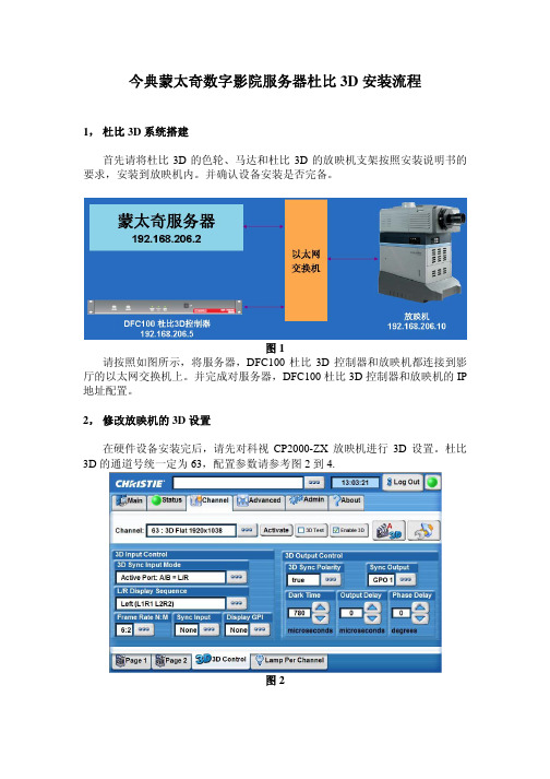
图1请按照如图所示,将服务器,DFC100杜比3D控制器和放映机都连接到影厅的以太网交换机上。
并完成对服务器,DFC100杜比3D控制器和放映机的IP 地址配置。
2,修改放映机的3D设置在硬件设备安装完后,请先对科视CP2000-ZX放映机进行3D设置。
杜比3D的通道号统一定为63,配置参数请参考图2到4.图2图3图43,升级Firmware目前已安装的蒙太奇数字影院服务器的Firmware版本为21.1j(21.1.20-106)。
可以通过服务器触摸屏Menu—>About查看版本信息;为了支持杜比3D现需要将服务器的Firmware升级到21.1y。
升级方法:z将装有升级软件包的U盘插入服务器前面板的USB接口z等待10到15秒后,触摸屏会自动弹出一个文件列表窗口z请用触摸笔点击选择文件fw_dci-21_01y-1.pkg,然后点击屏幕右上方的导入框z此时屏幕上会弹出密码输入框,请用虚拟键盘输入密码1234,并点击确认z系统会自动升级Firmware,并提示升级完成请重启服务器z重新启动服务器4,升级系统软件目前已安装的蒙太奇数字影院服务器的系统软件版本为0.5.2-18 SP1。
可以通过服务器触摸屏Menu—>About查看版本信息;为了支持杜比3D现需要将服务器的系统软件升级到0.5.4-2。
升级方法:z将装有升级软件包的U盘插入服务器前面板的USB接口z等待10到15秒后,触摸屏会自动弹出一个文件列表窗口z请用触摸笔点击选择文件dcp2000_patch-0.5.4-2.pkg,然后点击屏幕右上方的导入框z此时屏幕上会弹出密码输入框,请用虚拟键盘输入密码1234,并点击确认z系统会自动升级,并提示升级完成请重启服务器z重新启动服务器5,安装杜比3D的授权每台蒙太奇数字影院服务器如果要安装杜比3D都需要安装一个针对此台服务器的杜比3D授权,否则杜比3D将无法使用。
Doulecom快速安装手册

多倍通(Doublecom)无线网络产品快速安装手册 做好后如下图所示:
分体设备RJ45接头
一体化设备RJ45接头
请务必保证双绞线和电缆连接器头制作方法正确。为了防止发生短路的情况,推荐在制
作完毕后用仪器测试此段网线的制作是否正确;
安装无线设备时,请务必先将设备与天线连接好后再给设备供电;拆卸、更换无线设
◆ 多倍通(Doublecom) 无线设备一台 ◆ POE 模块及电源适配器一套 ◆ 电源线一根 ◆ 网线一根 ◆ 安装配件一套 ◆ 合格证/保修卡一张 ◆ 光盘一张 如果上述项目中的任一项缺少或损坏,请与本地销售商取得联系。
三:产品介绍
Doublecom 系列高性能无线网络AP/Bridge专为企业和公共接入设计,内置Atheros芯片 组,可提供高性能的网络接入,高稳定性和较大的覆盖范围。支持高达108Mbps的传输速率。 工作于多种不同的模式,适应于多种无线应用,包括长距离网络部署。AP采用可扩展的分离 式天线设计,适用于广泛的无线应用,同时允许你根据信号广播的强度,方 便调节天线位置 , 从而提高无线覆盖和信号强度。POE设计允许将AP部署到电源不容易达到的地方。为保护你 的网络安全和秘密,AP使用多种方式来提高无线安全性能。Bridge采用多样化、多协议支持 模式提高传输链路整体性能。同样整合了独特的高级特性,使AP 更适合进行远距离传输; 当网络布局改变时,生成树协议(STP)可提供额外的冗余备份和自动生成能力。同时还实现 一个设备多种模式传输方式,大大的延伸了传输距离和中继点数据吞吐量。此外Doublecom 还采用了专有协议(Nstreme)和双模块全双工传输模式。大大的提升了网络传输的带宽和质
2、一体化设备的安装: 如下图所示:先将支架安装在一体化设备上,拧紧螺丝;最后用U型卡把设备固定在事
2GIG Vario LCD Keypad安装手册和用户指南说明书
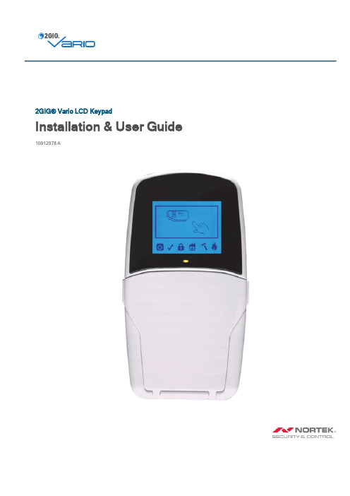
2GIG®Vario LCD Keypad Installation&User Guide 10012978A2GIG Vario LCD Keypad Installation&User Guide THIS PAGE INTENTIONALLY LEFT BLANKCONTENTSInstalling the2GIG Vario LCD Keypad5 Introduction6 Keypad Indicators6 LED(Red)6 Keys7 Numeric Keys7 Keypad Settings8 Using the Proximity Tag9 Automatic Upgrade Resulting from Panel Manual Upgrade9 Technical Specifications9 Ordering Information9 Regulatory Information10 FCC Notice10 Industry Canada(IC)Compliance10 Limited Warranty10 Inquiries102GIG Vario LCD Keypad Installation&User Guide THIS PAGE INTENTIONALLY LEFT BLANK2GIG Vario LCD Keypad Installation&User Guide Installing the2GIG Vario LCD KeypadIntroductionThe user-friendly 2GIG Vario LCD/LCD Proximity keypad enables simple operation and programming of the 2GIG Vario system.The following instructions offer a brief overview of keypad operation.For detailed information on programming the system refer to the 2GIG Vario System Installation and User manuals.KeypadIndicatorsPowerOn System is operating properly from AC power,its backup battery is ingood condition,and there are no troubles in the system.OffNo power.Slow Flash System is in programming mode.Rapid Flash System trouble (fault).ReadyOn System is ready to be armed.OffSystem is not ready to be armed.Slow Flash System is ready to be armed (set)while exit/entry zone is open.Arm (Set)On System is armed in Full Arm or Stay Arm mode.OffSystem is disarmed (unset).Slow Flash System is in Exit Delay Rapid Flash Alarm condition.Stay/Bypass (Part Set/Omit)OnSystem is in Stay Arm or Zone Bypass (Omit)mode.Off No bypass zones in system.TamperOnZone/keypad/external module has been tampered.Off All zones are operating normally.Fire On Fire alarm.OffNormal operation.FlashingFire circuit problem.LED (Red)2GIG Vario LCD Keypad Installation &User Guide2GIG Vario LCD Keypad Installation&User GuideKeysControl KeysKEYPROXWHT,2GIG-VAR-KEYPROXBLK).Used to scroll cursor to theProvidesFunction KeysPressing bothNumeric KeysKeypad SettingsNOTE:The following settings must be defined individually for eachkeypad connected to the system.Use the following procedure to define keypad settings:1.Press fortwo(2)seconds until the Keypad Settings menuappears.2.Select therelevant icon usingtheand keys.To selectan option,press .Brightness ContrastKeypad buzzervolumeLanguageThe 2GIGVario system language option can always be accessed bysimultaneously pressingand.Panel3.Adjust settings with arrow keys.Press to confirm adjusted settings.4.Press to save the adjusted settings.5.Pressexit the keypad settings menu.2GIG Vario LCD Keypad Installation &User Guide2GIG Vario LCD Keypad Installation&User GuideUsing the Proximity TagThe proximity tag,used with the proximity LCD keypad(2GIG-VAR-LCDPROX)is correctly used by applying it within a4cm distance from the front of the keypad bottom,as shown below.This feature is only available on certain keypads.Check with your security provider to see if your keypad supports this feature.Automatic Upgrade Resulting from Panel Manual UpgradeUpon initiation of the2GIG Vario system panel remote upgrade(see the2GIG Vario Installer Manual,Appendix I:Remote Software Upgrade),the LCDkeypad also may be automatically upgraded.During this approximately tree-minute process,an upgrade icon()and the power icon()are displayed on the keypad and the LED light flashes.Do not disconnect during this period.This feature is only available on certain keypads.Check with your security provider to see if your keypad supports this feature.Technical SpecificationsOrdering InformationRegulatoryInformationFCC NoticeThis device complies with Part15of the FCC's Rules.Operation is subject to the following two conditions:1.This device may not cause harmful interference,and2.This device must accept any interference received,including interference that may cause undesired operation.This equipment has been tested and found to comply with the limits for a Class B digital device,pursuant to Part15of the FCC Rules.These limits are designed to provide reasonable protection against harmful interference in a residential installation.This equipment generates,uses,and can radiate radio frequency energy and,if not installed and used in accordance with the instructions,may cause harmful interference to radio communications.However,therre is no guarantee that interference will not occur in a particular installation.If this equipment does cause harmful interference to radio or television reception,which can be determined by turning the equipment off and on,the user is encouraged to try to correct the interference by one or more of the following measures:Reorient or relocate the receiving antenna.Increase the separation between the equipment and receiver.Connect the equipment into an outlet on a circuit different from that to which the receiver is connected.Consult the dealer or an experienced radio/TV technician for help.This product complies with FCC radiation exposure limits for an uncontrolled environment.Avoid operating this product at a distance less than20cm from the user.NOTE:Any changes or modifications not expressly approved by the party responsible for compliance could void the user's authority tooperate this equipment.Industry Canada(IC)ComplianceThis device complies with Industry Canada license-exempt RSS standard(s).Operation is subject to the following two conditions:(1)this device may not cause interference,and(2)this device must accept any interference,including interference that may cause undesired operation of the device.Repairs to certified equipment should be made by an authorized Canadian maintenance facility designated by the supplier.Any repairs or alterations made by the user to this equipment,or equipment malfunctions,may give the telecommunications company cause to request the user to disconnect the equipment.Users should ensure for their own protection that the electrical ground connections of the power utility,telephone lines,and internal metallic water pipe system,if present,are connected together.This precaution may be particularly important in rural areas.Limited WarrantyThis Nortek Security&Control product is warranted against defects in material and workmanship of two(2)years.This warranty extends only to wholesale customers who buy direct from Nortek Security&Control LLC or through Nortek Security&Control LLC's normal distribution channels.Nortek Security&Control LLC does not warrant this product to consumers.Consumers should inquire from their selling dealer as to the nature of the dealer's warranty,if any.There are no obligations or liabilities on the part of Nortek Security&Control LLC for consequential damages arising out of or in connection with use or performance of this product or other indirect damages with respect to loss of property,revenue,or profit,or cost of removal,installation,or reinstallation. All implied warranties for functionality,are valid only until the warranty expires.This Nortek Security&Control LLC Warranty all other warranties expressed or implied.All products returned for warranty service require a Return Authorization Number(RA#).Contact Returns at1-855-546-3351for an RA#and other important details.InquiriesDirect all inquiries regarding this regulatory compliance statement to:Nortek Security& Control1950Camino Vida Roble,Suite150Carlsbad,CA 92008-6517USA800-421-15875IN25982GIG Vario LCD Keypad Installation&User Guide。
JDicom安装、使用指南
JDicom安装、使用指南JDicom安装、使用指南一、安装JDicom1、系统要求JDicom支持在以下操作系统上运行:- Windows 7及以上版本- Linux- macOS2、JDicom光盘或网络上最新版的JDicom安装文件。
3、安装JDicom双击安装文件,根据安装向导一步一步完成安装过程。
二、配置JDicom1、配置DICOM服务器在JDicom中配置DICOM服务器的连接信息,包括IP地质、端口号、用户名和密码等。
2、配置DICOM工作列表设置要接收的DICOM图像的存储位置和格式,以及处理规则。
三、使用JDicom1、DICOM图像的导入和导出- 导入:从DICOM设备或存储介质导入图像到JDicom中。
- 导出:将JDicom中的图像导出到DICOM设备或存储介质。
2、查看和编辑DICOM图像- 查看:在JDicom中浏览和查看DICOM图像,支持缩放、旋转和放大等操作。
- 编辑:对DICOM图像进行标记、测量和注释等操作。
可以添加文本、箭头、矩形框等。
3、图像处理和过滤在JDicom中对DICOM图像进行预处理,包括图像平滑、锐化、增加对比度等。
4、DICOM数据库管理- 新建数据库:创建新的DICOM数据库,并设置数据库的名称和存储路径。
- 导入数据:将DICOM图像导入到数据库中,方便管理和检索。
- 删除数据:从数据库中删除不需要的DICOM图像。
- 检索:根据查询条件,在DICOM数据库中进行图像检索。
5、批量处理DICOM图像在JDicom中对多个DICOM图像进行批量处理,包括导入、导出、编辑、删除等操作。
6、DICOM图像的共享和传输- 共享:将JDicom中的DICOM图像共享给其他用户或系统。
- 传输:通过网络将DICOM图像传输给其他DICOM设备或系统。
7、打印DICOM图像将JDicom中的DICOM图像打印到本地或网络打印机上。
附件:1、JDicom用户手册:pdf:详细介绍了JDicom的安装、配置和使用方法。
Dexcom G5动态血糖仪手机使用攻略2---血糖单位设置

Dexcom G5动态血糖仪手机使用攻略2---血糖单位设置Dexcom G5配合苹果手机使用了一段时间了,越用越别扭。
为什么?就是因为那个别扭的血糖单位显示:mg/dL(毫克每分升),我们国家根本不用这个单位,转换成为国标单位mmol/L(毫摩尔每升)每次都要除以18,你说别扭不别扭。
国产的血糖仪(或者获准在中国出售的进口货)要想mmol/L单位,只要进入设置,选择转换一下就ok。
可是我翻遍了那个Dexcom Mobile G5软件的设置,没有。
不死心,又重装了n遍软件,不得不忍受n次冗长的开机激活过程,希望在每次开机设置中发现有血糖单位选择的选项,结果依旧是没有。
害的我又累白了几根头发,7456!不死心,但毫无办法。
有一次,发现友人(你咋恁多糖尿病友人,没办法,人以群分嘛)在网上晒的手机显示的G5血糖,是mmol单位,马上问她如何设置的?结果她也说不出个456来,只说是友人的友人帮设置的。
我就不服气了,难道友人的友人是多高的高人?。
经过漫长的等待,终于联系到了友人的友人。
结果他说:他一安装就是这个样子的,没经过啥特别设置。
只不过他是加国(加拿大)国籍身份。
一切都豁然开朗了。
因为他的加国国籍身份,就让他有了mmol单位说明啥?说明他的加国苹果id让他下载到的Dexcom Mobile G5软件肯定是不一样的。
Dexcom给各个国家使用的软件版本(很不幸,Dexcom不提供中国大陆使用他的产品)不同,加国是英联邦国家,合理的推测就是:英联邦国家都使用mmol单位,包括我国香港地区。
说干就干,马上注册一个香港苹果id。
都是中国人嘛,语言相通,注册起来应该没难度。
但是香港id注册过程中还是遇到问题:跨不过的必须输入信用卡号,我输入一个建行的VISA卡,结果它提示:不支持,该卡不能在香港地区使用。
7456!我注册米国id时,信用卡可以选择none,应该就是这样嘛:我有不拥有信用卡的权利。
天赋人权嘛。
难道到中国人这里就没人权了?真是岂有此理。
小鸟科技多屏幕拼接器产品说明书v4.0..

多屏幕拼接控制器与分割器说明书重要提示:为了您和设备的安全,请您务必在使用本设备前仔细阅读本安全说明。
如果在使用过程中遇到疑问,请首先阅读本说明书。
正文中有设备操作的详细描述,如仍有疑问,请联系我们,我们将尽快给您满意的答复。
本说明书如有版本变动,恕不另行通知,请谅解。
本公司保留该产品所有权利!目录第一章安全说明 (5)1.1电源 (5)1.2断电 (5)1.3线缆 (5)1.4信号 (5)1.5散热 (5)1.6 环境 (5)1.7维修 (5)1.8设备安装 (5)1.9安全注意事项 (6)第二章概述 (7)2.1多屏幕拼接控制器 (7)2.2系统拓扑图 (10)第三章安装说明 (11)3.1 打开包装 (11)3.2安装机器 (11)3.3机器调试 (11)第四章技术规格 (12)第五章功能介绍 (15)第六章控制软件的基本操作 (17)文案大全6.1基本参数的设置 (17)6.2新窗口的建立 (22)6.3窗口的移动和调整 (23)6.4窗口的关闭 (24)6.5切换和调整窗口的信号源 (24)6.6窗口之间的层次关系 (26)6.7场景的保存与调用 (26)6.8矩阵联控 (27)6.9大屏控制 (28)6.10 像素补偿功能 (29)6.11解除时间限制 (29)第一章安全说明1.1电源请使用带保护地的单相三线制的220V交流电源,并确保整个工程系统使用同接地,不能使用无接地保护的电源,电源线的接地脚不能破坏。
1.2断电在进行设备移动或其它需要断电的情况时,要关闭电源,确保设备安全。
1.3线缆不容许在电源线、信号线、通讯线等线缆上压放物品,应避免对线缆踩踏和挤压,以防止出现漏电和短路等危险情况的发生。
1.4信号确保信号线、通讯线等线材连接好,再开机操作。
1.5散热设备表面的散热孔,不要堵塞,以免热量聚集,损坏设备。
1.6环境设备工作环境要注意防尘,防潮,防止液体浸泡。
1.7维修所有维修工作应有专业人员完成,未经许可,不准私自维修,以免发生触电危险。
电子设备诊断器快速安装指南说明书

Diagnose Controller Quick Installation Manual2Diagnose Controller Quick Installation Manual September 2022 Table of contents1 Abbreviations (4)2 Accessing your Diagnose controller from your PC (4)2.1 Physical network setup (4)2.2 Obtaining your IP address via your router (5)2.3 Accessing your Diagnose controller (5)3 Updating your Diagnose controller to the latest firmware version (7)4 Diagnose controller settings (8)4.1 Time settings (8)4.2 Change password (8)4.3 IP settings (9)4.4 Https certificate (9)4.5 Email settings (10)5 Configuring your Diagnose controller to visualize your low voltage site setup (11)5.1 Exporting the XML file from Eaton Configurator (11)5.2 Uploading the Eaton Configurator file and place sensors (12)5.3 Backup and restore configuration (24)5.4 Eaton Configurator preview picture (24)5.5 Senor list, data backup and restore, delete sensor data (25)5.6 Controller information, reboot, service (25)5.7 Device reset (25)5.7.1 Reset Diagnose controller to factory defaults (25)5.7.2 Reset IP settings to DHCP (25)6 Status box - definitions (26)6.1 Using the alarm list to locate compromised areas for red and amber (27)7 Modbus – definitions (28)7.1 Modbus-TCP register explanation (28)7.1.1 Modbus slave (28)7.1.2 Alarm codes (29)7.1.3 Sensor position (29)3Diagnose Controller Quick Installation Manual September 2022 1. AbbreviationsxDC Diagnose controllerRF Radio frequency2. Accessing your Diagnose controller from your PCThe Diagnose Controller can be directly accessed from your computer by using the web browser on your computer.In order to access the xDC, it is important that the PC and your xDC be placed in the same network.2.1 Physical network setup1. Connect your xDC to your computer network, by using an Ethernet network cable.2. To obtain the IP address for accessing the xDC web server through your web browser, then use IPaddress assigned by your IT team or follow the instruction set 2.2 for using your own router.3. In case of missing DHCP server (timeout for searching: 10min), a fix IP address (169.254.1.15) isavailable for the Diagnose controller.4. When you have the IP address then move to Instruction set 2.3.4Diagnose Controller Quick Installation Manual September 2022 2.2 Obtaining your IP address via your router1. Ensure that both your computer and xDC are connected to the same router.2. Read the instruction manual of your router, or check the type label of the router in order to access therouter directly.To access the router directly you will need the following information:• The Router IP address that you need to type directly into your web browser.• The default username and password that you need to login into the Router.3. Upon accessing the router web page, navigate to the DHCP clients list to find out the assigned IP.address for the xDC2.3 Accessing your Diagnose controller2.3.1Once you have the correct IP address for the xDC, type it into your web browser.5Diagnose Controller Quick Installation Manual September 2022 2.3.2When you arrive to the Login screen, enter the following details for Login:In case of first login choose Administrator as per default password: eaton_diagnoseFull access for uploading.XML-file and doing configuration / sensor arrangement etc.Viewer mode can be entered if configuration was successfully uploaded before / 2nd login after configuration limited access just for visualization the running application on an HMI.2.3.3Correct entry of login details will take to the Site Configuration page – click on the arrow bring you back to thelogin screen. Non-admins cannot access the settings page and cannot change any settings of the diagnose controller.6Diagnose Controller Quick Installation Manual September 2022 3. Updating your Diagnose controller to the latest firmware3.1 You can update your xDC to the latest firmware version:Download the latest firmware version from Eaton Download Center:ftp:///AUTO MATIO N/ O AD/XNT/XNT-CTRL-00_01. Copy all file from diagnose_offline_update_x-y-z.zip on empty, formatted DO WNLUSB Stick. Insert USB stick in USB port of Diagnose Controller. The bottom configuration icon changes to red and is displayed with the red text “update available” next to it. Open Configuration page (or reload it, if already opened).Press the “Update Software” button.3.23.3Upon direction to the Waiting for Software Update, please allow 15 minutes to pass while waiting for the device toreboot and automatically redirect back to the site configuration page.3.4After about 15 minutes, you will be re-directed to the Site Configuration page and the Software Update section willno longer be displayed. This section will only be shown when another update is available.7Diagnose Controller Quick Installation Manual September 2022 8Diagnose Controller Quick Installation Manual September 2022 4.1Time settingsClick on “Diagnose controller settings”- Button, insert current date and time and click on “Change Time”- button.4.2Change passwordClick on “Diagnose controller settings”- button.For change the Login-Password fill in the current password, choose Administrator or Viewer, enter the newpassword and repeat it. Default for Viewer is no password (auto-login)Press “Change Password” button.4. Diagnose controller settings9Diagnose Controller Quick Installation Manual September 2022 Password length should be minimum 6 characters and must meet at least 3 out of the following 4 complexity rules: • at least 1 uppercase character (A-Z) • at w character (a-z) • at least 1 digit (0-9)• at least 1 special character (punctuation)4.3IP settingsClick on “Network Settings”- button.Standard mode is DHCP – IP-address will create from the Ethernet network If you want to set fix IP-address, change to mode “Static” and fill in the fields and save the IP settings.Fill in NTP server if needed.4.4Https certificateClick on “Network Settings”- button.An externally signed certificate can be upload.10Diagnose Controller Quick Installation Manual September 2022 4.5Email settingsClick on “Network Settings”- button.Fill in the settings for the e-mail. Test e-mail could be send.Alarms are sent by e-mail to specified address(es). Language of e-mail is set when e-mail settings are saved: ifpreferred language of browser is set to german, e-mails are sent in german; otherwise e-mails are sent in English.The xDC requires an XML file export of your site configuration from the Eaton Configurator xEnergy tool. Follow the instruction set 5.1. to obtain the XML file from the Eaton Configurator xEnergy tool. When you have this XML file available on your PC then proceed to the next instruction set 5.2.5.1Exporting the XML file from Eaton configurator 1. Once you have the completed configuration of your xEnergy Site, using the Eaton Configurator xEnergy tool, navigate to the menus:File > Export.2. When the Export popup window comes up, ensure that the Format setting is XML project description.Under Filename, use the Button to select filepath, and to enter the name that would like the XML file to besaved under.Finally click the Export button to carry out the export.5. Configuring your Diagnose controller to visualize your low voltage site setup3. Once the export is complete and successful, the Transfer project popup window should come up with theinformation that “The project has been exported successfully”. Continue to instruction set 4.2 to continue configuring the visualization your xDC.5.2 Uploading the Eaton Configurator file and place sensors5.2.1 Click on “Site Configuration” button.5.2.2 Click the Browse button to find the Eaton Configurator XML file export to upload.Selected the file and it will be upload.5.2.3Once the xDC has completed the upload process, you will be re-directed to the Distribution Board SiteOverview Page. On this page you can see all the sections visualized.5.2.4Hovering over a section with your mouse highlights the section for selection.Clicking on section will direct to the Section View.5.2.5The Section View allows you to view all the recommended sensor positions for that particular section.5.2.6Hovering over a sensor area highlights the selected sensor. Clicking on the sensor will direct you to the Sensorpage for that particular sensor location.5.2.7To assign a sensor, select it from the dropdown menu if already detected by the system. Otherwise manually enterthe sensor number in the Serial Number entry box. You can add any comments regarding the sensor in thecomment box. Upon completion selected the “Assign Sensor” button in order to assign the sensor to that position.5.2.8Fill in correct number of digits for serials of sensors – otherwise warning field informs you:Busbar: 5 digitsAmbient: 7 digits5.2.9Assignment of the sensor takes the user to the assignment of the next unassigned sensor of the current section.After all sensors of current section are assigned, it brings you back to the Section View. If the sensor has not yet sent a signal to the xDC then a question mark will be displayed in the box, otherwise the sensor temperature reading will be displayed in the box. The sensor assignment can be continued in the same fashion for all sensors.5.2.10 To assign an ambient sensor, click on the sensor on the top of section view. Manually enter the sensor number inthe serial number entry box and select channel. You can add any comments regarding the sensor in the comment box. Upon completion selected the “Assign Sensor” button in order to assign the sensor to that position.5.2.11It is the ability to set own thresholds for warning and alarms. Click off the “Default” checkbox and enter the values.5.2.12 To create a new sensor position choose any sensor position. After that click on “Create a new Sensor Position”and select the x and y-Position in % - press “Create Position”.You can modify or remove the new position.5.2.13 You can remove the sensor or replace it with other sensor.5.2.14 Table view of all sensorsOn the “Site View” by clicking on the link will bring you to the list of all sensors.By clicking on the head of the table, you can sort the values. Clicking on the Field will bring you the Section View;Clicking on the Serial number will bring you to the Sensor View.5.2.15 Clicking on an assigned sensor location from the Section View page will direct you to the Sensor View. On thispage you can view the sensor specific data, including the all the current day values, a 4 weeks graph(1 temperature value all 10min) and trend values for the past 180 days.The sensor data shows the last time, when the sensor send a date; the temperature of the copper; the sensor signal strength.On further details you see: the battery voltage of the ambient sensor or the generated voltage depends on the current; the PCB-Temperature; the maximum allow current (if it is a current sensor).21Diagnose Controller Quick Installation Manual September 2022 The Day graph shows the values of today and will reset at 0 o’clock. With the cursor you can move over the graph and it shows the values at this time.Both values for temperature and current will shown in the graph.In the 4 weeks graph use scroll wheel to zoom and drag to pan – on external display use double-touch to zoom in and use“Reset Zoom” button to zoom back.4 WEEKS VALUEThe Trend value graph shows minimum, maximum and average values of the last 180 days.22Diagnose Controller Quick Installation Manual September 2022 5.2.16 Delete DateYou can delete the saved date of each sensor in the Sensor Assignment – the Sensor Setting will be stay.Select type of shown data with buttons.23Diagnose Controller Quick Installation Manual September 2022 24Diagnose Controller Quick Installation Manual September 2022 5.3 Backup and restore configuration5.3.1 In the “Site configuration” page it is possible to back up your complete configuration (section and Sensors).Press “Backup Configuration“ button and save the file.5.3.2 To restore the site configuration click the “Browse” button to find the file. On clicking on the file will restore thesite configuration.5.4 Eaton configuration preview pictureClick the “Browse” button to find the picture (jpg), by clicking on the file will upload screenshotYou see the preview picture; use the “Delete” button to remove the picture5.5 Senor list, date backup and restore, delete sensor dataPress the Create File button to create an Excel sensor list. Press on Download to save the data. Do it in the same way with sensor date. Restore the sensor date is similar to the configuration file.Delete Data.Delete data for all sensors with5.6 Controller information, reboot, serviceOn Diagnose controller setting are information about the xDC, reboot the controller and send service data.5.7 Device reset5.7.1Reset Diagnose controller to factory defaults available by inserting an USB stick with a special file in root directorynamed EatonDiagnoseCommands.txt with the content DoFactoryReset.• Reset all IP settings (i.e. setting it to DHCP)• Delete database• Reset password• Reset xComfort USB interface CKOZ-00/145.7.2Reset IP settings to DHCPAvailable by inserting an USB stick with a special file in root directory named EatonDiagnoseCommands.txt with the content ResetIpSettings.• Reset all IP settings (i.e. setting it to DHCP)25Diagnose Controller Quick Installation Manual September 2022 6 Status box - definitionsThe status box is displayed on the Site, Section and Sensor view pages in the top page areas.The status box should be interpreted as following:26Diagnose Controller Quick Installation Manual September 2022 6.1 Using the alarm list to locate compromised areas for red and amberTo quickly determine the sensor location causing the state change that you click the Alarm icon to view the cause of the state change, text description of the sensor location and the suggested remedy. All areas causinga state change requiring attention will be highlighted in this list. For the Section view click the alarm text in theSection column for further details. Active alarms are represented in Red. Previous alarms not requiring any actionwill be represented in green.The Alarm list provides the user with text description of the compromised location. To visually identify the location and see the specific sensor details.1. C licking the text in the “Section” column will navigate you to the “Section View”2. S elect a highlighted sensor location for more details3. C arry out recommended actionsOrlicking the text in the “Position” column will navigate you to the relevant sensor1. C27Diagnose Controller Quick Installation Manual September 2022 7 Modbus – definitions7.1 Modbus-TCP register explanation7.1.1. Modbus slaveThe measured values and certain alarms are made available via a virtual Modbus slave (Server) over Modbus / TCP (IEC 61158). A maximum of 3 parallel Modbus connections is possible. Port-number is 502 (as in the standard).function/register type is 03 (read holding registers). Only 1 register can be read by one read command!If device address scheme is used, register 0 is found at address 400001. Please be aware that 5-digits addressing (register 0 at 40001) would not be sufficient as there are more than 9999 registers in use.Data retrieval is done via the Modbus register address by a Modbus master (client), where the 12 MSBs aredetermining the sensor-ID (which is not the serial number, written on the sensor!) and the 4 LSBs the measurand.With the serial number (which can be read out via Modbus with the sensor-ID) the sensor can be identified in the web interface. Sensor-ID 0 is reserved for special queries (alarms). To find out all assignments of sensor-IDs to serial numbers, just read out all available serial numbers. If there are 100 sensors, read out following Modbusregisters: 0x001B/0x001C, 0x002B/0x002C, ..., 0x064B/0x064C.The measurand is defined as follows:0x0 ... Temperature0x1 ... Temperature PCB (only busbar sensors)0x2 ... value of electrical current ([A], as 16 Bit integer value)0x3 ... Pending alarms for this sensor, each Bit used as a flag (see 7.1.2)0x6 ... Section number of sensor0x7 ... Sensor position and phase (see 7.1.3)0x8 ... RSSI0x9 ... Supply/Battery voltage x 10.00xA ... Sensor Type (0..busbar, 1..xComfort)0xB ... Serial (MSBs)0xC ... Serial (LSBs)0xD ... Datapoint (12 LSBs) / Channel No (4 MSBs) (only xComfort sensors)0xE ... Timestamp UTC of last transmission (MSBs)0xF ... Timestamp UTC of last transmission (LSBs)Example: Modbus register address 0x00A0 holds the 2-Byte value of the current temperature of sensor withID 10. 0x00AE and 0x00AF holds the 4-Byte value of its last data timestamp.Alarms: Register-Address 0x00004 MSBs ...Alarm-Code (see 7.1.2)... lowest code if multiple alarms are pending... 0 if no alarm is pending12 LSBs ...Sensor-ID, if only one Alarm on one sensor is pending... 0 if more alarms are pending or more sensors are affectedRegister-Address 0x0000 + Alarm-Code (e.g. 0x0001 for Temperature-alarm or 0x000C for Voltage-alarm)4 MSBs ... Number of sensors affected12 LSBs ... Sensor-ID of affected sensor (lowest ID if more Sensors areaffected)28Diagnose Controller Quick Installation Manual September 2022 7.1.2. Alarm codesIn case of bit-coded alarms (pending alarms for one sensor), the LSB is Bit 0, and the MSB is Bit 15.Example: The bit-coded alarm 0x0602 [Bit pattern 0000 0110 0000 0010] has Bit 1, Bit 9 and Bit 10 set.According the following list, this means that this sensor has triggered a temperature alarm (Bit 1, code 0x0002),a current warning (Bit 9, code 0x0200) and a low signal strength information (Bit 10, code 0x0400).Alarms• Bit 0 (0x0001): LSB, Not defined• Bit 1 (0x0002): Temperature maximum reached:o Main busbar back: T > T_maxo Main busbar top: T > T_maxo ACB/MCCB connection: T > T_maxo Dropper busbar: T > T_max• Bit 2 (0x0004): High internal sensor temperature: T_pcb > T_maxpcb• Bit 3 (0x0008): High ambient Temperature: T_amb > T_maxamb• Bit 4 (0x0010): Abnormal temperature raising, not implemented• Bit 5 (0x0020): Current higher than thresholdWarnings• Bit 6 (0x0040): Temperature threshold prewarning: T > (T_max - 10K)• Bit 9 (0x0200): Current higher than 95% of threshold currentInfos• Bit 10 (0x0400): Low sensor signal strength: RSSI value < -90dBm• Bit 11 (0x0800): Signal not received: no signal since 5min (xComfort: 12h)• Bit 12 (0x1000): Battery/Voltage too low: voltage < 3.0V7.1.3 Sensor positionThe sensor position is coded as follow:Bit 0-7: Position1: Main busbar top2: Main busbar top double3: Main busbar bottom4: Main busbar bottom double5: Main busbar roof6: Vertical dropper busbar top7: Vertical dropper busbar bottom8: Horizontal dropper busbar......Bit 8-9: Phase0: N1: L12: L23: L329Diagnose Controller Quick Installation Manual September 2022 Follow us on social media to get the latest product and support information.Eaton is an intelligent power management company dedicated to improving the quality of life and protecting the environment for people everywhere. We are guided by our commitment to do business right, to operate sustainably and to help our customers manage power - today and well into the future. By capitalizing on the global growth trends of electrification and digitalization, we’re accelerating the planet’s transition to renewable energy, helping to solve the world’s most urgent power management challenges, and doing what’s best for our stakeholders and all of society.Founded in 1911, Eaton has been listed on the NYSE for nearly a century. We reported revenues of $19.6 billion in 2021 and serve customers in more than 170 countries. For more information, visit . Follow us on T witter and LinkedIn .Eaton is a registered trademark.All trademarks are property of their respective owners.Eaton Industries Manufacturing GmbH © 2022 Eaton Publication No. MN145002EN All Rights Reserved September 2022。
金三立产品操作说明及安装

•
品质改善,我们需要全员参与。10:00:2110:00:2110:009/12/2020 10:00:21 AM
•
爱惜物料,重视品质,合理规划,标 识清晰 。20.9.1210:00:2110:00Sep-2012-Sep-20
•
落实拜访,本周破零,活动管理,行 销真谛 。10:00:2110:00:2110:00Satur day, September 12, 2020
网络服务器软件操作说明
搜索软件的使用
1、首先安装好光盘的客户端软件后,桌面上自动生成一个搜索图标, 连接好设备后点击后出现此搜索框,这就是你设备里面的IP地址。
2、双击搜索出的IP地址,出现以下对话框,你可以修改设备的IP、子网 掩码、网关、MAC地址。
3、点击“修改网络参数”按钮后弹出此框,点击“是”按钮,就修改成 功。
24、远程升级:点击“其它设置”—“远程升级”通过网络可以对服务 器进行远程重启、恢复默认值、远程升级等操作。
室外一体化彩色球机
ST-CC9229RC
彩色半球摄像机 ST-CC4095
开发背景
由于一般的半球摄像机在室内安装时色滚问题,即半球 摄像机 一般为直流12V供电、手动光圈或固定光圈、固定 焦距镜头, 因此,半球摄像机同步方式只有内同步,当安 装在室内时,主要光源为日光灯,由于日光灯的频率与摄像 机内同步的频率不 一致,而导致色滚问题。而要解决色滚 问题,有二种方法,一、日光灯的整流器该为电子整流器, 二、采用交流供电方式(即电源同步)。
21、录像查询:点击“通道参数”—“录像查询”选择要查询的类型、 日期、时间后点击“查询”,文件就在框中显示,双击某个文件即可 进行播放。也可以下载到本地计算机上。
22、用户管理:点击“其它配置”—“用户管理”可以添加、修改、删 除用户、用户访问权限设置等。
金立手机PC同步工具安装使用指南

金立手机PC同步工具安装使用指南
金立PC 同步工具安装使用指南
1,将随机附赠的T 卡中的“网络摄像头驱动.rar ”,“金立手机PC 同步工具.rar ”拷贝至电
脑并解压。
2,安装USB 驱动
进入“网络摄像头驱动”,点击InstallDriver.exe 安装。
出现下述提示安装成功。
3,安装PC 工具
点击“金立手机PC 同步工具.exe ”安装。
出现下述提示安装成功4,点击打开PC 同步工具,用USB 线连接手机和PC ,手机端选择“序列端口”项。
进入手机工具—>设置,COM 口处选择相应端口 G i O
N E E
连接成功后PC 工具右下角提示“已连接!”
5,连接成功后即可使用PC 工具管理您的电话簿、信息和其他资料
6,您可以将手机作为无线modem ,连接PC 访问网络。
(1)进入设置->创建连接,选择连接对象,点击“创建”
G i O N E E
(2)创建连接成功后,进入设置->拨号。
点击拨号按钮,拨号连接
G i O
N E E
(3)拨号成功后即可使用PC 通过手机的GPRS 连接上网
注:此功能会产生较高的GPRS 流量,详情请咨询您的网络运营商。
G i O N E E。
杭州希基视觉数字技术有限公司 LCD 显示器用户手册说明书

User ManualUser ManualCOPYRIGHT ©2018 Hangzhou Hikvision Digital Technology Co., Ltd.ALL RIGHTS RESERVED.Any and all information, including, among others, wordings, pictures, graphs are the properties of Hangzhou Hikvision Digital Technology Co., Ltd. or its subsidiaries (hereinafter referred to be “Hikvision”). This user manual (hereinafter referred to be “the Manual”) cannot be reproduced, changed, translated, or distributed, partially or wholly, by any means, without the prior written permission of Hikvision. Unless otherwise stipulated, Hikvision does not make any warranties, guarantees or representations, express or implied, regarding to the Manual.About this ManualThis Manual is applicable to the Monitor.The Manual includes instructions for using and managing the product. Pictures, charts, images and all other information hereinafter are for description and explanation only. The information contained in the Manual is subject to change, without notice, due to firmware updates or other reasons. Please find the latest version in the company website (http:// /en/).Please use this user manual under the guidance of professionals.Trademarks Acknowledgementand other Hikvision’s trademarks and logos are the properties of Hikvision in various jurisdictions. Other trademarks and logos mentioned below are the properties of their respective owners.Legal DisclaimerTO THE MAXIMUM EXTENT PERMITTED BY APPLICABLE LAW, THE PRODUCT DESCRIBED, WITH ITS HARDWARE, SOFTWARE AND FIRMWARE, IS PROVIDED “AS IS”, WITH ALL FAULTS AND ERRORS, AND HIKVISION MAKES NO WARRANTIES, EXPRESS OR IMPLIED, INCLUDING WITHOUT LIMITATION, MERCHANTABILITY, SATISFACTORY QUALITY, FITNESS FOR A PARTICULAR PURPOSE, AND NON-INFRINGEMENT OF THIRD PARTY. IN NO EVENT WILL HIKVISION, ITS DIRECTORS, OFFICERS, EMPLOYEES, OR AGENTS BE LIABLE TO YOU FOR ANY SPECIAL, CONSEQUENTIAL, INCIDENTAL, OR INDIRECT DAMAGES, INCLUDING, AMONG OTHERS, DAMAGES FOR LOSS OF BUSINESS PROFITS, BUSINESS INTERRUPTION, OR LOSS OF DATA OR DOCUMENTATION, IN CONNECTION WITH THE USE OF THIS PRODUCT, EVEN IF HIKVISION HAS BEEN ADVISED OF THE POSSIBILITY OF SUCH DAMAGES.REGARDING TO THE PRODUCT WITH INTERNET ACCESS, THE USE OF PRODUCT SHALL BE WHOLLY AT YOUR OWN RISKS. HIKVISION SHALL NOT TAKE ANY RESPONSIBILITES FOR ABNORMAL OPERATION, PRIVACY LEAKAGE OR OTHER DAMAGES RESULTING FROM CYBER ATTACK, HACKER ATTACK, VIRUS INSPECTION, OR OTHER INTERNET SECURITY RISKS; HOWEVER, HIKVISION WILL PROVIDE TIMELY TECHNICAL SUPPORT IF REQUIRED.SURVEILLANCE LAWS VARY BY JURISDICTION. PLEASE CHECK ALL RELEVANT LAWS IN YOUR JURISDICTION BEFORE USING THIS PRODUCT IN ORDER TO ENSURE THAT YOUR USE CONFORMS THE APPLICABLE LAW. HIKVISION SHALL NOT BE LIABLE IN THE EVENT THAT THIS PRODUCT IS USED WITH ILLEGITIMATE PURPOSES.IN THE EVENT OF ANY CONFLICTS BETWEEN THIS MANUAL AND THE APPLICABLE LAW, THE LATER PREVAILS.EU Conformity StatementThis product and - if applicable - the supplied accessories too are marked with"CE"and comply therefore with the applicable harmonized European standards listed under the EMC Directive 2014/30/EU,the LVD Directive 2014/35/EU,the ROHSDirective 2011/65/EU.Regulatory Information Please take attention that changes or modification not expressly approved by the party responsible for compliance could void the user’s authority to operate the equipment.FCC compliance: This equipment has been tested and found to comply with the limits for a Class A digital device, pursuant to part 15 of the FCC Rules. These limits are designed to provide reasonable protection against harmful interference when the equipment is operated in a commercial environment. This equipment generates, uses, and can radiate radio frequency energy and, if not installed and used in accordance with the instruction manual, may cause harmful interference to radio communications.Operation of this equipment in a residential area is likely to cause harmful interference in which case the user will be required to correct the interference at his own expenseFCC ConditionsThis device complies with part 15 of the FCC Rules. Operation is subject to the following two conditions:1. This device may not cause harmful interference.2.This device must accept any interference received, including interference that may cause undesired operation.FCC Information2012/19/EU (WEEE directive): Products marked with thissymbol cannot be disposed of as unsorted municipal waste in the European Union. For proper recycling, return this product to your local supplier upon the purchase of equivalent new equipment, or dispose of it at designated collection points. For more information see: 2006/66/EC (battery directive): This product contains a battery that cannot be disposed of as unsorted municipal waste in the European Union. See the product documentation for specific battery information. The battery ismarked with this symbol, which may include lettering to indicate cadmium (Cd), lead (Pb), or mercury (Hg). For proper recycling, return the battery to your supplier or to a designated collection point. For more information see: Industry Canada ICES-003 ComplianceThis device meets the CAN ICES-3 (A)/NMB-3(A) standards requirements.Applicable ModelsThis manual is applicable to the model: LCD Monitor.Symbol ConventionsThe symbols that may be found in this document are defined as follows.LCD Monitor User ManualTABLE OF CONTENTS1.Introduction (1)1.1 Key Features (1)1.2 Power Supply Connection (1)2.Device Interfaces (2)3.Panel keys (2)4.Basic Operation (3)Specifications (9)Structure Figure (10)Chapter1.Introduction1.1Key FeaturesDS-D5019 Series:Support1366×768HD display;DS-D5022/5024/5027 Series:Support s1920×1080FHD dispiay;User-friendly operation menu;Three image modes to adapt different environment;1channel HDMI1.3input interface;Support software spread-spectrum technology to reduce EMI radiation;Standby PowerConsumption is lower than 0.5W;DS-D5019 Series:Viewing Angle:Horizontal 90°, Vertical 65º;DS-D5022QE-B:Viewing Angle:Horizontal 170°, Vertical 160º ;DS-D5022QE-E:Viewing Angle:Horizontal 90°, Vertical 65º ;DS-D5024QE:Viewing Angle:Horizontal 178°, Vertical 178º ;DS-D5027QE:Viewing Angle:Horizontal 170°, Vertical 170º ;2Wx2 Speakers efficient output(optional);1.2Power Supply ConnectionInsert the3-pin power device into well-grounded socket and turn the rocker switch on.Figure1.1Power InputPower input specification from100VAC to240VAC or provide automatic switching between high line and low line input ranges.Turn off the main power switch of the display unit,and pull the plug from the power outlet if the display unit will not be used for a long time.Never connect the device to a DC power.Chapter2.Device InterfacesChapter3.Panel KeysKeys on lower right corner of the display unit panel are shown in the Figure 3.1Keys on the DisplayUnit.Figure 3.1Keys on the Display UnitThe functions of the keys on lower right corner of the display unit vary according to different situations.InterfacesInterfacesInterfaces123Chapter4.Basic Operation4.1Input Source Selection(optional)Turn on the display unit when the power supply is on and input source is confirmed.Press ◄ key of the remote controller to enter the menu as shown on the right. DS-D5019/22 /24/27inch LCD display unit includes 2 input sources as HDMI and VGA signal. Press direction keys to select the input source and press MENU to accomplish the input sourceselection.Figure 4.1Input Source4.2Input Audio Volume Adjustment(optional)Turn on the display unit when the power supply is onand input source is confirmed.Press ►key of the remote controller to enter the menu as shown on the right.press ◄or ►to adjust the value of volume.press MENU to accomplish the volumeadjustment.Figure 4.2AudioVolume 4.3Auto AdjustTurn on the display unit when the power supply is onand input source is confirmed.Press AUTO key of the remote controller to enter the menu as shown on the right(In VGASignal).Figure 4.3Input SourcePress key of the remote controller to enter the menu as shown on the right . press ◄ or ► to adjust the valueof contrast.Press MENU to accomplish the contrast adjustment .Figure 4.1 Input Source◄4.1Contrast4.2Figure 4.2 BrightnessBrightnessPress ► key of the remote controller to enter the menu as shown on the right.press ◄ or ► to adjust the value of Brightness . press MENU to accomplish the Brightness adjustment.4.4Main Menu4.4.1Image SettingsPurpose:You can adjust the picture parameters by switching image modes and adjust the values of contrast, brightness,color temperature,auto adjust,color adjust.Steps:1.Press MENU key to enter the main menu interface as shown below.2.Press MENU key to enter the setting you want.3.Press◄or►to adjust the value.It applies for adjusting contrast,brightness,color temp and otherparameters.Contrast,Brightness:Press◄or►to set the contrast,the range varies from0-100.Color temperature:Press◄or►to set the color temperature you need.Gray indicates that under current mode or current input source condition it is not adjustable;Yellowindicates that it is adjustable.4.Press AUTO key to return to the main menu after accomplishing the adjustment.Figure4.4.1Image Settings4.4.2Image AdjustmentPurpose:When the input source is selected VGA,you can adjust the VGA parameters.It is for adjusting VGA H position,V Position,clock and phase.Steps:1.Press Menu key to enter the main menu interface.2.Press◄key to enter the VGA parameter setting interface.(You can select Auto Adjust and press◄or►to adjust the VGA parameters automatically or adjust it manually)3.Select H Position and press◄or►to adjust the H Position4.Select V Position and press◄or►to adjust the V position.5.Select Clock and press◄or►to adjust the clock.6.Select Phase and press◄or►to adjust the phase.The range of the adjustment varies between0-100.7.Press MENU key to return to the main menu after accomplishing the adjustment.Figure4.4.2Image AdjustmentPurpose:You can set the language,blending and OSD duration of the menu.Steps:1.Press MENU key to enter the main menu interface.2.Press◄key twice and press MENU key to enter the【Language】interface,press◄or►to switchthe language you want.3.Select OSD H.Pos/OSD V.Pos to adjust the position of OSD with◄or►.4.Select OSD Timer to adjust the OSD duration with◄or►:5Sec~60Sec.5.Select Transparency to adjust the OSD transparency value with◄or►.6.Press AUTO key to return to the main menu after accomplishing the adjustment.Figure4.4.3OSD SettingPurpose:You can set Mode,Audio Volume,Signal Source,Aspect Ratio,DCR.Steps:1.Press MENU key to enter the main menu interface.2.Press triple◄key and press MENU key to enter the Mode interface,press◄or►to switch the modebetween PC/GAME/MOVIE.3.Press◄or►to adjust the Audio Volume from0~100(optional).4.Press◄or►to change the Signal Source between VGA and HDMI(optional).5.Press◄or►to switch the Aspect Ratio between16:9/AUTO/4:3.6.Press◄or►to switch the DCR On/Off.7.Press MENU key to return to the main menu after accomplishing the adjustment.Figure4.4.4Other SettingsPurpose:You can reset settings to the factory defaults.Steps:1.Press MENU key to enter the main menu interface.2.Press◄key4times and press MENU key to reset settings to the factory defaults.Figure4.4.5Reset SettingS tructureStructure FigureAppendix:SpecificationsStructure FigureAppendix:Specifications16Structure Figure22.544717PN:G6AUM027000029。
金万维天联高级版安装使用说明书

®
北京金万维科技有限公司 2010 年 03 月 01 日
产品部文档
目 录
第一章 系统..........................................................................................................................................................- 3 1.1 关于天联高级版系统简介......................................................................................................................- 3 1.2 系统要求..................................................................................................................................................- 4 1.3 系统快速安装..........................................................................................................................................- 5 1.4 在线组管理平台..................................................................................................................
创维液晶拼接控制器操作手册
控制软件
1 软件系统概述
创维拼接控制软件采用目前软件设计的前沿理念,摒弃传统拼接器控制软件复杂 的调试要求, 对拼接过程实现自动运算, 对窗口控制过程采用所见即所得的操作界面, 避免传统的拼接器软件繁琐复杂的预设过程;经过简单的培训, 就可以完成对该套软件 的使用。 软件整合墙体拼接控制和窗口控制为一体, 运行该软件可以方便完成对场景的模 式设置、调用、窗口的控制、信号通道选择等功能。
4. 信号线连接
从设备上插、拔信号线时,设备需要断电,以免损坏设备。带电插拔造成的损坏不在保 修范围。
5. 散热孔
设备外表面可能有散热用的开孔,不要堵塞这些开孔,以免热量积聚,损坏设备或造成 火灾等危险。
6. 设备安置
应合理安置设备,如装入标准机架、机箱、机柜,或放置在稳固平整的工作台面上,防 止设备跌落。
2. 可靠性
采用专用工控机箱, 在提高系统可靠性方面做了许多特殊设计,可靠性大大优于基 于PC或者嵌入式的同类产品。
3. 高速实时性
采用了运动侦测与补偿运算、 内插运算、边缘平滑处理及杂波信号抑制等尖端处理 技术,可将普通PAL/NTSC 隔行扫描视频信号转变为逐行扫描的、高画质、高分辨率 的完全实时高清电视和计算机图像信号。在处理RGB输入信号时图像质量好、流畅、完 全实时。
7. 环境
设备工作的环境要注意防尘、防潮,尤其要防止液体浸泡和溅入设备内部。
8. 维修
所有的维修工作应由专业维修人员完成,未经培训不要尝试自己维修设备。为防止电击 危险,不要擅自打开机壳。
9. 安全注意事项
9.1 设备内部有高压电,非专业维修人员不得打开机箱,以免发生危险; 9.2 严禁水滴或水溅,严禁在设备上放置任何装有液体的容器物品; 9.3 为预防火灾,禁止设备靠近火源; 9.4 为了充分通风,设备前后面板至少应保持20CM的空隙; 9.5 设备如发出怪异噪音、冒烟或怪味,应立即拔掉电源插头,由专业维修人员处理; 9.6 在有雷电或长期不用的情况下,请拔掉电源插头; 9.7 不要从本设备通风孔塞入任何物体,以免造成设备损坏或触电; 9.8 不宜将本设备放置于近水或其它潮湿的地方使用; 9.9 不宜将本设备放置于散热片附近或其它高温地方使用; 9.10 请妥善整理放置电源线,以防破损; 9.11 下列情况,应拔掉本设备电源插头,由专业维修人员处理: 1) 插头电源线损坏或磨损时; 2) 有液体溅入本设备时; 3) 本设备跌落或机箱损坏时; 4) 本设备出现明显功能异常或性能变化时。
42JT VisiSight 光电背景消除传感器 (IO-Link) 安装指南说明书
Installation Instructions42JT VisiSight™ Photoelectric Background Suppression Sensorswith IO-LinkDefault Settings:The factory default settings are as follows:Sensing Range: Maximum SettingOutput Mode: Light operate (Output ON when target detected)Output Type: Auto PNP/NPN or IO-Link. In Auto PNP/NPN mode, the sensor continuously monitors the load connection and automatically configures the output to PNP or NPN.Sensor User InterfaceLED StatusThe table below provides LED status in the RUN mode, during operation. The sensor is always in RUN mode, except when being taught.Auto PNP/NPN OperationIO-Link Operation◆ Connection TypesGreenOFFPower is OFF ON Power is ONFlashing (6 Hz)Unstable light level (0.5 < margin < 2)Flashing (1.5 Hz)Output short circuit protection activeYellowOFF Output de-energized ONOutput energizedGreen OFF Power is OFF Flashing (1 Hz)Power is ON YellowOFF Output de-energized ONOutput energizedCat. No. SuffixDescription-A2 2 m cable -P4Integral 4-pin pico (M8) QD-F44-pin DC micro (M12) QD on 150 mm (6 i n.) pigtail -Y44-pin pico (M8) QD on 150 mm (6 in.) pigtailYellow LEDPush buttonGreen LEDGeneral Specifications◆See Connection Types tableECOLAB on P4 and A2 models only♦UL: -20…+50°C (-4…122°F)⌧For 42JT-B2LAT1 (180 mm) models ⍓For 42JT-B2LAT2 (400 mm) modelsUL: Class 2 sourceVisible Red 42JT-B2LAT1-◆42JT-B2LAT2-◆Class 1 Laser 42JT-B8LAT1-◆Environmental CertificationscULus and CE Marked for all applicable directivesOperating Environment IP67, IP69K, ECOLABVibration10… 55 Hz, 1 mm amplitude, meets or exceeds IEC 60947-5-2Shock30 g with 1ms pulse duration, meets or exceeds IEC 60947-5-2Operating Temperature [C (F)]-20…+60° (-4…+140°) ♦Storage Temperature [C (F)]-20…+80° (-4…+176°)Optical Light SourceRed 660 nm Class 1 650 nmSensing Distance (90% reflectivity white) [mm (in.)]1...180 (0.04...7.09)⌧4 (120)(0.16…4.72))3…400 (0.12…15.8)⍓Sensing Distance Adjustability [mm (in.)]10…180 (0.4…7.09)10…120 (0.4…4.72)30…400 (1.2…15.8)Sensing Distance (18% reflectivity grey) [mm (in.)]2…160 (0.08…6.3)⌧5…110 (0.2…4.33)6…260 (0.24…10.24)⍓Sensing Distance (6% reflectivity black) [mm (in.)]4…120 (0.16…4.72)⌧8…100 (0.31…3.9)12…200 (0.5…7.9) ⍓Adjustments Push buttonElectrical Voltage10…30V DC Current Consumption 30 mA max.Sensor Protection Reverse polarity, short circuit overloadprotection Outputs Response Time0.5 ms max.Output Type Auto PNP/NPN or IO-Link Output Function Selectable light or dark operate Output Current 100 mA max.Output Leakage Current 10 µA max.Mechanical Housing MaterialABS Lens Material PMMA Cover Material PMMAOptional AccessoriesMounting brackets, cordsetsIMPORTANT: SAVE THESE INSTRUCTIONS FOR FUTURE USE.Mounting the SensorSecurely mount the sensor on a firm, stable surface or support. An application subject to excessive vibration or shifting may cause intermittent operation. For installation convenience, Rockwell Automation offers a wide range of mounting brackets (see Accessories section for more detail).Note:Due to the detection method, targets travellinghorizontally to the sensor’s optics are detected. Targets travelling vertically may not be accurately detected. For reliable background suppression, a minimum separation distance is recommended between the target and the background; however this can vary depending on the application. Refer to the Typical Response Curves section.VisiSight™ ConfigurationThe 42JT VisiSight is configured using the push button or Remote Teach or via IO-Link, and the LED indicators on the sensor. Four features can be configured:•Standard or precision teach for sensitivity/sensing range •Light operate (LO) or dark operate (DO) output •Auto PNP/NPN, dedicated NPN or dedicated PNP •Push button lock/unlockThe sensor output is disabled during Teach.Teach Sensitivity/Sensing RangeThe default setting is the maximum sensitivity/range.Teaching the sensitivity/sensing range is a two-step process:teach the background (first condition) and teach “target” (second condition). Switching threshold for output ON vs. OFF is set in between the two conditions.Standard Teach:1. To teach the background (first condition):In the case of multiple reflectivity targets,choose the darkest/least reflective targetplaced in its farthest position for set up.IMPORTANT If there’s no background surface in the field of view in Step 1, the switching threshold will be set between the distance to the target and the maximum sensing range. The sensor can also be taught by teaching the target as the first condition and background as the second condition.Precision Teach: For a more precise setting with a smallerhysteresis, teach the sensor to the target in step 1 and keep the target present in step 2).Restore to factory default setting of maximum range: Perform steps 1 and 2 with “no target” in the sensor’s field of view and nothing in the background.Teach Light Operate (L.O.) or Dark Operate (D.O.)The default setting of the output is Light Operate (L.O.)L.O. setting means that output turns ON when the target isdetected. If the application requires the output to turn OFF when the target is detected, the setting may be changed to Dark Operate (D.O.).1. To access the teach output mode setting:2. To change the sensor output mode setting:Output Type Selection: Auto PNP/NPN, Dedicated NPN, Dedicated PNPThe default setting is Auto PNP/NPN. The sensor monitors the load connection and automatically configures for proper operation, i.e. PNP or NPN. If no load is connected, the sensor defaults to PNP . The following applications are covered with dedicated PNP or dedicated NPN selection:a.Parallel wiring of multiple sensor outputs: select dedicated PNP or dedicated NPN setting, as needed.b.If the load is connected for NPN configuration but to apower supply other than that to the sensor or via a loadenabling contact (e.g. a relay contact in series with the load), select dedicated NPN.Selection can be made as follows:1.To access output type: Press and hold the push button for 12 seconds (until both LEDs start flashing synchronously). Upon button release, the current setting of output type is indicated by the slow flashing of the LED(s) as follows:•Auto PNP/NPN: both LEDs flashing•Dedicated NPN: green LED flashing•Dedicated PNP: yellow LED flashing2.To change output type: Press and release the push button within 10 seconds to select desired type. Each button activation cycles to the next output setting. The type selected is indicated by the LEDs. The sensor retains the setting per the last button depression and returns to the RUN mode 10 seconds after the last button is pressed.Push Button Lock/UnlockThe push button or remote teach (RT) can be used to prevent unauthorized users from changing teach settings.To lock the push button: press and release the button three times within three seconds. Both LEDs flash synchronously for three seconds indicating that the push button is now locked.To unlock the push button: press and release the button three times within three seconds. Both LEDs flash asynchronously for three seconds indicating that the push button is now unlocked. Permanent Lock: The push button may be permanently locked by connecting the white wire (pin 2) to –V.Remote Teach (RT)The sensor can be taught remotely via the white wire (pin 2). Connection to +V acts the same as the button being pressed and no connection is the same as the button not being pressed. The sensor can be taught by following the same teach/timing sequence as used in the push button teach (e.g., connect to the +V for more than three seconds to teach the “target,” disconnect from the +V; remove the target and connect to the +V for less than one second to teach the “no target” condition. All push button functions can also be carried out via RT.IO-LinkSee instructions for IO-Link on . Remote Teach (pin 2) is disabled in IO-Link operation. If output is selected as dedicated NPN, IO-Link communication is unavailable.Wiring DiagramsThe quick-disconnect connector is shown below. The pin numbers correspond to male connectors on the sensor.Micro (M12) Male QD Pigtail/Integral Pico (M8) Male QDOutput WiringRemote Teach: refer to the Remote Teach section.Push Button Lock: connect to -V. Refer to the Push Button Lock/Unlock section. Approximate Dimensions [mm (in.)]Accessories: Stainless Steel Mounting Brackets 1) 60-BJS-L12) 60-BJT-L23) 60-2619 VisiSight-compatible swivel/tilt mounting bracket◆Rockwell Automation maintains current product environmental information on its website athttp///rockwellautomation/about-us/sustainability-ethics/product-environmental-compliance.page .Typical Response CurvesBackground Suppression (180 mm)Background Suppression (180 mm) — Spot SizeBackground Suppression (400 mm)◆The spot is square in shape with one side dimension per graph.% o f d i s t a n c eS i z e [m m ]◆% o f d i st a n c eBackground Suppression (400 mm) — Spot SizeLaser Background Suppression (120 mm)Laser Background Suppression — Spot SizeThe minimum distance required between the target and the background depends upon the taught sensing range, thereflectivity of the target, and the reflectivity of the background. The curves can be used as a guide in a given application.Example (for 400 mm model): at around 230 mm taught sensing range, an 18% reflectivity grey target needs to be at least 5%, i.e., 12 mm away from a 90% reflective white background.S i z e [m m ]Distance [mm (in.)]S i z e [m m ]。
SJE SignalMaster 控制开关安装指南说明书

SJE SignalMaster ® control switch installation instructions1.Suspend switch and cable weight at desired activation level as shown in Figure C.2.Wire cable leads directly into control device as shown in Figure B.3.Check installation. Allow system to cycle to insureproper operation.Cable weight is attached to switch cable at the factory. To adjust:1.Release clip.2.Adjust cable weight to desired y switch cable in weight channel.4.Align clip with weight channel and slide towards switch cable as shown Figure C.5.Snap clip snugly up to cable,moving clip to tightest possible position.Instl. Instr. PN 1008726EPrinted in USA 11/061.Place the cord into the clampas shown in Figure A.2.Locate the clamp at thedesired activation level andsecure the clamp to thedischarge pipe as shown inFigure A.Note: Do not install cord underhose clamp.3. Tighten the hose clamp usinga screwdriver. Over tighteningmay result in damage to theplastic clamp. Make sure thefloat cable is not allowed totouch the excess hose clampband during operation.4. Bring cable leads back tocontrol device and wire accord-ing to Figure B.5.Check installation. Allowsystem to cycle to insureproper operation.Note: All hose clamp componentsare made of 18-8 stainlesssteel material. See yoursupplier for replacements.Figure AFigure B - Wiring Diagram Figure cPiqua, Ohio Phone: 937-778-8947 Fax: 937-773-7157。
- 1、下载文档前请自行甄别文档内容的完整性,平台不提供额外的编辑、内容补充、找答案等附加服务。
- 2、"仅部分预览"的文档,不可在线预览部分如存在完整性等问题,可反馈申请退款(可完整预览的文档不适用该条件!)。
- 3、如文档侵犯您的权益,请联系客服反馈,我们会尽快为您处理(人工客服工作时间:9:00-18:30)。
J D i c o m使用指南
一、适用条件
本指南用于使用JDicom进行环境模拟、产品调试。
二、内容概要
A、安装JDicom
B、JDicom使用讲解
三、安装JDicom
1、运行JDicom安装程序之前,需安装JRE 1.3及以上版本。
否则,弹出
如下图所示报错
2、安装JRE 1.4:双击运行可执行程序
j2re-1_4_2_04-windows-i586-p.exe
3、点击选择“我接受该许可证协议中的条款(A)”,单击【下一步】
4、选择安装类型为“典型”,单击【下一步】
5、安装程序开始安装进程
6、安装完成。
单击【完成】
7、系统提示重启操作系统。
单击【是】立即重启系统,单击【否】,不重启系统。
(可不重启,直接执行第8步)
8、安装JDicom:双击运行可执行程序Jinstall.exe
9、单击【Next】
10、单击【I Agree】
11、单击【Next】
12、选择安装目录(默认)。
单击【Install】
13、安装完成。
单击【Finished】。
四、JDicom使用
JDicom工具子菜单如下图所示
A、EditDicomObject
作用:用于查看Dicom文件参数,可对原Dicom文件参数进行编辑用法:
1、启动EditDicomObject
2、选择要查看或编辑的Dicom文件:单击【Load】,选择要加载的图像,单击【Load】
3、该Dicom文件参数将显示
4、编辑参数:双击要更改的参数行,输入新参数,单击【Save】,即可
如,将StudyDate、Modality更改为20110401、DR,保存后,新的Dicom文件参数如下图所示
1、双击StudyDate项,将20090813更改为20110401
2、双击Modality项,将DX更改为DR
3、单击【Save】保存文件
4、单击【Load】打开所保存的文件
B、ImageServerGUI(采用窗口模式便于编辑参数)
作用:用于接收图像,相当于StaoreSCP
用法:
1、启动ImageServerGUI(默认会加载最近一次参数设置)
2、输入Port、CalledAETitle(ImageServer AETitle)、CallingAETitle (Modality AETitle)
3、单击【start】
4、“Log”分页显示日志:等待客户端状态中
5、设备发送图像。
图像接收成功,如下图日志所示
C、ModalitySCU
作用:模拟设备,用于测试DicomWorklit,提取RIS信息用法:
1、启动ModalitySCU(默认加载最近一次所设置参数)
2、输入Port(RISServer Worklist Port)、CalledAETitle (RISServerAETitle)、CallingAETitle(Modality AETitle)
3、单击【Open】,单击【Echo】。
日志显示连接状态。
如下图所示表示连接成功
4、单击“Filter”分页,可自定义过滤条件,如设备类型,病人信息,检查信息等
5、单击“Result”分页,单击【Query WL】即可获取与过滤条件一致的信息
D、PrinterSCU
作用:可用于测试胶片打印机(可相当于一台独立胶片打印工作站)
用法:
1、启动PrinterSCU
2、输入Host(Printer IP)、Port(Printer Port)、CalledAETitle(Printer AETitle)、CallingAETitle(Local AETitle)
3、单击【Connect】,单击【Echo】测试连接,日志显示连接信息。
连接成功如下图所示
4、单击【Create】,发送一条测试信息给打印机。
此时即可知道打印机工作是否正常。
5、单击【Create】,加载一幅要打印的dcm图像文件
6、单击【Print】,将要打印的图像发送给打印机进行打印
7、单击【Release】取消连接
E、PrintServerGUI
作用:模拟胶片打印机
用法:
1、启动PrintServerGUI
2、输入Port(Printer Port)、CalledAETitle(Printer AETitle)、CallingAETitle(Workstation AETitle)、设置StoreHC为“true”、设置StoreHC.Path:存放临时数据、设置DumpDatasetintoDir:存放临时数据(设置临时数据目录,便于观测打印图像效果)
3、单击【Start】,日志显示工作状态。
运行正常如下图所示
4、打印作业成功,如下图所示
F、RisServerGUI
作用:模拟RISServer,自动生成模拟数据,测试设备提取Worklist
用法:
1、启动RisServerGUI
2、输入Port(Worklist Port)、CalledAETitle(Worklist AETitle)、CallingAETitle(Modality AETitle)、Repository.Path(临时数据存放路径)
3、单击【Start】,日志显示运行状态,运行正常如下图所示
4、单击“Result”分页,双击“Repository”,单击选择“ModalityWorklist”,单击【+】即可生成一条测试数据
5、如要修改生成数据具体参数,双击某项然后修改。
修改完成后,双击【<<】,再单击【>>】,再单击【<<】即可看到修改后的结果。
(按扩展和收缩的按钮,保证数据修改后程序记忆成功)
G、StorageSCU
作用:模拟设备发送图像,或用于批量发送图像
用法:
1、启动StorageSCU
2、输入Host(ImageServer IP)、Port(ImageServer Port)、CalledAETitle (ImageServer AETitle)、CallingAETitle(Modality AETitle)
3、单击【Connect】,单击【Echo】日志显示运行状态,运行正常如下图所示:
4、单击【Send】,选择单幅图像进行发送
5、单击【Send *】,批量发送图像。
