公牛电源转换器 出国游必备利器
AA肯尼亚可移动电源IFM12-400E2(12.8V40AH)用户指南说明书
IFM12-400E2(12.8V40AH) Specification Customer/客户:LiFePO4 BatterySpecification磷酸铁锂电池说明书MODEL:IFM12-400E2(12.8V40Ah)Prepared By/Date 编制/日期Checked By/Date审核/日期Approved By/Date批准/日期Customer Approval Signature/Date(签名/日期) Company Name(公司名称) Company Stamp(公司印章)IFM12-400E2(12.8V40AH) SpecificationAmendment Records(修正记录)Edition (版本) Description(记述)Prepared by(编制)Approved by(批准)Date(日期)A First Edition WP LIU 2009-5-20IFM12-400E2(12.8V40AH) Specification1 Model/型号 IFM12-400E212.8V40AH2 Nominal capacity/标称容量 42Ah标准充放电/Standard charging& discharging Minimal capacity/最小容量 39Ah3 Nominalvoltage/标称电压12.8V4 Charge cut-off voltage/充电截止电压15.6V 推荐/Recommended 14,6V5 Float charging voltage/浮充电压13.6V6 Discharge cut-off voltage/放电截止电压8.0V测试时/under testing 10.0V使用时/under using 12.0V7 Chargingmethod/充电方式 CC,CV8 Standard charging current/标准充电电流10A9 Max. charging current/最大充电电流25A10 Charging cut-off current/充电截止电流2.0A11 Standard charging duration/标准充电时间5~6h12 Standard discharging current/标准放电电流10A13 Max. continuous dischargingcurrent/最大持续放电电流25A14 Pulse discharging current/峰值放电电流40A(1S)15 Short-circuit protection/短路保护有保护/withIFM12-400E2(12.8V40AH) Specification Continued (续表1)No. 序号Item项目General Parameter常规参数Remark备注16 Short-circuit protectionrecovery/短路保护恢复断开负载/remove load17 PCB temperatureprotection/保护板温度保护60℃ ±5℃18 Cycle life/循环寿命1000 cycles≥60% of initialcapacity1000次≥初始容量60%充电:10A充至14.6V,再恒压至2.0A,搁置10min;放电:10A放至12.0V搁置:10min温度:25±5℃湿度:60±25%RH*********************,then CV to 2.0A, rest 10min;************************Rest 10minTemperature:25±5℃Humidity:60±25%RH19 Self discharge/自放电5%/月month20 Dimension/尺寸 Length/长195mm Width/宽130mm Height/高182mm21 Approx. Weight/大致重量 6.1Kg22 Working temperaturerange/工作温度范围Charging/充电:0℃ ~ 45℃60±25%RHDischarging放电: -10℃ ~55℃23 Storage temperature range/储存温度范围One month/一个月:-15℃ ~ 45℃60±25%R.HThree months/三个月:-5℃ ~ 35℃One year/一年:5℃ ~ 20℃IFM12-400E2(12.8V40AH) Specification3.Performance And Test Conditions (电池性能及测试条件)3.1 Standard Test Conditions(标准测试条件)Test should be conducted with new batteries within one week after shipment from our factory and the batteries shall not be cycled more than five times before the test. Unless otherwise specified, test and measurement shall be done under temperature of 25±5 and relative humidity of 45~85%. If it is judged that the test results are not affected by℃℃such conditions, the tests may be conducted at temperature 15~30 and humidity 25~85%RH.测试必须使用出厂时间不超过一个星期的新电池,且未进行过五次以上的充放电循环。
国外出差必备之电源插头-
各国插头之差异
世界各国的插头主要分为4个系列:中标、美标、英标、欧标
1、中标插头
三扁脚转换插头适合在中国,澳大利亚新西兰等国家使用。
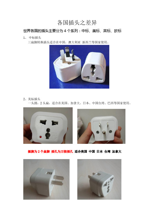
2、美标插头
一头圆,2头扁,适合在美国、加拿大、日本、中国台湾、巴西等国家使用。
插脚为2个扁脚插孔为万能插孔适合美国中国日本台湾加拿大
3、英标插头
适合英国,新西兰,印度,巴基斯坦,香港,澳门,马尔代夫,新加坡,马来西亚,巴林群岛,不丹,文莱,印度尼西亚,不丹,博茨瓦纳,文莱,塞浦路斯,也门,加纳,肯尼亚,卡塔尔,坦桑尼亚,津巴布韦,阿联酋等。
4、欧标插头
适合德国、丹麦、芬兰、法国、挪威、瑞典、荷兰、波兰、葡萄牙、韩国、奥地利、比利时、瑞士、西班牙、匈牙利、捷克、斯洛伐克、俄罗斯、埃及、乌克兰、土耳其、阿联酋、巴西等。
Tripp Lite UT750UL 电源转换器 750W 实用 工作车辆逆变器 双输出说明书
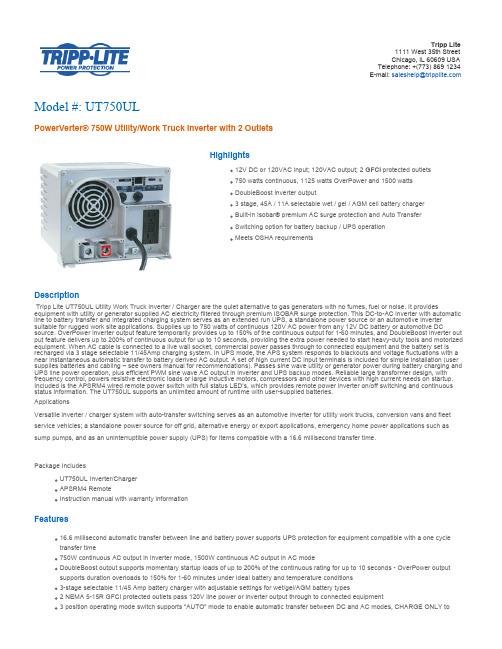
Tripp Lite1111 West 35th StreetChicago, IL 60609 USATelephone: +(773) 869 1234E-mail: ***********************Model #: UT750ULPowerVerter® 750W Utility/Work Truck Inverter with 2 OutletsHighlights12V DC or 120VAC input; 120VAC output; 2 GFCI protected outlets750 watts continuous, 1125 watts OverPower and 1500 wattsDoubleBoost inverter output3 stage, 45A / 11A selectable wet / gel / AGM cell battery chargerBuilt-in Isobar® premium AC surge protection and Auto TransferSwitching option for battery backup / UPS operationMeets OSHA requirementsDescriptionTripp Lite UT750UL Utility Work Truck Inverter / Charger are the quiet alternative to gas generators with no fumes, fuel or noise. It provides equipment with utility or generator supplied AC electricity filtered through premium ISOBAR surge protection. This DC-to-AC inverter with automatic line to battery transfer and integrated charging system serves as an extended run UPS, a standalone power source or an automotive inverter suitable for rugged work site applications. Supplies up to 750 watts of continuous 120V AC power from any 12V DC battery or automotive DC source. OverPower inverter output feature temporarily provides up to 150% of the continuous output for 1-60 minutes, and DoubleBoost inverter out put feature delivers up to 200% of continuous output for up to 10 seconds, providing the extra power needed to start heavy-duty tools and motorized equipment. When AC cable is connected to a live wall socket, commercial power passes through to connected equipment and the battery set is recharged via 3 stage selectable 11/45Amp charging system. In UPS mode, the APS system responds to blackouts and voltage fluctuations with a near instantaneous automatic transfer to battery derived AC output. A set of high current DC input terminals is included for simple installation (user supplies batteries and cabling – see owners manual for recommendations). Passes sine wave utility or generator power during battery charging and UPS line power operation, plus efficient PWM sine wave AC output in inverter and UPS backup modes. Reliable large transformer design, with frequency control, powers resistive electronic loads or large inductive motors, compressors and other devices with high current needs on startup. Included is the APSRM4 wired remote power switch with full status LED’s, which provides remote power inverter on/off switching and continuous status information. The UT750UL supports an unlimited amount of runtime with user-supplied batteries.ApplicationsVersatile inverter / charger system with auto-transfer switching serves as an automotive inverter for utility work trucks, conversion vans and fleet service vehicles; a standalone power source for off grid, alternative energy or export applications, emergency home power applications such as sump pumps, and as an uninterruptible power supply (UPS) for items compatible with a 16.6 millisecond transfer time.Package IncludesUT750UL Inverter/ChargerAPSRM4 RemoteInstruction manual with warranty informationFeatures16.6 millisecond automatic transfer between line and battery power supports UPS protection for equipment compatible with a one cycletransfer time750W continuous AC output in inverter mode, 1500W continuous AC output in AC modeDoubleBoost output supports momentary startup loads of up to 200% of the continuous rating for up to 10 seconds - OverPower output supports duration overloads to 150% for 1-60 minutes under ideal battery and temperature conditions3-stage selectable 11/45 Amp battery charger with adjustable settings for wet/gel/AGM battery types2 NEMA 5-15R GFCI protected outlets pass 120V line power or inverter output through to connected equipment3 position operating mode switch supports “AUTO” mode to enable automatic transfer between DC and AC modes, CHARGE ONLY tomaintain a full battery charge when AC is present without auto transfer and SYSTEM OFF settingsVoltagecompatibility (VDC)12BATTERYExpandable batteryruntimeRuntime is expandable with any number of user supplied wet or gel or AGM type Batteries.DC system voltage(VDC)12Battery PackAccessory (optional)98-121 sealed lead acid battery (optional)Battery recharge rate11A / 45A (selectable)LEDS ALARMS & SWITCHESSwitches 3 position on / off remote switch enables simple on / off power control plus "auto/ remote" Setting that enables distant on / ff control of the inverter system when used in conjunction with APSRM remote (included) when used in invertermode AC uninterruptFront panel LEDs Set of (6) LEDs offer continuous status information on load percentage ( 6 levels reported) and battery charge level(7 levels reported) See manual for sequencesSURGE / NOISE SUPPRESSIONAC suppressionjoule rating450PHYSICALShippingDimensions (HWD/in)12.5 x 11 x 10.75ShippingDimensions(HWD/cm)31.75 x 27.94 x 27.31Shipping weight (lbs)20.6Shipping weight (kg)8.2Unit Dimensions(HWD/in)7 x 8.75 x 9Unit Dimensions(HWD/cm)17.78 x 22.23 x 22.86Unit weight (lbs)17.4Unit weight (kg)7.9Cooling method Multi-speed fanMaterial ofconstructionPolycarbonateReceptacle Color WhiteStyle Heavy-duty with built-in battery chargerForm factors supported Mounting slots enable permanent placement of inverter on any horizontal surface. (see manual for additional mounting information)ENVIRONMENTALRelative Humidity0-95% non-condensing LINE / BATTERY TRANSFERTransfer time from line power to battery mode 16.6 milliseconds (typical -compatible with many computers, servers and networking equipment-verify transfer time compatibility loads for UPS applications)Low voltage transfer to battery power In AC "auto" mode, inverter / charger switches to battery mode as line voltage drops to 75V (user adjustable to 85,95,105 - see manual)High voltage transfer to battery power In AC "auto" mode, inverter / charger switches to battery mode as line voltages increases to 145V (user adjustable to 145 - see manual)SPECIAL FEATURESLoad Sensing Load sense function enables automatic inverter shutoff and startup as connected equipment is powered off and on.Front panel load sense potentiometer can be set to shutoff or turn on inverter power in response to loads of any level. Remote controlcapabilityYesCERTIFICATIONSCertifications Tested to UL 458 (USA) and CSA (Canada)WARRANTYProduct WarrantyPeriod (U.S. &Canada)30-month limited warrantyProduct WarrantyPeriod (International)1-year limited warrantyProduct WarrantyPeriod (Mexico)30-month limited warrantyProduct WarrantyPeriod (Puerto Rico)30-month limited warrantyRelated ItemsOptional ProductsRelated Model Description Qty. APSRM4Remote Control Module - for Tripp Lite Inverters and Inverter/Chargers 1BP-260Ideal battery housing for use with Tripp Lite PowerVerter APS inverter/charger systemswith a 12 or 24V DC system voltage.198-12112V DC Sealed, Maintenance-Free Battery 1More information, including related products, owner's manuals, and additional technical specifications, can be found online at/en/products/model.cfm?txtModelID=3604.Copyright © 2013 Tripp Lite. All rights reserved. All trademarks are the sole property of their respective owners. Tripp Lite has a policy of continuous improvement. Specifications are subject to change without notice. Photos may differ slightly from final products.。
WBT转换插座
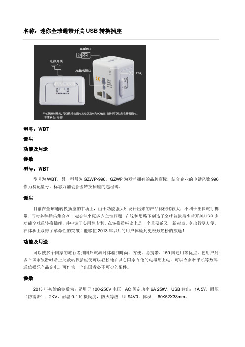
名称:迷你全球通带开关USB转换插座
型号:WBT
诞生
功能及用途
参数
型号:WBT
型号为WBT,另一型号为GZWP-996。
GZWP为万浦拥有的品牌商标,结合企业的电话尾数996作为易记型号。
标志万浦创新型转换插座的起程碑。
诞生
目前在全球通转换插座的市场上,由于功能强大所设计出来的产品休积比较大,不利于出国旅行携带,同时多种插头集合在一起会带来更多安全性问题。
在这种思路下创造了全球首款最小带开关USB多功能全球通转换插座,并申请了实用性专利,在转换插座史上是一个重要的又一新起点。
令出行更方便,在体积上取得了革命性的突破!能够使2013年以后的用户体验到更极致轻松的旅途!
功能及用途
可以使多个国家的旅行者到国外旅游时体验到时尚、方便、易携带、150国通用等优点。
使用户到多个国家旅游时带上此款转换插座便可以轻松地在其它国家令他的电器用上电,可以令多种手机等数码通信娱乐产品充电。
可作为一个出国者必不可少的配件。
参数
2013年初始的参数为:适用于100-250V电压,AC额定功率6A 250V,USB输出:1A 5V。
耐压(防雷击):2KV,耐温0-110摄氏度,防火等级:UL94V0,体积:60X52X38mm。
进展动力电源9100系列电源转换器说明书

PD9100 / 9200 SERIES POWER CONVERTERin material or workmanship under normal use and service; and limits the remedies to repair or This warranty shall extend for a period of two years from the original date of purchase, is valid only within the continental limits of the United States and Canada.WARRANTY EXCLUSIONS: This warranty specifically does not apply to:Any power converter which has been repaired or altered in any way by an unauthorized person orDamage caused by excessive input voltage, misuse, negligence or accident; or an external force;Any power converter which has been connected, installed or adjusted or used other than in accordance the instructions furnished, or has had the serial number altered, defaced or removed;Cost of all services performed in removing and re-installing the power converter; andANY LOST PROFITS, LOST SAVINGS, LOSS OF USE OF ENJOYMENT OR OTHERDAMAGES ARISING OUT OF THE USE OF, OR INABILITY TO USE, THEINCLUDES DAMAGES TO PROPERTY AND, TO THE EXTENT PERMITTED BY LAW, DAMAGES FOR PERSONAL INJURY. THIS WARRANTY IS IN LIEU OF ALL OTHER WARRANTIES, INCLUDING IMPLIED WARRANTIES OFMERCHANTABILITY AND FITNESS FOR A PARTICULAR PURPOSE.PROOF OF PURCHASE: A warranty claim must be accompanied by proof of the date of purchase.CLAIM PROCEDURE: Upon discovery of any defect, Progressive Dynamics, Inc. shall be suppliedthe following information at the address listed below: and address of the claimant;, model and serial number of the power converter;C.Application in which the power converter was installed. (Includes manufacturer,model and model year where applicable)D.Date of purchase; andplete description of the claimed defect.Upon determination that a warranty claimoccurring under normal use and service,)prepaid to Progressive Dynamics, Inc. togetherconverter will be repaired or replaced and returned postage prepaid.Extended warranties areavailable for purchase atINSTALLATION INSTRUCTIONSNOTES:•Horizontal mounting of the power converter, isrecommended although it can be mounted in any position that provides unobstructed ventilation to the fan and vent holes.•The OEM should test the power converter underfull load conditions in its intended mountinglocation. This will insure that there is sufficientunobstructed ventilation to the converterallowing it to operate at its maximum rated load.Failure to provide adequate ventilation to theconverter will cause the converter output to bereduced as it responds to ambient conditions.•The INTELI-POWER converters are notdesigned for zero clearance compartments. •Use a 5/32” hex driver to tighten the outputscrews. Do not exceed 50 in-lbs. torque on the output terminals.•The INTELI-POWER converters are not weather tight or designed for wet mounting locations.They must be protected from direct contact with water.•Avoid the introduction of foreign materials intothe case as this could damage or cause amalfunction of the converter. Installation Steps:1.Secure converter firmly to mounting surface.2.Connect ground lug (found on unit base) tochassis.•Ground wire to be between 6 and 12AWG wire.•Tighten lug to 25 – 35 in-lbs.3.Disconnect battery from both positive (+) andground (-) cables.4.Connect battery ground (-) to converter NEG (-)lug.•Conductor to be between 2 and 14AWG(follow all applicable codes when sizingconductor)•Tighten lug to 30 – 50 in-lbs.5.Disconnect any optional pendants or modules.6.Plug converter into appropriate outlet.ing a DC voltmeter, verify converter output.The power converter is working properly if thevoltage is above 13VDC (12V models), 26VDC(24V models, 14.3VDC (12V 9100L models),and 28.4VDC (24V 9100-24L models). If nooutput is present, refer to the trouble shooting guide in this manual.8.Disconnect power to converter9.Connect battery positive (+) to converter POS (+)lug.•Conductor to be between 2 and 14AWG(follow all applicable codes when sizingconductor)•Tighten lug to 30 – 50 in-lbs.Note: When connecting battery to converterPOS (+), a spark may occur. This is normal. 10.Reconnect battery to both positive (+) and ground(-) cables.11.Reconnect any optional pendants or modules.12.Reconnect power to converter.GENERAL INFORMATIONThe INTELI-POWER series power converters are state-of-the-art electronic converter / battery chargers.Their compact size and quiet operation gives greater flexibility in selecting the mounting location for either OEM installation or after market replacement.All INTELI-POWER series power converters have been designed and tested to provide maintenance free operation and undergone tens of thousands of hours of strenuous engineering testing to ensure years of trouble free operation.The INTELI-POWER 9200 series converter incorporates the Charge Wizard® microprocessor which constantly monitors the battery voltage and automatically adjusts the converter output voltage to provide the proper charging voltage for fast recharges and long-term maintenance.INTELI-POWER 9100 series converters incorporate the Total Charging Management System (TCMS) interface. The TCMS interface connects the converter to optional devices that can automatically control the output voltage of the converter thereby controlling the charge rate to the batteries. (See below for ChargeW izard® functions and performance)INTELI-POWER 9100L series converters do NOT support the Charge Wizard® functionality or provide a TCMS interface. The 9100L series converters incorporate an interface for a remote shutdown module for use with a smart lithium battery system.FEATURESMULTIPLE BATTERY CHARGING... INTELI- POWER converters have the capability of charging multiple batteries at the same time! They can even charge a combination of different capacity batteries. GFCI PROTECTION... INTELI-POWER converters have the LOWEST ground fault leakage. With this unit, the user can confidently utilize theRV's AC outlets without being concerned about a ground fault interruption of the facilities power source.REVERSE BATTERY PROTECTION prevents damage if battery leads are cross connected. Since the only consequence of cross connection is a blown fuse, damage to or possible replacement of the converter is avoided. Cross connection of battery leads is the only thing that will blow these fuses. Replacement fuses are available at any automotive store.CAUTIONIF THE REVERSE BATTERYPROTECTION FUSES ARE BLOWN DURING INSTALLATION, CHECK TOSEE THAT THE BATTERY HAS BEENCONNECTED PROPERLY BEFORE REPLACING THE FUSES. REPLACE THE FUSES ONLY WITH THE SAME TYPE AND RATING AS THE ORIGINAL FUSES. USING OTHER FUSES MAY RESULT IN CONVERTER DAMAGE, VEHICLEDAMAGE, INJURY OR OTHERCONSEQUENCES (SEE WARRANTY). ELECTRONIC CURRENT LIMITING... Should demand exceed the rated capacity of the converter or a short circuit occur, the output voltage of the converter drops to almost zero until the situation is corrected. This feature prevents blown fuses, damage to the converter, 12 volt motors and wiring. AUTOMATIC THERMAL PROTECTION... Should an over temperature condition occur, the converter will reduce power output. The converter automatically resumes normal operation when a safe operating temperature is reached.IGNITION PROTECTION... All INTELI-POWER series converters are ignition protected. VARIABLE SPEED COOLING FAN... An electronic sensor monitors converter temperature. Higher demand generates higher heat, requiring higher fan speeds. Lower demand means lower heat and fan speed. This means the fan may not operate at night or will operate at a very slow, quiet speed when demand is low and the owner is trying to sleep. HIGH VOLTAGE PROTECTION... This circuit shuts the converter down if a surge or spike in input voltage is detected. The converter will automatically return to normal operation when the condition is corrected.LOW VOLTAGE PROTECTION…INTELI-POWER converters automatically shut down if input voltage is insufficient for continued operation. When the low voltage situation is corrected, the INTELI-POWER converter automatically resumes normal operation.GENERAL OPERATIONThe INTELI-POWER series converter will supply "clean" power from input voltages that range from 90-130 VAC (205-265 VAC for 230 volt models). The INTELI-POWER series of converters are primarily designed for use with a battery, however, the output of the INTELI-POWER converters are a regulated, filtered DC voltage that can power sensitive electronics without the need for a battery or other filtering.At normal input voltages the full load rated capacity is available.At input voltages less than 105 VAC (205 VAC for 230 volt models) the converter may not supply full rated output capacity.9100L - The full rated load is available for load, battery charging or both. When functioning as a regulated battery charger the converter has a nominal voltage output of 14.6 VDC for 12 volt models and 29.2 VDC for 24 volt models. The system is designed to sense voltage on the battery and will taper the charging current as the battery becomes charged.CAUTIONThe 9100L series converter/chargers aredesigned to recharge lithium ironphosphate batteries.DO NOT USE TO RECHARGELEAD/ACID BATTERIES!9100 - The full rated load is available for load, battery charging or both. When functioning as a regulated battery charger the converter has a nominal voltage output of 13.6 VDC for 12 volt models and 27.2 VDC for 24 volt models. The system is designed to sense voltage on the battery and will taper the charging current as the battery becomes charged.When the vehicle is to be stored for extended periods of time it is recommended that the batteries be disconnected, unless a TCMS Charge Wizard® is attached to the TCMS interface. Reconnect battery once a month to maintain a full charge. 9200 - The full rated load is available for load, battery charging or both. When functioning as a regulated battery charger the converter has a nominal voltage output of 13.6 VDC for 12 volt models and 27.2 VDC for 24 volt models. The system is designed to sense voltage on the battery and automatically selects one of three operating modes (normal, boost and storage) to provide the correct charge level to the batteries. BOOST MODE: If the converter senses that the battery voltage has dropped below a preset level the output voltage is increased to approximately 14.4 VDC (28.8 VDC for 24 volt models) to rapidly recharge the battery.NORMAL MODE: Output voltage set at approximately 13.6 VDC (27.2 VDC for 24 volt models).STORAGE MODE: When the converter senses that there has been no significant battery usage for 30 hours the output voltage is reduced to 13.2 VDC (26.4 VDC for 24 volt models) for minimal water usage. When in storage mode the microprocessor automatically increases the output voltage to 14.4 VDC (28.8 DC for 24 volt models) for approximately 15 minutes every 21 hours to help prevent sulfation of the battery plates.CAUTIONIT IS IMPORTANT THAT THE FLUIDLEVEL OF ANY CONNECTEDBATTERIES BE CHECKED ON AREGULAR BASIS. ALL BATTERIESWILL “GAS” AND LOSE SOME FLUIDS WHEN CONTINUOUSLY CONNECTED TO ANY CHARGING SOURCECHARGE WIZARD ®… The INTELI-POWER 9200 series converters have the Charge Wizard ® controlledcharging module built in. The Charge Wizard ® is a microprocessor-controlled device incorporated in Progressive Dynamics 9200 Series INTELI-POWER converters which constantly monitors the battery, and automatically adjusts the converter output voltage based on its charge status. The Charge Wizard ® has four (4) operating modes (BOOST, NORMAL, STORAGE and EQUALIZE). Each mode is automatically selected by the Charge Wizard ® and ensures a fast yet safe recharge for your battery. See chart below for details.NOTE: Converter output voltages are 2x the values listed in above table for 24 volt models.Boost Mode (14.4V for 12V models and 28.8V for 24V models) - Boost mode is to rapidly recharge a battery up to 90% of full charge. Required 8 hours to return the battery to 90% of full charge and approximately 11 hours to reach full charge.**Normal Mode (13.6V for 12V models and 27.2V for 24V models) - Normal mode is to safely complete the charge of a battery. Required 40 hours to return the battery to 90% of full charge and approximately 78 hours to reach full charge.**Storage Mode (13.2V for 12V models and 26.4V for 24V models) – Storage mode is to maintain a batteries charge as well as help prevent battery stratification and sulfation. Required 60 hours to return the battery to 90% of full charge and approximately 100 hours to reach full charge.**Equalize Mode (14.4V for 12V models and 28.8V for 24V models) - The Charge Wizard ® will automatically switch to equalize mode for approximately 15 minutes every 21 hours the converter remains in storage mode. This will help prevent battery stratification, sulfation and loss of battery capacity (useful life).** Times based on a PD9155 recharging a 125AH battery that has been discharged to 10.5V.- All times and voltages provided above are approximate. -The integrated Charge Wizard’s ability to change the output voltage of the converter will significantly reduce the amount of time it takes to recharge your battery. The lower voltage for Storage mode helps prevents gassing and reduces water loss during long-term storage.BOOST MODENORMAL MODESTORAGE MODEEQUALIZE MODEOPTIONAL REMOTE PENDANTYour INTELI-POWER 9200 converter may have been supplied with a Remote Pendant. The Remote Pendant is optional on OEM but is included with all retail models and plugs in to the accessory port of the 9200 series converter. While the built-in Charge Wizard® automatically determines which operating mode is best suited to recharge or maintain optimum battery condition, the Remote Pendant allows for manual override and has an indicator light to indicate the mode of operation.BOOST MODE - Indicated by green LED remaining on.NORMAL MODE - When the battery is between 50% and 90% charged, the green LED will flash once per second. When the battery has reached 90% of full charge the green LED will flash 2 - 3 times per second.STORAGE MODE - Indicated by green LED flashing every 6 - 8 seconds.MANUAL BUTTON - The manual button has been provided to allow the operator to temporarily override the converter (not recommended) or to verify the converter is operating properly. For manual operation, press and hold the button. The indicator light will soon remain “ON” indicating Boost Mode. Continue to hold the button and the light will blink rapidly indicating the converter is in the Normal Mode. Continue to hold the button until the light blinks slowly indicating the converter is now in the Storage Mode. After the manual button is released the converter will stay in the selected mode. When the battery charge status changes, the converter will return to the automatic mode of operation to prevent damage to the battery.If a REMOTE PENDANT was not provided with your INTELI-POWER 9200 Series converter, you can purchase one from your local RV dealer or online at OPTIONAL TCMS CHARGE WIZARD Your INTELI-POWER 9100 converter is equipped with a TCMS interface. The TCMS Charge Wizard pendant plugs into the TCMS interface to provide computer control and monitoring of your batteries charge state. The Charge Wizard® automatically determines which operating mode is best suited to recharge or maintain optimum battery condition. The Charge Wizard®Pendant allows for manual override and has an indicator light to indicate the mode of operation.BOOST MODE - Indicated by green LED remaining on.NORMAL MODE - When the battery is between 50% and 90% charged, the green LED will flash once per second. When the battery has reached 90% of full charge the green LED will flash 2 - 3 times per second.STORAGE MODE - Indicated by green LED flashing every 6 - 8 seconds.MANUAL BUTTON - The manual button has been provided to allow the operator to temporarily override the converter (not recommended) or to verify the converter is operating properly. For manual operation, press and hold the button. The indicator light will soon remain “ON” indicating Boost Mode. Continue to hold the button and the light will blink rapidly indicating the converter is in the Normal Mode. Continue to hold the button until the light blinks slowly indicating the converter is now in the Storage Mode. After the manual button is released the converter will stay in the selected mode. When the battery charge status changes, the converter will return to the automatic mode of operation to prevent damage to the battery.The TCMS Charge Wizard Pendant can be purchased from your local RV dealer or online atOPTIONAL REMOTE SHUTDOWN MODULE Your INTELI-POWER 9100L converter is equipped with a Remote Shutdown Module interface. The converter can be shutdown using either a high or low side control, or by connecting two wires by means of a mechanical switch or relay contacts. This allows the battery management system to shutdown the converter after battery charging and balancing are complete.Do not replace the converter unless the following checks have been performed:Loosen the screw on the positive terminal and disconnect the positive wire. Read the converter output voltage using aDC voltmeter. The power converter is working properly if the voltage is above 13VDC (12V models), 26VDC (24V models, 14.3VDC (12V 9100L models), and 28.4VDC (24V 9100-24L models).If the converter output is zero volts, use an AC voltmeter to check for proper voltage at the 120VAC outlet that theconverter is plugged into. This voltage should be between 105 and 130 volts (206 and 265 volts for 230V models). Check the fuses located at the front of the converter. These fuses will only blow if the battery or DC output leadswere connected in reverse, even for a moment. Replace the fuses and repeat step 1.Disconnect optional Remote Pendant, TCMS Charge Wizard, or Remote Shutdown Module. output voltage using a DC voltmeter. The power converter is working properly if the voltage is above 13VDC (12V models), 26VDC (24V models, 14.3VDC (12V 9100L models), and 28.4VDC (24V 9100-24L models). When replacing fuse(s) it may be necessary to remove the TCMS plug or lithium shutdown module (if so equipped)to provide clearance for fuse replacement.Disconnect all power sources before replacing fuses.TROUBLE SHOOTING GUIDEPROBLEMPOSSIBLE CAUSESACTION1. No OutputProper AC power not connected Connect power supplyCheck AC distribution panel for proper operation External Fuses Blown Check for reverse polarityReplace fuses with same type and rating Short CircuitTrace circuits for possible fault Unit has shutdown due to overheating Check air flow Allow unit to cool Unit has shutdown due to over voltage (Also see Item 4 below)(No over voltage protection for 230V units) Check input voltageConverter will shut down if the input voltage exceeds 132 Volts Correct input voltageOptional remote shutdown module is active. (PD9100L only)Remove remote shutdown module.2. External Fuses Blown Reverse Battery Hook Up Correct hook up and replace fuses with same type and rating3. Low OutputExcessive load for converterReduce load requirements or install larger converter Input voltage not between 105-130 VAC (205-265 VAC for 230V units) Correct input supply voltage Bad battery cell(s)Replace battery4. Intermittent or no Output on Generator, works on Shore PowerUnit has shutdown due to over voltage. Add another load to the generator, this may reduce the “spikes” to an acceptable levelSome generators exhibit excessive voltage spikes on the AC power output, this may cause the over voltage protection to shut the unit downContact generator manufacturer for possible defect in the generatorRemote Shutdown Module does not have stable voltage.Confirm Remote Shutdown Module voltage is between 5 and 30 VDCAccessory Port (PD9200only)DC Distribution PanelGrounding Lug (located on AC end) Reverse BatteryFuse(s)-+Chassis Ground BatteryINPUT/OUTPUT S PECIFICATIONS (Specifications subject to change without notice)PD9130(L)Input: 105-130 VAC 60 Hz500 WattsOutput: 13.6 VDC, 30 Amps (9130L) – 14.6 VDC, 30 Amps Dimensions: 4.5H x 8.25L x 7.25WWeight: 4.5lbsPD9140(L)Input: 105-130 VAC 60 Hz600 WattsOutput: 13.6 VDC, 40 Amps (9140L) – 14.6 VDC, 40 Amps Dimensions: 4.5H x 8.25L x 7.25WWeight: 4.5lbsPD9_45(L)Input: 105-130 VAC 60 Hz725 WattsOutput: 13.6 VDC, 45 Amps (9145L) – 14.6 VDC, 45 Amps Dimensions: 4.5H x 8.25L x 7.25WWeight: 4.5lbsPD9_60(L)Input: 105-130 VAC 60 Hz1000 WattsOutput: 13.6 VDC, 60 Amps (9160L) – 14.6 VDC, 60 Amps Dimensions: 3.6H x 8L x 9WWeight: 5.8lbsPD9_70(L)Input: 105-130 VAC 60 Hz1250 WattsOutput: 13.6 VDC, 70 Amps (9170L) – 14.6 VDC, 70 Amps Dimensions: 3.6H x 8L x 9WWeight: 5.8lbsPD9_80A(L)Input: 105-130 VAC 60 Hz1300 WattsOutput: 13.6 VDC, 80 Amps (9180AL) – 14.6 VDC, 80 Amps Dimensions: 3.6H x 8L x 9WWeight: 6.0lbsPD9_25-24(L)Input: 105-130 VAC 60 Hz775 WattsOutput: 27.2 VDC, 25 Amps (9125-24L) – 29.2 VDC, 25 Amps Dimensions: 4.5H x 8.25L x 7.25WWeight: 4.5lbs PD9_40-24A(L)Input: 105-130 VAC 60 Hz1300 WattsOutput: 27.2 VDC, 40 Amps (9140-24AL) – 29.2 VDC, 40 Amps Dimensions: 3.6H x 8L x 9WWeight: 6.0lbsPD9260-230Input: 205-265 VAC 50/60 Hz1000 WattsOutput: 13.6 VDC, 60 Amps Dimensions: 3.6H x 8L x 9WWeight: 5.8lbsNOT UL OR CUL LISTED。
Cobra CPI2500W 专业级电源转换器说明书
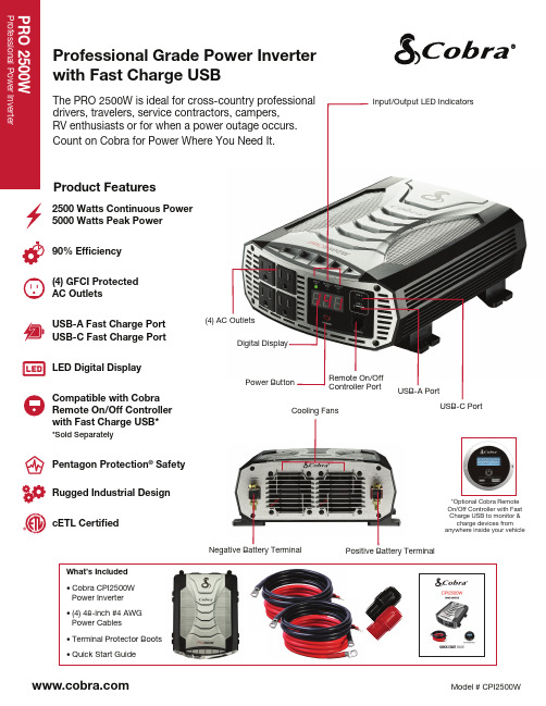
Professional Grade Power Inverter with Fast Charge USBProduct FeaturesThe PRO 2500W is ideal for cross-country professional drivers, travelers, service contractors, campers, RV enthusiasts or for when a power outage occurs. Count on Cobra for Power Where You Need It.What’s Included • Cobra CPI2500WPower Inverter• (4) 48-inch #4 AWGPower Cables• Terminal Protector Boots• Quick Start Guide USB-A Port Digital Display Power Button Negative Battery Terminal(4) AC Outlets Cooling Fans Input/Output LED Indicators USB-C Port Positive Battery TerminalRemote On/OffController Port2500 Watts Continuous Power5000 Watts Peak Power 90% Ef ciency(4) GFCI ProtectedAC OutletsUSB-A Fast Charge PortUSB-C Fast Charge PortLED Digital DisplayCompatible with CobraRemote On/Off Controllerwith Fast Charge USB**Sold Separately Pentagon Protection ® SafetyRugged Industrial DesigncETL Certi ed*Optional Cobra Remote On/Off Controller with Fast Charge USB to monitor & charge devices from anywhere inside your vehicleAppliance WattageReference ChartContinuous Power 2500W Surge Power 5000W Efficiency Rating 90% No-load draw < .6A Output Waveform Modified Sine Wave Input Voltage Range 10 - 15.0V DC Output Voltage Range 115V AC, 60Hz, 21.7A, 2500W Low Voltage Alarm 11.5V DC, 10.5V Selectable Option Low Voltage Cut-Off 10.5V DC, 9.5V DC Selectable Option AC Receptacles 4 GFCI Protected AC Outputs Fast Charge USB-A Output 5V/3.0A, 9V/1.67A Fast Charge Fast Charge USB-C Output 5V/3.0A, 9V/1.67A Fast Charge Remote-Ready Output Port Yes Remote Included* No 12V Vehicle Accessory Cable No Includes Direct-to-Battery Cables Yes Direct-to-Battery Cables 48" #4 AWG Cables. (2) Black, (2) Red) Thermal Shut-Down Yes Reverse Polarity Protection Yes Volt/Watt Meter 7-Segment LED Display Warranty 2 Year Package Type Gift Carton Product Weight 5.73 lbs Product dimensions 3.74" H x 8.94"W x 11.5"D Package dimensions 5.2" H x10.16"W x15.04"D Master pack quantity 2Master pack dimensions 10.87"H x 10.55" W x 15.83" D Master pack weight 17.4 lbs UPC 0 28377 31563 3Master pack barcode 5 00 28377 31563 8General Product Launch Info MS RP/MAP: $299.95Cobra ® and the snake design are registered trademarks of Cobra Electronics Corporation, USA.Cobra Electronics Corporation™ is a trademark of Cobra Electronics Corporation, USA.Other trademarks and trade names are those of their respective owners.*Sold Separately。
马来西亚旅游需要什么样的转换插头

马来西亚旅游需要什么样的转换插头
马来西亚旅游需要什么样的转化插?近年来,马来西亚成为很多国人的出游目的国,旅游人数不断增长,很多人搜索“马来西亚旅游必备”,这时候,你会看到转化插成为很多网友推荐的必备用品。
为什么到马来西亚旅游需要带转化插,马来西亚的插座跟中国有什么不同呢?
今天,广龙五金电器厂的小编为大家解疑。
马来西亚的插头属于英式插头,跟中国的国际标准插头有所不同,英式插头是三个方形的插头。
英国标
准的插头是品字形、矩形柱状,截面大、耐受大电流,是众多插头标准里最安全的插头之一。
英标电源插座
有保护门设计,可以防止异物插入或者防止误插入,更加安全可靠。
今天给大家推荐几款比较好用的马来西亚转化插。
世界各国转换插头标准

国家电压(V) 对应产品(插头)型号备注阿尔巴尼亚220 欧标转换插头 A 阿尔及利亚230 欧标转换插头阿富汗220 欧标转换插头阿根廷220 欧标转换插头阿拉伯联合酋长国220 欧标/英标转换插头阿鲁巴岛127 美标转换插头阿曼240 欧标转换插头埃及220 欧标转换插头埃塞俄比亚230 瑞士转换插头爱尔兰230 欧标转换插头爱沙尼亚230 欧标转换插头安哥拉220 欧标转换插头安圭拉岛110 日本转换插头安提瓜岛230 美标转换插头奥地利230 欧标转换插头澳大利亚230 国标转换插头巴巴多斯岛115 美标转换插头 B 巴布亚新几内亚240 国标转换插头巴哈马群岛120 美标转换插头巴基斯坦230 英标转换插头巴拉圭220 欧标转换插头巴利阿里群岛220 欧标转换插头巴林群岛230 英标转换插头巴拿马110 美标转换插头巴西220 美标转换插头百慕大群岛120 美标转换插头保加利亚230 欧标转换插头贝宁湾220 欧标转换插头比利时230 欧标转换插头冰岛220 欧标转换插头波多黎各120 美标转换插头波兰220 欧标转换插头波斯尼亚220 欧标转换插头玻利维亚220 欧标转换插头伯利兹城220 美标转换插头博茨瓦纳231 英标转换插头不丹230 英标转换插头布基纳法索220 欧标转换插头布隆迪220 欧标转换插头赤道几内亚220 欧标转换插头 C 丹麦220 欧标转换插头 D 德国230 欧标转换插头东帝汶220 欧标转换插头多哥220 欧标转换插头多米尼加230 英标转换插头多米尼加共和国110 日本转换插头俄罗斯220 欧标转换插头 E 厄瓜多尔120 美标转换插头厄立特里亚230 欧标转换插头法国230 欧标转换插头 F 法罗群岛220 欧标转换插头菲律宾220 美标转换插头斐济240 国标转换插头芬兰230 欧标转换插头佛得角220 欧标转换插头福克兰群岛240冈比亚230 英标转换插头 G 刚果230 欧标转换插头哥伦比亚110 美标转换插头哥斯达黎加120 美标转换插头格林纳达230 英标转换插头格陵兰220 欧标转换插头古巴110/220 欧标转换插头瓜德罗普岛230 欧标转换插头关岛120 美标转换插头圭亚那240 美标转换插头哈萨克斯坦220 欧标转换插头H 海地110 美标转换插头韩国220 欧标转换插头荷兰230 欧标转换插头洪都拉斯110 美标转换插头怀特岛240 欧标转换插头J 基里巴斯240 欧标转换插头吉布提220 欧标转换插头几内亚220 欧标转换插头几内亚比绍共和国220 欧标转换插头加拿大120 美标转换插头加纳230 英标转换插头加蓬220 欧标转换插头加沙230柬埔寨230 欧标转换插头 K 捷克斯洛伐克230 欧标转换插头津巴布韦220 英标转换插头喀麦隆220 欧标转换插头卡塔尔240 英标转换插头开曼群岛120 美标转换插头科摩罗220 欧标转换插头科威特240 欧标转换插头克罗地亚230 欧标转换插头肯尼亚240 英标转换插头拉脱维亚220 欧标转换插头 L 莱索托220老挝国230 美标转换插头黎巴嫩230 美标转换插头立陶宛220 欧标转换插头利比里亚120 美标转换插头利比亚127列支敦士登的230 瑞士转换插头卢森堡220 欧标转换插头卢旺达230 欧标转换插头罗马尼亚230 欧标转换插头马达加斯加岛220 欧标转换插头 M 马尔代夫230 英标转换插头马耳他240 英标转换插头马拉维230 英标转换插头马来群岛240 英标转换插头马里220 欧标转换插头马其顿王国220 欧标转换插头马提尼克岛220 欧标转换插头毛里求斯230 欧标转换插头毛利塔尼亚220 欧标转换插头美国120 美标转换插头蒙古230 欧标转换插头蒙特塞拉特岛230 美标转换插头孟加拉国220 欧标转换插头秘鲁220 美标转换插头密克罗尼西亚120 美标转换插头缅甸230 欧标转换插头摩洛哥220 欧标转换插头摩纳哥220 欧标转换插头莫桑比克220 欧标转换插头墨西哥127 美标转换插头纳米比亚220 N南非220/230 南非转换插头南斯拉夫220 欧标转换插头瑙鲁240 国标转换插头尼加拉瓜120 日本转换插头尼日尔220 欧标转换插头尼日利亚240 美标/英标转换插头挪威220 欧标转换插头葡萄牙220 欧标转换插头P日本100 日本插头转换插头R瑞典220 欧标转换插头瑞士230 瑞士转换插头萨尔瓦多120 美标转换插头S萨摩亚群岛120 欧标转换插头塞尔维亚230 欧标转换插头塞拉利昂230 美标/英标转换插头塞内加尔230 欧标转换插头塞浦路斯240 英标转换插头塞舌尔240 英标转换插头沙特阿拉伯127/220 美标/欧标/英标转换插头圣路易斯230 英标转换插头斯里兰卡230斯洛伐克230 欧标转换插头斯洛文尼亚220 欧标转换插头斯威士兰230苏丹230 欧标转换插头索马里220 欧标转换插头塔吉克斯坦220 欧标转换插头T塔希提岛110/220 欧标转换插头泰国220 欧标转换插头台湾110 美标转换插头坦桑尼亚230 英标转换插头汤加240突尼斯220 欧标转换插头土耳其230 欧标转换插头土库曼斯坦220 美标转换插头危地马拉120 美标转换插头W 委内瑞拉120 美标转换插头文莱240 英标转换插头乌干达240 英标转换插头乌克兰220 欧标转换插头乌拉圭220 欧标转换插头乌兹别克斯坦220 欧标转换插头西班牙230 欧标转换插头X 西萨摩亚230希腊220 欧标转换插头香港200/220 英标转换插头象牙海岸220 欧标转换插头新加坡230 英标转换插头新喀里多尼亚220 欧标转换插头新西兰230 国标转换插头匈牙利230 欧标转换插头叙利亚220 欧标转换插头牙买加110 美标转换插头Y亚美尼亚220 欧标转换插头亚述尔群岛220 欧标转换插头也门220 英标转换插头伊拉克230 欧标转换插头伊朗230 欧标转换插头以色列230 欧标转换插头意大利230 意标转换插头印度240 英标转换插头印度尼西亚127/240 欧标转换插头英国230/240 英标转换插头约旦230 欧标转换插头越南127/220 欧标/英标转换插头赞比亚230 欧标转换插头Z 乍得湖220 欧标转换插头直布罗陀230 欧标转换插头智利220 意标转换插头中非共和国220 欧标转换插头中国220 国标转换插头A澳大利亚插头 230 澳洲转换插头阿富汗插头 220 德国/法国转换插头阿根廷插头 220 德国/法国转换插头阿拉伯联合酋长国插头 220 欧洲/英国转换插头埃及插头 220 德国/法国转换插头埃塞俄比亚插头 230 瑞士转换插头爱尔兰插头 230 德国/法国转换插头安哥拉插头 220 德国/法国转换插头安圭拉岛插头 110 日本转换插头安提瓜岛插头 230 美国转换插头奥地利插头 230 德国/法国转换插头B巴巴多斯岛插头 115 美国转换插头巴布亚新几内亚插头 240 国标/澳洲转换插头巴哈马群岛插头 120 美国转换插头巴基斯坦插头 230 英国转换插头巴拉圭插头 220 德国/法国转换插头巴利阿里群岛插头 220 德国/法国转换插头巴林群岛插头 230 英国转换插头巴拿马插头 110 美国转换插头巴西插头 220 美国转换插头百慕大群岛插头 120 美国转换插头比利时插头 230 德国/法国转换插头冰岛插头 220 德国/法国转换插头波多黎各插头 120 美国转换插头波兰插头 220 德国/法国转换插头波斯尼亚插头 220 德国/法国转换插头玻利维亚插头 220 德国/法国转换插头伯利兹城插头 220 美国转换插头博茨瓦纳插头 231 英国转换插头D丹麦插头 220 德国/法国转换插头德国插头 230 德国/法国转换插头东帝汶插头 220 德国/法国转换插头多哥插头 220 德国/法国转换插头多米尼加插头 230 英国转换插头多米尼加共和国插头 110 日本转换插头E俄罗斯插头 220 德国/法国转换插头厄瓜多尔插头 120 美国转换插头厄立特里亚插头 230 德国/法国转换插头F法国插头 230 德国/法国转换插头法罗群岛插头 220 德国/法国转换插头菲律宾插头 220 美国转换插头芬兰插头 230 德国/法国转换插头佛得角插头 220 德国/法国转换插头福克兰群岛插头 240G刚果插头 230 德国/法国转换插头哥伦比亚插头 110 美国转换插头哥斯达黎加插头 120 美国转换插头古巴插头 110/220 德国/法国转换插头瓜德罗普岛插头 230 德国/法国转换插头关岛插头 120 美国转换插头圭亚那插头 240 美国转换插头H哈萨克斯坦插头 220 德国/法国转换插头海地插头 110 美国转换插头韩国插头 220 德国/法国转换插头荷兰插头 230 德国/法国转换插头洪都拉斯插头 110 美国转换插头怀特岛插头 240 德国/法国转换插头J加拿大插头 120 美国转换插头加纳插头 230 英国转换插头加蓬插头 220 欧洲转换插头加沙插头 230柬埔寨插头 230 德国/法国转换插头K捷克斯洛伐克插头 230 德国/法国转换插头津巴布韦插头 220 英国转换插头喀麦隆插头 220 德国/法国转换插头卡塔尔插头 240 英国转换插头开曼群岛插头 120 美国转换插头科摩罗插头 220 德国/法国转换插头科威特插头 240 德国/法国转换插头克罗地亚插头 230 德国/法国转换插头肯尼亚插头 240 英国转换插头拉脱维亚插头 220 德国/法国转换插头L莱索托插头 220老挝国插头 230 美国转换插头黎巴嫩插头 230 美国转换插头立陶宛插头 220 德国/法国转换插头利比里亚插头 120 美国转换插头利比亚插头 127列支敦士登的插头 230 瑞士转换插头卢森堡插头 220 德国/法国转换插头卢旺达插头 230 德国/法国转换插头罗马尼亚插头 230 德国/法国转换插头马达加斯加岛插头 220 德国/法国转换插头M马耳他插头 240 英国转换插头马拉维插头 230 英国转换插头马来群岛插头 240 英国转换插头马里插头 220 德国/法国转换插头马其顿王国插头 220 德国/法国转换插头马提尼克岛插头 220 德国/法国转换插头毛里求斯插头 230 德国/法国转换插头毛利塔尼亚插头 220 德国/法国转换插头美国插头 120 美国转换插头蒙古插头 230 德国/法国转换插头蒙特塞拉特岛插头 230 美国转换插头孟加拉国插头 220 德国/法国转换插头秘鲁插头 220 美国转换插头密克罗尼西亚插头 120 美国转换插头缅甸插头 230 德国/法国转换插头摩洛哥插头 220 德国/法国转换插头摩纳哥插头 220 德国/法国转换插头莫桑比克插头 220 德国/法国转换插头墨西哥插头 127 美国转换插头纳米比亚插头 220N南非插头 220/230 南非转换插头南斯拉夫插头 220 德国/法国转换插头尼加拉瓜插头 120 日本转换插头尼日尔插头 220 德国/法国转换插头尼日利亚插头 240 美国/英标转换插头挪威插头 220 德国/法国转换插头P葡萄牙插头 220 德国/法国转换插头R日本插头 100 日本转换插头瑞典插头 220 德国/法国转换插头瑞士插头 230 瑞士转换插头塞浦路斯插头 240 英国转换插头塞舌尔插头 240 英国转换插头沙特阿拉伯插头 127/220 美国/欧洲/英国转换插头圣路易斯插头 230 英国转换插头斯里兰卡插头 230斯洛伐克插头 230 德国/法国转换插头斯洛文尼亚插头 220 德国/法国转换插头斯威士兰插头 230苏丹插头 230 德国/法国转换插头索马里插头 220W乌干达插头 240 英国转换插头乌拉圭插头 220 德国/法国转换插头乌兹别克斯坦插头 220 德国/法国转换插头西班牙插头 230 德国/法国转换插头X西萨摩亚插头 230希腊插头 220 德国/法国转换插头香港插头 200/220 英国转换插头象牙海岸插头 220 德国/法国转换插头新加坡插头 230 英国转换插头新喀里多尼亚插头 220 德国/法国转换插头新西兰插头 230 国标/澳洲转换插头匈牙利插头 230 德国/法国转换插头叙利亚插头 220 德国/法国转换插头Y牙买加插头 110 美国转换插头亚美尼亚插头 220 德国/法国转换插头亚述尔群岛插头 220 德国/法国转换插头也门插头 220 英国转换插头伊拉克插头 230 德国/法国转换插头伊朗插头 230 德国/法国转换插头以色列插头 230 德国/法国转换插头意大利插头 230 意大利转换插头印度插头 240 英国转换插头印度尼西亚插头 127/240 德国/法国转换插头英国插头 230/240 英标转换插头约旦插头 230 德国/法国转换插头越南插头 127/220 欧标/英标转换插头Z赞比亚插头 230 德国/法国转换插头乍得湖插头 220 德国/法国转换插头直布罗陀插头 230 德国/法国转换插头智利插头 220 意大利转换插头中国插头 220 国标/澳洲转换插头中非共和国插头 220 德国/法国转换插头(注:素材和资料部分来自网络,供参考。
美国特产公司高速手机干燥器(220-240V)型号:0197-2-92 产品介绍说明书
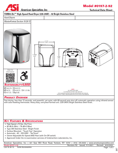
Scan forInformationP roduct o verviewFast drying, less than 12 seconds, and powerful, yet quiet, with 60-second auto shut off; automatic operation using infrared sensor with auto-resetting thermostat. Heavy-duty, one-piece-formed unit. (220-240V) Bright Stainless Steel finish.K ey F eatures & s PeciFications• High Speed <15 Sec. Dry T ime • 65 dB-A (Min) / 78 dB-A (Max)American Specialties, Inc. | 441 Saw Mill River Road, Yonkers, NY 10701 | (914) 476-9000 | Model:#0197-2-92Issued:11/1/2021Revised:8/22/2023Page:1 of 2Revision :R2s ustainability /leedTURBO-Dri™ High-Speed Hand Dryer (220-240V) – 92 Bright Stainless Steel287Toilet Accessories CSI:10 28 13MR 4.2 (1) MR 6 (1) EQ 4.1 (1) EQ 4.2 (1)EQ 4.4 (1) EAp2 (0)EA 1 (1-19)o Peration & M aintenancet echnical i nForMation / P roduct P roPertiesi nstallationo Ptionsw arrantySurface mount unit on wall with four (4) 1/4" [6] washers and screws or bolts (not supplied) through holes (provided) in a corrosion protected steel back plate into suitable prepared mountings (by others) or other suitable mounting hardware (by others) to suit wall conditions. Electrical service is supplied and connected (by others) prior to installing cover. Cover is secured to back plate with recessed, pin-hex socket head cap screws (supplied). For compliance with ICC/ANSI A-117.1- 2003 and 2010 ADA Accessibility Standards for adults, install unit with bottom of sensor lens 48" [1219] maximum Above Finished Floor (AFF) if unobstructed reach access is provided or 44" [1118] max AFF if forward reach over an obstruction (e.g. vanity or commode) with reach depth greater than 20" [508] and less than 25" [635] is only provided. For general utility, install unit so that sensor lens is 44" [1118] to 54" [1372] AFF . See OM and T emplate MT & IG supplied with unit.Voltage0197-2-92: 208-240 VAC - 50/60 Hz - 7.3 A (Max.) - 1400-1700W 0197-1-92: 110-120 VAC - 50/60 Hz - 14.6 A (Max.) - 1300-1600WMotorHPRPM (x1000)Fan T ypeAirflowHeating Element Air Output T emperature TimingDrying Time Brush T ype Dual Ball Bearings17-18 (Adj.)Multi-Inlet Centrifugal 63.6 CFM (108 m3/h)Nichrome wire with auto reset circuit breaker140o F ± 5 @ 77o F (60o C ± 2.4 @ 25o C) Ambient roomtempAutomatic 60 second Shut-OffLess Than 15 SecondsManufacturer reserves the right to make changes to the design, dimensions or functionality of the product without formal notice.Automatic "No-Touch"Activate dryer by placing hands under sensor. LED in sensor array shines blue light during operation to guide user to optimal hand placement for shorter drying time. Dryer automatically shuts off after user removes hands from sensor zone.Five (5) Y ears from date of InvoiceAmerican Specialties, Inc. | 441 Saw Mill River Road, Yonkers, NY 10701 | (914) 476-9000 | Model:CSI:#0197-2-9210 28 13Toilet Accessories Issued:11/1/2021Revised:8/22/2023Page:Revision :Type 304 Stainless Steel - Bright Finish 208-240V AC PropertyValueDimensions Construction 8-1/16" x 11-19/64" x 7-5/64" [205 x 287 x 180]Surface Mounted - "Touch Free" Operation 2 of 2R2Mounting Electrical。
杰弗逊电器 SA-OWSP60 6口旋转插座防雷保护器说明书

When the LED INDICATOR no longer lights up, the surge protection has been exhausted and it’s time to replace the u nit!CAUTION!: Avoid potential personal injuries and property damage!• To Reduce the Risk of Electric Shock - Use Only in Dry Locations, Indoors!• Ensure all of your external connections, including Satellite/Cable TV (Coax) and Phone/Ethernet (RJ45), are protected if applicable. Transient lines connected directly to your equipment without first passing through a surge protector are at risk of damage and are not covered by the connected equipment warranty.• Due to the sacrificial properties of the internal MOV’s it is recommended that the surge protector be checked after lightning storms to verify the surge protection was not consumed.• The input plug of this power tap is intended to serve as the disconnect device, it shall be easily accessible and withdrawn.• This power center does not contain internal circuit breaker protection. INSTALLER MUST ensure that the input of this power center is connected individually to an electrical service panel that is protected with a UL Listed 20A (Maximum) circuit breaker for overload protection of the power center.• Not designed for use with receptacles with indicator lights or controls as this unit will cover them.• To reduce the risk of fire or electric shock, do not use this device with a receptacle in which the slot openings to not align with the blades.• All accessories must be grounded.• Circuit Overloading - Consideration should be given to the connection of the equipment to the supply circuit and the effect that overloading of the circuits might have on overcurrent protection and supply wiring. Appropriate consideration of equipment nameplate ratings should be used when addressing this concern.• Surge protector must be plugged directly to the power source and must not be "daisy-chained" together (in serial) with other power strips, surge protectors or extension cords.• Do not use this product for any purpose not explicitly specified by manufacturer.• If you do not understand these instructions, or have doubts about the safety of the installation, assembly or use of this product, contact Customer Service or call a qualified contractor.• Do not disassemble the surge protector. Disassembling will void the warranty and may cause serious personal injury.• Manufacturer is not responsible for damage or injury caused by incorrect assembly or use.LEGRAND LIMITED WARRANTY AND CONNECTED EQUIPMENT DAMAGE LIMITED WARRANTYProduct WarrantyLegrand warrants to the original purchaser that the product shall be free of defects in materials and workmanship under normal use for five (5) years. When this surge protector operates properly and prevents an energy surge from damaging electrical equipment, the surge protective component will disconnect from the circuit and you will need to buy a replacement product. This warranty extends only to the original purchaser and is nontransferable during the warranty period. Legrand will, at no additional charge, repair or replace defective parts or, at its option, replace the entire unit. This warranty does not extend to any Legrand product that has been damaged or rendered inoperable as intended or defective (a) as a result of accident, misuse or abuse; or (b) by the use of parts not manufactured or sold by Legrand; or (c) by modification of the product.Connected Equipment Damage Limited WarrantyLegrand will also provide you with a remedy for damage to connected equipment if (i) you have a claim that is covered by the limited product warranty described above, and (ii) Legrand receives a formal warranty claim from you before the end of the warranty period for damage to connected applicable to the affected product. If the conditions listed in the preceding sentence are met, Legrand will provide you with one of the following remedies, provided that it may decide at its sole discretion which remedy it provides. Legrand will (1) replace the damaged connected equipment; (2) pay to repair the damaged connected equipment; or (3) pay you the fair market value of the connected equipment, provided that such payments shall not exceed (i) the maximum coverage amount for the product, or (ii) the amount of actual damage caused by power surges due to a product defect. NOTE: Compensation for restoration of data loss is not covered AND LEGRAND DOES NOT ASSUME ANY LIABILITY FOR ANY LOSS OF PROFIT , REVENUE OR SAVING (WHETHER DIRECT OR INDIRECT) OR FOR ANY INCIDENT AL, CONSEQUENTIAL OR INDIRECT DAMAGES UNDER THIS LIMITED WARRANTY . Protection for Network/T elephone (RJ45) or Cable/Satellite TV (CA TV Coax) transient lines only applies to Legrand products which offer such protection, and in such cases, the connections must be properly installed and CA TV service must be grounded properly according to codes set forth in the National Electric Code (NEC) in order to be covered. Some states do not allow the exclusion or limitation of incidental or consequential damages, so the above limitation or exclusion may not apply to you. THE MAXIMUM AMOUNT OF COVERAGE FOR DAMAGE TO PROPERLY CONNECTED EQUIPMENT IS $25,000. Nothing in this warranty shall exclude or limit liability for death or personal injury caused by negligence, for fraud or fraudulent misrepresentation or where exclusion or limitation is not permitted by law.Other Rights. THESE LIMITED WARRANTIES GIVE YOU SPECIFIC LEGAL RIGHTS, AND YOU MAY ALSO HAVE OTHER RIGHTS. THIS WARRANTY DOES NOT AFFECT YOUR STATUTORY RIGHTS. THIS WARRAN TY EXTEN DS ON LY TO YOU, THE ORIGIN AL PURCHASER, AN D CAN N OT BE TRAN SFERRED OR ASSIGN ED. If any provision of these limited warranties is unlawful, void or unenforceable, that provision shall be deemed severable and shall not affect any remaining provisions. In case of any inconsistency between the English and other versions of these limited warranties, the English version shall prevail.Registration. Please register your Product at . Failure to register does not affect your warranty rights.FORMAL WARRANTY CLAIMHow To Make A Claim. In the event damage has occurred to a Legrand product or to connected equipment, you must contact Legrand within thirty (30) days of the date you knew or should have known of the damages. Follow all instructions for making a claim. THIS REQUIREMENT THAT YOU NOTIFY LEGRAND WITHIN THIRTY (30) DAYS AFTER YOU DISCOVER OR SHOULD HAVE DISCOVERED A PRODUCT DEFECT AFFECTS AND LIMITS YOUR WARRANTY RIGHTS.GENERAL PROVISIONSChoice of Law/Jurisdiction. These limited warranties and any disputes arising out of or in connection with these limited warranties (“Disputes”) shall be governed by the laws of England and Wales, excluding the Convention for the International Sale of Goods. The courts located in England and Wales shall have exclusive jurisdiction over any Disputes.TO THE MAXIMUM EXTENT PERMITTED BY LAW THESE LIMITED WARRANTIES ARE IN LIEU OF AND IN PLACE OF ALL OTHER EXPRESS OR IMPLIED WARRANTIES, CONDITIONS AND OTHER TERMS.Legrand AV Inc. and its affiliated corporations and subsidiaries (collectively, “Legrand”), intend to make this manual accurate and complete. However, Legrand makes no claim that the information contained herein covers all details,conditions, or variations. Nor does it provide for every possible contingency in connection with the installation or use of this product. T he information contained in this document is subject to change without notice or obligation of any kind. Legrand makes no representation of warranty, expressed or implied, regarding the information contained herein. Legrand assumes no responsibility for accuracy, completeness or sufficiency of the information contained in this document.©2021 Legrand AV Inc. All Rights Reserved. SANUS is a Legrand AV Inc. brand. SANUS and the SANUS logo are trademarks of Legrand.Legrand A V Inc. • 6436 City West Parkway • Eden Prairie, MN 55344 USAWe’ll Make It Stress-FreeIf you have any questions, just give us a call.800-359-5520。
国际旅行中如何解决电源插头线的兼容性问题

国际旅行中如何解决电源插头线的兼容性问题在国际旅行中,每个旅行者都会遇到电源插头线的兼容性问题,因为不同国家和地区使用的电源插座类型和电压标准可能不同。
这意味着你的电子设备在不同国家的插座上可能无法充电或使用。
为了解决这个问题,有几种方法可以帮助你在国际旅行中解决电源插头线的兼容性问题。
1.购买一个全球通用适配器全球通用适配器是一种能够适应不同国家和地区插座类型的装置。
它通常具有可调节的插座和可更换的插头,因此你可以根据所需的插座类型进行调整并适应当地电源插座。
这种适配器通常带有不同的插头类型和地区的标记,以帮助你方便地选择适当的插头。
购买一个全球通用适配器可以让你的电子设备在多个国家的插座上使用,使你的旅行更加便利。
2.购买国际充电器国际充电器是一种适用于多个国家和地区的充电器,它通常具有可更换的插头和适应不同电压的功能。
这种充电器可以根据你所在的国家或地区进行电压调整,以确保你的电子设备得到正确的电源供应。
购买一个国际充电器可能比全球通用适配器更加方便,因为你只需更换充电头就可以解决兼容性问题。
3.租用或借用当地充电器在一些旅游热门的国家或地区,你可以选择租用充电器或向酒店前台借用充电器。
这种方法适用于那些只在短时间内旅行的人,或者对购买适配器或充电器不感兴趣的人。
在前往目的地之前,你可以进行一些调查,以了解当地是否提供这种服务,以及租用或借用的费用和流程。
4.考虑使用USB充电现代的电子设备大多数都可以通过USB接口进行充电,这为你的国际旅行提供了更多的便利。
你可以考虑购买一个带有USB充电功能的移动电源,这样你可以通过USB线缆来充电你的设备。
大多数国家都提供标准的USB插口,这意味着你可以在不同国家使用相同的充电方法,而不必担心插座的兼容性问题。
5.事先了解目的地的电源插座类型以及电压标准在你计划国际旅行之前,了解目的地的电源插座类型和电压标准非常重要。
这将帮助你更好地准备适配器或充电器,并避免在旅行中遇到不必要的麻烦。
IOTA DLS系列电源转换器 电池充电器48伏特 Owner’s Manual
AND OPERATING THE UNIT.MOUNTING LOCATIONThe IOTA Power Converter/Battery Charger can be mounted in any position within an enclosed or interior compartment. Provide sufficient air space to allow unrestricted airflow in and around the unit. Provide at least 4″ around the fan of the DLS to allow for proper air intake.DO NOT mount the unit in a zero clearance compartment. DO NOT mount the DLS in the same compartment with flammable items such as gasoline or batteries. There are no components within the DLS unit that, during normal operation, produce arcs or sparks. However, all elec-tronic devices have some potential for generating sparks in the event of failure which can result in explosion or fire. DO NOT mount the DLS in an area that has the potential of dust, debris, or other foreign materials to enter in through the DLS vents. DO NOT place the DLS directly above the battery; the gases from the battery can corrode and damage the DLS.120 VOLT A.C. INPUTPlug the unit A.C. input cord into an appropriate 120-volt 3-wire grounded source. Refer to Illustration 2 for specifications of the cord provided with your DLS unit. See the T echnical Specifica -tions Chart on page 4 for maximum current draw and required input voltages.DO NOT USE EXTENSION CORDS - Using an improper extension cord could result in a risk of fire and electric shock, and may result in property damage, personal injury or death.DO NOT OPERATE THE DLS WITH A DAMAGED CORD OR PLUG. Have the cord or plug replaced immediately by qualified service personnel.To minimize the possibility of arcing at the battery, connect the IOTA power cord to the A C input BEFORE connecting the battery. Note: occasionally a small spark or arc may occur at the power outlet as the unit is plugged in. This is a common occurrence due to the internal capacitors drawing power.BATTERY CONNECTIONDisconnect the positive side of the battery before installation. Connect the positive (red) and negative (black) terminal lugs to battery or load (lugs require a #2 square drive ). Always use the proper size wire based on the amperage of the converter and the battery. When connecting to a battery, a breaker should be installed within 18″ of the battery, connecting the battery posi-tive to the line side of the breaker, and the IOTA unit to the load side. Connect “Chassis Bonding Lug” on the IOTA unit to vehicle chassis or other grounding source. Refer to Illustration 1.REVERSE POLARITY FUSESThe IOTA Battery Charger/Power Supply is protected against reverse polarity on the DC output. If a battery or the unit is hooked up incorrectly, the fuses will blow and can be easily replaced. Always use the same size and style fuse that came with the converter. To change the fuses, use a screwdriver to loosen the screws and remove the fuses. Always replace the fuses with the same type and rating. After inserting the new fuses, tighten the screws firmly. Apply 5 inch-pound maximum torque. DO NOT OVERTIGHTEN. Note: some DLS models require only one fuse. For these units, a small fiberglass spacer may be used in the empty fuse slot to aid with tightening.IOTA DLS-48-20 Power Converter and DLS-54-13 Battery Chargers convert 120 volts nominal A.C. to volts D.C. As a power supply, the DLS-48-20’s tightly controlled regulation allows the user to operate any 12 volt nominal D.C. load up to the converter’s rated output current. As a battery char-ger, the DLS-54-13 will maintain the battery, delivering its full-rated current when the battery capacity falls sufficiently low. The voltage is set to deliver its maximum current for the necessary period of time that minimizes undue stress to the battery caused by heating of its cells. This helps to ensure the longest possible life of the battery. Over time, as the battery nears its full capacity, the converter will float-charge the battery to prevent self-discharge of its cells.The IOTA Power Converters/Battery Chargers are designed with high quality components to help ensure years of continuous use. The unit is protected by multiple protection features for a long, trouble-free life.1) Reverse Battery Polarity Protection. 2) Brown-Out In-put Protection. 3) Over-Current Protection - cycle by cycle peak limiting as well as rated current limiting to maximize the life of the converter. 4) Over-Temperature Protection. In addition, it is designed with a unique “proportional” fan control circuit. Fan speed is directly proportional to the converter’s internal ambient temperature. This enables the fan to turn on and off very slowly, minimizing unwanted fan-starting noise.The IOTA Power Converters/Battery Chargers are war-ranted from defects in materials or workmanship for two years from date of retail purchase, and limits the remedies to repair or replacement. This warranty is valid only in the continental United States and Canada. For com-plete warranty details, contact Customer Service or visit .TWO-STEP VOLTAGE JACKThe two-step voltage jack of the DLS-54-13 allows switching from a long-term float voltage of 54.4vdc to a ‘high-stage’ voltage of 56.8vdc. When the included dual voltage plug is inserted in the jack*, the voltage rises to 56.8vdc for occasional fast charging. When the plug is removed, the voltage drops to 54.4vdc to reduce battery water loss. WARNING: To avoid battery damage, re-move the Dual Voltage Plug when quick-charging is complete. NOTE: If the unit is equipped with an internal IQ4 smart charger, two-step charging is not needed and the Dual Voltage Jack is disabled.CHARGE CONTROL FOR THE DLS-54-13THE IQ4 LED INDICATOR(ONLY ON IOTA MODELS WITH INTERNAL IQ4)IOTA Models with an internal IQ4 smart-charger give the user the benefit of automatic Bulk, Absorption, and Float stage charging. This increases the charging capacity of the IOTA charger, de-creases charge times and insures proper and safe battery charg-ing without over-charging. The LED on the fan end of the unit will indicate which charging phase the IOTA unit is currently in. When the unit is first activated, the LED will flash as it reads the number of cells in the battery. The unit will then proceed directly to the Bulk charging or Float charging phase depending on the charge status of the battery. Current DLS models utilize a three-color LED while earlier models feature a single-color green LED. Refer-ence the appropriate LED CODE TABLES below for the LED codes pertaining to your particular unit. Units that do not have an internal IQ4 smart-charger can easily install an external IQ4 that plugs into the available Dual Voltage Jack. Contact CustomerService for more information.intervals are 0.5 SEC on / 0.5 SEC off.Distributed By:68357-036 REV 2110IOTA ENGINEERING PO BOX 11846 TUCSON, AZ 85734 TEL: 1-800-866-IOTA (4682) FAX: (520) 741-2837 WEB: DLS 54V 13A*DLS 48V 20A*SERIES MRATINGS AND SPECIFICATIONS **Primary to Chassis/Primary to Secondary/Secondary to Chassis*Unit is not UL Listed。
插座的转换头的作用有哪些

插座的转换头的作用有哪些
首先,插座的转换头可以解决国际旅行中的电源适配问题。
由于世界各国的电压和插座标准不尽相同,因此在国际旅行时,我们经常会遇到无法充电或使用电器的问题。
而有了插座的转换头,我们就可以将自己国家的插头转换成目的地国家的插头,从而可以在任何地方使用自己的电器,避免了因电源不匹配而无法使用电器的尴尬情况。
其次,插座的转换头也可以解决国内不同地区的插座标准不一致的问题。
在国内旅行或者搬家时,我们经常会遇到不同地区的插座标准不同的情况,有了插座的转换头,我们就可以轻松解决这个问题,无论是北方的三孔插座还是南方的两孔插座,都可以通过转换头来适配,方便我们的使用。
除了在旅行和搬家时使用,插座的转换头在家庭、办公室和商业场所等各种场合中也有着广泛的应用。
比如在家庭中,如果家里有老人或者小孩,他们可能会使用一些特殊的电器,而这些电器的插头可能与家里的插座不匹配,这时候就可以通过插座的转换头来解决这个问题。
在办公室和商业场所中,由于设备和电器种类繁多,有时候也会出现插头不匹配的情况,这时候插座的转换头就可以派上用场了。
此外,插座的转换头还可以帮助我们更好地利用插座资源。
有时候我们需要同时使用多个电器,但是插座数量有限,这时候就可以通过插座的转换头来实现多个电器共用一个插座,从而更好地利用插座资源,提高使用效率。
总的来说,插座的转换头在国际旅行、国内旅行、家庭使用、办公场所和商业场所等各种场合中都有着重要的作用。
它可以解决电源适配问题,适配不同地区的插座标准,帮助我们更好地利用插座资源,是一款非常实用的电器配件。
因此,对于经常需要出差旅行或者有多个插座需求的人来说,插座的转换头是一个非常值得拥有的电器配件。
CK Switches 9000 Series 功率切换开关产品说明书

T o g g leF–50Dimensions are shown: Inches (mm)Specifications and dimensions subject to changeCONTACT RATING: 9201 Model GP (general purpose)6 AMPS 125 VAC 50/60 Hz T85 10,000 cycles (10E3) 3 AMPS 250 VAC 50/60 Hz T85 10,000 cycles R (resistive) 6 AMPS 30 VDC T85 10,000 cycles 9221 Model:GP (general purpose) 10 AMPS 125 VAC 50/60 Hz T85 10,000 cycles 5 AMPS 250 VAC 50/60 Hz T85 10,000 cycles R (resistive) 10 AMPS 30 VDC T85 10,000 cyclesELECTRICAL LIFE: 25,000 make-and-break cycles at full load.CONTACT RESISTANCE: Below 10 m Ω typ. initial @2-4 V DC, 100 mA.INSULATION RESISTANCE: 109 Ω min.DIELECTRIC STRENGTH: 2,500 Vrms min. @ sea level.OPERATING TEMPERATURE: –30ºC to 85ºC.SOLDERABILITY: Per MIL-STD-202F method 208D, orEIA RS-186E method 9 (1 hour steam aging).CASE: Diallyl phthalate (DAP) (UL 94V-0).ACTUATOR: Brass, chrome plated.BUSHING: Brass or zinc, nickel plated.HOUSING: Stainless steel.SWITCH SUPPORT: Brass or steel, matte-tin plated.END CONTACTS: 9201 Model: Coin silver, silver plated.9221 Model: Silver cadmium oxide.CENTER CONTACTS: Copper alloy, silver platedALL TERMINALS: 9201 Model: Copper alloy, silver plated.9221 Model: Copper alloy, matte-tin plated.TERMINAL SEAL: Epoxy.HARDWARE: Nut & Locking ring: Brass, nickel plated.Lockwasher: Steel, nickel plated.NOTE: Any models supplied with Q contact material are RoHS compliant and compatible. NOTE: Specifications and materials listed above are for switches with standard options. For information on specific and custom switches, consult Customer Service Center.Build-A-SwitchTo order, simply select desired option from each category and place in the appropriate box. Available options are shown and described on pages F-49 thru F-52. For additional options not shown in catalog, consult Customer Service Center.Switch Function9201 DPDT, On-On, 6 Amps 9221 DPDT, On-On, 10 Amps Actuator S A ntirotation, .410” high K Locking lever, .650” high K1 Locking lever, .680” high L43 Lever handle with capP3 Flatted, anti-rotation, .450” high T .687” high, 15/32 bushing T1 .460” high, 15/32 bushingTerminations Z Solder lug Z4 Quick connect (9221 only)AV2 V ert. right angle, PC thru-hole(9201 only)C PC Thru-holeBushingH3 .296” high, keyway CW Splashproof H .296” high, flatContact MaterialQ Silver Seal E Epoxy D N o epoxyActuator Color/Finish NONE Bright chrome 2 BlackKXX Actuator Color/Finish NONE Natural aluminum 2 Black anodized aluminumBushing Finish NONE Nickel 2 BlackUL 61058-110 jul 18ToggleF–51Dimensions are shown: Inches (mm)Specifications and dimensions subject to change15/32-32 UNS-2A15/32-32 UNS-2A* See CONTACT MATERIAL, page F-52, for complete ratings.All 9000 Series models meet international dimensional and electrical requirements.9221 model must be ordered with Z4 terminations and D seal option.S A NTIROTATION, .410” HIGHP3 FLATTED, ANTIROTATION, .450” HIGHT .687” HIGH, 15/32 BUSHING T1 .460” HIGH, 15/32 BUSHINGDress nut part number: 709901201 supplied standard with P3 actuator.NOTE: Black hardware is supplied when either black actuators or bushings are specified. All hardware is available separately, see Section N.Antirotation is standard on all actuators, provides ‘anti-push-in’ feature on actuator.OPTION CODE ACTUATOR FINISHNONENATURAL ALUMINUM—With Nickel Plated Bushing2BLACKNOTE: Bushing option code not required for T & T1 actuators unless CW splashproof bushing ordered.Black hardware is supplied when either black actuators or bushings are specified. All hardware is available separately, see Section N.Antirotation is standard on all actuators except T & T1, provides ‘anti-push-in’ feature on actuator.OPTION CODE ACTUATOR FINISHNONEBRIGHT CHROME—With Nickel Plated Bushing2BLACK10 jul 18T o g g l eF–52Specifications and dimensions subject to change15/32-32 UNS-2A1/4-40 UNS-2A1/4-40 UNS-2A Locking Positions2 Position LockK LOCKING LEVER, .650” HIGH, THREADEDH3 .296” HIGH, THREADED, KEYWAYH .296” HIGH, THREADED, FLATCW SPLASHPROOF, 15/32 BUSHINGL40 L EVER HANDLEWITHOUT CAPL43 P LASTIC LEVER HANDLE WITHANTIROTATION AND CAP, P/N 4812K1 LOCKING LEVER, .680” HIGH, THREADEDNOTE: To prevent accidental actuation, toggles must be lifted before being actuated. When released, toggles again lock in place. Bushing option code not required. Overtightening mounting nut may cause actuator to bind.Bushing option code not required unless CW splashproof bushing ordered.NOTE: Lever handle actuator L43 supplied, but not installed. For interchangeability, order L40 actuator option and order lever handles separately, see page F-52.Antirotation is standard on all actuators, provides ‘anti-push-in’ feature.Internal actuator seal standard. External bushing seal available separately from APM Hexseal, part # MFS-60064.NOTE: Two mounting nuts, locking ring and lockwasher supplied standard with threaded bushings.Black hardware is supplied when either black bushings or actuators are specified. Optional mounting nut and locking ring styles and finishes available, see Section N.Will withstand 12 in./lbs. of torque with no distortion.For T & T1 actuators only.Finish: MatteOther colors available, consult Customer Service Center.No color choice required.OPTIONCODE ACTUATOR CAP COLOR 2 BLACKNONENo Actuator Color (L40 option)OPTION CODE BUSHING FINISH NONENICKEL2BLACK.OPTION CODEACTUATOR CAP FINISHNONE N ATURAL ALUMINUM–With Nickle Plated Bushing2BLACK ANODIZED ALUMINUM10 jul 18Dimensions are shown: Inches (mm) Specifications and dimensions subject to change TogglePANEL MOUNTING1/4-40 UNS-2A15/32-32 UNS-2AWithout locking ring.With standard locking ring.With small locking ring.Without locking ring.With standard locking ring..472 DIA.(11,99).472 DIA.(11,99)Z4 .187” QUICK CONNECT9221 OnlyNOTE: Only termination available with 9221 model. Must be ordered with D seal option.Mates with standard .187 Nema female connector.Actuator Shown in Pos. 3PC MOUNTINGAV2 VERTICAL RIGHT ANGLE, PC THRU-HOLE9201SH3AV2QEVertical ActuationDPDTNOTE: Terminal bend radii and lead-in manufacturing option.Terminal spacing greater than 3mm at all points.Terminal Nos.For Reference Only9201 Only10 jul 18F–53(21,41)WHITE BLACK BLACK REDMaterial: Nylon NOTE: Additional nuts, locking rings and lockwashers available separately, see Section N.Other colors available, consult Customer Service Center.Not available with 9221 model or Z4 terminations.Must be ordered with 9221 model and Z4 termination.1 END CONTACTS: Coin silver, silver plated.2 CENTER CONTACTS & ALL TERMINALS: Copper alloy, silver plated.3 END CONTACTS: Silver cadmium oxide.4 CENTER CONTACTS: Copper alloy, silver plated.5 Z4 TERMINALS ONLY: Copper alloy, matte-tin plated.6 Cadmium in electrical switch contacts is exempt from RoHS.NOTE: Any models supplied with Q contact material are RoHS compliant. All 9000 Series models meet international dimensional and electrical requirements. 9221 model must be ordered with Z4 terminations and D seal option.* Note: See Technical Data section of this catalog for RoHS compliant and compatible definitions and specifications.E EPOXY SEALD NO EPOXY SEALø 2 [0.079].464 (11,79)15/32-32 NS-2A704D02000 Sealing BootGP (general purpose) 6 AMPS 125 VAC 50/60 Hz T85 10,000 cycles (10E3)3 AMPS 250 VAC 50/60 Hz T85 10,000 cycles R (resistive) 6 AMPS 30 VDC T85 10,000 cyclesGP (general purpose) 10 AMPS 125 VAC 50/60 Hz T85 10,000 cycles5 AMPS 250 VAC 50/60 Hz T85 10,000 cycles R (resistive) 10 AMPS 30 VDC T85 10,000 cyclesSILVER OR TIN 2,5TIN 5SILVER 1,2SILVER CADMIUM OXIDE 3,4,692019221QRATINGSTERMINAL PLATINGCONTACT MATERIALMODELOPTION CODE。
BEAM PotsDOCK Extreme 产品说明书

PotsDOCK Extreme CRADLE• Securely holds Iridium Extreme handset• Robust design and construction• Charges Iridium Extreme handset ready for use• Integrated antenna connection, Iridium & GPS• USB connectivityPOTS/RJ11• Supports standard cordless & corded telephones(5 REN)• POTS phone can be run 600m (2000 ft) from unit• Easily integrated to PBX system• Ring, busy & dial tones• Superior voice quality• Call number processing & quick dialTRACKING• Triggering of Quick GPS• Interfaces to Iridium LBS Portals• Supports Extreme SOSPANIC/ALERTS• Interfaces to Iridium LBS Portals• Option of additional external wired alert buttonsBEAM PotsDOCK ExtremeEXTRMPDBEAM’s PotsDOCK Extreme is a compact docking station specifically designed to support RJ11,Bluetooth and tracking. PotsDOCK allows the Iridium Extreme handset to be connected with an RJ11/POTS interface enabling standard corded, cordless or DECT handset connection or alternativelyinterfaced with a PBX system presenting standard ring, busy and dial tones like a standard phonenetwork.PotsDOCK Extreme provides extra features such as Bluetooth for voice connectivity along withtracking and alert which can be configured to support periodic polling or emergency alert reporting.The Iridium Extreme handset fits securely in the docking station with an easy click to lock mechanism thatcan be inserted and removed with a press of a button. It is purposely built to allow you to utilize the SOSemergency, with an inbuilt GPS coupling capability that allows you to connect an external GPS antenna to thedock.PotsDOCK also supports the use of an optional compact BEAM Privacy Handset that can be attachednext to the PotsDOCK for added convenience if required.The dock features phone charging, a USB connection for data connection, integrated antenna,data and power connection making it possible to keep all antenna cables and power permanentlyconnected to the dock making it ready for use at all times.KEY FEATURESRJ11/POTS InterfaceUse standard phone equipmentSOS Alert NotificationExtreme TrackingBluetooth connectivityIntegrate to a PBXSupport external GPS AntennaPositionReportingINTEGRATED BLUETOOTH®• Bluetooth® in-built to docking unit• Supports Bluetooth® voice connectionIN-BUILT RINGER• In-built ringer for enhanced ring indicationVOICE, DATA, SMS, SBD• Supports all Iridium voice, data, SMS,and SBD services• Access to prepaid, post paid & crew callingPRIVACY HANDSET (Optional, RST755)• Supports optional BEAM privacy handset• Auto sensing answer/hang-up intelligenceINSTALLATION• Supports 9 - 32V DC power input• Flexible installation via universal mount (RAM)• Supplied with 100 - 240V AC/DC Plug packQUALITY• Professional industrial design• 2 year replacement guarantee• 100% factory tested• Fully certified, Iridium, RoHS, CE, AS/EN60950Motor Homes/ RecreationalVehiclesIn-BuildingCruise Ship /Large VesselsEmergencyServicesPOWER SPECIFICATIONSRated Input9-32V DC, 2A max AC Power Pack100-250V AC 50-60Hz, Output15V DC 60W Average Power ConsumptionCurrent @ 15VDC, Watts Standby75mA 1.1W Transmit + Charging0.4A 6W Sleep Mode25mA 0.3W INTERFACESRJ11/POTS RJ11 connector / 2-wire, up to 600m.Auto Impedance - or country selectable.Adjustable Dial & Busy Tones.Ringer output 56Vrms, 5REN load.Adjustable Ringer Frequency / Cadence.Privacy Handset (Line In/Out)4-pole 3.5mm jack, ground referenced in/out with cup-switch. In biased with ~2Vdc via 2k2. Out 40mW power into 16-32Ω.Data Port (USB)USB mini-B 5-pin female (USB Slave).USB 2.0 compliant, CDC serial profile.Alarm (Alert) Loop 1 input, 1 output Alarm Mode: “Normally-Closed” Loop IN to OUT Up to 50m cable run/ multiple buttons in series. Brown wire is Input, Green wire is Output.Power Cable 4-way microfit socket. +Vin, 0V (GND), and ACC (On/Off Sense). 9-32VDC tolerant.ACC sense: High(1) > +7Vdc and <+32VdcLow (0) 0V < +5Vdc KIT CONTENTS PotsDOCK Extreme Universal Mounting Bracket (RAM)AC/DC Power Adaptor DC Power Cable/Fuse Kit Quick Start GuideUser Manual ENVIRONMENTAL Operate Temp. Range*PotsDOCK Extreme -20°C to +70°C Extreme Handset -10°C to +55°C Charging Temp. Range #0°C to 45°C Operating Humidity Range < 85% RH non-condensing Storage Temperature -30°C to +85°C Weight Cradle 0.45kg (1.0 lbs)Atmospheric Protection Conformal Coating to Circuit Board Assy EMC Compliance EN301489-1/-20RoHS Full compliant RoHS Directive EU 2002/95/EC (All 6 substances)WEEE For EU countries, this product must be collected separately from household waste, as defined in each region. This product must not be discarded together with household waste.Flame Retardant UL94.0Safety - SELV AS/NZ 60950-1* When 9575 Battery is fully charged # Derived from the charging temperature range of the Iridium 9575 handset battery.BLUETOOTH® MODULE (INTERNAL)System Bluetooth® 2.0v+EDR (Enhanced Data Rates), 802.11 coexistence.Profiles HFP - Hands-Free Profile v.1.5 HFP-AG - Hands-Free Audio Gateway Profile v.1.5 & SPP - Serial Port Profile Power Default = Class 2 (< 10 metres).2.4GHz - 2.4835GHz Unlicensed ISM BandAntenna Integrated chip antennaRegulatory Bluetooth® identifier: B03005.CE 89/336/EEC - #EC/2006/20013C.FCC part 15 class B: PotsDOCK contains Transmitter Module FCC ID: QOQWT11.Canada: Cert# 5123A-BGTWT11EJapan:07215089/AA/00LegalThe Bluetooth® word, mark and logos are owned by the Bluetooth® SIG, Inc. and any use of such marks by Beam Communications is under license. Other trademarks and trade names are those of their respective owners.RST710RST714RST715RST720RST702RST705RST755RST932RST933RST410RST055A ACCESSORIESIridium Mast Mount Antenna Iridium Whip Antenna Iridium Magnetic Mount Iridium Bolt Mount Antenna Dual Mode Iridium/GPS Mast Antenna Dual Mode Iridium/GPS Magnetic Antenna Beam Privacy Handset Kit Antenna Cable 6m / 18f Antenna Cable 12m/36f Emergency push Button / cable UPS Battery Pack EXTRMPD_REV02_03/13。
插座的转换头的作用是什么

插座的转换头的作用是什么插座的转换头是一种电器配件,用于将插头从一种规格转换成另一种规格,以适应不同国家或地区的电源插座。
它可以帮助人们在国际旅行或使用外国电器时方便地连接电源,保障电器的正常使用。
在生活中,插座的转换头是非常实用的,它可以为我们的生活带来很多便利。
首先,插座的转换头可以帮助人们解决国际旅行时的电源问题。
随着全球化的发展,人们的国际交流日益频繁,出国旅行已经成为了很多人的生活方式。
然而,不同国家的电源插座标准却存在差异,这就给旅行者带来了困扰。
如果没有合适的插座转换头,人们在国外很难使用自己的电器设备,这无疑会影响到旅行的体验。
而有了插座的转换头,就可以轻松地将自己的电器设备连接到当地的电源插座上,方便实用。
其次,插座的转换头还可以帮助人们使用外国的电器设备。
在国内,我们购买的电器设备通常符合国家的电源插座标准,但是在国外,这些设备可能无法直接连接到当地的电源插座上。
这时,插座的转换头就可以派上用场了,它可以将外国电器设备的插头转换成符合国内标准的插头,让人们可以方便地使用外国的电器设备,而不用担心兼容性的问题。
除此之外,插座的转换头还可以帮助人们解决家庭用电的问题。
在家庭生活中,有时候我们可能会遇到电器设备的插头与家中的电源插座不匹配的情况,这时就可以使用插座的转换头来解决这个问题。
它可以将不同类型的插头转换成符合家庭电源插座标准的插头,让人们可以方便地使用各种电器设备,而不用担心插头不匹配的问题。
总的来说,插座的转换头在生活中有着非常重要的作用。
它可以为人们的国际旅行带来便利,解决外国电器设备的使用问题,同时也可以帮助人们解决家庭用电的问题。
因此,选择适合自己需求的插座转换头是非常重要的,它可以为我们的生活带来很多便利。
希望大家在选择插座转换头的时候,可以根据自己的实际需求,选择适合自己的产品,让生活更加便利和舒适。
国际漫游电源转换器小常识

国际漫游电源转换器小常识电源转换器又称交流转换器,是变压器的一种.由于世界各国及地区的电力环境不同,民用电压也存在差异,各国电器的电压适用范围也不同.常见的有220V 电压和110V电压两种.随着世界科技日新月异的进步,民间交流越来越频繁,交流转换器便成为出国人士的必备用品。
各国电源转换器型式:1.美日标准:美国和日本的电源转换器是以双、三扁头垂直分布为特征,电压为100-120V,频率为50/60Hz;2.欧盟标准:欧盟区域的电源转换器为双圆头,电压为230V,频率是50Hz;3.印度标准:印度地区的电源转换器是三圆头,电压为230V,频率为:50Hz;4.泛法国标准(欧陆区域):泛法地区的电源转换器为三圆头,现在法国大部分地区是这种电源转换器,电压是230V,频率50Hz;5.德国标准(欧陆区域):德国地区的电源转换器基本上和后来的欧盟标准统一,为双圆头形式,电压是230V,频率50Hz;6.英国标准、英制标准:英国以及之前的英国殖民地区包括香港、马来西亚、新加坡等都沿用了殖民时期的电源转换器标准,为三个扁头的型式,电压为230V、频率50Hz;7.以色列标准:以色列的电源转换器主要应用于以色列地区,为火线与零线近似于斜度的扁头,地线是扁头的型式,在电气参数里面以色列的标准是最为特殊的,电压220V,频率50Hz‘;8.澳大利亚、中国标准:澳大利亚和中国有着相同型式的插座,三扁头型式,电压220V,频率50Hz;9.瑞士标准:瑞士的电源转换器为三圆孔几乎平行于一条直线上的型式,电压230V,频率50Hz;10.丹麦标准:丹麦标准的电源转换器使用于北欧国家,火线与零线为圆孔,地线是方孔的型式,电压230V,频率50Hz;11.意大利标准:意大利的电源转换器是平行的三圆孔型式,电压230V,频率50Hz;12.南非标准:南非的电源转换器火线与零线为圆孔型式而地线为方孔,电压220V/230V,频率50Hz。
沃恩润光电有限公司 LMD12057BUE-101A 光电转换器产品说明书

Jiangsu Wenrun Optoelectronic Co. Rev:1SpecificationCustomer confirmApproved byChecked byIssued byJiangsu Wenrun Optoelectronic Co.,LTD Rev:1 Tel************** Fax :************* Page 1 of 7 ◆Features:● E mitting dot 3.0mm diameter.● High efficiency, low power consumption. ● Extremely low current. ● Low development cost.● Big viewing angle vertically and horizontally.● This product doesn’t contain restriction Substance, comply ROHS standard.◆Descriptions:● The LMD12057 is a 39.1mm (1.2") matrix height 5×7 dot matrix display. ● These devices are made with white dots and black surface.◆Application● Instrument panels.● Digital read out display.◆Selection Guide:Part No. ChipMaterial Emitting Color Lens ColorLMD12057BUE-101AAnodeAlGaInPHigh Super RedWhite DiffusedJiangsu Wenrun Optoelectronic Co.,LTD Rev:1 Tel************** Fax :************* Page 2 of 7 ◆Absolute Maximum Rating (Ta=25℃)Parameter Symbol High Super RedUnit Power Dissipation/ Dot P d 70 mW Peak Forward Current / Dot ① I FP 80 mA Continuous Forward Current/ Dot I F 20 mA Reverse Voltage / Dot V R 5 V Operating Temperature Range Topr -40~ +85 ℃ Storage Temperature Range Tstg -40 ~ +85 ℃ Solder Temperature ②Tsol260±5℃Notes :1、This is the limit current . It is not allowed to use when the product work continuously. 2、Soldering time ≤5 seconds.3、I FP condition: pulse width ≤1ms ,duty cycle ≤1/10◆Electrical Optical Characteristics (Ta=25℃)High Super RedParameter SymbolTyp.Max. UnitTestCondition Luminous Intensity/ Dot I V 11.0 -- mcd I F =10mA Forward Voltage / Dot V F 2.0 2.5 V I F =20mA Reverse Current/ Dot I R -- 50 uA V R =5V Dominant Wavelength λd 640 -- nm I F =20mA Spectral Line Half WidthΔλ30--nmI F =20mAJiangsu Wenrun Optoelectronic Co.,LTD Rev:1 Tel************** Fax :************* Page 3 of 7 ◆Package Dimensions:NOTES :∙ All dimensions are in millimetres (mm), Tolerance is ±0.25mm unless otherwise noted. ∙ Specifications are subject to change without notice.◆Internal Circuit:Common AnodeLMD12057BUE-101A67543125ROW 3214COLJiangsu Wenrun Optoelectronic Co.,LTD Rev:1 Tel************** Fax :************* Page 4 of 7 ◆Reliability(1) Test Items and ConditionsNO Test Item Test ConditionsSample Ac/Re 1 Temperature Cycle -40±5℃→25±5℃→85±5℃→25±5℃ (30min ,5min ,30min ,5min) 20 Cycles 20 0/1 2 High Temperature Storage Ta :100±5℃Test time=1000HRS(-24HRS,+72HRS) 20 0/1 3 High Temperature And High Humidity Working Ta :85±5℃,R H :85±5%,I F =10mA/seg Test time=500HRS(-24HRS,+72HRS) 20 0/1 4 Low Temperature Storage Ta :-40±5℃Test time=1000HRS(-24HRS,+72HRS) 20 0/1 5 Operating Life Test Connect with a power I F =10mA/seg Ta=25±5℃Test time=1000HRS(-24HRS,+72HRS) 20 0/1 6 Solder Resistance T.Sol=260±5℃ one timeDwell Time=5±1Secs ,distance 3mm 20 0/1 7Thermal Shock-40±5℃→85±5℃(15min ,15min) 20Cycles200/1(2)Criteria of judging the damageCriteria for judgement Item Symbol Test condition Min. Max. Forward voltage V F I F =10mA/Seg / U.S.L*1.1 Reverse current I R V R =5V / 15uA Luminous intensity I V I F =10mA/Seg L.S.L*0.7/ Wave length λD/λPI F =10mA/Seg /U.S.L ±2nmAppearance/View checkNo mechanical damage* U.S.L: Upper standard level L.S.L: Lower standard levelJiangsu Wenrun Optoelectronic Co.,LTD Rev:1 Tel************** Fax :************* Page 5 of 7 ◆Typical Electro-Optical Characteristics Curves◆Storage and application notices1、 Storage1. Before opening package: the LEDs should be kept at 18-30℃, related humility: 30-70%RH.They should be used out within 3mothes;2. LEDs should be used out within 24Hs after opening package to avoid the lead frame’s corrode;3. The internal box can not be contacted with ground to prevent absorption of moisture4. No acid, alkali, salt, corrosive and explosive gas; away from sunlight and keep the environment clean;2、 Application1.Do not use any unknown chemical liquid to clean LED, it will damage the LED resin surface; use the alcohol under the room temperature if necessary but less than 1 min;2.When forming lead frame, the lead frame should be bent at a point at least 2mm from the base of epoxy.Jiangsu Wenrun Optoelectronic Co.,LTD Rev:1 Tel************** Fax :************* Page 6 of 7 The forming should be done before soldering which can avoid epoxy’s broken and internal structure’s damage. Forming must be operated by the specific jig or the qualified operator to make sure the lead frame and distance are as same as the circuit board. Specific is shown as below,Mark:“○” means correct ,“×”means incorrect.3.Do not apply any bending stress to the surface of the LED. The stress to the surface may damage the surface ink color and internal connection which causes the electric character & appearance’s failure. 4.a. Soldering iron power: under 30W; soldering temperature: 295℃±5℃; soldering time: within 3sec.(only1time) ;b. Soldering temperature in solder machine: 250℃±10℃; soldering time: within 5sec.c. Soldering temperature during wave soldering process: 230℃±10℃, soldering time: within 5sec. 5.The LEDs should be soldered at the coordinated position on the PCB; the distance from soldering point to epoxy resin should be 3mm at least. If the 2nd soldering process required, 3mins must be left to ensure the high temperature status can return to room temperature. But the recommended soldering time is only 1time in principle.6.If solder the LEDs on one PCB by the soldering iron; do not solder the different lead frames of one LED, but solder in proper sequence; 7.Note of Electrical matter:Jiangsu Wenrun Optoelectronic Co.,LTD Rev:1 Tel************** Fax :************* Page 7 of 7 ① One-way conduction, LED does not allow the reverse driving; ②a. LED is a kind of constant current component which can not be lighted by the constant voltage mode;a smaller voltage fluctuation can cause the large current fluctuation which causes the failure of LED; b. Each LED should be drove under constant current mode if in a parallel circuit design, otherwise, thecolour and brightness will be nonuniform;c. When the environmental temperature rising, the LED junction temperature will rise, internalresistance will decrease, so the current will be increased by the constant voltage power which short the life span;③ If the brightness of lighting source can meet the requirement, we recommend using the drivingcurrent less than the rated current, in order to improve the product’s reliability;8.LED is a kind of electrostatic sensitive devises, anti-static measures have to be processed during storage and operation:① LED production workshop should lay anti-static floor and ground connection, the work table haveto use the anti-static materials and cover a table mater with the surface resistance of 106-109Ω ② Production machine: REFLOW, SMT equipment, electric iron, test equipment; all the equipmentsmust be well grounded, and the grounding alternating current impedance should be less than 1.0Ω. A fan need to be installed on the equipments and production processes that easy to generate static electricity; the operators must wear anti-static clothing, shoes, wristband , and gloves, etc. in the process;③ LEDs must be contained in the anti-static box, and all the package material should be the anti-static materials;9.The details electronic characters can refer to our product specification.◆Notes:1、Above specification may be changed without notice. We will reserve authority on material change for above specification.2、When use this product, please observe the absolute maximum ratings and the instructions for the specification sheets. We assume no responsibility for any damage resulting from using of the product which does not comply with the instructions included in the specification sheets.。
- 1、下载文档前请自行甄别文档内容的完整性,平台不提供额外的编辑、内容补充、找答案等附加服务。
- 2、"仅部分预览"的文档,不可在线预览部分如存在完整性等问题,可反馈申请退款(可完整预览的文档不适用该条件!)。
- 3、如文档侵犯您的权益,请联系客服反馈,我们会尽快为您处理(人工客服工作时间:9:00-18:30)。
2、抗高温:内芯750°c高温不燃烧
公牛大功率空调专用转换器内外塑料部件全部采用阻燃工程塑料,内芯750度高温不燃烧,完全达到国家“耐非正常热”测试标准。
3、儿童保护门:防止幼儿意外触电
据中国疾控中心与全球儿童安全组织联合发布的《儿童上海预防倡导》显示,家中发生的伤害占儿童伤害的63%,其中很多伤害是由于触电而造成的。公牛大功率空调专用转换器的面板都采用儿童保护门设计,该产品的插孔全封闭技术是指转换器能双层封闭,双层保护;它采用立体芯保护门,插孔全部遮盖。白色的保护门遮挡插孔,有效防止儿童将手指或手持金属物件意外插入而触电。所以,插头打开儿童保护门的时候多少也需要消耗一点力气,如出现以上插拔不顺畅的问题,属于很正常的现象。
公牛电源转换器 出国游必备利器
导读:世界各国的电器标准不同,电源插孔也不能通用。出国游的朋友记得携带公牛电源转换器,可别让游玩的好心情打了折扣。
一年一度长暑假将至,“旅游”俨然已成为了这个炎热时节中最沁人心脾“解暑神器”。据相关调查显示,在1000个受访者中,选择出国旅游度假的超过三分之一,并且在暑期旅游高峰期,一批批“学生团体”也逐渐不再局限国内的旅游线路,“国际接轨”风已然在这群年轻活力、冒险精神的学生中盛行。
出国前,大家由于不知道各国电源标准有差异,入住酒店的第一天就碰到了麻烦。手机、相机需要充电,自己带的电源插头怎么都无法跟房间的插孔对上,最后只得向酒店“高价租用”电源转换器。
标准不同 公牛为您分忧愁
我国出境旅游的人数持续增长,目的地也越来越广泛,公牛充分考虑到消费者的潜在需求,公牛旅行公牛电源转换器设计,对应了多个国家的使用标准,包含欧标、美标、英标、澳标等,能够满足全球150个国家转换器不同孔位的需求。公牛旅行公牛电源转换器,做到了让消费者出境旅游,用电无盲区。
在这里需要提醒各位准备出国旅游同学们,在兴奋期待着即将到来的幸福时刻的同时,别忘记携带上旅游必备——公牛电源转换器,千万别让你的“梦之行”的质量大打折扣。
万般无奈的“入乡随俗”
“全球统一化”、“同一个世界”的话语让很多人想当然地以为“天下大同”趋势已“大行其道”,小小的电源转换器也应该都是一个样。事实上,世界各国的电气标准是截然不同的,所以电源转换器的插孔也是不能通用的。比如,大英帝国(英国)等地区使用三个方头的插孔和插头,日耳曼帝国(德国)、法兰西(法国)等地区则是用两个圆头的。连我们的友好邦交国南非都是使用的三个圆头(其中上端的圆孔稍大)。
1、新国标组合:国家专利保护
在转换器行业亟需规范化的形势下,公牛作为转换器专家与领导者再度站在行业制高点,参与制定新国标,并依靠自身实力研发申请国家专利孔型,其专利孔型已被正式纳入新国标。在新国标实施后,公牛也率先推出的新国标转换器产品。与旧万用孔相比,插头与转换器的接触面积更大,接触更紧密,能有效防止发热,同时,防触电性能更好,大大提升转换器产品的安全性能。
4、抗弹性强劲:5000次不松动
优质铜片配合专利插套设计,弹性强劲,啮合妥贴,5000次正常插拔不松动,能有效防止电弧产生。
温馨提示:
公牛电源转换器无变压功能,请亲们在使用电器前一定要检查电器的额定电压是够在适用范围之内。如果不再使用会的大环境,来自香港、欧美的“水货”电子产品走进来的情况也越来越常见。公牛作为转换器行业专家与领导者,秉承优化用户用电安全的理念,以消费者使用需求为己任,公牛旅行公牛电源转换器,为消费者解决了身处异国他乡,电器使用受限的燃眉之急。
公牛除了为消费者提供以“消费需求”为核心的产品外,在所有产品质量上的严格管控方面也充分证明了“转换器行业专家与领导者”并非“虚名”。