电源转换器使用说明书
(完整版)RS-232转RS-485转换器使用说明书
RS-232/RS-485转换器使用说明书一、产品介绍HEXIN-III型转换器是RS-232与RS-485之间的双向接口的转换器、应用于主控机之间,主控机与单片机或外设之间构成点到点,点到多点远程多机通讯网络,实现多机应答通讯,广泛地应用于工业自动化控制系统、一卡通、门禁系统、停车场系统、自助银行系统、公共汽车收费系统。
饭堂售饭系统、公司员工出勤管理系统、公路收费站系统等等。
HEXIN-III型转换器、能够将RS-232串行口的TXD和RXD信号转换成两线平衡半双工的RS-485信号。
无需未接外接电源,可直接从RS-232端口的3脚窃电,同时由7脚请求发送(RTS),4脚数据终端准备好(DTR)给HEXIN-III 辅助供电,自动的流控使你不必重新设置,硬件与安装使用非常简单。
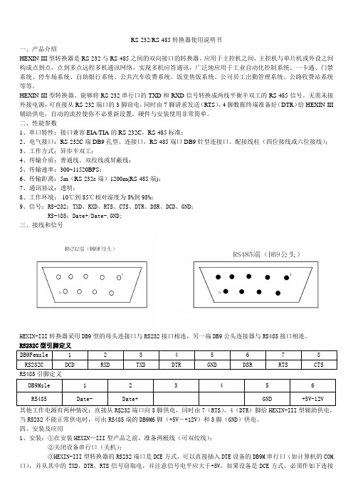
二、性能参数1、串口特性:接口兼容EIA/TIA的RS-232C,RS-485标准;2、电气接口:RS-232C端DB9孔型、连接口,RS-485端口DB9针型连接口、配接线柱(四位接线或六位接线);3、工作方式:异步半双工;4、传输介质:普通线、双绞线或屏蔽线;5、传输速率:300~11520BPS;6、传输距离:5m(RS-232c端)1200m(RS-485端);7、通讯协议:透明;8、工作环境:-10℃到85℃相对湿度为5%到95%;9、信号:RS-232:TXD、RXD、RTS、CTS、DTR、DSR、DCD、GND;RS-485:Date+/Date-,GND;三、接线和信号HEXIN-III转换器采用DB9型的母头连接口与RS232接口相连,另一端DB9公头连接器与RS485接口相连。
RS232C型引脚定义DB9Femsle 1 2 3 4 5 6 7 8RS232C DCD RXD TXD DTR GND DSR RTS CTS RS485引脚定义DB9Msle 1 2 3 4 5 6 RS485 Date- Date+ GND +5V-12V其他工作电源有两种情况:直接从RS232端口向3脚供电,同时由7(RTS)、4(DTR)脚给HEXIN-III型辅助供电,当RS232不能正常供电时,可由RS485端的DB9M6脚(+5V―+12V)和5脚(GND)供电。
Murata 电源转换器 D1U54P-W-1200-12-HC4PC 用户指南说明书

/supportFor full details go to /rohsORDERING GUIDE Part NumberPower Output High Line AC Power Output Low Line AC Main Output Standby Output Airfl ow D1U54P-W-1200-12-HC4PC 1200W 1100W 12Vdc3.3Vdc Back to front D1U54P-W-1200-12-HA4PC 5Vdc D1U54P-W-1200-12-HC3PC 3.3Vdc Front to backD1U54P-W-1200-12-HA3PC5Vdc1 Refer to page 5 for alternate connector pinout assignment (HxxC).2Refer to page 7 for alternate input connector (HxxxKC).3The HCxxC variants are certifi ed for compliance to 80 PLUS ® Platinum effi ciency requirements.INPUT CHARACTERISTICS ParameterConditionsMin.Nom.Max.Units Input Voltage Operating Range 90115/230264Vac Input Frequency 4750/6063Hz Turn-on Input Voltage Ramp up 808589Vac Turn-off Input VoltageRamp down 657378Maximum current at Vin = 100Vac 1100W12Arms Inrush Current Cold start between 0 to 200msec 25ApkPower FactorAt 230Vac, full load 0.99Effi ciency (230Vac) excluding fan load 20% load90%50% load94100% load 91OUTPUT VOLTAGE CHARACTERISTICS NominalOutput VoltageParameter Conditions Min.Typ.Max.Units 12V Nominal Output Voltage 12VdcOutput Set Point Accuracy 50% load; Tamb =25°C -0.5+0.5%Line and Load Regulation-1.0+1.0Ripple Voltage & Noise 420MHz Bandwidth150mV p-p Output Current (230Vac)5100A Output Current (120Vac)590Load Capacitance30,000μF 3.3VSBNominal Output Voltage 3.3Vdc Output Set Point Accuracy 50% load; Tamb = 25°C -0.5+0.5%Line and Load Regulation-1.0+1.0Ripple Voltage & Noise 420MHz Bandwidth75mV p-p Output Current 3A Load Capacitance1000μF 5VSBNominal Output Voltage 5.0Vdc Output Set Point Accuracy 50% load; Tamb = 25°C -0.5+0.5%Line and Load Regulation-1.0+1.0Ripple Voltage & Noise 420MHz Bandwidth75mV p-p Output Current 03A Load Capacitance1000μF4Ripple and noise are measured with 0.1 μF of ceramic capacitance and 10 μF of tantalum capacitance on each of the power supply outputs. A short coaxial cable with 50Ω scope termination is used.FEATURES⏹1200W output power ⏹80 PLUS ® Platinum effi ciency ⏹12V main output⏹3.3V and 5V standby output⏹1U height: 2.15" x 12.65" x 1.57"⏹28 Watts per cubic inch density⏹N+1 redundancy capable,including hot plugging (up to 8 in parallel) ⏹Active current sharing on 12V main output; ORing FET ⏹Overvoltage, overcurrent, overtemperature protection ⏹Internal cooling fan (variable speed) ⏹PMBus™ / I²C interface with status indicators ⏹RoHS compliantPRODUCT OVERVIEWThe D1U54P-W-1200-12-HxxxC series are 80 PLUS ® Platinum effi ciency 1200 watt, power factor corrected front endsupplies with a 12V main output and a 3.3V (3A) or 5V (3A) standby. They have active current sharing and up to 8 supplies may be operated in parallel. The supplies may be hot plugged, they recover from overtemperature faults, and have status LEDs on their front panel in addition to logic and PMBus™ status signals. Their low profi le 1U package and >28W/cubic inch power density make them ideal for delivering reliable, effi cient power to servers, workstations,storage systems and other 12V distributed power systems.CBTest Certi fi cate and Test ReportPM/en/3d/acdc.html /en/3d/acdc.html /en/3d/acdc.html /en/3d/acdc.html /en/3d/acdc.html /en/3d/acdc.html Available now at/en/3d/acdc.htmlContact Murata Sales for availability of variants with this connector confi guration.Murata Power Solutions, Inc. makes no representation that the use of its products in the circuits described herein, or the use of other technical information contained herein, will not infringe upon existing or future patent rights. The descriptions contained herein do not imply the granting of licenses to make, use, or sell equipment constructed in accordance therewith. Specifi cations are subject to change without notice. © 2014 Murata Power Solutions, Inc.Murata Power Solutions, Inc. 11 Cabot Boulevard, Mansfi eld, MA 02048-1151 U.S.A.ISO 9001 and 14001 REGISTEREDThis product is subject to the following operating requirementsand the Life and Safety Critical Application Sales Policy: Refer to: /requirements/。
电子产品EPM Serie 2-3W宽输入范围DC-DC转换器说明说明书
Selection Guide 2:1 2W OutputMODEL NUMBER INPUTVOLTAGE(VDC)OUTPUTVOLTAGE(VDC)OUTPUTCURRENT(mA)INPUT6CURRENT(mA) EFF(%)7ISOLATION8(VDC)PACKAGEFULLLOADNOLOADPM22-01(-3K) 4.5-9 3.3 500 465 50 71 1500(3000) H PM22-02(-3K) 4.5-9 5 400 555 50 72 1500(3000) H PM22-03(-3K) 4.5-9 9 222 519 50 77 1500(3000) H PM22-04(-3K) 4.5-9 12 150 480 50 75 1500(3000) H PM22-05(-3K) 4.5-9 15 120 456 50 79 1500(3000) H PM22-06(-3K) 9-18 3.3 500 205 30 67 1500(3000) H PM22-07(-3K) 9-18 5 400 219 20 76 1500(3000) H PM22-08(-3K) 9-18 9 222 225 20 74 1500(3000) H PM22-09(-3K) 9-18 12 168 209 20 80 1500(3000) H PM22-10(-3K) 9-18 15 133 209 20 80 1500(3000) H PM22-11(-3K) 9-18 24 83 213 20 78 1500(3000) H PM22-12 9-18 +/-5 +/-200 225 20 74 1500 H PM22-13 9-18 +/-12 +/-83 225 20 74 1500 H PM22-14 9-18 +/-15 +/-67 225 20 74 1500 H PM22-15(-3K) 18-36 3.3 500 93 12 74 1500(3000) H PM22-16(-3K) 18-36 5 400 110 12 76 1500(3000) H PM22-17(-3K) 18-36 9 222 111 13 75 1500(3000) H PM22-18(-3K) 18-36 12 168 104 11 80 1500(3000) H PM22-19(-3K) 18-36 15 133 105 11 79 1500(3000) H PM22-20(-3K) 18-36 24 83 107 11 78 1500(3000) H PM22-21 18-36 +/-5 +/-200 112 12 74 1500 H PM22-22 18-36 +/-12 +/-83 112 12 74 1500 H PM22-23 18-36 +/-15 +/-67 112 12 74 1500 H PM22-24(-3K) 36-75 3.3 500 46 8 75 1500(3000) H PM22-25(-3K) 36-75 5 400 56 8 74 1500(3000) H PM22-26(-3K) 36-75 9 222 55 8 75 1500(3000) H PM22-27(-3K) 36-75 12 168 51 8 82 1500(3000) H PM22-28(-3K) 36-75 15 133 51 8 82 1500(3000) H PM22-29(-3K) 36-75 24 83 54 8 77 1500(3000) H PM22-30 36-75 +/-5 +/-200 56 8 74 1500 H PM22-31 36-75 +/-12 +/-83 54 8 77 1500 H PM22-32 36-75 +/-15 +/-67 54 8 77 1500 H Note: Other input to output voltages may be available. Please contact factory.FOR EXAMPLE: PM22-12(H PACKAGE 2W SINGLE OUTPUT 1500VDC ISOLATION)PM22-11(-3K)(H PACKAGE 2W SINGLE OUTPUT 3000VDC ISOLATION)6NOMINAL INPUT VOLTAGE.7 NOMINAL INPUT VOLTAGE, FULL LOAD.Selection Guide 2:1 2W OutputMODEL NUMBERINPUTVOLTAGE(VDC)OUTPUTVOLTAGE(VDC)OUTPUTCURRENT(mA)INPUT9CURRENT(mA) EFF(%)10ISOLATIO N11(VDC)PACKAGEFULLLOADNOLOADPM22-33 4.5-9 3.3 500 465 50 71 1500 J PM22-34 4.5-9 5 400 555 50 72 1500 J PM22-35 4.5-9 9 222 519 50 77 1500 J PM22-36 4.5-9 12 150 500 50 72 1500 J PM22-37 4.5-9 15 120 500 50 72 1500 J PM22-389-18 3.3 500 205 30 67 1500 J PM22-399-18 5 400 219 20 76 1500 J PM22-409-18 9 222 225 20 74 1500 J PM22-419-18 12 168 213 20 78 1500 J PM22-429-18 15 133 213 20 78 1500 J PM22-439-18 24 83 213 20 78 1500 J PM22-4418-36 3.3 500 93 12 74 1500 J PM22-4518-36 5 400 112 12 74 1500 J PM22-4618-36 9 222 111 13 75 1500 J PM22-4718-36 12 168 107 11 78 1500 J PM22-4818-36 15 133 107 11 78 1500 J PM22-4918-36 24 83 107 11 78 1500 J PM22-5036-75 3.3 500 52 8 67 1500 J PM22-5136-75 5 400 56 8 74 1500 J PM22-5236-75 9 222 55 8 75 1500 J PM22-5336-75 12 168 51 8 82 1500 J PM22-5436-75 15 133 51 8 82 1500 J PM22-5536-75 24 83 54 8 77 1500 J Note: Other input to output voltages may be available. Please contact factory.9NOMINAL INPUT VOLTAGE.10 NOMINAL INPUT VOLTAGE, FULL LOAD.Selection Guide 4:1 2W OutputMODEL NUMBERINPUTVOLTAGE(VDC)OUTPUTVOLTAGE(VDC)OUTPUTCURRENT(mA)INPUT12CURRENT(mA) EFF(%)13ISOLATION14(VDC)PACKAGEFULLLOADNOLOADPM24-01(-3K) 9-36 3.3 500 205 30 70 1500(3000) H PM24-02(-3K) 9-36 5 400 222 20 74 1500(3000) H PM24-03(-3K) 9-36 9 222 225 20 74 1500(3000) H PM24-04(-3K) 9-36 12 165 213 20 78 1500(3000) H PM24-05(-3K) 9-36 15 133 213 20 78 1500(3000) H PM24-06(-3K) 9-36 24 83 213 20 78 1500(3000) H PM24-07 9-36 +/-15 +/-67 220 20 76 1500 H PM24-08(-3K) 18-75 3.3 500 98 12 70 1500(3000) H PM24-09(-3K) 18-75 5 400 112 12 74 1500(3000) H PM24-10(-3K) 18-75 9 222 112 13 74 1500(3000) H PM24-11(-3K) 18-75 12 165 107 11 78 1500(3000) H PM24-12(-3K) 18-75 15 133 107 11 78 1500(3000) H PM24-13(-3K) 18-75 24 83 107 11 78 1500(3000) H Note: Other input to output voltages may be available. Please contact factory.12NOMINAL INPUT VOLTAGE.13 NOMINAL INPUT VOLTAGE, FULL LOAD.Selection Guide (4) 2:1 3W OutputMODEL NUMBERINPUTVOLTAGE(VDC)OUTPUTVOLTAGE(VDC)OUTPUTCURRENT(mA)INPUT15CURRENT(mA) EFF(%)16ISOLATION17(VDC)PACKAGEFULLLOADNOLOADPM32-01(-3K) 4.5-9 3.3 700 641 100 72 1500(3000) H PM32-02(-3K) 4.5-9 5 600 800 100 75 1500(3000) H PM32-03(-3K) 4.5-9 9 333 778 100 77 1500(3000) H PM32-04(-3K) 4.5-9 12 250 779 100 77 1500(3000) H PM32-05(-3K) 4.5-9 15 200 779 100 77 1500(3000) H PM32-06 4.5-9 +/-5 +/-300 789 100 76 1500 H PM32-07 4.5-9 +/-12 +/-125 779 100 77 1500 H PM32-08 4.5-9 +/-15 +/-100 779 100 75 1500 H PM32-09(-3K) 9-18 3.3 700 263 45 73 1500(3000) H PM32-10(-3K) 9-18 5 600 336 45 74 1500(3000) H PM32-11(-3K) 9-18 9 333 320 45 78 1500(3000) H PM32-12(-3K) 9-18 12 250 320 45 78 1500(3000) H PM32-13(-3K) 9-18 15 200 310 45 81 1500(3000) H PM32-14 9-18 +/-5 +/-300 324 45 77 1500 H PM32-15 9-18 +/-12 +/-125 320 45 78 1500 H PM32-16 9-18 +/-15 +/-100 320 45 78 1500 H PM32-17(-3K) 18-36 3.3 700 128 20 75 1500(3000) H PM32-18(-3K) 18-36 5 600 162 20 77 1500(3000) H PM32-19(-3K) 18-36 9 333 152 20 82 1500(3000) H PM32-20(-3K) 18-36 12 250 158 20 79 1500(3000) H PM32-21(-3K) 18-36 15 200 154 20 81 1500(3000) H PM32-22 18-36 +/-5 +/-300 162 20 77 1500 H PM32-23 18-36 +/-12 +/-125 158 20 79 1500 H PM32-24 18-36 +/-15 +/-100 158 20 79 1500 H PM32-25(-3K) 36-75 3.3 700 66 12 73 1500(3000) H PM32-26(-3K) 36-75 5 600 81 12 77 1500(3000) H PM32-27(-3K) 36-75 9 333 80 12 78 1500(3000) H PM32-28(-3K) 36-75 12 250 79 12 79 1500(3000) H PM32-29(-3K) 36-75 15 200 76 12 82 1500(3000) H PM32-30(-3K) 36-75 24 125 79 12 79 1500(3000) H PM32-31 36-75 +/-5 +/-300 81 12 77 1500 H PM32-32 36-75 +/-12 +/-125 79 12 79 1500 H PM32-33 36-75 +/-15 +/-100 79 12 79 1500 H15NOMINAL INPUT VOLTAGE.16 NOMINAL INPUT VOLTAGE, FULL LOAD.Input Fuse Selection Guide4.5-9VINPUT VOLTAGE(VDC) 9-18V(9-36V) INPUT VOLTAGE(VDC) 18-36V(18-75V) INPUT VOLTAGE(VDC)36-75V INPUT VOLTAGE(VDC) 2000mA Slow-Blow Type1000mA Slow-Blow Type500mA Slow-Blow Type 200mA Slow-Blow TypeNote: Certain applications may require the installation of external fuse in front of the input.EPM 2-3 Watt Series Application Notes: EXTERNAL CAPACITANCE REQUIREMENTS:No external capacitance is required for operation of the EP 2-3 Watt series.To meet the reflected ripple requirements of the converter, an input impedance of less than 0.5 ohm from DC to 100KHz is required.External output capacitance is not required for operation, however it is recommended that 10uF tantalum and 0.1uF ceramic DC-DCCONVERTER+Vin-Vin+Vout-VoutOUTPUTINPUT。
转换器使用说明书

转换器使用说明书亲爱的用户,感谢您选择本公司的产品和服务。
对技术完美性的追求是我们的目标,我们的理念是产品不求多,只求精。
请您在使用本机前详细阅读此说明书,以便方便您安装使用。
注意:本手册未经本公司的许可,不得任意复制、拷贝、翻译或以其他形式进行发送。
本手册所提及的商标和名称皆属本公司所有。
未经本公司许可而对产品及本说明书进行修改所造成的产品功能不实现、损伤或对其他产品、人造成的影响,本公司将不负任何责任。
对于以合法渠道取得本公司产品的用户,本公司将提供三个月保换、一年保修的服务,但不包括操作不当,人为原因的故障及伤害。
本手册若有任何内容修改或变更,将不另行通知。
XX年X月版本:V4.0一、系统简介XX转换器型设备1~8条E1电路点对点地传输以太网MAC帧数据,设计最高传输速率可达16.384Mbps。
设备不仅提供了线路侧、以太网侧完备的告警指示,而且提供了包括线路的误码率统计,以太网数据流量统计等全面的管理信息,便于构建可统一运营的接入网。
二、技术特性1,实现1-8路E1通道承载100M以太网数据。
2,以太网接口标准的MII接口,只支持100M,全双工工作模式;内置流量统计,可汇报给网管以太网收发的流量统计和错包率等信息;对超长、超短和CRC错包进行过滤;最大支持2036字节的超长包;支持PAUSE流量控制功能;可通过以太网进行管理(可选)3,线路接口1-8路E1通道。
必须成对使用,但可以不对称使用;自动检测可用通道数目,该通道数据也可以通过网管关断;具有AIS、LOS、LOF和误码率告警,其中误码率的具体数据可以通过网管查询;误码关断及误码门限可由网管设置;支持远端环回,支持线路通道误码检测(利用HDLC控制帧);发起远端环回时,禁止向以太网侧发送数据;可检测外部E1环回,禁止向以太网侧发送数据;XX码型4,网管支持XX网管。
可通过以太网进行管理;8bits设备地址输入,最多统一管理256个设备网管信息全面,包括本端和远端的各E1线路状态,以太网端口信息和流量统计。
电源转换器产品说明说明书
TABILITY50 dB-50 dB0 dB 180°-180°0°100HZ1KhZ10KH 100KHZFREQUENCYPhase GainAll specifications are typical @+25°C with nominal input voltage under full output load conditions, unless otherwise noted. Specifications subject to change without notice./powerconversionIndustrial & military grade high density DC to DC converters4-40 UNC-2B THRU 4 PLACES-C Option-B Option-A Option.040 DIA ± .005.50 / 12.7 MIN..30 / 7.6.38 / 9.7marking surfacebase plate.50 / 12.7MIN..15 / 3.81234+ V IN IN RTN TRIM TTL PAR POWER GOOD+ S 056SYNC7891011+ OUT - OUT - STolerances:inches -x.xx x.xxx= ±0.03= ±0.015mm -x.xx.xx = ±0.8= ±0.401111 Knox Street TorranceCA 90502USATel: +1 310 202 8820*********************All specifications are typical @+25°C with nominal input voltage under full output load conditions, unless otherwise noted. Specifications subject to change without notice./powerconversionPerformance characteristics50 dB-50 dB0 dB How to Order:50 T M / 5 / 15 - A Phase GainNB50TT RIPLEOUTPUT3/powerconversionIndustrial & military grade high density DC to DC converters.125 / 32.875 / 1.275 / 32.391.450 / 36.831.100 / 27.94.925 / 23.504-40 UNC-2B THRU 4 PLACES1.875 / 47.632.00 / 50.8.975 / 24.77 -C Option-B Option-A Option-A Option.040 DIA ± .005.50 / 12.7 MIN..30 / 7.6.38 / 9.7marking surfacebase plate.50 / 12.7MIN..15 / 3.81234+ V IN IN RTN TRIM TTL Inches / MillimetersPOWER GOOD+ S.825 / 20.96.675 / 17.15.375 / 9.53.750 / 19.051.125 / 28.586SYNC7891011+ MAIN OUT MAIN RTN- S.125 / 3.181.625 / 41.28.125 / 3.183.00 / 7121314+ AUX OUT AUX COM - AUX OUT .575 / 14.61.400 / 10.161.875 / 47.63Tolerances:inches -x.xx x.xxx= ±0.03= ±0.015mm -x.xx.xx = ±0.8= ±0.40DCTODC C ONVERTERSAll specifications are typical @+25°C with nominal input voltage under full output load conditions, unless otherwise noted. Specifications subject to change without notice./powerconversionPerformance characteristics50S NB100NB150Performance CharacteristicsIX. TTL Turn OnIII. Efficiency vs. Input VoltageII. Efficiency vs. Output PowerVI. Input Transient ResponseV. Load Transient ResponseIV. Output Voltage RippleVII. Input Inrush CurrentVIII. Input Current RippleX. TTL Turn-offXI. Turn-onXII. Turn-off / Hold-up TimeInput Voltage E f f i c i e n c y100%80%60%40%20%0%90%85%80%75%70%65%60%20% 40% 60% 80% 100%90%85%80%75%70%65%60%14 18 22 26 30 34 38Output Load Input Voltage20 m V /d i vTime: 2 μS/div Time: 0.5 mS/divTime: 0.2 mS/div20 V /d i v 0.2 V /d i vTime: 50 μS/div Time: 2 μS/div Time: 0.5 mS/div20 A /d i v 20 V /d i v0.2 A /d i v5 V /d i v 2 V /d i v10 V /d i v 5 V /d i vTime: 100 μS/divTime: 0.5 mS/divTime: 100 μS/div 5 V /d i v 2 V /d i v5 V /d i v 20 V /d i vV = 28 Vdc, V = 15 Vdc, I = 3.3 AV = 28 Vdc, V = 15 Vdc50 - 100% Step LoadOutput CurrentOutput VoltageOutput VoltageInput VoltageV = 15 Vdc, I = 3.3 A14 - 40V TransientV = 28 Vdc, V = 15Vdc, I = 3.3 AInput VoltageInput CurrentV = 28 Vdc, V = 15 Vdc, I = 3.3 AV = 28 Vdc, V = 15 Vdc, I = 3.3 ATTL SignalOutput VoltageV = 28 Vdc, V = 5 Vdc, I = 3.3 AOutput VoltageInput Voltage V = 28 Vdc, V = 15 Vdc, I = 3.3 AInput VoltageOutput VoltageV = 28 Vdc, V = 15 Vdc, I = 3.3 AOutput VoltageTTL Signal 3.3V5V12V24V15V28V 24V 15V 12V 5V 3.3V2V15V 12V10 11 12 13 4028V2V5/powerconversionNBF50 EMI filtersHow to Order:Inches / Millimeters .125 / 3.181.625 / 41.281.375 / 34.93.625 / 15.88.875 / 22.23.125 / 3.184-40 UNC-2B THRU 4 PLACES 1.50 / 38.11.050 / 26.671.375 / 34.93.450 / 11.43.125 / 3.18-C Option-B Option-A Option-A Option.040 DIA ± .005.50 / 12.7 MIN..30 / 7.6.38 / 9.7marking surfacebase plate.50 / 12.7MIN..15 / 3.81234+ IN- IN+ OUT - OUT1.75 / 44.528V in - 50 wattsMIL-STD-461D, CE102With NBF50Without NBF50CASE DRA WING0.01 0.02 0.04 0.06 0.8 0.1 0.2 0.4 0.6 0.8 1 2 4 6 8 10120100806040200-201201008060402000.03 0.04 0.06 0.08 0.1 0.2 0.4 0.6 0.8 1 2 4 6 8 10dBuA dBuV kHzMHzTolerances:inches -mm-x.xx x.xxx x.x x.xx= ±0.03= ±0.015= ±0.8= ±0.40NBF50>> 181111 Knox Street TorranceCA 90502USATel: +1 310 202 8820*********************All specifications are typical @+25°C with nominal input voltage under full output load conditions, unless otherwise noted. Specifications subject to change without notice.6/powerconversionEaton is a registered trademark. All other trademarks are property of their respective owners.Eaton1000 Eaton Boulevard Cleveland, OH 44122 United States © 2017 EatonAll Rights Reserved March, 2017ore-mail:*******************。
APC 电源冗余转换器 说明书

4、 连接 PowerChute 电缆 • 当你准备安装 PowerChuteplus 时,请将 PowerChuteplus 通讯电缆安装在冗余开
关的服务器端口和服务器的串口之间。
个合格的电工能够将内部四针蓝色的阴极连接器连接到紧急停电系统。这样一来,紧
急停电系统就可以运行了。只要系统启动,UPS 系统都会停止供电。
注意 紧急停电系统接口是一个安全低压电路,只可以与其他安全低压电路连接。紧 急停电系统是一个控制电路,不需要有源电压。所用闭环电路应通过与市电隔 离的开关或者继电器实现。使用其他非闭环电路会损害冗余开关。
前部面板用户操作 用户操作设置面板位于冗余开关的前部,便于操作。
ΟΟΟ功能选择 LED 指示灯 这三个绿色的 LEDS 显示用户选择的状态参数,使用左边的键可以选择以上所列 5 种 用户设置。 Ο 功能状态 LED 指示灯 绿色的功能状态 LED 显示用户所选的功能状态。使用左边的键可以进行选择。
AC 电源 LED 指示灯
电源,连接安装完毕后再接通电源。 • 在处理任何金属连接器之前,应该先断开电源。 • 尽量使用一只手连接或者断开信号电缆,以免碰触两极,遭到电击。 • 将设备连接到三相 AC 电源(火,零和地)。插座应该有适宜的电路保护装置(保
险丝和电路断路器)。和其他类型的插座相连可能会引起电击危险。 注意:断电安全 • 断电步骤:按住 UPS 的电源开关,保持一秒钟以上,关掉 UPS 电源。然后从 AC
如果 PowerChute plus多次显示:self test failed: invalids test, UPS-A 失去了输出电压 功能,请通过 PowerChute plus做自检,如果自检失败,则按照随电源附带的 SmartUPS 快速参考指示排除故障,如需协助请遵照服务部分指示。
莫仕20(25)W系列AC DC电源转换器说明书

20(25)W,AC-DC converterFEATURES●Universal input range:85~264V AC,100~370VDC ●Regulated output,low ripple and noise ●Efficiency up to 87%●Over-current,shortcircuitand over-voltageprotection●Plastic case,meets UL94V-0●IEC60950,UL60950,EN60950Approval●PCB mounting,Chassis mounting,DIN-Rail mountingCBRoHSLH 20-25series -----a compact size power converter offered by Mornsun.It features universal input voltage,taking both DC and AC input voltage,low power consumption,high efficiency,high reliability,safer isolation.It offers good EMC performance,which meetIEC/EN61000-4,CISPR22/EN55022,UL60950and EN60950standards,and it’s widely used in industrial,office and civil applications.For harsh EMC environment,the application circuit in the datasheet is strongly recommended.Selection GuideCertificationPart No.*Output PowerNominal Output Voltage andCurrent Efficiency (230V AC,%/Typ.)Max.CapacitiveLoad(µF)(Vo1/Io1)(Vo2/Io2)Vo1Vo2UL/CE/CBLH20-10B0313.53W3.3V/4100mA --7448000--LH20-10B0517.5W5V/3500mA --7812240--LH20-10B0920W9V/2100mA --807200--LH20-10B1212V/1600mA --825400--LH20-10B1515V/1300mA --832720--LH20-10B2424V/850mA --851840----LH20-10A05+5V/2000mA -5V/2000mA 7580008000LH20-10A12+12V/830mA -12V/830mA 82960960LH20-10A15+15V/650mA -15V/650mA 83880880LH20-10C0505-055V/2500mA ±5V/500mA 74112004480LH20-10C0512-045V/2000mA ±12V/400mA 75160001600LH20-10C0515-035V/2000mA ±15V/300mA 7613520370LH20-10C0524-025V/2000mA ±24V/200mA 7711200370LH20-10D0512-065V/2500mA 12V/600mA 75324003250LH20-10D0515-055V/2500mA 15V/500mA 76280001980LH20-10D0524-035V/2500mA 24V/300mA7728000720UL/CE/CBLH25-10B0313.53W 3.3V/4100mA --7448000--LH25-10B0520.5W5V/4100mA --7912240--LH25-10B0925W 9V/2500mA --815600--LH25-10B1212V/2100mA --835400--LH25-10B1515V/1600mA --842400--LH25-10B2424V/1100mA --851440--LH25-10B4848V/500mA--87500--Note:*About LH20-10AXX,use both positive and negative output as sampling feedback;and all others use Vo1as sampling feedback.Input SpecificationsItemOperating Conditions Min.Typ.Max.Unit Input Voltage Range AC input 85--264V AC DC input100--370VDC Input frequency 47--63HzInput current 115V AC ----0.6A 230V AC ----0.34Inrush current 115V AC --16--230V AC--30--Leakage current0.3mA RMS typ./230V AC/50Hz Recommended External InputFuse(Special package series include fuse) 3.15A/250V,slow fusing Hot PlugUnavailableOutput SpecificationsItemOperating Conditions Min.Typ.Max.UnitOutput Voltage Accuracy Main circuit --±2--%Line RegulationFull loadMain circuit --±0.5--Auxiliary circuit --±1.5--Load Regulation10%-100%loadSingle output--±1--Dual output(balanced load)--±2--Isolated triple output (balanced load)Main circuit --±3--Auxiliary circuit --±5--Isolated and separated twin output (balanced load)Main circuit --±3--Auxiliary circuit--±5--Ripple &Noise*20MHz bandwidth (peak-peak value)--50100mV Temperature Coefficient Main circuit--±0.02--%/°C Short Circuit Protection Continuous,self-recovery Over-current Protection≥110%Io self-recoveryOver-voltage ProtectionMain circuit3.3/5VDC Output ≤7.5VDC 9VDC Output≤13VDC 12/15VDC Output ≤20VDC 24VDC Output ≤30VDC 48VDC Output≤60VDCMin.LoadSingle output models0----%Dual output models (balanced load)10----Isolated and separated twin output (balanced load)10----Isolated triple output (balanced load)10----Hold-up Time115V AC input --15--ms 230V AC input--80--Note:*Ripple and noise are measured by “parallel cable”method,please see AC-DC Converter Application Notes for specific operation.General SpecificationsItemOperating Conditions Min.Typ.Max.Unit Isolation VoltageInput-outputTest time:1min 3000----V ACOperating Temperature LH20-10A/C/D series -25--+70°C LH20(25)-10B series -40--+70Storage Temperature LH20-10A/C/D series -25--+85LH20(25)-10B series-40--+85Storage Humidity----95%RHWelding Temperature Wave-soldering 260±5℃;time:5~10s Manual-welding360±10℃;time:3~5sSwitching Frequency--65--kHzPower Derating-25℃~-10℃(LH20-10A/C/D Series)2.0-----40℃~-10℃(LH20(25)-10B Series) 2.0----+50℃~+70℃(LH25-10B Series)3.0----+55℃~+70℃(LH20-10A/B/C/D Series)4.0----Safety Standard IEC60950/EN60950/UL60950Safety Certification IEC60950/EN60950/UL60950Safety Class CLASS IMTBFMIL-HDBK-217F@25°C >300,000h Physical SpecificationsCasing MaterialBlack flame-retardant and heat-resistant plastic (UL94-V0)DimensionHorizontal packageg70.00x48.00x23.50mm A2chassis mounting 96.10x54.00x32.00mm A3chassis mounting 99.00x54.00x32.00mm A4Din-Rail mountin96.10x54.00x36.60mm WeightHorizontal package/A2chassis mounting/A3chassis mounting/A4Din-Rail mounting120g/170g /170g /210g (Typ.)Cooling methodFree convectionEMC SpecificationsEMICE CISPR22/EN55022,CLASS B RE CISPR22/EN55022,CLASS B EMSESD IEC/EN61000-4-2±6KV/±8KV Perf.Criteria B RSIEC/EN61000-4-310V/m perf.Criteria A EFT IEC/EN61000-4-4±2KVperf.Criteria B IEC/EN61000-4-4±4KV (See Fig.5for recommended circuit)perf.Criteria B Surge IEC/EN61000-4-5±1KV/±2KVperf.Criteria B IEC/EN61000-4-5±2KV/4KV (See Fig.5for recommended circuit)perf.Criteria B EMSCSIEC/EN61000-4-610Vr.m.s perf.Criteria A PFMIEC/EN61000-4-810A/m perf.Criteria A Immunities of voltage dip,drop and short interruptionIEC/EN61000-4-110%-70%perf.Criteria BProduct Characteristic Curve-401007020-1055704050Te mperature Der ating C ur veL 25-10B s eriesH LH20-10A/B/C/D se rie s Ambient Temperature()℃O u t p u t P o w e r P e r c e n t a g e (%)L 20-10A/C/D s eries H LH20(25)-10B s eries -25Input voltage:85~264VAC 100~370VDC100240852642040100608075Input VoltageAmbient temperature:25℃Input Voltage Derating CurveO u t p u t P o w e r P e r c e n t a g e (%)VAC 120340100370VDCNote:①When input 85~100VAC/240~264VAC/100~120VDC/340~370VDC,it need to be voltage derated on basis of temperature derating;②This product is suitable for use in natural air cooling environments,if in a closed environment,please contact our company’s FAE.Design Reference1.Typical application circuitAC(L)+Vo-VoAC(L)AC(N)AC(N )C 1C 2TV SRLF USE AC DC MO VNTCFig.1:LH20(25)-10B series (Single Output)Typical application circuitF USE+VoAC(L)AC(N)-VoAC(N )C omC 4C 2C 1C 3RLTV S1TV S2RLNTCAC(L)AC DC MO VFig.2:LH20-10A series (Dual Output)typical application circuit+-C 1C 4C 3C 2-Vo1Vo2TV S1TV S2RLRLFUSE AC(L)AC(N)AC(N )NTC+AC(L)ACDCM OVFig.3:LH20-10D series (Isolate Twin Output)typical application circuit+C 1C 4C 3C 2-Vo1C om TV S1TV S2RLRLFUSE AC(L)AC(N)AC(N )AC(L)ACDCMO V+Vo2C 6C 5TV S3RL-Vo2NTCFig.4:LH20-10C series (Triple Output)typical application circuitModel C2(µF)C4(µF)C6(µF)TVS1TVS2TVS3LH20-10B03330SMBJ7.0A LH20-10B05330SMBJ7.0A LH20-10B09220SMBJ12A LH20-10B12220SMBJ20A LH20-10B15220SMBJ20A LH20-10B24220SMBJ30A LH20-10A05470470SMBJ7.0A SMBJ7.0A LH20-10A12120120SMBJ20A SMBJ20A LH20-10A156868SMBJ20A SMBJ20A LH20-10C0505-0533*******SMBJ7.0A SMBJ7.0A SMBJ7.0A LH20-10C0512-0433*******SMBJ7.0A SMBJ20A SMBJ20A LH20-10C0515-03330120120SMBJ7.0A SMBJ20A SMBJ20A LH20-10C0524-023304747SMBJ7.0A SMBJ30A SMBJ30ALH20-10D0512-********SMBJ7.0A SMBJ20A LH20-10D0515-********SMBJ7.0A SMBJ20A LH20-10D0524-03330120SMBJ7.0A SMBJ30ALH25-10B03330SMBJ7.0A LH25-10B05330SMBJ7.0A LH25-10B09330SMBJ12A LH25-10B12330SMBJ20A LH25-10B15330SMBJ20A LH25-10B24120SMBJ30A LH25-10B4868SMBJ64ANote:Note:Output filtering capacitors C2,C4,C6are electrolytic capacitors,it is recommended to use high frequency and low impedance electrolytic capacitor.For capacitance and current of capacitor please refer to manufacture’s datasheet.Capacitor withstand voltage derating should be 80%or above.C1,C3,C5are ceramic capacitors,which is used to filter high-frequency S is a recommended component to protect post-circuits if converter fails.External input NTC is recommended to use 5D-9.External input MOV model is recommended to use S14K300.2.EMC solution-recommended circuitACDCAC(N)AC(L)LCMMOV1CXCY1CY2FUSEAC(N)AC(L)+Vo-Vo+LDMC1C2TVS1RLCan use MORNSUN s FC-LX1D' Fig 5:EMC Recommended circuit with higher requirementsElement Recommended valueMOV1S14K300CY1,CY21000pF/400V AC CX 0.1μF/275V ACLCM 10mH,recommended to use MORNSUN’s FL2D-Z5-103LDM 4.7μH/2A FC-LX1D 2KV/4KV EMC filterFUSE3.15A/250V slow fusing,necessary3.Application of Trim and calculation of Trim resistance0V R 2R 1R 3V ref R TTrim+Vot0V R 2R 1R 3V ref R TTrim+VotTrim upTrim downApplied circuits of Trim (Part in broken line is the interior of models ):Calculation formula of Trim resistance:up: R 1R =T aR 2R -a 2-R 3down: a=VrefVot-Vref R 2R =T aR 1R -a1-R 3R T is Trim resistancea is a self-defined parameter,withno real meaning.Vout R1(K Ω)R2(K Ω)R3(K Ω)Vref(V)Vot(V)3.3V 3.3 1.981 1.24Output voltage after regulation,variation ≤±10%5V 3.3 3.31 2.59V 7.5 2.871 2.512V 3.8311 2.515V 7.5 1.51 2.524V 8.6611 2.548V683.7312.54.For more information about Mornsun EMC Filter products,please visit todownload the Selection Guide of EMC FilterDimensions and Recommended Layout LHXXA2DimensionsLHXXA3Dimensions LHXXA4DimensionsNotes:1.Packing information please refer to Product Packing Information which can be downloaded from .Packingbag number of Horizontal package:58220006,the Packing bag number of A2/A3/A4package:58220010;2.If the product is not operated within the required load range,the product performance cannot be guaranteed to comply with allparameters in the datasheet;3.Unless otherwise specified,parameters in this datasheet were measured under the conditions of Ta=25℃,humidity<75%with nominalinput voltage and rated output load;4.All index testing methods in this datasheet are based on our Company’s corporate standards;5.The performance parameters of the product models listed in this manual are as above,but some parameters of non-standard modelproducts may exceed the requirements mentioned above.Please contact our technicians directly for specific information;6.We can provide product customization service;7.Specifications are subject to change without prior notice.MORNSUN Guangzhou Science&Technology Co.,Ltd.Address:No.5,Kehui St.1,Kehui Development Center,Science Ave.,Guangzhou Science City,Luogang District,Guangzhou,P.R.China Tel:86-20-38601850-8801Fax:86-20-38601272E-mail:***************。
AIMS 纯正正弦波直流电源转换器操作手册说明书

Operation ManualRack typeCongratulationsonpurchasingyour high quality A IMS Power pure sine wave inverterIt is very important thatyou read and understand this instruction manual completely priorto use.Contained a re i mportant c onnection t ips, s afety i ssues, a nd w arranty i nformationContentsPg. 03 Specifications (1000W-DC12V, 24V, 48V 120Vac)Pg. 04 Specifications (2000W-DC12V, 24V, 48V 120Vac)Pg. 05 Specifications (3000W-DC12V, 24V, 48V 120Vac)Pg. 06 RS232 communication port and communication program operation methodPg. 07 RS232 communication port and communication program operation methodPg. 08 Transfer switch system / LED displayPg. 09 Features and benefitsPg. 10 Use of DC battery / Use of 120Vac powerPg. 11 Inverter input cable (wiring) Terminal fixing method by sequencePg. 12 Sketch of DC/AC connections, Each section and name (1000W)Pg. 13 Sketch of DC/AC connections, Each section and name (2000W/3000W)Pg. 14 Explanation for each sectionPg. 15 Explanation for each sectionPg. 16 Operating procedurePg. 17 TroubleshootingPg. 18 General problemsPg. 19 Warnings and warranty informationPg. 20 Warranty card02Specifications (1000W-DC12V, 24V, 48V 120Vac)►Product Use• Telecom equipment • Audio-video e quipment • Router /Hub • Computers03Specifications (1000W-DC12V , 24V , 48V 120Vac)Specifications (2000W-DC12V, 24V, 48V 120Vac)►Product Use•Telecom equipment • Audio-video e quipment • Router /Hub •Computers 04Specifications (3000W-DC12V, 24V, 48V 120Vac)►Product Use• Telecom equipment • A udio-video e quipment • Router /Hub • Computers05Specifications (3000W-DC12V , 24V , 48V 120Vac)Connect Connect Disconnect● RS232 communication port controls with non-synchronous serial transmission (ASCII cord) method.● RS232 communication program is real time operation, and status can be monitored through serial function of PC screen by program connected with and provided by computer (PC) application port.AIMS Power RS232 program execution①Run p rogram e xecution f ile i n f igure A IMS Power 232.exe② When you start the program, it will run as shown in the figure. Check once more if inverter cable is well connected before running program.Once connection is made, user’s PC port connected with inverter should be set. When clicking on PORT COM3 ▼ port in program screen, it will show choices of 1 to 10. Find and select inverter and PC port from the choices.③ When p ort selection i s made, click o n to start communication between i nverter a nd P C.If port is not properly selected or cable connection is made incorrectly,or inverter power is off, messagefail Port open will appear along with confirmation window. In this case, press OK to close window, select a correct p ort o r d ouble c heck t he c able c onnection s tatus.④ If connection is established normally, button turns into button indicates connection between inverter and PC is established normally.If connection is made completely, inverter DC input voltage, AC output voltage, frequency, and output current can be verified using buttons at the lower part of the program screen.06RS232 communication port and communication program operation methodSer ealport andPOR T COM3 ▼ B audr ate 2400 ▼ Conne ct ExitData Bits8▼Stop bits▼P arit yNONE ▼D C i n p u t 00 v AC o u t p u t 00 v F r e q u e n c y 00 Hz Am p00vConne ctRS232 communication port and communication program operation methodDC input 00 v AC output 00 v Frequency 00HzAmp00v⑤ DC input Click on DC input button, DC input voltage details are shown.AC output Click o n A C o utput b utton, A C o utput v oltage d etails a re s hown. Frequency Click o n F requency b utton, f requency d etails a re s hown. Amp Click on Amp button, output current details are shown.⑥ For disconnection between inverter and PC after usage, click onSerealDisconnectbutton, this button turns into button, and indicatesPORT COM3 ▼Baudrate 2400 ▼ DisconnectExitData Bits 8 ▼Stop bits▼ParityNONE ▼disconnection of devices.For r econnection, repeat ③ details o nce m ore.To completely close program, use X button on program window or click on Exit button t o e nd t he p rogram.● When using RS232 communication programs other than ones provided by our company, data in each mode can be verified using following command through PC connection.Input voltage indication command: BAT? Output v oltage i ndication c ommand: V OL? Frequency indication command: FRQ? Output current indication command: AMP?When entering commands in the command window, even question marks should be typed accurately, and make sure to use upper case as it distinguishes upper and lower c ases.07communication port and communication program operation methodD C i n p u t 00 v AC o u t p u t 00 v F r e q u e n c y 00 Hz Am p00v수정중입니다Transfer switch systemThis product was developed using digital circuit design based on a patented technology DSP (digital signal processor), and is a very reliable, h igh p erformance, l ight w eight i nverter.● 120Vac is either supplied by city power(by pass mode) or inverter(DC or backup mode). A p rogram will control this automatically or it may be manually controlled(by city power circuit breaker) ● By pass modeStandard operation is for the city power to provide ac outUpon A C city power mode f ailure, output is converted to inverter mode through DC conversion.If AC city power is restored, unit will revert back to bypass mode (city power) automatically by the transfer switch program. ● DC or backup m ode.In DC mode (city power circuit breaker OFF) the inverter will supply ac out power as long as the dc supply provides enough voltage to inverter.LED display●UP, DOWN switchUsing UP/DOWN s witches o n panel, information in each mode o f inverter can b e v erified through the LED display. If p ower i s t urned o n, o utput v oltage i s d isplayed f irst. W hen u sing U P b utton, o utput v oltage -> o utput c urrent -> frequency -> input voltage shows in display in order. When using DOWN button, output voltage -> input voltage -> frequency -> output current shows in display in order.● When using UP b utton① Output voltage display② Output current display③ Frequency display④ Input voltage display08(DC12V/24V/48V)• By using a D.S.P. (digital signal processor) driver this inverter can safely generate its pure sine wave at a high quality 120Vac output.• The product responds to the high and low battery voltage changes and adapts its output perfectly to ensure a stable 120Vac.• The innovative technology of this pure sine wave inverter will support t he u sage o f s ensitive l oads.• FCC part 15 subpart 16 B class BReference• All DC to AC operations are automatically controlled by the D.S.P. program.• The improved efficiency of this inverter ensures nominal output voltage even at low input DC voltage.• Since output voltage is within 3% of the variation input voltage (12V, 24V and 48V) stable power will always be produced for your AC loads.• This product has excellent driving power with a surge output that’s 2 times higher than the output capacity. This allows you to exceed the inverters listed output for a short period of time (500 milliseconds) to power some devices with quick startup surges. • With various protection circuits built in, this product will automatically shut down at low voltage or in the event of a sudden change of input/output power. The inverter also shows excellent performance and reliability control during rapid environmental changes such as ambient temperature.• This inverter is designed with the most advanced circuitry available in order to suppress most RF noise produced by inverting DC voltage to 120Vac.This product is a Digital Signal Processed inverter that utilizes DC 12V, 24V or 48V to generate the 120Vac power. When the 120Vac pure sine wave inverter is properly used within the capacity listed on various electronic devices. Please follow all connection instructions to avoid damage or injury to the inverter and yourself. Failure to follow the warning messages and to connect the inverter properly will cause malfunction o f t he i nverter a nd m ay v oid t he w arranty.Featur es and bene fi tsFeatur es and bene fi ts09Prior t o u sing t his p roduct p lease r ead t his o peration m anual t horoughly. I nappropriate u se m ay c ausedamage t o t he p roduct! Please c heck t hrough t his m anual o n y our n ew i nverter b efore o perating.e of battery (DC power)•12V Battery : When using 500 watts of output (120Vac) with a 100A b attery, you can use this product for 2 hours(8.3A used under 100W) in optimal conditions.•24V Battery : When using 500 watts of output (120Vac) with a 100A b attery, you can use this product for 4 hours(4.2A used under 100W) in optimal conditions.•48V Battery : When using 500 watts of output (120Vac) with a 100A b attery, you can use this product for 8 hours(2.1A used under 100W) in optimal conditions.II . Use of AC power outlet (120Vac)The product h as an o utput f unction o f 120Vac.Although the output A C cord is different based on thickness, 150 Ft. length can be used in general conditions.III.Alarm display function (red L ED)•Output short circuit•Output overload•Over temperature protection•Battery low voltage (alarm/LED)•Battery high voltage (alarm/LED)IV.Fan operationBased on the 120Vac load o f this p roduct the f an a utomatically operates when the temperature increases.Thermal fan engages at 104°F ~113°F101 212 3 3 4 54 5Round Fixed Terminal Order① F lat washer② ⊕ Red terminal ⊖ Black terminal of the battery cable ③ S pring w asher ④ H exagon n ut⑤ 8Ø Terminal cover knob(to prevent short)use to select the input wiring specifications that meet the criteria, d epending on the installation location and Hexagon nuts with the t erminal and p erfectly fixed.be used to add a secondary battery in accordance with the output of the equipment used.11Black ⊖input cable (wiring) Terminal fixing method by sequence■ Inverter input cable (wiring) Terminal fixing method by sequence•Input/Output connection diagramParalleconnectionSeries connectionSeriesconnectionSeriesconnectionPC connection TV/Monitor Router/HUB City powerconnectionSeriesconnection ⑤City power③Overload protection⑦LED displayup,down selection switch⑧Automatic fan•Each section and name②Inverter on switch④Inverter⑬RS232port①D C Input⑨Ou t pu t power mai n swi tc h⑥120V ac output(circuit breaker switch)⑩cit y p ower so ck et(cit y p ower input)⑪City powerbreaker switchThis product contains battery connections and sparks can easily occur.To prevent fire or other accidents,do not install this inverter in a small orpartitioned area with flammable materials.Wet or moist environments are fatalWarning to this inverter.Special care should be taken.keep inverter out of direct sunlight.12⑬ RS232 port⑫ A C T erminal b lock (120Vac)⑨ Output power main switch (circuit b reaker s witch)① DC input power⑥ 120Vac outlet⑭ E arth⑩ city power socket (city power input)⑪ City power breaker switch 13Parallel connection Series connectionPC connection TV / Monitor Router / HUBCity power input⑤City power③Overload protection⑦LED displayup, down selection switch ⑧ Automatic fan②Inverter on switch ④Inverter■ Sketch of DC/AC connections, Each section and name (2000W/3000W)Important1)Input Terminal (12V, 24V or 48V)Prior to any connections make sure you match the battery voltage to the inverter input voltage. You will probably notice an arc whenconnecting a discharged or new power inverter to your batteries. Make sure to connect battery ( ) to Black and battery ( ) to Red.Tighten terminals. I n c ase of extreme v ibration, g o b ack and v erify terminals are tight.2)Inverter on switch/LEDThis is the main unit power switch. When this is turned off, the inverter is off. When turned on, the inverter is on.This LED always lights up when the power switch is on or this inverter is in operation.3)Overload protection LED'sThis LED should not illuminate unless an error occurs. The error may be temporary, such as an overload. It may also indicate apermanent failure. If it is lit, try disconnecting all loads, and reset inverter.4)InverterThis lamp is on whenever unit is connected to battery and not in city power mode.Even when inverter on switch is off and no city power is present.5) C ity p owerThis lamp is always turned on when using city power.6)120Vac outletIt is 120Vac power outlet.147) LED display / UP, DOWN selection switchUsing UP/DOWN switches on panel, information in each mode of inverter can be verified through the LED display.If power is turned on, output voltage is displayed first. W hen using UP b utton, output voltage -> output current -> frequency -> input voltage shows i n d isplay i n o rder. W hen u sing D OWN b utton, o utput v oltage -> i nput v oltage -> f requency -> o utput c urrent s hows i n d isplay i n o rder.● When using UP button8) Automatic fan operation① Output voltage display ② Output current display ③ Frequency display ④ Input voltage display(DC12V/24V/48V)These f ans a re t hermally c ontrolled a nd w ill t urn o n a utomatically w hen n eeded. 9) Output power main switch / circuit breaker switch Main circuit b reaker switch of o utput power.10) City power socket / City power input (120Vac)When this input power is available, city power may pass through to output.11) City power breaker switchReset position : default power out will be city, inverter power out if city power unavailable OFF p osition : I nverter only mode. 12) AC Terminal Block(120Vac)This Terminal Block is a convenient way of direct connecting equipment to achieve the full output power of the inverter. Be very careful as these may be "hot" and if touched may cause severe injury and electrical shock. Warning : I t is r ecommended to have a p rofessional e lectrician wire to these t erminals.If t hey are t ouched, they may cause severe shock and if wired incorrectly may cause p ermanent damage to the i nverter and equipment, voiding warranty and in extreme cases may cause f ire.13) RS232 communication port (Please r efer t o p age6~7 d isplay o peration m ethod f or d etails.)14) Earth15Importantfor each sectionA.Verify the battery operating voltage and protection switch is on (inverter off).B.Tum protection switch "off "(circuit breaker) once the battery connection has been verified.C.The l ength o f t he c able may vary slightly, b ut s hould p referably b e l ess t han 10 F t. T he s horter t he l ength o f t he c able t he b etter t hebatteries will perform.If a longer distance is needed, a larger gauge cable is required.minimum cable size recommendations : 12Vdc / 4Awg, 24Vdc / 6Awg, 48Vdc / 8AwgD.Connect the Red cable lug to the p ositive on the battery and Black lug to the negative of the battery.Arrange the b attery cables to the safest angles. T urn inverter on and confirm inverter is o perating properly.E.Turn protection switch "off " If the buzzer is sounding, turn the connected A C devices off and toggle the power switch off then on.The buzzer should stop.F. Now you should connect and turn the A C devices on. Most equipment using motors, have a higher startup requirement.This may cause the inverter to buzz and go into overload or pop the circuit breakers. This should not damage the inverter;however you should not continue to try and power up the equipment. Repeated overloads will cause damage to the inverter CallAlMS P ower T ech s upport a nd v erify s tartup r equirements.G.The frequency of the inverter is fine-tuned at 60Hz from the manufacture.H.The i nverter m ay o perate i n o verload f or a s hort p eriod o f t ime. I f y ou c ontinue t he u se i n o verload, t he i nverter may o verheat a ndshut down. You will then be required to turn the inverter off and on again.16TroubleshootingFor r ed L ED a nd P rotection s witchTips for improving inverter service l ifeBefore using the inverter with heavy motors or appliances, it is wise to verify the startup requirements. This is most often much higherthan t he l isted r unning r equirements a t 3t o 5t imes t he c ontinuous c urrent r ating.To k eep t he l ife e xpectancy o f t he i nverter a t i ts m aximum, p lease e nsure p lenty o f v entilation. K eep d ust a nd f oreign d ebris o ut o f i nverter.17Audio system noise : Noise may be generated from speakers or amplifier when using the inverter to power low-grade stereosystems and large portable radios. This is due to the interference between the electricity and currentrunning through each d evice. Y ou are h earing the RF generated b y the inverter.TV interference : The operation of this inverter may cause interference in receiving specific TV channels; in this caseperform t he f ollowing p rocedure’s t o t ry t o r esolve t he p roblems.Audio, TV and wireless devices shall be installed in an area as far as possible away from the inverter. Try installing a line filteron a ffected d evice.Cautions during use•For normal operation, devices with excessive loads applied momentarily such as refrigerators , air conditioners, electric motors,hand tools Etc. Should be within 60% of the maximum output capacity of this inverter. Check the capacity of this inverter as wellas the capacity of the intended devices to be used.•When the rated continuous capacity of the motor is equal to or greater than the rated capacity of the inverter, operation of theintended device may not be available due to the inverters lack of surge ability.•Devices using heaters will increase the temperature of the inverter drastically. When using devices like this make sure to provideproper ventilation for the inverter. Improper ventilation will cause inverter shutdown and malfunction resulting in irreversibledamage.•Audio and video devices shall be used within the maximum power rating of the inverter. If the rating capacity is exceeded therewill be a momentary cut-off. For safe operation use 75%-80% of the listed capacity.18Warnings•Never allow moisture into or around inverter. This will void your warranty•Allow plenty of ventilation around inverter. It needs air to keep cool, or it may get extremely hot and shut down•Avoid placing the inverter in direct sun light•Always keep inverters away from flammable objectsAIMS Power™ Warranty Instructions:This product is designed using the most modern digital technology and under very strict quality control and testing guidelines. If however you feel this product is not performing as it should, please callTechsupport (775)359-6703 ex227************************We will do our b est t o r esolve y our concerns. If the product n eeds repair or replacement, m ake sure to keep you receipt/ invoice, as that will need to be sent back along with the inverter prepaid to A IMS. You have a full 1 year from date of purchase warranty19。
电源转换器产品说明书

Ratings• UL ா 1008 Listed•CSA ா C22.2 No. 178 CertifiedIndustrial design highlights•Double-throw, mechanically interlocked transfer mechanism • Front accessible •Top, bottom and side cable entry•Internal cable gutter space•Seismic Zone 4 qualified (CBC and IBC)• OSHPD certification •Field-selectable, multi-tap transformer permits wide range of system voltages •Manual operation under load with permanently affixed handle• Internal deadfront cover • Padlock provision •Self-protecting switching contacts•Mechanical lug terminationStandard and optional controller featuresDescriptionAutomatic ControllerATC-100ATC-300+ATC-900Basic transfer control, plant exerciser, timedelays, self diagnostics and system settings Standard Standard Standard Source mimic diagram with LED indication Standard Standard Standard Engine test and start contact Standard Standard Standard Dual source control power input StandardStandard Standard Liquid crystal display (LCD)Standard Standard Programmable set points and plant exerciser Standard Standard Password protectionStandard Standard Time-stamped history and event log Standard Standard Time delay bypassStandard Standard Go to source 2 control input Standard Standard Pre-transfer and general alarm control outputsStandard Standard Lockout and monitor modesStandard Standard Source status output relay contacts Standard Standard Modbus ா RTU communication Standard Standard Manual retransfer control input Optional Standard Source 2 inhibit / load shed inputOptionalStandard USB port—profile and data management Standard Preferred source selection Standard Dual generator capabilityStandard User configurable inputs/outputsStandard Advanced diagnostics and troubleshooting with pre-/post-event data capture Standard Integrated load meteringOptional Load management with selective load shed Optional DC voltage control power inputOptional Three-source ATS—master/slave control Optional Modbus TCP/IP communication AOptionalOptionalA Modbus TCP/IP option requires use of Modbus RTU port.Unmatched performance, reliability and versatilityEaton’s molded-case switch/circuit breaker (MCS/MCCB) type automatic transfer switch (ATS) is designed toprovide unmatched performance, reliability and versatility for critical standby power applications requiring open transition with time delay. Configurable features include integral overcurrent protection and service entrance rated equipment.Product confi gurations• 30–1000 A, 100% rated • Two-, three- and four-pole • Single- and three-phase • 120–600 Vac, 50/60 Hz •NEMA ா 1, 3R, 12, 4X enclosure types• Open frame•Open transition with time delay•ATC-100, ATC-300+, ATC-900 controller • Service entrance rated •Integrated meteringEaton is a registered trademark.All other trademarks are property of their respective owners.Eaton1000 Eaton Boulevard Cleveland, OH 44122United States © 2014 EatonAll Rights Reserved Printed in USAPublication No. PA140005EN / Z15340July 2014Catalog numbering systemotee:N The catalog numbering system for molded-case switch/breaker ATS offers a wide variety of standard configurations to meet your application needs. Please be advised that some catalog number combinations are not available. Please contact your local Eaton sales representative with any quotation-related questions.Service entrance equipmentEaton’s MCS/MCCB type transfer switch can easily be configured to be suitable for use as service equipment in the standard enclosure size.Service equipment rated transfer switches may be installed at the point of service entrance without the need for separate upstream disconnect devices and additional power connections.All service equipment is UL 1008 Listed and includes integral overcurrent protection, keyed service disconnect switch and fused disconnect of control power.UL 1008 short-circuit withstand/close-on ratings (kA)Switch Ampere UL 1008 Short-Circuit “Any Breaker” RatingUL 1008 Rating When Used With Upstream Fuse Maximum Fuse Fuse A Four-pole configuration is 35 kA.Optional accessories• Overcurrent protection with thermal-magnetic trip • Integrated distribution circuit breaker panel• Automatic controller protective cover with padlock provision • Surge protection device (UL 1449 3rd Edition)•Remote annunciator controller—monitor and control single or multiple automatic transfer switches •Ethernet gateway with Web server (Modbus TCP/IP , SNMP , BACnet)•Space heater with thermostatEnclosure dimensions and approximate shipping weightMCS/MCCB Frame Transfer Switch Ampere Enclosure Dimensions (Inches) A Approx.Shipping Weight lbs (kg) ATC-300+ATC-900A NEMA 1 and 3R type.B Standard three-pole configuration.C Applies to single-phase, 120/240 Vac or 120/208 Vac, three-wire and three-phase, 208/120 Vac,four-wire standard configurations without multi-tap transformer.D All other three-phase, standard configurations that include multi-tap transformer.Standard cable terminal connectionsSwitchAmpere MCS/MCCB Standard Cu/Al Terminal Lugs (kcmil)Normal and Emergency A Applies to standard two- and three-pole configurations with solid neutral.CUSTOM ORDER ENGINEERINGIn many cases, standard product can be custom- order engineered to meet your application needs. For additional information, please contact your local Eaton sales representative.。
VPI 型接口转换器使用说明书

根据GB/T 3836.1的指示2020322316003409 测量转换器使用说明书VPI版本: 04.2023 I 应用范围VPI型接口转换器用于提供可在潜在爆炸性环境中使用的本安型传感器。
此外,该转换器还用于在非本质安全区和本质安全区之间转换电信号。
它主要是作为罐体内容测量的一部分。
该转换器被设计成一个内置模块,有八个本安通道。
VPI-Supply类型的电源用于供应接口转换器。
II 标准安全屏障是根据以下标准设计的GB/T 3836.1-2021 设备--一般要求GB/T 3836.4-2021 本质安全 "i "的设备保护III 关于安全的说明III.a 使用接口转换器有八个本安型传感器电路,可以接入0区,并可用于所有气体组。
VPI-Supply型电源可用于转换器的辅助电源。
在特殊条件下,可以使用任何其他电源。
为此,转换器必须连接到电位均衡器。
非本安型控制电路(RS-485接口)与一个四极插头相连。
与上级数据处理系统的连接是由这个插头进行的。
III.b 装配和拆卸接口转换器和电源是用开放式塑料外壳制造的,用于DIN导轨安装。
不允许打开外壳!III.c 安装接线只能在断电的情况下进行。
必须遵守特殊规定,如GB/T 3836.15或当地的安装规定。
接口转换器必须安装在危险区域之外的、防护等级至少为IP20的外壳内。
确保非本质安全的线路连接与本质安全的传感器终端有至少50毫米的距离。
当从传感器到接口转换器布线时(最好是蓝色电缆),不得超过第V节规定的允许的电感和容量。
终端指定:III.d 调整对于操作来说,没有必要进行与防爆有关的调整。
III.e 投入服务在投入使用前,必须检查所有设备的连接和安装是否正确。
必须检查电力供应,包括连接的设备。
III.f 维护、大修和修理这些设备通常是免维护的。
在出现缺陷的情况下,必须将相应的组件退回给制造商FAFNIR或其代表之一。
本质安全传感器电路和通信端口之间符合GB/T 3836.4第6.3.13条的绝缘强度要求。
SC2987降压型PWM转换器说明书
一、概述SC2987是一款降压型PWM转换器,典型输出驱动电流为3.8A无需外加晶体管。
设计允许它可在8V~48V的宽输入电压下工作。
通过将COMP/EN脚逻辑电平拉低来控制外部关断功能,使其进入待机模式。
外部补偿使反馈控制具有良好的线性调整率和负载调整率,具有灵活的外围设计。
SC2987的特点之一是具有可编程的CV/CC模式控制功能。
CV(恒压)模式提供了一个稳定的输出电压,CC(恒流)模式提供了一个限流功能。
在电流检测放大器输入期间,CC电流值通过外部电阻设定。
SC2987适用于需要用到电流限制功能的DC/DC开关电源上。
该器件采用ESOP-8L封装,且工作时只需要很少的外围器件。
二、特性●电压输入范围:8V~48V●线电压Vout(Vref=1.2V)精度为±1%●CC/CV模式控制(恒流和恒压)●限流精度为±5%●输出短路保护●过压保护(超出输出电压的118%)●过温保护●内置软启动,启动时间12ms●固定频率120kHz●UVLO保护●占空比范围(0~90%)●单独的引脚进行外部补偿和关断控制●集成N-MOSFET●ESOP-8L封装三、应用●车充●便携式充电设备●高亮度照明设备●具有限流功能的多功能DC/DC变换器四、极限参数描述范围单位输入电压V VCC-0.3~50 VBST相对LX 0.3~7 VLX相对GND的直流电压-1~V VCC+1 VBST相对GND的直流电压-0.3~7 VFB,COMP相对GND的直流电压0.3~7 V ISEN-,ISEN+相对GND的直流电压0.3~9 V储存温度范围-65~150 ℃结点温度-20~150 ℃导热温度(焊接10s) 260 ℃人体模式ESD 2 KV机器模式ESD 200 V封装热阻ESOP-8L 60 ℃注意:如果器件工作条件超出上述各项极限值,可能对器件造成永久性损坏。
上述参数仅仅是工作条件的极限值,不建议器件工作在推荐条件以外的情况。
DC-DC 电源转换器说明书

DC TO AC POWER INVERTERPWRNV1250W INSTRUCTION MANUALSAVE THIS MANUALYou will need the manual for the safety warnings and precautions, assembly instructions, operating and maintenance procedures, parts list and diagram. Keep your invoice with this manual. Write the invoice number on the inside of the front cover. Keep the manual and invoice in a safe and dry place for future reference.Basic Operation•Make sure that you choose the right operating voltage for both input and output of the inverter.•When unpacking, make sure that the inverter is in good condition. If any parts are missing or broken, please call AIMS Power, Inc. at the number found on the warranty card.•Place the power inverter on a flat surface. Make sure it has adequate ventilation and is not in direct sunlight. Fasten the inverter securely to the surface, using screws or some othermeans. If holes are to be drilled, follow safe, proper installation techniques.Before you connect the battery cables, make sure the power switch is in the off position. Connect Red (+) battery cable to Red (+) inverter terminal. Connect Black (-) battery cable to Black (-) inverter terminal. Connect Red (+) battery cable to Red (+) battery terminal. Connect Black (-) battery cable to Black (-) battery terminal. Alligator clamp cables may be used but only to connect to the battery.Do not use clamps on inverter terminals. Alligator clamps are not a permanent solution. You may see a spark during connection.•Connect the ground cable to an earth ground, such as a metal water pipe or to the vehicle ground when used in a vehicle if the inverter includes a ground port.•Turn the power switch to the on position, which is located on the front of the inverter. The green LED light will confirm that AC power is present.•Before plugging the equipment into the inverter, make sure the equipment AND the inverter are off. Turn inverter on first, then turn on the equipment.•The power inverter can be used either while the engine is running or off.Warnings•Unplug the inverter when it is not in use.•If the AC inverter makes a beeping sound, turn off the equipment, unplug the inverter and restart the vehicle’s engine. The beeping sound is simply the low-battery warning, which indicates that the voltage of your battery is getting low. If you do not re-start your engine and continue operating the inverter, the inverter will automatically shut off, leavingyour vehicle's battery at about 10. 5 VDC. This will allow you to start your engine and resumeoperation of the inverter. It also reduces the fear of being stranded with a dead battery(dependent on health of battery).•This device should only be serviced by a qualified technician. This item does not have any serviceable parts.•Prevent body contact with grounded surfaces such as pipes, radiators, ranges, and refrigerator enclosures during installation.•Do not operate the inverter if under the influence of alcohol or drugs. Read warning labels on prescriptions to determine if your judgement or reflexes are impaired while taking drugs. Ifthere is any doubt, do not operate the inverter.•People with pacemakers should consult their physician(s) before using this product.Electromagnetic fields in close proximity to a heart pacemaker could cause interference to or failure of the pacemaker.•Keep children away. Children must never be allowed in the work area. Do not let them handle machines, tools, or extension cords.•Store idle equipment. When not in use, inverter must be stored in a dry location to prevent rust. Always lock up tools and the inverter and keep out of reach of children.•Size the inverter properly. Size the inverter for the surge rating of your equipment. The inverter’s continuous rating should be MORE than the surge rating of your equipment.Example: Power tool runs at 1500 watts but surges at 2500 watts. You should use an inverter >3000 watts.•Keep the inverter well-ventilated. Do not place any objects on top of or next to the inverter or allow anything to cover the cooling fans; doing so can cause the inverter to overheat,causing a potential fire hazard and/or damage to the inverter. Leave adequate ventilationspace underneath the inverter as well; thick carpets or rugs can obstruct air flow, causing the inverter to overheat.•Avoid unintentional starting. Be sure the switch is in the OFF position when not in use and before plugging in any appliance.Note: Performance of this unit may vary depending on the available battery power or appliance wattage.Warning: The warnings, cautions, and instructions discussed in this instruction manual cannot cover all possible conditions and situations that may occur. It must be understood by the operator that common sense and caution are factors which cannot be built into this product, but must be supplied by operator. Guard against electric shock. Do not open the metal case; risk of electric shock.Battery Use•To avoid over-discharging your vehicle battery, we recommend running your engine for 10-20 minutes to recharge the vehicle's battery if battery voltage drops <11V.•To properly size your battery, use the following formula: Volts * Amps = Watts or Watts/Volts = Amps. Example: 1000 watt inverter / 12 volts DC = 83.3 DC amps. In this example, you willneed 83.3 amps to power a 1000 watt load for 1 hour. If you need to power 1000 watts for 2hours you will need 83.3 * 2 = 166.66 DC amps available. A 100 amp hour battery will giveyou 100 amps / 166.66 = .6 hours so you will need two batteries if using 100 amp battery.This is if you fully deplete your batteries. We do NOT recommend fully depleting yourbatteries. This is just an example. Your power requirements may be different.•If you choose to use a female 12 Volt DC adapter for your inverter or to the inverter make sure wire size is correct.•IF YOU CONNECT THE WIRES TO THE INCORRECT TERMINALS, YOU WILL REVERSE THE POLARITY AND DAMAGE THE INVERTER.•REVERSED POLAR ITY WILL INSTANTLY VOID THE WARRANTY OF YOUR INVERTER, SO BE CAREFUL TO CONNECT YOUR INPUT WIRES PROPEPLY.•If you choose to operate a battery charger to replenish your battery’s voltage, be sure to check with charger manufacture before damaging the charger.•CONNECTING THE INVERTER’S DC INPUT TO A BATTERY CHARGER WILL VOID THE WARRANTY, AND MAY DAMAGE THE INVERTER.•Make sure that the battery voltage does not exceed 15 volts DC.•CONNECTING THE INVERTER TO A DC POWER SOURCE GREATER THAN 15 VDC WILL VOID THE WARRANTY, AND MAY DAMAGE THE INVERTER.CablesWe recommend that you refrain from using battery cables longer than 12 feet between the DC power source and the DC input of the inverter. Longer battery cables on the DC input will create a voltage drop which results in a reduction of efficiency and output. If you require more than 12 feet, use a bigger cable. We recommend using an extension cord between the AC output and AC appliance. You may use up to 100ft, high quality extension cord. A longer cord may result in reduced output. See Specifications chart for recommended battery cable size.Digital Bar DisplayThe digital bar display displays battery DC voltage and DC current. The current should always be in the green zone. The inverter will operate for several minutes when thecurrent is in the yellow zone. Operation in the red zone of the display will result in protective inverter shutdown. NOTE: The bar display will only monitor DC current and voltage not AC. If you need to measure AC output you will need to use a TRUE RMS MULTI METER.Remote On/Off SwitchSome models include a remote port. An AIMS remote on/off switch may be connected to the remote port. The optional remote on/off switch is a convenient option to turn the inverter on/off if the inverter is installed in a hard to reach area. Make sure the inverter is turned off before installing the remote switch. Simply plug the switch into the remote jack. There are several ways to mount the remote switch. Remote switch comes with 4 pre-drilled holes for mounting. Remote part # REMOTEHF.Measuring the AC VoltageThe output waveform of the inverter is a MODIFIED SINE WAVE. If you choose to measure the AC output voltage, you must use a TRUE RMS MULTI METER. Using any other type of voltage measuring device will result in an AC voltage reading of 10 to 30 volts lower than actual voltage. When using a true RMS multi meter, you will get an accurate reading.SAFETY PRECAUTIONS•Do not open the case of the inverter. The high voltage inside the unit is the same type of power as your electrical outlets at home.•Do not let the cord of the inverter, or any appliance cord get wet. If you are operating the inverter in a moving vehicle, we recommend that you secure the inverter to prevent it fromshifting around while the vehicle is moving.•Do not operate this inverter in or around water. Water can damage the inverter, and water damage is not covered under warranty. Also, do not operate the inverter with wet hands. The AC voltage of the unit makes it an electrical shock hazard if operated with wet hands.•Allow at least one inch of clearance around the Inverter for air flow. Ensure the ventilation openings on the rear and bottom of the unit are not obstructed.•Do not connect the inverter directly to another AC power source. Damage may result, and such damage will void the inverter warranty.•Know the wattage requirements of your appliance. Use only those appliances which are limited by the capacity of this unit.•Use common sense. This device produces power just like your wall outlets at home and should be treated seriously. Keep it away from children.•Reversed polarity of AC power outlet LINE /NEUTRAL will void the warranty.•If there is anything wrong with the inverter, disconnect all of the power and contact technical support.If the Inverter does not appear to be functioning properly, check the following possible causes:•Poor contact: Clean contact parts thoroughly.•If the low battery alarm sounds, this means the input voltage is too low and battery needs to be recharged.•If you are getting a low output voltage, try reducing the load to minimize watts. You may have overloaded the inverter. Reduce your load. Also, keep input voltage above 10.5 volts tomaintain a constant flow of power.•If you are not getting any power output, turn the power switch Off and On again, until the green power light comes on. Your devices may draw too much power to operate them. Theinverter may be in thermal shutdown. Let it cool down and make sure there is adequateventilation around the unit.•If the green light turns red one of the following has happened:A.input voltage is too lowB.input voltage is too highC.short circuitD.inverter is close to overload•Battery voltage is too low: Start the engine to recharge the battery. Replace or recharge battery if needed.•Shuts down on overload: Reduce the wattage of your load.•Thermal shutdown: Under heavy loads for extended period, the inverter will shut down to prevent damage from excess heat. Simply reduce your load and allow theInverter to cool down.•Low-battery shutdown: Recharge your battery and resume operation.Very little maintenance is required to keep your inverter operating properly. You should disconnect input power first and then clean the exterior of the unit periodically with a dry cloth to prevent accumulation of dust and dirt. At the same time, tighten the screws on the DC input terminals.PLEASE READ THE FOLLOWING CAREFULLYNeither the manufacturer nor distributor makes any representation or warranty of any kind to the buyer that he or she is qualified to make any repairs to the product or that he or she is qualified to replace any parts of the product. In fact, the manufacturer and/or distributor expressly states that all repairs and parts replacements should be undertaken by certified and licensed technicians and not by the buyer. The buyer assumes all risk and liability arising out of his or her repairs to the original product or replacement parts thereto, or arising out of his or her installation of replacement parts thereto.WARRANTYAIMS Corp., Inc. dba AIMS Power Warranty Instructions:This product is designed using the most modern digital technology and under very strict quality control and testing guidelines. If, however, you feel this product is not performing as it should, please contact us:**************************(775)359-6703We will do our best to resolve your concerns. If the product needs repair or replacement, make sure to keep your receipt/invoice, as that will need to be sent back along with the package and RMA# prepaid to AIMS. You have a full 1 year warranty from date of purchase.This warranty is valid worldwide with the exception that freight and duty charges incurred outside the contiguous 48 United States will be prepaid by customer.Except as provided above, AIMS makes no warranty of any kind, express or implied, including without limitation the implied warranties of merchantability and fitness for a particular purpose. In no event shall AIMS be liable for indirect, special or consequential damages. This warranty only applies to AIMS Power branded products. All other name brand products are warranted by and according to their respective manufacturer. Please do not attempt to return non-AIMS Power branded products to AIMS Power.For additional products such as:-Modified sine wave inverters-Pure sine wave inverters-Low Frequency Inverters-Solar Charge Controllers-Micro Grid Tied Inverters-Inverter Chargers and Automatic transfer switches-Converters DC-DC-Custom cut cables-Batteries-Solar Panels & RacksPlease visit our web site: Tofindoutwheretobuyanyofourproducts,youmayalsoe-mail:************************ (775)359-6703.。
降压型DC-DC转换器 XL7056 说明书

2.1A 100KHz 100V 降压型DC-DC转换器XL7056特点⏹最高输入电压100V⏹最大占空比85%⏹最小压差2.0V⏹输出电压从1.25V至20V可调⏹5V输出时最大2.1A输出电流⏹15V输出时最大1.2A输出电流⏹固定100KHz开关频率⏹最大输出功率小于20W⏹内置高压功率MOSFET⏹效率高达93%⏹出色的线性与负载调整率⏹内置限流功能⏹内置输出短路保护功能⏹TO263-7L封装应用⏹电动车控制器供电⏹通信描述XL7056是一款高效、高压降压型DC-DC转换器,固定100KHz开关频率,可提供最高2.1A输出电流能力,低纹波,出色的线性调整率与负载调整率。
XL7056内置固定频率振荡器与频率补偿电路,简化了电路设计。
PWM控制环路可以调节占空比从0~85%之间线性变化。
图1. XL7056封装2.1A 100KHz 100V 降压型DC-DC 转换器 XL7056引脚配置CSP CSN FB GNDSW 12345TO263-7LMetal Tab SWVC VIN 67图2. XL7056引脚配置表1.引脚说明引脚号 引脚名 描述 1 GND 接地引脚。
2 FB 反馈引脚,通过外部电阻分压网络,检测输出电压进行调整。
参考电压为1.25V 。
3 CSN 电流检测负端引脚。
4 SW 功率开关输出引脚。
5 CSP 电流检测正端引脚。
6 VC 内部电压调节器旁路电容引脚,需要在VIN 与VC 引脚之间连接1个1uF 电容。
7VIN电源输入引脚,需要在VIN 与GND 之间并联电容以消除噪声。
2.1A 100KHz 100V 降压型DC-DC 转换器 XL7056方框图EABias current & Voltage ReferenceVINGND75mV 1.25VEA COMPOscillator100KHz/25KHzSWRS Latch and DriverFBStart Up UVLOCSNSwitchVCocsCSP图3. XL7056方框图典型应用XL7056L1 100uH/3ACIN 100uF 100VC2105R210K 1%R13.3K 1%D1FSV10150SW FBGNDVINVIN7421CFF 10nF COUT 220uF 16VR30.035Ω 1%C1104VOUT 5V/0~2.1AOUTPUT 5V/0~2.1A VOUT=1.25*(1+R2/R1)CSP 53CSN CC 105VC6R3用于限制最大输出电流,当VOUT ≤5V 时,R3选择0.035欧姆;当VOUT>5V 时,R3选择0.055欧姆。
转换器使用说明书
LD-4102FE FE1-V.35协议转换器User’s Manual用户手册版本号: 1.0修订日期:2006.04.16北京联达科讯科技有限公司BEIJING LIANDA TECHNOLOGY CO.,LTD.亲爱的用户,感谢您选择本公司的产品和服务。
请您在使用本机前详细阅读此说明书,以方便您安装使用。
注意:本手册未经本公司的许可,不得任意复制、拷贝、翻译或以其他形式进行发送。
本手册所提及的商标和名称皆属本公司所有。
未经本公司许可而对产品及本说明书进行修改所造成的产品功能不实现、损伤或对其他产品、人造成的影响,本公司将不负任何责任。
对于以合法渠道取得本公司产品的用户,本公司将提供1个月保换、3年保修的服务,但不包括操作不当,人为原因的故障及伤害。
本手册若有任何内容修改或变更,将不另行通知。
版本:2004年9月V3.02005年5月V3.12009年4月V3.2目录一、产品概述 (4)二、产品特性 (4)1,一般特性 (4)2,技术特性 (4)三、功能描述 (5)1,前面板 (5)2,后面板 (8)四、典型应用 (9)五、安装、调试、故障排除及网管 (10)1,准备工作 (10)2,接地 (10)3,安装 (10)4,调试 (10)5,故障排除 (10)6,网管 (11)六、装箱清单 (12)一、产品概述HM-C104FE1/V.35转换器可以用全部或部分E1时隙传输V.35接口数据,带宽64Kbps-2048Kbps。
可广泛应用于计算机网络互连、DDN数据网接入、移动电话网的传输优化,和基于E1的PCM网络的各种传输接入。
注:设备标识和本说明书中提到的转换器、Converter,是同一含义。
二、产品特性1,一般特性·体积:220×165×35mm·重量:900g·电源:220V±20%,-36~-72V·功耗:小于3W·环境温度:0℃-50℃2,技术特性·可实现V.35接口数据在E1线路中透明传输和分时隙传输,带宽范围64Kbps-2048Kbps·分时隙使用时可以任意设置时隙个数和时隙位置·自适应DTE设备发送的数据相位,方便开通·具备多种环回设置功能,方便检测和开通·具备网络管理功能,可监视设备的工作情况和设置设备的工作状态·同时提供非平衡75Ω和平衡120ΩE1接口·具备E1电路的检测功能·E1接口规范完全符合ITU-T G.703、G.704HDB3码型,完备的线路告警指示输出码速率:2048Kbps±50ppm75Ω物理接口采用BNC标准同轴连接器,120Ω物理接口采用RJ45连接器·V.35接口规范接口方式:DCE接口类型:DB25速率:64Kbps-2048Kbps三、功能描述1,前面板下图是HM-C104FE1/V.35转换器的前面板。
ST Series纯正波形电源转换器用户手册说明书

Pure Sine Wave Power Inverter User’s ManualContents1. Important Safety Instructions (2)1-1 General safety precautions (2)1-2 Precautions when working with Batteries (2)2. Functional Characteristics (3)2-1 General Information (3)2-2 Application (3)2-3 Features (3)2-4 Electrical Performance (5)2-5 Mechanical drawings (9)3. Installation (11)3-1 Where to install (11)3-2 Hard-wire Installation (12)3-3 DC Wiring Connections (15)4. Introduction (19)4-1 Inverter Operation (19)4-2 Front Panel Operation (19)4-3 Protection Features (23)4-4 Rear Panel Operation (24)5 Information (24)5-1 Troubleshooting (24)5-2 Maintenance (25)5-3 Warranty (25)6. Appendices (26)6-1 FCC (Class A) Declaration of Conformity (26)6-2 e-mark (e13) Declaration of Conformity (28)6-3 CE (Class A) Declaration of Conformity (34)6-4 CE (LVD EN60950) Declaration of Conformity (36)a Copyright :This manual is the copyright of COTEK Electronic lnd. Co., Ltd. And may not be reproduced or copiedwithoutthe express permission of the owner.1. Important Safety InstructionsBefore using the Inverter, read and save the safety1-1. General Safety Precautions1-1-1. Do not expose the Inverter to rain, snow, spray, bilge or dust.To reduce risk of hazard, do not cover or obstruct the ventilationopenings. Do not install the Inverter in a zero-clearancecompartment. Overheating may result.1-1-2. To avoid a risk of fire and electronic shock. Make sure that existing wiring is in good electrical condition; and that wire size is notundersized.Do not operate the Inverter with damaged or substandard wiring.1-1-3. This equipment contains components which can produce arcs or sparks. To prevent fire or explosion do not install in compartmentscontaining batteries or flammable materials or in locations whichrequire ignition protected equipment. This includes any spacecontaining gasoline-powered machinery, fuel tanks, or joints, fittings,or other connection between components of the fuel system.1-2. Precautions When Working with Batteries1-2-1. If battery acid contacts skin or clothing, wash immediately with soap and water. If acid enters eye, immediately flood eye with runningcold water for at least 20 minutes and get medical attentionimmediately.1-2-2. Never smoke or allow a spark or flame in vicinity of battery or engine.1-2-3. Do not drop a metal tool on the battery. The resulting spark or short-circuit on the battery of other electrical part may cause anexplosion.1-2-4. Remove personal metal items such as rings, bracelets, necklaces, and watches when working with a lead-acid battery.A lead-acid battery produces a short-circuit current high enough toweld a ring or the like to metal, causing a severe burn.Wire length / gauge Terminal Wire colorST1000&ST1500ST2000&ST2500Line (L) BlackACOUTPUT Neutral (N) WhiteLine (L) BrownACINPUT Neutral (N) BlueGroundGreen /Yellow orBare copperWithin 16 feet / AWG#14~1626~32 feet / AWG#12~14Within 16 feet / AWG#10 ~1226~32 feet / AWG#8 ~103-2-3. Please double check and review all connections to ensurethe wires are in correct terminals and the connections are tight.3-2-4. Before connecting AC output and AC input terminals of the ST series, you can either use front compartment cover or a side hole to coil out.Both AC input and AC output are coiled out from the front compartmentcover when in production. If you want to change the position, youshould open the top cover first, and then switch the wire of the frontcompartment cover and the plastic cover of the side of top cover.2-3-4. Speed up transfer time and synchronized operation with the AC source at all times that allows the transfer to be interruption-free for sensitiveequipments.2-3-5. Built in advance microprocessor to make friendly interface with user. 2-3-6. Low power “ Power Saving Mode “ to conserve energy2-3-7. Capable of driving highly reactive & capacitive loads at start moment. 2-3-8. Hardwire AC connection model option.2-3-9. Loading controlled cooling fan.2-3-10. Smart remote controller.2-3-11. 3 LED indicators with tri-color display all operation status.2-3-12. High efficiency 88 ~ 93%.2-3-13. Protection:Input over voltage and Input low voltage protection.Low battery alarmOver temperature protection.Over load protectionShort Circuit protectionReverse polarity protection.AC circuit breaker (6Amp to 30Amp)Specification Model No.Item ST1000-112 ST1000-124 ST1000-148 ST1000-212 ST1000-224 ST1000-248 Continuous Output Power 1000WMaximum Output Power (3Min.) 1150WSurge Rating 2000WInput Voltage 12V 24V 48V 12V 24V 48VOutput Voltage 100 / 110 / 120V ± 3% 220 / 230 / 240V ± 3%Frequency(Switch Selectable)50 / 60Hz +/- 0.05%Output Waveform Pure Sine Wave (THD < 3%)Efficiency (full load) 88% 91% 92% 90% 93% 94% No Load Current Draw 1.43A 0.75A 0.38A 1.25A 0.65A 0.35A Stand-By Current Draw 0.25A 0.15A 0.09A 0.25A 0.15A 0.09AInput Voltage Regulation 10.5-15VDC21.0-30VDC42.0-60VDC10.5-15VDC21.0-30VDC42.0-60VDCInput Level IndicatorLoad Level IndicatorRed / Orange / Green LED Failure Indicator Red LEDProtection Overload, Short Circuit, Reverse Polarity (Fuse),Over Temperature Over/Under Input Voltage, AC Input Circuit BreakerCircuit Breaker 12 Amp 6 Amp Remote Control Unit CR6 / CR7 / CR8 Optional Synchronous AC transfer YESTransfer switch 16 Ampinverter AC To AC input source 8 ~ 10 msec Transfer TimeAC input source To inverter AC 12 ~ 14 msec Safety Meet UL458 Meet EN60950-1EMC FCC Class A EN55022: 1997EN55024: 1997EN61000-3-2: 1998EN61000-3-3: 1995e-Mark022967Operating Temperature Range 0 – 40¢JStorage Temperature Range -30¢J to 70¢JCooling Loading controlled cooling fanDimensions 373(L)*236(W)*115(H) mm / 14.7(L)*9.29(W)*4.53(H) InchWeight 6.2 kgs. / 13.6 Lbs.Specification Model No.Item ST1500-112 ST1500-124 ST1500-148 ST1500-212 ST1500-224 ST1500-248 Continuous Output Power 1500WMaximum Output Power (3Min.) 1725WSurge Rating 3000WInput Voltage 12V 24V 48V 12V 24V 48VOutput Voltage 100 / 110 / 120V ± 3% 220 / 230 / 240V ± 3%Frequency(Switch Selectable)50 / 60Hz +/- 0.05%Output Waveform Pure Sine Wave (THD < 3%)Efficiency (full load) 88% 91% 92% 90% 93% 94% No Load Current Draw 1.45A 0.75A 0.40A 1.40A 0.70A 0.40A Stand-By Current Draw 0.28A 0.15A 0.09A 0.28A 0.15A 0.09AInput Voltage Regulation 10.5-15VDC21.0-30VDC42.0-60VDC10.5-15VDC21.0-30VDC42.0-60VDCInput Level IndicatorLoad Level IndicatorRed / Orange / Green LED Failure Indicator Red LEDProtection Overload, Short Circuit, Reverse Polarity (Fuse),Over Temperature Over/Under Input Voltage, AC Input Circuit BreakerCircuit Breaker 16 Amp 10 Amp Remote Control Unit CR6 / CR7 / CR8 Optional Synchronous AC transfer YESTransfer switch 25 Amp 16 Ampinverter AC To AC input source 8 ~ 10 msec Transfer TimeAC input source To inverter AC 12 ~ 14 msec Safety Meet UL458 Meet EN60950-1EMC FCC Class A EN55022: 1997EN55024: 1997EN61000-3-2: 1998EN61000-3-3: 1995Meete-MarkOperating Temperature Range 0 - 40¢JStorage Temperature Range -30¢J to 70¢JCooling Loading controlled cooling fanDimensions 403(L)*236(W)*115(H) mm / 15.9(L)*9.29(W)*4.53(H) InchWeight 7.0 kgs. / 15.4 Lbs.Specification Model No.Item ST2000-112 ST2000-124 ST2000-148 ST2000-212 ST2000-224 ST2000-248 Continuous Output Power 2000WMaximum Output Power (3Min.) 2300WSurge Rating 4000WInput Voltage 12V 24V 48V 12V 24V 48VOutput Voltage 100 / 110 / 120V ± 3% 220 / 230 / 240V ± 3%Frequency(Switch Selectable)50 / 60Hz +/- 0.05%Output Waveform Pure Sine Wave (THD < 3%)Efficiency (full load) 88% 91% 92% 90% 93% 94% No Load Current Draw 2.6A 1.50A 0.70A 2.3A 1.1A 0.65A Stand-By Current Draw 0.60A 0.30A 0.2A 0.60A 0.3A 0.15AInput Voltage Regulation 10.5-15VDC21.0-30VDC42.0-60VDC10.5-15VDC21.0-30VDC42.0-60VDCInput Level IndicatorLoad Level IndicatorRed / Orange / Green LED Failure Indicator Red LEDProtection Overload, Short Circuit, Reverse Polarity (Fuse),Over Temperature Over/Under Input Voltage, AC Input Circuit BreakerCircuit Breaker 25 Amp 12 Amp Remote Control Unit CR6 / CR7 / CR8 Optional Synchronous AC transfer YESTransfer switch 25 Amp 16 Ampinverter AC To AC input source 8 ~ 10 msec Transfer TimeAC input source To inverter AC 12 ~ 14 msec Safety Certification Meet UL458 Meet EN60950-1EMC FCC Class A EN55022: 1997EN55024: 1997EN61000-3-2: 1998EN61000-3-3: 1995Meete-MarkOperating Temperature Range 0 - 40¢JStorage Temperature Range -30¢J to 70¢JCooling Loading controlled cooling fanDimensions 433(L)*332(W)*115(H) mm / 17(L)*13(W)*4.53(H) InchWeight 11.2 kgs. / 24.6 Lbs.Specification Model No.Item ST2500-112 ST2500-124 ST2500-148 ST2500-212 ST2500-224 ST2500-248 Continuous Output Power 2500WMaximum Output Power (3Min.) 2875WSurge Rating 5000WInput Voltage 12V 24V 48V 12V 24V 48VOutput Voltage 100 / 110 / 120V ± 3% 220 / 230 / 240V ± 3%Frequency(Switch Selectable)50 / 60Hz +/- 0.05%Output Waveform Pure Sine Wave (THD < 3%)Efficiency (full load) 88% 91% 92% 90% 93% 94% No Load Current Draw 2.35A 1.3A 0.7A 2.4A 1.5A 0.65A Stand-By Current Draw 0.5A 0.35A 0.19A 0.6A 0.35A 0.19AInput Voltage Regulation 10.5-15VDC21.0-30VDC42.0-60VDC10.5-15VDC21.0-30VDC42.0-60VDCInput Level IndicatorLoad Level IndicatorRed / Orange / Green LED Failure Indicator Red LEDProtection Overload, Short Circuit, Reverse Polarity (Fuse),Over Temperature Over/Under Input Voltage, AC Input Circuit BreakerCircuit Breaker 30 Amp 16 Amp Remote Control Unit CR6 / CR7 / CR8 Optional Synchronous AC transfer YESTransfer switch 25 Ampinverter AC To AC input source 8 ~ 10 msec Transfer TimeAC input source To inverter AC 12 ~ 14 msec Safety Certification Meet UL458 Meet EN60950-1EMC FCC Class A EN55022: 1997EN55024: 1997EN61000-3-2: 1998EN61000-3-3: 1995Meete-MarkOperating Temperature Range 0 - 40¢JStorage Temperature Range -30¢J to 70¢JCooling Loading controlled cooling fanDimensions 463(L)*332(W)*115(H) mm / 18.2(L)*13(W)*4.53(H) InchWeight 12 kgs. / 26.4 Lbs.2-5. Mechanical drawings2-5. Mechanical drawings3. Installation3-1.Where to installThe power inverter should be installed in a location that meets the following requirements:3-1-1. Dry – Do not allow water to drip or splash on the inverter.3-1-2. Cool – Ambient air temperature should be between 0¢J and 40¢J, the cooler the better.3-1-3. Safety – Do not install batteries in compartment or other areaswhere flammable fumes existence such as fuel storage areas orengine compartments.3-1-4. Ventilated – Allow at least one inch of clearance around theInverter for air flow. Ensure the ventilation shafts on the rearand bottom of the unit are not obstructed.3-1-5. Dust-free – Do not install the Inverter in a dusty environmentswhere dust, wood particles or other filings/shavings arepresent. The dust can be pulled into the unit when the cooling fan isoperation.3-1-6. Close to batteries – Avoid excessive cable lengths but do not install the inverter in the same compartment as batteries.Use the recommended wire lengths and sizes (see section 4-3).Do not mount the inverter at the place where it is exposed to thegases produced by the battery.These gases are very corrosive and prolonged exposure willdamage the inverter.3-2 Hard-wire InstallationAC wiring connections:3-2-1. The AC wiring compartment is located on the front panel of the ST series. Remove the AC wiring compartment cover to gainaccess to the AC terminal.WARNING!Before you connect AC wiring to the terminals of compartmentcover, ensure to check the label in the compartment forcorrect connections. Wrong connection will damage theinverter.CAUTION !It is advised that all the electrical installation should conform to the localelectrical codes and should be carried out by a certified electrician.When the unit is feeding the internally inverted voltage (Power Status LED is green, power from the AC input source is not available), the current carrying conductors connected to the “L” and “N” terminals of the AC output will beisolated from the metal chassis of the inverter. Hence, during this condition,when the metal chassis of the inverter is connected to the earth ground, the“N” terminal of the AC output will not be grounded (bonded) to the earthground. Under this condition, the “N” terminal of the AC output will not be aNeutral in the true sense. Do not touch this terminal as it will be at anelevated voltage (almost half the value the AC output voltage) with respect to the metal chassis / earth ground and may produce an electrical shock whentouched!When the unit is transferring power from the AC input source (Power Source LED is orange), the grounding condition of the “N” terminal of the AC outputwill be the same as the condition of the “N” terminal of the AC input source. If the AC input source is the power supplied from the utility, the “N” terminalwould be a Neutral in the true sense, will normally be bonded to the earthground and will read almost 0 V with respect to the earth ground. In this case, touching this terminal will not be a shock hazard3-2-2. Connect AC output and AC input wiring to the ST series terminals. Please take the following information as your reference.Wire length / gauge Terminal Wire colorST1000&ST1500ST2000&ST2500Line (L) BlackACOUTPUT Neutral (N) WhiteLine (L) BrownACINPUT Neutral (N) BlueGroundGreen /Yellow orBare copperWithin 16 feet / AWG#14~1626~32 feet / AWG#12~14Within 16 feet / AWG#10 ~1226~32 feet / AWG#8 ~103-2-3. Please double check and review all connections to ensurethe wires are in correct terminals and the connections are tight.3-2-4. Before connecting AC output and AC input terminals of the ST series, you can either use front compartment cover or a side hole to coil out.Both AC input and AC output are coiled out from the front compartmentcover when in production. If you want to change the position, youshould open the top cover first, and then switch the wire of the frontcompartment cover and the plastic cover of the side of top cover.3-3 DC Wiring ConnectionsFollow the instructions to connect the battery cables to DC input terminals of the Inverter. The cable should be as short as possible (less than 6 feet / 1.8 meters ideally) so that it can handle the required current in accordance with the electrical codes or regulations application. Inappropriate length of cables will deteriorate the inverter performance such as poor surge capability,frequent low-input voltage warnings, and shutdown. UVP warning occurs when DC voltage drops across the cables from the inverter to the batteries.The longer or narrower the cables, the more the voltage drop.I ncreasing your DC cable size will help improve the situation.The following recommended cables are for the best performance of theinverter. (Apply both 120V and 230V versions)ST1000-112 / 212# 2 150 A ST1000-124 / 224 # 4 80 A ST1000-148 / 248 # 6 40 A ST1500-112 / 212 # 2 200 A ST1500-124 / 224 # 4 100 A ST1500-148 / 248 # 6 50 A ST2000-112 / 212 # 2/0 250 A ST2000-124 / 224 # 1/0 125 A ST2000-148 / 248 # 2 70A ST2500-112 / 212 # 4/0 400 A ST2500-124 / 224 # 2/0 200 A ST2500-148 / 248# 1/0100 A3-3-1. Connect the cables to the power input terminals on the front panel ofthe inverter. The red terminal is positive (+) and black terminal is negative (-). Insert the cables into the terminals and tighten screw to clamp the wires securely.Also, only use high quality copper wire and keep the cable length short which is a maximum of 3 - 6 feet.4. Introduction:4-1.Inverter OperationSwitch the power ON, then the power inverter is ready to supply AC power tothe loads. Turn on the loads separately after the inverter is ON to preventOVP status caused by the surge power.4-1-1. Switch the power ON, then the buzzer will send out beep sound. At the moment, the inverter is doing self-diagnosis. Then the LED’s indicatorswill also show various colors.Finally, the buzzer will send out another beep, and the Input Level andStatus LED indicators will turn green. Then the inverter will start towork.4-1-2. Switch the power OFF, then the inverter stops and all the lights that are On will go Off.4-1-3. Switch the power inverter and the test load ON, then the inverter will supply the power to the load. If you want to measure true RMS voltageoutput of the inverter, a meter such as FLUKE 45 BECKMAN 4410 orTRIPLETT 4200 must be used.4-2. Front Panel Operation4-2-1. Front view¡G4-2-2. Power ON / OFF / REMOTE (Main) switch:a. Before installing the inverter, you need to ensure the main switchis in the OFF position.b. Before using the remote unit, you need to ensure the main switchis in the REMOTE position.4-2-3. AC input Circuit Breaker:The AC input circuit breaker protects the model from overload.When an overload condition exists, the circuit breaker stops to supply output AC grid power. To reset it, push the circuit breaker switchthen the model will be back in normal operation. The source faultshould be corrected before you reset it.4-2-4. Remote Port:The ST Series Inverter is compatible with any of these remotecontrollers: CR-6, CR-7 or CR-8.4-2-5. DC Input Terminals:Connect DC input terminals to 12V / 24V / 48V battery or otherpower sources.[ + ] represents positive, [ - ] represents negative. Reverse polarityconnection can blow the internal fuse and may damage the inverterpermanently.DC Input VoltageModel Minimum Maximum12V 10.5V 15.0V24V 21.0V 30.0V48V 42.0V 60.0V4-2-6. Chassis Ground: Connect the wire # 8 AWG to vehicle chassis.4-2-7. DC Input Level¡G Display Input VoltagesLED Status DC 12V DC 24V DC 48V RED Blink (slow)10.5~10.9 21.0~21.8 42.0~43.6 RED 10.9~11.3 21.8~22.6 43.6~45.2 ORANGE 11.3~12.0 22.6~24.0 45.2~48.0 GREEN 12.0~14.0 24.0~28.0 48.0~56.0 ORANGE Blink 14.0~14.7 28.0~29.4 56.0~58.8 OVER RED BLINK14.7•29.4•58.8•4-2-8. AC Input Level¡G Display Input StatusLED StatusAC InputORANGE OFF GREENON4-2-9. Load Level¡G Display AC Loads (Watts)LED StatusDARKGREENORANGEREDBLINKINGREDST1000 0 ~ 50W 50 ~ 330W 330 ~ 750W750 ~ 960WOver 960WST1500 0 ~ 75W 75 ~ 495W 495 ~ 1125W 1125 ~ 1450W Over 1450W ST2000 0 ~ 100W 100 ~ 660W 660 ~ 1500W 1500 ~ 1920W Over 1920W ST25000 ~ 125W125 ~ 825W825 ~ 1875W 1875 ~ 2390W Over 2390W4-2-10. AC Frequency¡G Selected by “S4” Dip SwitchFrequency S450 HZ OFF60 HZ ON4-2-11. Status¡G Display Power & Fault Status4-2-12. Power Saving Mode: Power Saving Mode is adjustable andset by the Dip Switches, S1, S2 and S3 on the front panel.Example: The load should be set above15W. If the load is below15W,the power saving mode will be activated.ST1000 ST1500 ST2000ST2500S1 S2 S3DISABLE DISABLE OFF OFF OFF20W 40W ON OFF OFF40W 80W OFF ON OFF50W 100W ON ON OFF60W 120W OFF OFF ON80W 160W ON OFF ON90W 180W OFF ON ON110W 220W ON ON ON4-3.Protections FeaturesDC Input (VDC)Over Voltage Under Voltage INTERIOR HEAT SINK ModelShut-down RestartUnderVoltageAlarmShut-downRestart Shut-downRestart Shut-downRestart12V 15.3 14.2 11.0 10.5 12.524V 30.6 28.4 22.0 21.0 25.048V 61.2 56.8 44.0 42.0 50.070¢J 45¢J 90¢J 60¢J4-4. Rear Panel Operation4-4-1. Rear view¡G4-4-2. Fan Ventilation:Be sure to keep it a distance (at least 1 inch) form surrounding things.5. Information5-1. TroubleshootingDo not open or disassemble the ST series Inverter.Problems andSymptoms Possible Cause Solutions No AC Power “Output”STATUS illuminates the LEDa. Power status light isblinking fast. Over input voltage.(OVP)Check input voltageReduce input voltage.b. Power status light isBlinking slowly. Low input voltage.(UVP)Recharge battery.Check connectionsand cables.c. Power status light isblinking Intermittently. Thermal shutdown.(OTP)Improve ventilation.Make sure ventilation,shafts of the inverterare not obstructed.Lower ambienttemperature.d. Power status light is glowed steadily. Short circuit.Wiring error.Over Loading (OLP)Check AC wiringfor short circuit.Reduce load.5-2. MaintenanceVery little maintenance is required to keep your inverter operating properly.You should clean the exterior of the unit periodically with a damp cloth to pre-vent accumulation of dust and dirt. At the same time, tighten the screws on the DC input terminals.5-3. WarrantyWe guarantee this product against defects in materials and workmanship fora period of 24 months from the date of purchase and will repair or replaceany defective power inverters if you directly returned them to us withpostage paid.Please note that Cotek is only responsible for ensuring our products areoperational before delivering. This warranty will be considered void if theunit has been misused, altered, or accidentally damaged. Cotek is not liablefor anything that occurs as a result of the user’s fault.6. Appendices26272829No. 33, Rong Hsin Rd., Pa Teh City, Tao Yuan County, TaiwanPhone¡G886-3-3661581 FAX¡G886-3-3676029E-mail¡G***************.tw http¡G// 2006.08。
SN74LV1T04 单电源电源反转CMOS逻辑级转换器说明书

NC A GND V CC Y12345ProductFolderSample &BuyTechnical Documents Tools &SoftwareSupport &CommunitySN74LV1T04SCLS738B –SEPTEMBER 2013–REVISED FEBRUARY 2014SN74LV1T04Single Power Supply Inverter Gate CMOS Logic Level Shifter1Features2Applications•Single-Supply Voltage Translator at •Industrial controllers 5.0/3.3/2.5/1.8V V CC•Telecom•Operating Range of 1.8V to 5.5V •Portable applications •Up Translation•Servers– 1.2V (1)to 1.8V at 1.8V V CC •PC and notebooks – 1.5V (1)to 2.5V at 2.5V V CC •Automotive– 1.8V (1)to 3.3V at 3.3V V CC 3Description– 3.3V to 5.0V at 5.0V V CC SN74LV1T04is a low voltage CMOS gate logic that •Down Translationoperates at a wider voltage range for industrial,– 3.3V to 1.8V at 1.8V V CC portable,telecom,and automotive applications.The – 3.3V to 2.5V at 2.5V V CC output level is referenced to the supply voltage and is able to support 1.8V/2.5V/3.3V/5V CMOS levels.– 5.0V to 3.3V at 3.3V V CCThe input is designed with a lower threshold circuit to •Logic Output is Referenced to V CC match 1.8V input logic at V CC =3.3V and can be used •Output Drivein 1.8V to 3.3V level up translation.In addition,the –8mA Output Drive at 5V 5V tolerant input pins enable down translation (e.g.–7mA Output Drive at 3.3V 3.3V to 2.5V output at V CC =2.5V).The wide V CC range of 1.8V to 5.5V allows generation of desired –3mA Output Drive at 1.8Voutput levels to connect to controllers or processors.•Characterized up to 50MHz at 3.3V V CC The SN74LV1T04is designed with current-drive •5V Tolerance on Input Pinscapability of 8mA to reduce line reflections,•–40°C to 125°C Operating Temperature Range overshoot,and undershoot caused by high-drive •Pb-Free Packages Available:SC-70(DCK)outputs.–2×2.1×0.65mm (Height 1.1mm)Device Information•Latch-Up Performance Exceeds 250mA ORDER NUMBER PACKAGE BODY SIZE Per JESD 17SN74LV1T04DBVR SOT-23(5)2,90mm x 1,60mm •ESD Performance Tested Per JESD 22SN74LV1T04DCKRSC70(5)2,00mm x 1,25mm–2000-V Human-Body Model (A114-B,Class II)DCK or DBV PACKAGE–200-V Machine Model (A115-A)(TOP VIEW)–1000-V Charged-Device Model (C101)•Supports Standard Logic Pinouts•CMOS Output B Compatible with AUP1G and LVC1G Families(1)Refer to the V IH /V IL and output drive for lower V CC condition.SN74LV1T04SCLS738B–SEPTEMBER2013–REVISED Table of Contents4.6Operating Characteristics (7)1Features (1)5Parameter Measurement Information (8)2Applications (1)5.1More Product Selection (8)3Description (1)6Device and Documentation Support (9)4Revision History (2)6.1Trademarks (9)4.1Typical Design Examples (5)6.2Electrostatic Discharge Caution (9)4.2Absolute Maximum Ratings (5)6.3Glossary (9)4.3Recommended Operating Conditions (6)7Mechanical,Packaging,and Orderable4.4Electrical Characteristics (6)Information (9)4.5Switching Characteristics (7)4Revision HistoryNOTE:Page numbers for previous revisions may differ from page numbers in the current version.Changes from Original(September2013)to Revision A Page •Updated V CC values for V IH parameter in the ELECTRICAL CHARACTERISTICS table (6)Changes from Revision A(September2013)to Revision B Page •Updated document formatting (1)2Submit Documentation Feedback Copyright©2013–2014,Texas Instruments IncorporatedProduct Folder Links:SN74LV1T04AY24SN74LV1T04SCLS738B –SEPTEMBER 2013–REVISED FEBRUARY 2014Function TableINPUTOUTPUT (Lower Level Input)(V CC CMOS)A Y H L LHSUPPLY V CC =3.3VAYV IH (min)=1.35V V OH (min)=2.9V V IL (max)=0.8VV OL (max)=0.2V Figure 1.Logic Diagram (NAND Gate)Figure 2.Excellent Signal Integrity (1.8V to 3.3V at 3.3V V CC )Copyright ©2013–2014,Texas Instruments Incorporated Submit Documentation Feedback3Product Folder Links:SN74LV1T04SN74LV1T04SCLS738B–SEPTEMBER2013–REVISED Figure3.Excellent Signal Integrity(3.3V to3.3V at3.3V V CC)Figure4.Excellent Signal Integrity(3.3V to1.8V at1.8V V CC)4Submit Documentation Feedback Copyright©2013–2014,Texas Instruments IncorporatedProduct Folder Links:SN74LV1T04VIH minmin= 0.8V= 2.4Vmax= 0.4VVIH= 2.0VVIL= 0.8VVIH= 0.99VVIL= 0.55V5.0V3.3VSystemVcc = 5.0VLV1Txx Logic 5.0VSystemVcc = 1.8V5.0V, 3.3V2.5V, 1.8V1.5V, 1.2VSystemLV1Txx Logic 1.8VSystemSN74LV1T04 SCLS738B–SEPTEMBER2013–REVISED FEBRUARY2014 4.1Typical Design ExamplesFigure5.Switching Thresholds for1.8-V to3.3-V Translation4.2Absolute Maximum Ratings(1)over operating free-air temperature range(unless otherwise noted)MIN MAX UNIT V CC Supply voltage range–0.57.0VV I Input voltage range(2)–0.57.0V Voltage range applied to any output in the high-impedance or power-off state(2)–0.5 4.6VV OVoltage range applied to any output in the high or low state(2)–0.5V CC+0.5VI IK Input clamp current V I<0–20mAI OK Output clamp current V O<0or V O>V CC±20mAI O Continuous output current±25mAContinuous current through VCC or GND±50mADBV package206θJA Package thermal impedance(3)DCK package252°C/W T stg Storage temperature range–65150°C (1)Stresses beyond those listed under"absolute maximum ratings"may cause permanent damage to the device.These are stress ratingsonly,and functional operation of the device at these or any other conditions beyond those indicated under"recommended operating conditions"is not implied.Exposure to absolute-maximum-rated conditions for extended periods may affect device reliability.(2)The input negative-voltage and output voltage ratings may be exceeded if the input and output current ratings are observed.(3)The package thermal impedance is calculated in accordance with JESD51-7.Copyright©2013–2014,Texas Instruments Incorporated Submit Documentation Feedback5Product Folder Links:SN74LV1T04SN74LV1T04SCLS738B–SEPTEMBER2013–REVISED 4.3Recommended Operating Conditions(1)over operating free-air temperature range(unless otherwise noted)MIN MAX UNITV CC Supply voltage 1.6 5.5VV I Input voltage0 5.5VV O Output voltage0V CC VV CC=1.8V–3V CC=2.5V–5I OH High-level output current mAV CC=3.3V–7V CC=5.0V–8V CC=1.8V3V CC=2.5V5I OL Low-level output current mAV CC=3.3V7V CC=5.0V8V CC=1.8V20Δt/ΔInput transition rise or fall rate V CC=3.3V or2.5V20ns/VvV CC=5.0V20T A Operating free-air temperature–40125°C (1)All unused inputs of the device must be held at V CC or GND to ensure proper device operation.Refer to the TI application report,Implications of Slow or Floating CMOS Inputs,literature number SCBA004.4.4Electrical Characteristicsover recommended operating free-air temperature range(unless otherwise noted)T A=25°C T A=–40°C to125°C PARAMETER TEST CONDITIONS V CC UNITMIN TYP MAX MIN MAXV CC=1.65V to1.8V0.94 1.0V CC=2.0V 1.02 1.03V CC=2.25V to2.5V 1.135 1.18V CC=2.75V 1.21 1.23 High-level inputV IH V voltage V=3V to3.3V 1.35 1.37CCV CC=3.6V 1.47 1.48V CC=4.5V to5.0V 2.02 2.03V CC=5.5V 2.1 2.11V CC=1.65V to2.0V0.580.55V CC=2.25V to2.75V0.750.71 Low-level inputV IL V voltage V=3V to3.6V0.80.65CCV CC=4.5V to5.5V0.80.8I OH=–20µA 1.65V to5.5V V CC–0.1V CC–0.1V1.65V 1.28 1.21I OH=–2.0mA V1.8V 1.5 1.45I OH=–2.3mA222.3V VI OH=–3mA2 1.93I OH=–3mA 2.5V 2.25 2.15VV OHI OH=–3.0mA 2.78 2.73.0VI OH=–5.5mA 2.6 2.49VI OH=–5.5mA 3.3V 2.9 2.8I OH=–4mA 4.2 4.14.5VI OH=–8mA 4.1 3.95VI OH=–8mA 5.0V 4.6 4.56Submit Documentation Feedback Copyright©2013–2014,Texas Instruments IncorporatedProduct Folder Links:SN74LV1T04SN74LV1T04 SCLS738B–SEPTEMBER2013–REVISED FEBRUARY2014Electrical Characteristics(continued)over recommended operating free-air temperature range(unless otherwise noted)T A=25°C T A=–40°C to125°C PARAMETER TEST CONDITIONS V CC UNITMIN TYP MAX MIN MAXI OL=20µA 1.65V to5.5V0.10.1I OL=1.9mA 1.65V0.20.25I OH=2.3mA0.10.152.3VI OH=3mA0.150.2V OLI OL=3mA0.10.153.0VI OL=5.5mA0.20.252VI OL=4mA0.150.24.5VI OL=8mA0.30.35I I A input V I=0V or V CC0V,1.8V,2.5V,3.3V,5.5V0.12±1μA5.0V1103.3V110V I=0V or V CC,I CCμAI O=0;open on loading 2.5V1101.8V110One input at0.3V or3.4V,Other inputs at0or V CC, 5.5V 1.35 1.5mAI O=0ΔI CCOne input at0.3V or1.1VOther inputs at0or V CC, 1.8V1010μAI O=0C i V I=V CC or GND 3.3V210210pFC o V O=V CC or GND 3.3V 2.5 2.5pF4.5Switching Characteristicsover recommended operating free-air temperature range(unless otherwise noted)(see Figure7)T A=25°C T A=–65°C to125°CFROM TO FREQUENCYPARAMETER V CC C L UNIT (INPUT)(OUTPUT)(TYP)MIN TYP MAX MIN TYP MAX15pF45455.0V ns30pF 5.57.0 5.57.0DC to50MHz15pF 4.855 5.53.3V ns30pF5 5.5 5.5 6.5 t pd Any In Y15pF6 6.577.5DC to25MHz 2.5V ns30pF 6.57.57.58.515pF10.5111112DC to15MHz 1.8V ns30pF121312144.6Operating CharacteristicsT A=25°CPARAMETER TEST CONDITIONS V CC TYP UNIT1.8V±0.15V102.5V±0.2V10C pd Power dissipation capacitance f=1MHz and10MHz pF3.3V±0.3V105.5V±0.5V10Copyright©2013–2014,Texas Instruments Incorporated Submit Documentation Feedback7Product Folder Links:SN74LV1T04From Output Under TestLOAD CIRCUIT1 M ΩVOLTAGE WAVEFORMS PROPAGATION DELAY TIMESINVERTING AND NONINVERTING OUTPUTSV OHV OHV OLV OLV I0 VInputOutputOutputNOTES: A.C L includes probe and jig capacitance.B.All input pulses are supplied by generators having the following characteristics: PRR ≤ 10 MHz, Z O = 50 Ω, slew rate ≥ 1 V/ns.C.The outputs are measured one at a time, with one transition per measurement.D.t PLH and t PHL are the same as t pd .V CC = 2.5 V ± 0.2 V V CC = 3.3 V ± 0.3 V C L V MI V MO5, 10, 15, 30 pFV I /2V CC /25, 10, 15, 30 pFV I /2V CC /2SN74LV1T04SCLS738B –SEPTEMBER 2013–REVISED FEBRUARY 20145Parameter Measurement InformationFigure 6.Load Circuit and Voltage Waveforms5.1More Product SelectionDEVICE PACKAGE DESCRIPTIONSN74LV1T00DCK,DBV 2-Input Positive-NAND Gate SN74LV1T02DCK,DBV 2-Input Positive-NOR Gate SN74LV1T04DCK,DBV Inverter GateSN74LV1T08DCK,DBV 2-Input Positive-AND GateSN74LV1T17DCK,DBV Single Buffer Gate with 3-state Output SN74LV1T14DCK,DBV Single Schmitt-Trigger Inverter Gate SN74LV1T32DCK,DBV 2-Input Positive-OR GateSN74LV1T50DCK,DBV Single Buffer Gate with 3-state Output SN74LV1T86DCK,DBV Single 2-Input Exclusive-Or Gate SN74LV1T125DCK,DBV Single Buffer Gate with 3-state Output SN74LV1T126DCK,DBV Single Buffer Gate with 3-state OutputSN74LV4T125RGY,PWQuadruple Bus Buffer Gate With 3-State Outputs8Submit Documentation FeedbackCopyright ©2013–2014,Texas Instruments IncorporatedProduct Folder Links:SN74LV1T04SN74LV1T04 SCLS738B–SEPTEMBER2013–REVISED FEBRUARY20146Device and Documentation Support6.1TrademarksAll trademarks are the property of their respective owners.6.2Electrostatic Discharge CautionThese devices have limited built-in ESD protection.The leads should be shorted together or the device placed in conductive foam during storage or handling to prevent electrostatic damage to the MOS gates.6.3GlossarySLYZ022—TI Glossary.This glossary lists and explains terms,acronyms and definitions.7Mechanical,Packaging,and Orderable InformationThe following packaging information and addendum reflect the most current data available for the designated devices.This data is subject to change without notice and revision of this document.Copyright©2013–2014,Texas Instruments Incorporated Submit Documentation Feedback9Product Folder Links:SN74LV1T04PACKAGE OPTION ADDENDUM4-Apr-2019Addendum-Page 1PACKAGING INFORMATION(1)The marketing status values are defined as follows:ACTIVE: Product device recommended for new designs.LIFEBUY: TI has announced that the device will be discontinued, and a lifetime-buy period is in effect.NRND: Not recommended for new designs. Device is in production to support existing customers, but TI does not recommend using this part in a new design.PREVIEW: Device has been announced but is not in production. Samples may or may not be available.OBSOLETE: TI has discontinued the production of the device.(2)RoHS: TI defines "RoHS" to mean semiconductor products that are compliant with the current EU RoHS requirements for all 10 RoHS substances, including the requirement that RoHS substance do not exceed 0.1% by weight in homogeneous materials. Where designed to be soldered at high temperatures, "RoHS" products are suitable for use in specified lead-free processes. TI may reference these types of products as "Pb-Free".RoHS Exempt: TI defines "RoHS Exempt" to mean products that contain lead but are compliant with EU RoHS pursuant to a specific EU RoHS exemption.Green: TI defines "Green" to mean the content of Chlorine (Cl) and Bromine (Br) based flame retardants meet JS709B low halogen requirements of <=1000ppm threshold. Antimony trioxide based flame retardants must also meet the <=1000ppm threshold requirement.(3)MSL, Peak Temp. - The Moisture Sensitivity Level rating according to the JEDEC industry standard classifications, and peak solder temperature.(4)There may be additional marking, which relates to the logo, the lot trace code information, or the environmental category on the device.(5)Multiple Device Markings will be inside parentheses. Only one Device Marking contained in parentheses and separated by a "~" will appear on a device. If a line is indented then it is a continuation of the previous line and the two combined represent the entire Device Marking for that device.(6)Lead/Ball Finish - Orderable Devices may have multiple material finish options. Finish options are separated by a vertical ruled line. Lead/Ball Finish values may wrap to two lines if the finish value exceeds the maximum column width.Important Information and Disclaimer:The information provided on this page represents TI's knowledge and belief as of the date that it is provided. TI bases its knowledge and belief on information provided by third parties, and makes no representation or warranty as to the accuracy of such information. Efforts are underway to better integrate information from third parties. TI has taken andPACKAGE OPTION ADDENDUM 4-Apr-2019Addendum-Page 2continues to take reasonable steps to provide representative and accurate information but may not have conducted destructive testing or chemical analysis on incoming materials and chemicals.TI and TI suppliers consider certain information to be proprietary, and thus CAS numbers and other limited information may not be available for release.In no event shall TI's liability arising out of such information exceed the total purchase price of the TI part(s) at issue in this document sold by TI to Customer on an annual basis.TAPE AND REELINFORMATION *All dimensionsare nominal Device Package Type Package DrawingPinsSPQ Reel Diameter (mm)Reel Width W1(mm)A0(mm)B0(mm)K0(mm)P1(mm)W (mm)Pin1Quadrant SN74LV1T04DBVR SOT-23DBV 53000180.08.4 3.23 3.17 1.37 4.08.0Q3SN74LV1T04DBVR SOT-23DBV 53000178.09.2 3.3 3.23 1.55 4.08.0Q3SN74LV1T04DBVR SOT-23DBV 53000178.09.0 3.3 3.2 1.4 4.08.0Q3SN74LV1T04DBVRG4SOT-23DBV 53000178.09.2 3.3 3.23 1.55 4.08.0Q3SN74LV1T04DCKR SC70DCK 53000178.09.0 2.4 2.5 1.2 4.08.0Q3SN74LV1T04DCKR SC70DCK 53000180.08.4 2.47 2.3 1.25 4.08.0Q3SN74LV1T04DCKR SC70DCK 53000178.09.2 2.4 2.4 1.22 4.08.0Q3SN74LV1T04DCKRG4SC70DCK 53000178.09.2 2.4 2.4 1.22 15-Dec-2018*All dimensionsare nominal DevicePackage Type Package Drawing Pins SPQ Length (mm)Width (mm)Height (mm)SN74LV1T04DBVRSOT-23DBV 53000202.0201.028.0SN74LV1T04DBVRSOT-23DBV 53000180.0180.018.0SN74LV1T04DBVRSOT-23DBV 53000180.0180.018.0SN74LV1T04DBVRG4SOT-23DBV 53000180.0180.018.0SN74LV1T04DCKRSC70DCK 53000180.0180.018.0SN74LV1T04DCKRSC70DCK 53000202.0201.028.0SN74LV1T04DCKRSC70DCK 53000180.0180.018.0SN74LV1T04DCKRG4SC70DCK 53000180.0180.018.0 15-Dec-2018PACKAGE OUTLINESOT-23 - 1.45 mm max heightDBV0005A SMALL OUTLINE TRANSISTORNOTES:1. All linear dimensions are in millimeters. Any dimensions in parenthesis are for reference only. Dimensioning and tolerancing per ASME Y14.5M.2. This drawing is subject to change without notice.3. Refernce JEDEC MO-178.4. Body dimensions do not include mold flash, protrusions, or gate burrs. Mold flash, protrusions, or gate burrs shall notexceed 0.15 mm per side.EXAMPLE BOARD LAYOUTSOT-23 - 1.45 mm max heightDBV0005A SMALL OUTLINE TRANSISTORNOTES: (continued)5. Publication IPC-7351 may have alternate designs.6. Solder mask tolerances between and around signal pads can vary based on board fabrication site.EXAMPLE STENCIL DESIGNSOT-23 - 1.45 mm max heightDBV0005A SMALL OUTLINE TRANSISTORNOTES: (continued)7. Laser cutting apertures with trapezoidal walls and rounded corners may offer better paste release. IPC-7525 may have alternate design recommendations.8. Board assembly site may have different recommendations for stencil design.IMPORTANT NOTICE AND DISCLAIMERTI PROVIDES TECHNICAL AND RELIABILITY DATA(INCLUDING DATASHEETS),DESIGN RESOURCES(INCLUDING REFERENCE DESIGNS),APPLICATION OR OTHER DESIGN ADVICE,WEB TOOLS,SAFETY INFORMATION,AND OTHER RESOURCES“AS IS”AND WITH ALL FAULTS,AND DISCLAIMS ALL WARRANTIES,EXPRESS AND IMPLIED,INCLUDING WITHOUT LIMITATION ANY IMPLIED WARRANTIES OF MERCHANTABILITY,FITNESS FOR A PARTICULAR PURPOSE OR NON-INFRINGEMENT OF THIRD PARTY INTELLECTUAL PROPERTY RIGHTS.These resources are intended for skilled developers designing with TI products.You are solely responsible for(1)selecting the appropriate TI products for your application,(2)designing,validating and testing your application,and(3)ensuring your application meets applicable standards,and any other safety,security,or other requirements.These resources are subject to change without notice.TI grants you permission to use these resources only for development of an application that uses the TI products described in the resource.Other reproduction and display of these resources is prohibited.No license is granted to any other TI intellectual property right or to any third party intellectual property right.TI disclaims responsibility for,and you will fully indemnify TI and its representatives against,any claims, damages,costs,losses,and liabilities arising out of your use of these resources.TI’s products are provided subject to TI’s Terms of Sale(/legal/termsofsale.html)or other applicable terms available either on or provided in conjunction with such TI products.TI’s provision of these resources does not expand or otherwise alter TI’s applicable warranties or warranty disclaimers for TI products.Mailing Address:Texas Instruments,Post Office Box655303,Dallas,Texas75265Copyright©2019,Texas Instruments Incorporated。
电源转换器使用说明书

NFA8207电源转换器使用说明书使用转换器前,请仔细阅读使用说明安全特性:1.过载保护,电流自动切断。
2.内置式保险丝,重新启动时,提供安全保障。
3.低压报警后,电源自动切断。
4.过压保护后,电源自动切断。
5.过温保护后,电源自动切断。
6.输出短路保护。
7.逆接保护。
技术参数:输出电压:220V输入电压:10-15V持续输出功率:1800W30分钟持续功率:2000W峰值功率:4000W输出频率:50±2Hz输出波型:修正波12V输入,转换器空载电流消耗量:<0.8A最大功率:90%环境温度:0℃-40℃欠压报警:10.5V±0.3v低压关断:9.5V±0.3v过压关断:15V-16.5v重量:5.94千克使用方法:使用DC电源时,可打开开关,再将转换器处在“ON”的位置,观察右面板的仪表盘电压应在11V-14V之间。
将转换器的开关处在“OFF”的位置,指示灯亮,报警器立刻报警,这是正常的。
将负载插入转换器的交流输出口,负载的开关关闭。
将转换器的开关处在“ON”的位置,启动负载,转换器将提供电流给负载。
当转换器开关打开时,但是没有电流提供给负载,转换器消耗电流少于0.8A,这是空载消耗。
当你离开不使用转换器时,请务必关闭转换器开关。
2000W转换器适用于220V,持续功率为1800W或小于1800W的电器。
交流输出波型为“修正后的正弦波”,是指所用电源在功能上与正弦波相似。
功率或“瓦数”是指产品的额定功率。
产品在启动瞬间,耗电量大于正常工作时间。
显示器、电动机在启动时电量达到峰值。
尽管2000W转换器可以承受4000W功率消耗,有2000W以下的电器峰值功率可能会超过转换器所承受的峰值电流,引发过载保护,电流被关断。
同时带动多个电器,可能发生这种情况。
如果需要同时使用多个电器,先关闭电器开关,打开转换器开关,然后逐个打开电器开关,应该最先开启峰值最高的电器。
公牛电子式定时通断电转换器插座GND-1说明书

型号:GN-D-1 20时间段循环周期7天规格:10A 250V 电子式定时器本产品可以在无人值守的情况下,自动周期性通断电源,控制电器设备的运行,可起到节能环保,降低成本,延长电器寿命的作用.使用范围1:在实行峰谷用电价差的地区,可使大功率电器在低价时段自动运行. 型号:GN-D-1 20时间段循环周期7天规格:10A 250V 电子式定时器本产品可以在无人值守的情况下,自动周期性通断电源,控制电器设备的运行,可起到节能环保,降低成本,延长电器寿命的作用.使用范围1:在实行峰谷用电价差的地区,可使大功率电器在低价时段自动运行. 2用于控制需要定时开,关的电器.比如热水器,空调,饮水机,电饭煲,广告照明灯等.3:用于控制通电时间长短.比如电动自行车电池,手机电池,蓄电池的充电.4:需频繁通断的用电场合.比如花圃,草坪的间歇喷灌,鱼缸的周期性增氧,过滤等键面分布:时钟键,设定键,模式键,清除键,星期键,小时键,分钟键,复位键,二.初始设置1.设置时间显示模式.(1)同时按住时间键和星期键可设定星期. 变化为:MO-TU-WE-TH-FR-SA-SU按住不放,星期连续变化4次/秒.(2)同时按住时钟键和小时键可设定小时. 按住不放,小时连续变化4次/秒.(3)同时按住时钟键和分钟键可设定分钟. 按住不放,分钟连续变化4次/秒.(4)按住时钟键3秒,时钟显示增加1小时(夏令时显示),此时,显示屏上有"+1H"显示,再按住3秒恢复正常时间显示,"+1H"标志消失(夏令时取消)2.当前时间校准.(1)按住时间键不动;(2)同时再按小时键即可调整时间小时显示,点按每次增加一小时,长按可进行快速调整;(3)采用同样的方式可调整分钟和星期的显示3控制模式切换在时钟状态下连续按模式键,液晶显示屏的左边将循环显示AUTO OFF(自动关),ON(手动开),AUTO ON(自动开),OFF(手动关).三.定时开、关的设置1.按设定键,进入第1个时间段的通电时间设定闹钟:若二十秒内没有进行任何操作,定时器会自动恢复到时间校准状态。
电源转换器说明书
23.4 12.0 46.3 8.00
13.81 2.00 3.13 30.02 1.25
14.73 4.00 3.50 33.01 2.00
14.54 8.00 3.88 32.43 4.00
14.45 12.0 4.31 32.06 6.00
14.87 15.0 4.63 32.54 8.00
23.0 to 58.0 23.0 to 58.0
25.0 to 54.1 25.0 to 54.1
11.2 2.00 23.0 1.25
11.1 4.00 24.3 2.00
12.0 8.00 24.0 4.00
11.5 12.0 24.0 6.00
11.4 15.0 23.7 8.00
11.4 22.5 23.5 12.0
14.38 22.5 5.41 33.05 12.0
33.56 4.00 3.81 72.59 2.00
32.04 12.0 5.41 66.84 8.00
* Indicates Filter Capacitor Size: 1 = 1000 MFD, 2 = 500 MFD, 3 = 2000 MFD, 4 = 4000 MFD, 5 = 6000 MFD, 6 = 3000 MFD, 7 = 7500 MFD, 8 = 12000 MFD, 9 = 15000 MFD,
POWER Style NV with lugs
TRANSFORMERS Rectifier Transformers
––Rectifiers not included
All Primaries 117 Volts 50/60 Hz - Solder Lug Termination
高性能风机 MPPT 充电功率转换器说明书
高性能风机MPPT 充电功率转换器器说明书一,概述概述。
高性能风机MPPT 充电功率转换器是一种利用风机发电,根据风机运行最优输出功率发电的设备,充分利用风机发电,提高发电效率。
由于采用功率转换部件,所以可以对电压等级低的电池进行充电(可以充12V/24V/36V/48 V/96V )。
内部设置了风机卸荷控制部件,更加保证风机安全运行。
本说明书主要讲述充电功率转换器设备组成与使用方法。
单台适合不大于5KW 的离线型风力发电系统。
可以多台并联使用。
让客户配置自由灵活。
二,控制器二,控制器结构结构控制器主要由,MPPT 充电部件,卸荷控制部件组成。
MPPT 充电部件:通过此部件,可以实行对风机最大功率的跟踪输出,并且完成对低电压等级的电池组充电。
提供超过90%的转换效率。
卸荷控制部件:包含卸荷箱,卸荷开关组成。
当风机过电压,过转速,电池充满等异常信息发生时。
自动卸荷,保证设备安全。
控制器图片如下:卸荷箱:控制器尺寸(长X宽X高):350mm *295mm *128mm卸荷箱尺寸(长X宽X高):720mm* 365mm* 173mm三,端口定义与参数控制器后端端子如下图定义:[BAT- BAT+]控制器电池输入端,电池电压<=96V.[R R]-----------卸荷箱电阻接线端:接外部卸荷箱,端子无极性。
[U V W]----------发电机三相电压输入端。
接线注意,切勿接反接错,否则可能损坏控制器空气开关端子空气开关端子::[UNLOAD NORMAL]------手动刹车开关,此开关拨到UNLOAD 状态时,三相电机输出线,全部短接(在风机安装时使用),在转速过高时,切勿拨此开关到ON 状态,否则可能由于电流过大,损坏风机; 拨到OFF 状态时,风机正常工作,不短接。
[ON OFF] -------控制器供电开关 ,ON 接通电源;OFF 关闭电源。
控制器内部配置了风机电子卸荷装置,当风机电压过高时,卸荷装置立即工作,保证输出电压不超过设定值。
- 1、下载文档前请自行甄别文档内容的完整性,平台不提供额外的编辑、内容补充、找答案等附加服务。
- 2、"仅部分预览"的文档,不可在线预览部分如存在完整性等问题,可反馈申请退款(可完整预览的文档不适用该条件!)。
- 3、如文档侵犯您的权益,请联系客服反馈,我们会尽快为您处理(人工客服工作时间:9:00-18:30)。
精选文档,供参考!
电源转换器使用说明书
使用您的转换器前,请仔细阅读使用说明书 安全第一
安装或使用不当都有可能有为危险或造成意外伤害。
使用前,请仔细阅读说明书,特别要注意警告和注意部分的内容。
注意提示您在一定条件下或一些操作方法可能对转换器或其他设施带来危害;警告提示您某些情况可能引起人身伤害。
警告:触电危险,儿童远离
1.交流输出插座与一般家电插座一样,有潜在危险,可以致命。
2.插座、风扇、或通风口不能堵塞。
3.转换器不能浸水、雨淋、淋雨雪。
4.普通AC 电线无论如何都不能直接与转换器连接。
警告:表面发热
连续使用后壳体表面温度会上升到60℃。
使用时,保证少于2个端面5CM 内气体通畅。
易变高温影响的物体不要放在附近。
警告:爆炸危险
下列环境中禁止使用:附近有易燃、易爆物品,以汽油为动力的船舱底部,丙烷存储罐附近,存放汽车轮胎或铅酸电池的地方。
电池会由于氢气渗漏,一旦接触静电火花,易被点燃。
使用时,确保遇到意外情况,能就近得到援助。
注意:
1.不能将带电的直流电源直接插入转换器。
2.不能将接地的直流负载接入转换器。
3.不能在超过60℃的环境下工作。
1.说明
感谢您购买500W 电源转换器。
这款转换器体积轻巧,设计合理,代表着高频转换的新潮流。
无论接在汽车、船或24V 专用电瓶上,它都能为家用电器如电视机、录像机、电动工具等提供安全可靠的交流电源。
设有自动保护功能,使您的转换器、电瓶在超常负载下得到有效保护,方便实用。
请在安装和操作之前仔细阅读本说明书。
说明书留存以备参考。
安全特性:
1.过载保护,电流自动切断。
2.内置式保险丝,重新启动时,提供安全保障。
3.低电压保护后,电源自动切断。
4.过温保护后,电源自动切断。
5.输出短路保护。
2.安装指南
基于安全和性能的考虑,安装环境应具备条件: 1.干燥:不能浸水或雨淋
2.阴凉:适合温度在-25℃与40℃之间环境中使用。
3.通风:不能与电池驱动的电器连接,安装环境周围不能有易燃液体如汽油和挥发性的易爆气体。
4.清洁防尘:工作环境对500W 转换器至关重要。
使用导线
1、将转换器与24V 电瓶直接,您就可以使用持续功率为400W 的电器。
将红色导线上的圆形端子接在转换器/电瓶的正极上,黑色导线上的圆形端子接在负极上。
注意:正/负极接反可能会损坏转换器。
因此而造成的损失,不属于保修范围。
2、旋紧接线柱,但不要过紧。
3、将黑色夹子夹在电瓶的负极上。
将红色夹子夹在电瓶的正极上。
两个夹子连接正确。
过松可能会导致电流意外下降,导线过热,从而损坏机器或导致火灾。
4、开启转换器。
如果转换器不工作,请检查第三点。
5、用完后,将导线与电瓶分离。
3.使用方法
500W 转换器适用于220V ,持续功率为400W 或小于400W 的电器。
交流输出波形为“修正后的正弦波”,是指所使用电源的功能上与正弦波相似。
功率或“瓦数”是指产品的额定功率。
产品在启动瞬间,耗电量大于正常工作时间。
电视、显示器、电动机在启动时电量达到峰值。
尽管500W 转换器可以承受1000W 功率消耗,有时500W 以下的电器峰值功率可能会超过转换器所承受的峰值电流,引发过载保护,电流被关断。
同时带动多个电器,可能发生这种情况。
如果需要同时使用多个电器,先关闭电器开关,打开转换器开关,然后逐个打开电器开关。
应最先开起峰值最高的电器。
显示和控制系统
1.转换器一端有2个AC 输出插座。
2个220V/持续功率之和400W 或400W 以下的电器可同时接入。
2.转换器开关开时,有交流电源输出。
3.绿色指示灯(电源指示)工作,表示两个交流插座有交流输出,转换器工作正常。
4.红色指示灯(保护指示)工作,表示因过/欠压/过载/过温,导致转换器关断。
操作:
1.正确连接24V 输出或电瓶,打开开关,绿色指示灯工作,有交流电输出。
2.将电器插入转换器,打开开关,一次插入一个电器。
3.电瓶电量快耗尽时,电流开始下降。
当转换器感应到输入电流降到20.4-21.6V 时,报警器发出蜂
鸣声。
此时,电脑或其他敏感电器应及时关闭。
4.忽视报警声,转换器将在电流降到18.4-19.6V 时自动关断。
这样可以避免电瓶被过充。
电源切断后,红色保护指示灯工作。
精选文档,供参考!
问题 原因 建议解决方法 转换器发出报警声
电瓶电流过低 给电瓶充电
欠压或过温保护
缩短导线或使用更粗的电缆线,给电瓶充电,让转换器冷却,改善转换器周围通风条件,将转换器放在阴凉的地方,按要求减少负载
转换器只能带动小
功率负载 电流通过导线时,电流衰减
减短导线长度,使用加粗的导线
电瓶的使用时间过
短
电器耗电量大于转换器额定
负载 使用电量大的电瓶
电瓶不良或有损坏 更换电瓶
电瓶充电不够
充电器不能给电瓶充满电,更换更好的智能充
电器
电流在通过导线时衰竭
减短导线长度,使用加粗的导线
10.技术参数 输出电压:220V
输入电压:20-30V 持续输出功率:400W 30分钟持续输出功率:500W 峰值功率:1000W 输出频率:50±2HZ 输出波形:修正弦波
24V 输入,转换器空载电流消耗量:<0.3A 最大功效:90%
重要提示:为及时启动车辆,车里电瓶一般输出电流大,持续时间短,不能长时间过度放电。
电瓶电源使用到转换器报警时,会缩短电瓶使用寿命。
如果需要在车上长时间使用不同的电器,建议您将转换器链接另一个可长时间放电的电瓶。
5.一旦电器功率超过400W (或电流超过峰值功率),转换器关闭,红色保护指示灯工作。
6.一旦超过安全工作温度,或通风不良引起环境温度升高,转换器自动关闭,红色指示灯工作,转换器发出报警声。
7.如果充电系统不良,造成电瓶电压上升过高,转换器会自动关闭。
注意:尽管转换器设有过压保护功能,输入电压超过33V ,扔有可能损坏转换器。
8.转换器输出功率大于100W ,风扇启动。
9.一旦过载,欠压,过温,转换器会自动关闭。
电瓶工作时间
电瓶工作时间取决于电瓶放电程度,电瓶容量和使用电器的耗电量。
典型的车用电瓶负载100W 的电器(如带动一台小电视),工作时间达2-3小时或更长。
如将车用电瓶做电源,最好每隔一到两个小时启动发动机,给电瓶充电,防止电量衰竭。
转换器和发动机可同时工作。
启动时,电流骤降,可能会引起转换器欠压关闭。
转换器空载时,消耗电流小于0.3AMPS ,对电瓶影响最小。
4.问题和解决方法
问题 原因 建议解决方法
电器不工作,转换器指示灯不亮
电瓶不良 检查电瓶,根据具体情况更换
正负极接反
检查电瓶连接,转换器可能有损坏。
更换转换
器(不保修)
接线未连紧
检查电缆和连接处,旋紧接线柱 电器不工作,转换器红色指示灯亮
电器额定功率超过400W ,
引起过载关断 使用功率小于400W 的电器
电器功率小于400W ,峰值功率过高引起过载关断 电器峰值功率超过转换器峰值功率。
使用峰值
功率与转换器一致的电器。
电瓶电量放完(转换器报警) 更换电瓶
通风不良,引起过温关断
关闭转换器,冷却15分钟,清除风扇及转换器周围物品,将转换器放置在阴凉的地方,按要
求减少负载,重新启动。
输入电流过大
检查充电系统工作状态,电瓶输出电流24V 测出的转换器输出
一般测量用的电流表读书幅
测量方波转换器输出应用“真有效值万用表”以。