IEC60950-1 安规要求简介
60950标准

60950标准60950标准是指国际电工委员会(IEC)发布的关于信息技术设备安全的标准。
该标准规定了信息技术设备的安全要求,旨在保障用户和维护人员的安全,防止设备对人身、财产和环境造成损害。
60950标准适用于各种类型的信息技术设备,包括计算机、打印机、通信设备等。
首先,60950标准对设备的外观和结构进行了规定。
设备应具有足够的机械强度和稳定性,能够承受正常使用和运输过程中的各种力量和振动。
同时,设备的外壳和外部零部件应设计成不易引起危险或不适的形状,避免对用户造成伤害。
其次,60950标准对设备的电气安全进行了严格的规定。
设备应具有足够的绝缘和接地保护,以防止电击和火灾的发生。
设备的电气部件应符合相关的安全标准,能够在正常使用和异常情况下保持安全可靠的工作状态。
此外,设备应具有过载和短路保护功能,能够在发生故障时及时切断电源,避免进一步的损害。
另外,60950标准还对设备的辐射安全进行了规定。
设备在正常使用和异常情况下,应满足相关的辐射限制要求,保证不对用户和周围环境造成危害。
设备应具有有效的辐射屏蔽和抑制措施,以减少辐射对人体的影响。
此外,60950标准还对设备的环境适应性进行了规定。
设备应能够在各种环境条件下正常工作,包括温度、湿度、气压等方面的要求。
同时,设备还应具有防尘、防水、防腐蚀等功能,以保证在恶劣环境下的可靠性和稳定性。
综上所述,60950标准是信息技术设备安全的重要标准,它涵盖了设备的外观、结构、电气、辐射和环境适应性等多个方面的要求。
遵守60950标准,能够有效保障设备的安全性和可靠性,保护用户和维护人员的安全,减少设备对人身、财产和环境造成的危害。
因此,制造商和用户应严格遵守60950标准的要求,确保设备的安全和可靠性,促进信息技术设备的健康发展。
ul609501标准

UL60950-1是一份关于电子产品安全标准的文件,通常被称为UL电子产品安全标准。
这个标准从电气安全的角度来看对电气设备进行评估,对电源、开关电源和类似产品的部件结构、构造和性能等给出了具体的规范,目的是确保产品能够在正常和异常工作条件下提供安全的使用。
同时,它还涉及到电气产品生产过程中的质量管理要求、产品标识、技术文件等问题。
在UL60950-1标准中,对电气设备进行了多方面的评估,包括对物理安全、能源安全、电气和机械安全、媒体安全、环境安全的评估。
这些评估都是为了保证电器的安全性,避免因电器造成的人身伤害或物质损失。
UL60950-1标准适用于各种类型的电子设备,包括电源设备、电缆、电路板、分布器等等,并且广泛应用于不同的行业领域,如医疗电子、家电、自动化、电力和工业制造等领域。
应用于电子产品安全的标准不仅保证了消费者的安全,也为生产厂家提供了明确的目标和标准,从而保证产品的品质与安全性。
安规标准细则-----60950-1
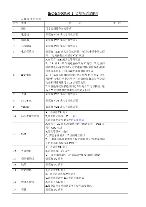
IEC/EN60950-1安规标准细则二、电气间隙及爬电距离1,L-N 间须至少满足基本绝缘2,保险丝两引脚间需至少满足基本绝缘3, 初次级电路之间,光藕初次级之间,变压器初次级之间(含初级绕组/初级PIN/初级铜箔对次级绕组/次级PIN/次级铜箔),Y电容初次级间均需满足双重绝缘或加强绝缘;初级带电部件同外壳外部可触及部位间需满足最少0。
4mm的穿透绝缘或双重绝缘/加强绝缘要求参考IEC60950-1 table 2H,2J,2L,基本绝缘,附加绝缘,加强绝缘(或双重绝缘)需满足以下要求(工作电压以250V AC 或354V峰值计算):基本绝缘/附加绝缘: 电气间隙CL:2。
mm Min, 爬电距离2。
5 mm Min双重绝缘/加强绝缘: 电气间隙CL:4.。
mm Min,爬电距离5.0 mm Min备注1:计算电气间隙及爬电距离,允许对内部零件施加10N的力备注2:计算电气间隙及爬电距离时,污染等级以2级计备注3:计算电气间隙及爬电距离时,物料级别通常为IIIb备注4:计算爬电距离时,允许用插值法三、高压及绝缘要求1备注:开关电源建议用DC电压进行高压测试.2、绝缘电阻IEC/EN60950-1对绝缘电阻无要求.四、正常温升(通常带满载进行测试)1,测试电压a,测试电压为电源电压的+6%- -10%,或b,额定电压为230V时,测试电压为230V的+/—10%,或c, 生产商指定的更宽的电压范围2,测试频率为50HZ 和/或60HZ3, 环境温度最大的环境温度为25度或生产商指定的更大值4, 绕阻允许的最高温度T《零件允许的最高温度+环境温度-生产商指定的最大的环境温度举例:B级绝缘物料允许的最高温度为120度, 测试的环境温度为25度,—若生产商没有指定最大的环境温度,则T《120+25-25,即T《120度(热偶法测试时T还需减10度)-若生产商指定最大的环境温度为40度,则则T《120+25—40,即T《105度(热偶法测试时T还需减10度)具体零件的温度限定见表4B5,正常温升测试的接收标准测试过程中,温度保险丝及电流保险丝不允许动作,零部件温度不得超出表4B的要求,测试后产品需立即通过高压测试五、异常测试(通常带满载进行测试)1, 测试电压a,测试电压为电源电压的+6%- —10%,或b,额定电压为230V时,测试电压为230V的+/-10%,或c, 生产商指定的更宽的电压范围2,测试频率为50HZ 和或60HZ3,环境温度最大的环境温度为25度或生产商指定的更大值4,测试方法a)开路或短路半导体零件和电容b)组合电路中会导致出现能量过分消耗的内部错误c)满足双重绝缘或加强绝缘的Y电容不必进行单一故障测试5,异常测试的接收标准异常测试过程中不允许出现:———火蔓延到设备外部,并且-——发出金属融化物——-外壳出现变形致使电气间隙及爬电距离不符要求-——A级绝缘物料温度超过150度,E级绝缘物料温度超过165度,B级绝缘物料温度超过175度,F 级绝缘物料温度超过190度,H级绝缘物料温度超过210度异常测试过程后不允许出现:—-——-高压失败六、接触电流(泄露电流)———可接触不见及电路没有连接到保护接地时,接触电流0.25mA Max-—-手持设备测试设备端子通过主保护接地端子时,接触电流0。
60950-1 1st和2nd版本变化

IEC60950-1 1st版本与IEC60950-1 2nd版本差异一)60950信息技术设备安规标准版本简介IEC60950 是国际电工委员会制定的信息技术设备的标准;EN60950是欧盟在IEC60950标准的基础上根据欧盟具体要求制定的标准;二)现在:IEC/EN 60950最新版本标准号是:IEC60950-1:2005 (2ed)EN60950-1:2006 (2ed)三)当前IEC/EN 60950系列标准(1) IEC/EN 60950-1:2006 (2ed)- IEC 勘误1发行日期2006年8月(2) IEC/EN 60950-21:2003 (1ed)远程馈电标准(3) IEC/EN 60950-22:2006(1ed)室外设备安装标准(4) IEC/EN 60950-23:2006 (1ed)大型数据存储设备标准四)IEC60950-1 1st版本升级为IEC60950-1 2nd版本IEC 60950-1的更新(1) 增加了新要求(2) 澄清了已经存在的要求(3) 增加了与其它标准的兼容性(4) 附表BB增加了标准更改清单1. 增加了新要求(1)音频放大器与IEC 60065标准的一致性要求(2.1.19)(2)电池的改进要求(4.3.8)(3)数据端口的限功率输出要求(3.5.4)(4)直流电源的详细要求(2.1.1.8)(5)电源的HICCUP模式,故障条件下的电压要求(6)气体放电灯启辉脉冲的绝缘要求(2.10.1.7, 2.10.2.1j, 2.10.3.5) (7)交流马达测试(B.6.3)2. 澄清了IEC 60950-1已有的要求(1) 球压测试:测试操作的高环境温度按制造商的规定(4.5.5)(2) 澄清了电缆分配系统的浪涌和脉冲的测试电压(7.4.2 and 7.4.3)(3) 固体绝缘要求1)光耦(2.10.5.4,图F.17)2)绕组的绝缘(2.10.5.11, 2.10.5.14 和附录U)3)绕组的线(2.10.5.12)4) TNV电路绕组器件上的瓷釉 (2.3.2.1 和2.10.5.13)(4) 限流源(2.5)(5) 机械强度(4.2.5 和4.2.6)(6) 非连续运行的要求(1.2.2, 1.7.3, 4.5.2 和5.3.8)(7) 铃流信号(M.3)(8) 与电源断接,单极绝缘(3.4.6)(9) 过压吸收器(避雷器)(1.5.9, Annex Q)初级电路的压敏电阻确定最小额定电压的更多要求(6.1.2.1)(10) 带多个连接设备的接触电流的测试操作(5.1.2 和5.1.7.2)(11) 连接器的电气间隙和爬电距离(2.10.3.1, 2.10.4.3 and G.6)(12) 增加和澄清了Ⅲ类和Ⅳ类设备的过压要求(2.10.3.2, G.1.1, AnnexZ)(13) 车载设备的外壳开孔(4.6.4)(14) 对保护连接导体的改进测试和要求(2.6.3.3 and 2.6.3.4)3. 增加了与其它标准的兼容性(1) 阴极射线管的要求与IEC 60065一致(4.2.8)(2) 污染等级2和3的电气间隙与IEC 60664-1 的要求一致(Table G.2)(3) X和Y桥接电容的要求与IEC 60384-14一致(1.5.6)(4) 不可分的绝缘片与IEC 61558-1标准要求一致(2.10.5.8, 2.10.5.9 和Annex AA)(5) 依照IEC 60085把热量等级分类(Tables 5D, B.1, B.2, C.1 AND U.2)4. IEC 60950-1的修改(1) 删去了对当地语言的要求(注释1.7.2.1)(2) 过流保护装置的外部要求。
IEC 609501 标准介绍
2020/10/11
IEC 609501 标准介绍
• 功能性絕緣 (FUNCTIONAL INSULATION) – 設備正常運作所需的絕緣 (不可
用於防止電擊, 但可用於減少可能的起火)
• 基本絕緣 (BASIC INSULATION) – 預防電擊的基本保護絕緣 • 補充絕緣 (SUPPLEMENTARY INSULATION) – 為減少在基本絕緣失效時的
2020/10/11
IEC 609501 标准介绍
▪ 認識產品安全的重要原理 ▪ 瞭解 IEC 60950-1:2005 的對產品安全的考量與要求重點 ▪ 提供產業於研發、設計、製造新產品時安全的重要基本概念及知識,
藉以減少後續產品認證時產品修改的困難, 影響產品進入市場的時程
2 TÜV Rheinland (Shanghai) Co., Ltd.
以上定義值皆由製造商自行宣告
8 TÜV Rheinland (Shanghai) Co., Ltd.
2020/10/11
IEC 609501 标准介绍
• 正常負載 (NORMAL LOAD) – 參酌製造商建議, 並考量設備在實際使用時
可能的最嚴苛操作條件
• 額定操作時間 (RATED OPERATING TIME) (製造商制定) • 額定休止時間 (RATED RESTING TIME) – 介於額定操作時間之間,設備關
IEC 609501 标准介绍
Information Technology Equipment – Safety –
Part 1: General Requirements IEC 60950-1 第二版 資訊設備一般要求
Mark Chen 陳信誠
德國萊茵集團
IEC609501安规要求介绍

IEC 60950-1:2001介紹
•4.2 操作人員不可碰觸下列電路或零件:
•- __•__E_L_V__電路的裸露零件, •- 具_•__危_險__電_壓__的裸露零件, •- ELV電路內只有_• _功__能_絕緣或_• _基_本__絕緣的零件或線 材,但符合規章條款2.1.1.3規定除外 •- 危險電壓電路內只有•_功__能__絕緣或•_基__本__絕緣的零件 或線材 •- __• _未_接__地__的導電零件與在危險電壓電路或ELV電路 內的零件,只有•__功_能__絕緣或_• _基__本_絕緣隔離
•- 避免高溫零件置放在__•_可__燃__液_體___上方
•- 當無法避免高溫零件暴露在__• _使__用__者_可__接___的區域時,須
提供標示以警告使用者
觸
IEC60950-1:2001介紹
•- Radiation hazards
•輻射的形式可能為音頻、無線電頻率、紅外線、高強度可見 光、凝聚光 、紫外線、離子化輻射等。 •如果設備內會釋出某種型式的輻射,則針對使用者及維修者 所能接受程度的輻射值,訂有規定。 • •降低輻射危險的方式有: •- 限制幅射源的_•__能__量__值 •- 提供_•__安_全__內__鎖__裝置 •- 當無法避免使用者可接觸可造成幅射危險的區域時,須提 供_•_標__示___以警告使用者
•一般降低能量危險的方式,如•_隔_____,• _屏____或• _安_全__內__鎖____
的防護。
離
蔽
IEC 60950-1:2001介紹
•- Fire • 在過載、零件失誤、絕緣崩潰、高阻抗或是連接器鬆脫 的情形下,其所造成的異常溫度有可能形成火災危險。然而,設 備內起火後不可散佈到起火點之鄰近區域及對設備外的區域造
iec 60950-1标准

iec 60950-1标准IEC 60950-1 是一项国际性的电气电子产品安全标准,其全称为"IEC 60950-1: Information technology equipment - Safety - Part 1: General requirements",中文译为"信息技术设备-安全-第1部分:通用要求"。
本文将对这一标准进行解读,包括标准的背景、范围、主要内容、适用领域、测试方法等方面的详细介绍。
一、标准背景IEC 60950-1 标准起源于对信息技术设备(ITE)的安全性要求的关注。
信息技术设备包括计算机、服务器、网络设备等,在其使用中需要满足一系列的电气、机械、热、辐射等方面的安全性要求,以确保用户和环境的安全。
二、标准范围IEC 60950-1 标准主要涵盖了信息技术设备的安全性要求,其中包括但不限于以下方面:电气安全:对设备内部电气元件、电路和电源的安全性要求。
机械安全:设备的机械结构、外壳和连接部分的设计和制造要求,以防止危险的机械伤害。
热安全:设备在正常使用和异常条件下的热特性,以确保不会引起火灾或热伤害。
辐射安全:设备的辐射特性,以防止对人体和其他设备的不良影响。
危险物质控制:对使用危险物质的限制和控制,以符合环保和人体健康的要求。
三、主要内容IEC 60950-1 标准主要包含以下内容:一般要求:对设备的整体设计、生产和测试的一般要求。
电气要求:包括电气元件的要求、绝缘和绝缘距离的要求等。
机械要求:设备的外壳、连接部分、机械强度和稳定性等的要求。
热要求:设备在正常和异常条件下的热性能要求。
辐射要求:设备产生的辐射和对辐射的抗干扰能力要求。
四、适用领域IEC 60950-1 标准适用于广泛的信息技术设备,包括但不限于:个人计算机和工作站服务器和数据中心设备网络设备,如路由器和交换机存储设备,如硬盘和光盘驱动器打印机和复印机视听设备,如电视、音响系统通信设备,如电话和传真机五、测试方法IEC 60950-1 标准中包含了一系列的测试方法,以确保设备在正常和异常条件下的安全性能。
iec60950对应国标

iec60950对应国标摘要:1.IEC 60950 简介2.我国对IEC 60950 的采纳情况3.IEC 60950 与国标的对应关系4.对我国电子信息产业的影响正文:一、IEC 60950 简介IEC 60950 是国际电工委员会(International Electrotechnical Commission,简称IEC)制定的一项关于安全标准和规范的国际标准,主要涉及音频、视频及多媒体设备和系统的安全要求。
该标准旨在保障使用者在操作这些设备和系统时的人身安全和设备安全。
二、我国对IEC 60950 的采纳情况我国一直积极参与IEC 60950 标准的制定和推广,并在国家标准化管理委员会的指导下,将其纳入我国的国家标准体系。
在我国,IEC 60950对应的国家标准为GB/T 18802.1-2011《消费音响设备和视频设备第1 部分:安全要求》。
三、IEC 60950 与国标的对应关系IEC 60950与我国国标GB/T 18802.1-2011 在很多方面具有一致性,但在某些细节上存在差异。
例如,IEC 60950 对设备的防护等级有较严格的要求,而我国国标则根据实际情况,对防护等级的要求略有放宽。
总体来说,我国国标在采纳IEC 60950 的基础上,结合国内实际,对部分内容进行了调整和完善。
四、对我国电子信息产业的影响IEC 60950 及其对应的国标对我国电子信息产业产生了积极影响。
首先,它为我国电子产品的设计、生产和检测提供了统一、明确的安全技术要求,有助于提高产品质量和安全性能。
其次,这一标准有助于推动我国电子产品与国际市场的接轨,提升我国电子产品在国际市场的竞争力。
IEC60950-1安规要求介绍讲义
IEC60950-1安规要求介绍讲义引言IEC60950-1是国际电工委员会(International Electrotechnical Commission)制定的安全标准,适用于信息技术设备(Information Technology Equipment,简称ITE)。
本文档将介绍IEC60950-1安规要求的基本概念和相关细节。
IEC60950-1的基本概念IEC60950-1是基于安全性原则的标准,其主要目的是保护使用者和操作员不受设备电气、机械和火灾等方面的危害。
该标准包含了一系列安全要求,以确保设备在正常使用中不会对人体造成伤害,并可以正常运行。
IEC60950-1的安全要求分为以下几个方面:1.电气安全:包括对设备内部电路的保护,以及对电气绝缘、接地和接触电流的要求。
2.机械安全:包括对设备结构和材料的要求,以及对可触及的部件和移动部分的安全保护。
3.火灾安全:包括对设备燃烧性能和防火措施的要求,以及对设备在故障条件下的火灾风险评估。
4.辐射安全:包括电磁辐射和光辐射的安全要求,以保护使用者和操作员的健康。
5.温度和湿度安全:包括对设备工作环境的温度和湿度要求,以确保设备的正常运行。
IEC60950-1安规的详细要求1. 电气安全要求1.1 设备内部电路的保护要求:•设备内部电路应采用双重绝缘或等效绝缘材料,以防止电气短路和触电风险。
•设备内部电路的绝缘电阻应满足规定的要求,以确保设备在正常工作和故障条件下不会引发危险。
•设备应具备过流和过压保护装置,以防止设备损坏和电气火灾。
1.2 电气绝缘和接地要求:•设备的外壳和外部连接部件应具备足够的机械强度和电气绝缘性能,以防止电气触电风险。
•设备应有可靠的接地装置,以确保设备在故障条件下能够及时排除电气故障。
2. 机械安全要求2.1 设备结构和材料的要求:•设备结构应有足够的机械强度和稳定性,以防止设备在正常使用过程中发生变形或损坏。
IEC 60950-1 标准介绍
9 TÜV Rheinland (Shanghai) Co., Ltd.
2019/10/22
重要定義 (裝置的移動性)
• 可移動式設備 (MOVABLE) • ≦18kg 且未加以固定 或
• 設備提供便於移動的方法讓操作者執行使用
• 手持式設備 (HAND-HELD) – 正常使用下用於手持(握)的可移動式設備或任何 設備的一部件
電力系統 屋內配線 無需電力裝置
5 TÜV Rheinland (Shanghai) Co., Ltd.
2019/10/22
安全的原理
• 安全設計的優先考慮順序 • 明定設計的準則用來將危險消除,減少或隔離 • 針對危險加以標示或指示
• 保護的對象 • 使用者(操作者) – 無能力識別危險, 但不故意製造危險狀況 • 維護/維修人員 – 針對顯著的危險, 具有預防危害自身及他人安全的 能力, 但無法預防非預期的危險
擊風險所應用附加於基本絕緣的獨立絕緣
• 雙重絕緣 (DOUBLE INSULATION) – 基本絕緣 + 補充絕緣 • 加強絕緣 (REINFORCED INSULATION) – 提供與雙重絕緣同等級的單一絕
緣系統以防護電擊
• 工作電壓 (WORKING VOLTAGE) – 零件或絕緣在正常使用狀況下的操作電壓 • 均方根值工作電壓 (RMS WORKING VOLTAGE) (含d.c.成分) • 峰值工作電壓 (PEAK WORKING VOLTAGE) (含d.c.成分及設備內部重複性產
7 TÜV Rheinland (Shanghai) Co., Ltd.
2019/10/22
重要定義 (裝置的電氣額定)
Power supply 安规认证 IEC60950-1

质量部/DQA
6
电源类产品安规认证要求 IEC 60950-1
• 能量有关的危险 (Energy related hazards)
• 危险能量:超过240VA的能量或潜在的不稳定的化学能量(Li-ion battery) • 防护措施: • 1,隔离&屏蔽,防止有危险能量的端子被导体桥接到,产生高温或火的危 险 • 2,提供一个安全互锁装置
• •
UL:UL是美国保险商实验室(Underwriter Laboratories Inc定的较大的民间机构。它是一个独立的、非营利的、为公共安全做试验的专 业机构。
•
CCC:中国强制认证(China Compulsory Certification)。目前被列入强制实施的产品有19类,132个品
质量部/DQA
2
电源类产品安规认证要求 IEC 60950-1
• • • • •
1. 安规认证的目的、意义及重要性 产品能安全,可靠,稳定的供消费者使用,是一个成功产品的前提。 安全认证是进入市场的必备条件之一。 消费者的选择决定了安规认证的必要性。 针对产品的自我检讨。
质量部/DQA
3
电源类产品安规认证要求 IEC 60950-1
质量部/DQA
8
电源类产品安规认证要求 IEC 60950-1
• 热的危险 (Heat related hazards)
• • • • • • • 烫伤 降低元件绝缘特性或损害功能而产生的电气危害或机械损伤 温度过高导致的火灾 防护措施: 1,开孔或增加Fan或heat-sink散热。 2,选用温度等级高的元件。 3,设置挡板隔离高温区。
质量部/DQA
9
电源类产品安规认证要求 IEC 60950-1
IEC60950-1 2005安规标准
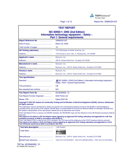
Page 1 of 12 Report No. 30880025.007 Myricom, Inc., 325 N. Santa Anita Ave., Arcadia CA 91006Page 2 of 12 Report No. 30880025.00710G-12U-SPINE-ENCL, 10G-7U-CLOS-ENCL, 10G-7U-SPINE-ENCL Ratings....................................................: Input: 100-240V, 50/60 Hz, 10A-5A (rating per input, up to 4 inputs)Page 3 of 12 Report No. 30880025.007General remarks:The test results presented in this report relate only to the object tested.This report shall not be reproduced, except in full, without the written approval of the Issuing testinglaboratory."(See Enclosure #)" refers to additional information appended to the report."(See appended table)" refers to a table appended to the report.Note: This TRF includes EN Group Differences together with National Differences and SpecialNational Conditions, if any. All Differences are located in the Appendix to the main body of this TRF. Throughout this report a comma (point) is used as the decimal separator.General product information:This test report is Amendment 2 to the original CB-report with document number 30880025.001 and the first amendmentCB report 30880025.004 and covers the addition of new line cards 10G-THRU-16Q, 10G-THRU-8M8ER, 10G-THRU-16WQP, 10G-SW32LC-16QP, 10G-S SW32LC-16ES, 10G-SW32LC-16EM. Each line card uses less power than linecards that have already been evaluated for the original report and subsequent amendment so no testing was performed as part of this investigation and the new line cards have been evaluated on a constructional basis only. Critical components within the line cards being added include Certified Class 1 lasers only.The product covered in this test report are LAN Switches with the model numbers: 10G-21U-CLOS-ENCL, 10G-21U-EDGE-ENCL, 10G-12U-CLOS-ENCL, 10G-12U-SPINE-ENCL, 10G-7U-CLOS-ENCL and 10G-7U-SPINE-ENCL. TheLAN Switch product comes with six different configuration codes: 10G-21U-CLOS-ENCL has the CLOS backplane boards, which accept eight 10G-2SW32LC line cards in the middle, one 10G-MONITOR-B in the top, and nearly any combination of the other line cards in the other slots. The 10G-21U-EDGE-ENCL has one 10G-MONITOR-B in the top,and the other slots accepts nearly any combination of the other line cards, excluding the 10G-2SW32LC line card (For details of line cards, see critical components list table 1.5.1). The 12U and 7U configurations are similar in functional configuration with the differences being the 12U is a smaller chassis intended for use with 2-4 power supplies and the7U is a still smaller chassis intended for use with 1-2 power supplies. The 12U configuration was tested per this investigation and it was determined via the test results and inspection that the data taken for the 21U is representativeof the 12U and 7U and as such the previously-measured 21 test results are applied to this report amendment.The enclosures contain a metal chassis, up four approved power supplies (different for each model), approved DC fans, a backplane, AC-Inlet/Filter and interface cards, which are all interchangeable. Model No. 10G-21U-CLOS-ENCL is a ‘21U high, 41-slot enclosure for switch networks up to 512 ports’ located on the rear panel of the unit. These ports areconnected to copper and fiber cables and there is no power available on these ports. All signals are AC coupled through470pF capacitorsDuring the testing the maximum power was generated by using resistive loads. Due to the expenses of each individualcard, a low-cost test configuration with these resistive loads cards generating 200W of power was used for thetemperature rise measurement and abnormal fault conditions.It should be noted that for the final configuration of the LAN Switches each individual card has two redundant temperature sensors which control the power to a card (thermal cut-out / power off at 60˚C). Also, the four DC fans at the back-side ofthe products are speed-adjustable depending on the temperature inside the LAN Switch enclosure. Individual temperature sensors are located on each line card and each fan controller PCBModel 10G-21U-CLOS-ENCL is intended to be fully operational with a minimum of three power supplies only. However,the four power supply configuration is intended for triple-AC systems( where there are three different sources of ACPage 4 of 12 Report No. 30880025.007 power), and the enclosure will continue to run will continue to run with one AC off and one power supply down. The unit contains; four fans, four power supplies and thirty cards – mixed.There are no connections to a Telecommunication Network (TNV).CDRH-Report for Optical Transceiver has to be provided by customer for US Approval.During the testing the maximum power was generated by using resistive loads. Due to the expenses ofeach individual card a low-cost test configuration with these resistive load cards, generating 200W ofpower, was used for the temperature rise measurements and abnormal fault conditions.Conditions of Acceptability:1.This unit is considered to operate under the conditions of:– Pollution Degree 2: Not sealed, not subjected to dust, dirt, and condensation– Equipment mobility: Rack mounted / fixed2. Rated ambient of 40°C at maximum rated loadPage 5 of 12 Report No. 30880025.007Page 6 of 12 Report No. 30880025.007 Summary of testing:Tests performed (name of test and test clause): = no testing performed for this amendment =Testing location:TUV Rheinland of North America, Inc.1279 Quarry Lane, Ste. A, Pleasanton, CA 94566Summary of compliance with National Differences:Comments:Summary of compliance with National Differences (for explanation of codes see below):AT, CA (temporary differences), DE, DK, FI, FR, GB, IT, JP, KR, NL, NO, PL, SE, SI, US (temporary differences).and Group Differences as listed at the end of this test reportExplanation of Codes:AT=Austria, CA-Canada, DE=Germany, DK=Denmark, FI=Finland, FR=France, GB=United Kingdom, IT=Italy,JP=Japan, KR=Korea, NL=The Netherlands, NO=Norway, PL=Poland, SE=Sweden, SI=Slovenia, US=United StatesThe following Attachments are integral part of this test report:= no attachments for this amendment =Page 7 of 12 Report No. 30880025.007Test item particulars..................................................:Equipment mobility....................................................: [] movable [] hand-held [] transportable[X] stationary [] for building-in [] direct plug-in Connection to the mains............................................: [] pluggable equipment [] type A [] type B[] permanent connection[X] detachable power supply cord[] non-detachable power supply cord[] not directly connected to the mainsOperating condition...................................................: [X] continuous[] rated operating / resting time:Access location .........................................................: [X] operator accessible[] restricted access locationOver voltage category (OVC) ...................................: [] OVC I [X] OVC II [] OVC III [] OVC IV[] other:Mains supply tolerance (%) or absolute mains supplyvalues .......................................................................:Tested for IT power systems ....................................: [X] Yes [] NoIT testing, phase-phase voltage (V) .........................: 230VClass of equipment ...................................................: [X] Class I [] Class II [] Class III[] Not classifiedConsidered current rating (A) ...................................:Pollution degree (PD) ...............................................: [] PD 1 [X] PD 2 [] PD 3IP protection class ....................................................: IPX0Altitude during operation (m) ....................................: 2000 mAltitude of test laboratory (m) ...................................: 2000 mMass of equipment (kg) ............................................: 98kgPossible test case verdicts:- test case does not apply to the test object.................:N/A- test object does meet the requirement.......................:P (Pass)- test object does not meet the requirement.................: F (Fail) Testing..........................................................................:Date of receipt of test item............................................:N/ADate(s) of performance of tests....................................:N/A[constructional check only, all test data is based onpreviously issued reports 30880025.001 and30880025.004, all changes per this amendment are eithernon-safety critical or editorial in nature only]Page 8 of 12 Report No. 30880025.007 1 GENERAL P1.5 Components P1.5.1 General Complies PComply with IEC 60950-1 or relevant component standard Refer to appended table 1.5.1(list of critical components)P1.5.2 Evaluation and testing of components All safety critical componentsare certified. All componentsare used within their specifiedratings, plastic materials,PCBs and wiring materialsare UL listed, non-certifiedcomponents were testedaccording to this standard.P 1.5.1 TABLE: List of critical components PObject/part No. Manufacturer/trademark Type/model Technical data Standard (Edition/ year)Mark(s) ofconformity1)1.) Power Supply (up to 4 each) Astec DS850-3 Input:100-240,50/60Hz, 10A;Output: +12V/70A,+3.3V/6AIEC/EN/UL60950-1UL 1449 (VDR’s)CSA, cULus, TUV2.) DC Fan (up to 8 each) Delta FFB1212EHE-F0012VDC3.0A –5.38 m3/minIEC/EN/UL 60950-1 VDE, CE, UL,CSA3.) DC Fan Controller board Myricom 05-2896 Minimumflammability rating:V-0,UL94 ULPage 9 of 12 Report No. 30880025.0074.) Internal wiring Various Various Rated 600V,105˚C,flammability ratingminimum VW-1 4wire gage type10070 from outputpower distributionboard to the powerback plane busbars (2 cables;3feet long) +/-12V.Wire gages forline/neutral/safetyground: type“1015” wire , 18gafor +12/- Backplane tosignal/power/fansto backplane 18ga to 24 ga .-- UL5.) Cards Myricom 10G-Monitor –B Minimumflammabilityrating:V-0UL94 UL6.) Cards Myricom 10G-SW32LC-16M Minimumflammabilityrating:V-0UL94 UL7.) Cards Myricom 10G-THRU-16M Minimumflammabilityrating:V-0UL94 UL8.) Cards Myricom 10G-SW32LC-16Q Minimumflammabilityrating:V-0UL94 UL9.) Cards Myricom 10G-THRU-16Q Minimumflammabilityrating;V-0UL94 UL10.) Cards Myricom 10G-SW32LC-8Q8ER Minimumflammabilityrating:V-0UL94 UL11.) Cards Myricom 10G-THRU-8Q8ER Minimumflammabilityrating:V-0UL94 UL12.) Cards Myricom 10G-SW32LC-8M8ER Minimumflammabilityrating:V-0UL94 UL13.) Cards Myricom 10G-THRU-8M8ER Minimumflammabilityrating:V-0UL94 UL14.) Cards Myricom 10G-SW32LC-8M8EM Minimumflammabilityrating:V-0UL94 UL15.) Cards Myricom 10G-THRU-8M8EM Minimumflammabilityrating:V-0UL94 UL16.) Cards Myricom 10G-SW32LC-16QP Minimumflammabilityrating:V-0UL94 ULPage 10 of 12 Report No. 30880025.007 17.) Cards Myricom 10G-THRU-16QP Minimumflammabilityrating:V-0UL94 UL18.) Cards Myricom 10G-SW32LC-8QP8ER Minimumflammabilityrating:V-0UL94 UL19.) Cards Myricom 10G-SW32LC-16ES Minimumflammabilityrating:V-0UL94 UL20.) Cards Myricom 10G-SW32LC-16EM Minimumflammabilityrating:V-0UL94 UL21.) Cards Myricom 10G-2SW32LC Minimumflammabilityrating:V-0UL94 UL22.) Cards Myricom 10G-FAN v1.0 Minimumflammabilityrating:V-0UL94 UL23.) Backplane left Myricom 10G-21U-CLOSMinimumflammabilityrating:V-0UL94 UL24.) Backplane right Myricom 10G-21U-CLOSMinimumflammabilityrating:V-0UL94 UL25.) Backplane left Myricom 10G-21U-EDGEMinimumflammabilityrating:V-0UL94 UL26.) Backplane right Myricom 10G-21U-EDGEMinimumflammabilityrating:V-0UL94 UL27.) Backplane left Myricom 10G-12U-CLOSMinimumflammabilityrating:V-0UL94 UL28.) Backplane right Myricom 10G-12U-CLOSMinimumflammabilityrating:V-0UL94 UL29.) Backplane left Myricom 10G-12U-EDGEMinimumflammabilityrating:V-0UL94 UL30.) Backplane right Myricom 10G-12U-EDGEMinimumflammabilityrating:V-0UL94 UL31.) Backplane left Myricom 10G-7U-CLOSMinimumflammabilityrating:V-0UL94 UL32.) Backplane right Myricom 10G-7U-CLOSMinimumflammabilityrating:V-0UL94 UL33.) Backplane left Myricom 10G-7U-EDGEMinimumflammabilityrating:V-0UL94 UL34.) Backplane right Myricom 10G-7U-EDGEMinimumflammabilityrating:V-0UL94 UL35.)Power Cord (U.K.) Volex 2922 250V, 10A, 13Afuse, 1mm2-- ASTA,BSIPage 11 of 12 Report No. 30880025.00736.) Power Cord (Germany / Europe) Volex orequivalent17850or equivalentRating: 300V, 10A,1.0mm2-- VDE, N, FI, S, D, I37.) Power Cord (U.S.) Volex 17504 125V, 15A, 14AWG-- UL,CSA38.) Power Cord (Japan) Feller 5330-440 125V,15A,2.0mm2-- DENTORI39.) Transceiver (10G-SW32LC-16Q/10G-THRU-16Q/10G-SW32LC-8Q8ER/10G-THRU-8Q8ER)Zarlink ZL60304-MKDA Class I M laser IEC/EN 60825-1 TUV, UL40.) Transceiver (10G-SW32LC-8Q8ER/10G-THRU-8Q8ER/10G-SW32LC-16Q/10G-THRU-16Q)Avago HFBR-7934EHZ Class I M laser IEC/EN 60825-1 TUV, UL41.) Transceiver (10G-SW32LC-8M8ER/10G-THRU-8M8ER/10G-SW32LC-8Q8ER/10G-THRU-8Q8ER/10G-SW32LC-8QP8ER)Finisar FLTX8511D3 Class I M laser IEC/EN 60825-1 TUV, UL42.) Transceiver (10G-SW32LC-8M8ER/10G-THRU-8M8ER/10G-SW32LC-8Q8ER/10G-THRU-8Q8ER/10G-SW32LC-8QP8ER)Finisar FTLX1411D3 Class I M laser IEC/EN 60825-1 TUV, ULPage 12 of 12 Report No. 30880025.00743.) Transceiver ( 10G-SW32LC-8M8ER/10G-THRU-8M8ER/10G-SW32LC-8Q8ER/10G-THRU-8Q8ER/10G-SW32LC-8QP8ER) Finisar FTLX1412D3BCL Class I laser EN 60825-1EN 60825-2EN 60950-1CSA 60950-1-03CDRHTUV, CSA, FDA44.) Transceiver (10G-SW32LC-8QP8ER/10G-SW32LC-16QP/10G-THRU-16QP)Zarlink ZL60505MJDA Class I M laser IEC/EN 60825-1 TUV, UL45.) Transceiver ( 10G-SW32LC-16ES) Finisar FTLX8571D3BCL Class I laser EN 60825-1EN 60825-2EN 60950-1CDRHTUV, FDA46.) Transceiver ( 10G-SW32LC-16ES) Finisar FTLX1471D3BCL Class I laser EN 60825-1EN 60825-2EN 60950-1CDRHTUV, FDA47.) Transceiver ( 10G-SW32LC-8QP8ER/10G-SW32LC-16QP/10G-THRU-16QP) Tyco Electronics 1985554-x1985861-x1-198554-01-1985861-01-1985861-1Class I M laser EN 60825-1EN 60825-2EN 60950-1CSA 60950-1-03CDRHTUV, CSA, FDA48.) InsulationTape/ used on theinternal chassisadjacent to metalbus bar3M Type 1206 Rated 155˚C UL510 UL49.) Temperature Sensor NationalSemiconductorLM74 3.0V/2.65V to5.5V, -10˚C to65˚C- -50.) Power Distribution Board Myricom 10G-POWERv1.1.Minimumflammabilityrating:V-0UL94 UL END of TEST REPORT。
压敏电阻在IEC 60950-1中的要求解析

STANDARD & APPLICATION引言浪涌被称为瞬态过电压,是电路中出现的一种短暂电流、电压波动,会对电子设备造成危害。
压敏电阻作为信息技术设备等产品中常见的抗雷击浪涌的元器件,可以有效防止这种危害。
但是压敏电阻的使用位置、选型不当都可能造成整机产品不满足安全标准要求。
本文分析了IEC 60950-1: 2013中对压敏电阻的要求,以期对压敏电阻的正确使用提供帮助。
1 压敏电阻相关定义解析电子电路中的浪涌保护元器件,也称为浪涌抑制器。
常见的浪涌抑制器包括电压敏感电阻器(VDR)、碳块、气体放电管(GDT)和其他一些具有非线性电压电流特性的半导体器件,如瞬态抑制二极管(TVS diode)。
其中电压敏感电阻器按其使用材料的不同可分为碳化硅压敏电阻器、金属氧化物压敏电阻器(MOV)、钛酸钡压敏电阻器等,其中以氧化锌为主的金属氧化物压敏电阻是目前开关电源中最广泛使用的浪涌保护元器件。
本文所分析的压敏电阻特指金属氧化物压敏电阻。
2 典型浪涌保护元器件介绍浪涌的保护元器件一般分为开关型和钳位型。
压敏电阻属于钳位型的典型代表,而气体放电管属于开关型的典型代表。
两者的区别也使得在使用时有极大不同。
2.1 压敏电阻压敏电阻实物和电路图中符号如图1,位号一般为VR、RV、X。
压敏电阻在正常电压下呈现高阻抗状态。
当外界浪涌电压超过压敏电阻电压时,压敏电阻会迅速击穿导通,工作电流急剧增大,将电压钳位;当外界电压恢复正常时,压敏电阻又恢复高阻抗状态(图2)。
压敏电阻响应时间快,一般用于电网电源的相线与中线之间。
但由于压敏电阻的电容值较大,不宜直接用于对高频电子系统的保护。
应用于相线与地之间时也要充分考虑漏电流。
2.2 气体放电管气体放电管实物和电路图符号如图3,位号一般为SG、SA。
气体放电管通常采用陶瓷封装,内部充满惰性气压敏电阻在IEC 60950-1中的要求解析Analysis on Request of Varistor in IEC 60950-1北京海关技术中心 武鹏 齐玮摘要阐述了压敏电阻和气体放电管的特性以及两者在开关电源单独或串联使用的情况;详细分析了 IEC 60950-1:2013对压敏电阻的要求,并结合型式试验时的不合格实例及整改方案来加以说明,有助于相关检测人员更好地理解标准。
iec60950产品设计结构简介安规要求安全距离 (1)

IEC 60950产品设计/结构简介IEC 60950 Design / Construction1. 绝缘方式 (Insulation, Clause 1.2.9)做为电击保护者基本绝缘 (Basic Insulation) –针对于电击之保护所提供之基本绝缘。
辅助绝缘 (Supplementary Insulation) –附加于基本绝缘上之独立性绝缘,以在基本绝缘失败时,可以减少电击之危险。
双重绝缘 (Double Insulation) - 基本绝缘加辅助绝缘之总称。
强化绝缘 (Reinforced Insulation) - 相等于双重绝缘之单层绝缘。
非做为电击保护者功能绝缘 (Fuctional Insulation) –产品正常使用时所必要之绝缘。
2. 直接插入式产品 (Direct Plug-In Unit)可以使用 UL 60950/CSA 60950 (I.T.E产品)或 UL1310/CSA223 (Class 2 Power Supply) 做验证。
美规插头尺寸须符合NEMA 1-15P (2-pin) or 5-15P (3-pin)。
插头拉力测试 (20 lb, 2 min each blade, UL 1310)。
插头推力测试 (30 lb each blade, 40 lb together, 1 min, UL 1310)。
插头至外壳边缘≥ 5.1mm(for UL),7.9 mm (CSA)。
输入线须耐 35 lb 拉力测试 (UL 1310)。
输出线须耐 20 lb 拉力测试 (UL 1310)。
3. 空间/沿面距离 (Clearance/Creepage Distances,Clause 2.10, Tables 2H, 2J, 2K and 2L)空间直线距离以峰值电压,根据 Table 2H (primary)、2J (primary additional)、2K (secondary) 计算。
IEC60950-1 2005安规标准

Page 1 of 12 Report No. 30880025.007 Myricom, Inc., 325 N. Santa Anita Ave., Arcadia CA 91006Page 2 of 12 Report No. 30880025.00710G-12U-SPINE-ENCL, 10G-7U-CLOS-ENCL, 10G-7U-SPINE-ENCL Ratings....................................................: Input: 100-240V, 50/60 Hz, 10A-5A (rating per input, up to 4 inputs)Page 3 of 12 Report No. 30880025.007General remarks:The test results presented in this report relate only to the object tested.This report shall not be reproduced, except in full, without the written approval of the Issuing testinglaboratory."(See Enclosure #)" refers to additional information appended to the report."(See appended table)" refers to a table appended to the report.Note: This TRF includes EN Group Differences together with National Differences and SpecialNational Conditions, if any. All Differences are located in the Appendix to the main body of this TRF. Throughout this report a comma (point) is used as the decimal separator.General product information:This test report is Amendment 2 to the original CB-report with document number 30880025.001 and the first amendmentCB report 30880025.004 and covers the addition of new line cards 10G-THRU-16Q, 10G-THRU-8M8ER, 10G-THRU-16WQP, 10G-SW32LC-16QP, 10G-S SW32LC-16ES, 10G-SW32LC-16EM. Each line card uses less power than linecards that have already been evaluated for the original report and subsequent amendment so no testing was performed as part of this investigation and the new line cards have been evaluated on a constructional basis only. Critical components within the line cards being added include Certified Class 1 lasers only.The product covered in this test report are LAN Switches with the model numbers: 10G-21U-CLOS-ENCL, 10G-21U-EDGE-ENCL, 10G-12U-CLOS-ENCL, 10G-12U-SPINE-ENCL, 10G-7U-CLOS-ENCL and 10G-7U-SPINE-ENCL. TheLAN Switch product comes with six different configuration codes: 10G-21U-CLOS-ENCL has the CLOS backplane boards, which accept eight 10G-2SW32LC line cards in the middle, one 10G-MONITOR-B in the top, and nearly any combination of the other line cards in the other slots. The 10G-21U-EDGE-ENCL has one 10G-MONITOR-B in the top,and the other slots accepts nearly any combination of the other line cards, excluding the 10G-2SW32LC line card (For details of line cards, see critical components list table 1.5.1). The 12U and 7U configurations are similar in functional configuration with the differences being the 12U is a smaller chassis intended for use with 2-4 power supplies and the7U is a still smaller chassis intended for use with 1-2 power supplies. The 12U configuration was tested per this investigation and it was determined via the test results and inspection that the data taken for the 21U is representativeof the 12U and 7U and as such the previously-measured 21 test results are applied to this report amendment.The enclosures contain a metal chassis, up four approved power supplies (different for each model), approved DC fans, a backplane, AC-Inlet/Filter and interface cards, which are all interchangeable. Model No. 10G-21U-CLOS-ENCL is a ‘21U high, 41-slot enclosure for switch networks up to 512 ports’ located on the rear panel of the unit. These ports areconnected to copper and fiber cables and there is no power available on these ports. All signals are AC coupled through470pF capacitorsDuring the testing the maximum power was generated by using resistive loads. Due to the expenses of each individualcard, a low-cost test configuration with these resistive loads cards generating 200W of power was used for thetemperature rise measurement and abnormal fault conditions.It should be noted that for the final configuration of the LAN Switches each individual card has two redundant temperature sensors which control the power to a card (thermal cut-out / power off at 60˚C). Also, the four DC fans at the back-side ofthe products are speed-adjustable depending on the temperature inside the LAN Switch enclosure. Individual temperature sensors are located on each line card and each fan controller PCBModel 10G-21U-CLOS-ENCL is intended to be fully operational with a minimum of three power supplies only. However,the four power supply configuration is intended for triple-AC systems( where there are three different sources of ACPage 4 of 12 Report No. 30880025.007 power), and the enclosure will continue to run will continue to run with one AC off and one power supply down. The unit contains; four fans, four power supplies and thirty cards – mixed.There are no connections to a Telecommunication Network (TNV).CDRH-Report for Optical Transceiver has to be provided by customer for US Approval.During the testing the maximum power was generated by using resistive loads. Due to the expenses ofeach individual card a low-cost test configuration with these resistive load cards, generating 200W ofpower, was used for the temperature rise measurements and abnormal fault conditions.Conditions of Acceptability:1.This unit is considered to operate under the conditions of:– Pollution Degree 2: Not sealed, not subjected to dust, dirt, and condensation– Equipment mobility: Rack mounted / fixed2. Rated ambient of 40°C at maximum rated loadPage 5 of 12 Report No. 30880025.007Page 6 of 12 Report No. 30880025.007 Summary of testing:Tests performed (name of test and test clause): = no testing performed for this amendment =Testing location:TUV Rheinland of North America, Inc.1279 Quarry Lane, Ste. A, Pleasanton, CA 94566Summary of compliance with National Differences:Comments:Summary of compliance with National Differences (for explanation of codes see below):AT, CA (temporary differences), DE, DK, FI, FR, GB, IT, JP, KR, NL, NO, PL, SE, SI, US (temporary differences).and Group Differences as listed at the end of this test reportExplanation of Codes:AT=Austria, CA-Canada, DE=Germany, DK=Denmark, FI=Finland, FR=France, GB=United Kingdom, IT=Italy,JP=Japan, KR=Korea, NL=The Netherlands, NO=Norway, PL=Poland, SE=Sweden, SI=Slovenia, US=United StatesThe following Attachments are integral part of this test report:= no attachments for this amendment =Page 7 of 12 Report No. 30880025.007Test item particulars..................................................:Equipment mobility....................................................: [] movable [] hand-held [] transportable[X] stationary [] for building-in [] direct plug-in Connection to the mains............................................: [] pluggable equipment [] type A [] type B[] permanent connection[X] detachable power supply cord[] non-detachable power supply cord[] not directly connected to the mainsOperating condition...................................................: [X] continuous[] rated operating / resting time:Access location .........................................................: [X] operator accessible[] restricted access locationOver voltage category (OVC) ...................................: [] OVC I [X] OVC II [] OVC III [] OVC IV[] other:Mains supply tolerance (%) or absolute mains supplyvalues .......................................................................:Tested for IT power systems ....................................: [X] Yes [] NoIT testing, phase-phase voltage (V) .........................: 230VClass of equipment ...................................................: [X] Class I [] Class II [] Class III[] Not classifiedConsidered current rating (A) ...................................:Pollution degree (PD) ...............................................: [] PD 1 [X] PD 2 [] PD 3IP protection class ....................................................: IPX0Altitude during operation (m) ....................................: 2000 mAltitude of test laboratory (m) ...................................: 2000 mMass of equipment (kg) ............................................: 98kgPossible test case verdicts:- test case does not apply to the test object.................:N/A- test object does meet the requirement.......................:P (Pass)- test object does not meet the requirement.................: F (Fail) Testing..........................................................................:Date of receipt of test item............................................:N/ADate(s) of performance of tests....................................:N/A[constructional check only, all test data is based onpreviously issued reports 30880025.001 and30880025.004, all changes per this amendment are eithernon-safety critical or editorial in nature only]Page 8 of 12 Report No. 30880025.007 1 GENERAL P1.5 Components P1.5.1 General Complies PComply with IEC 60950-1 or relevant component standard Refer to appended table 1.5.1(list of critical components)P1.5.2 Evaluation and testing of components All safety critical componentsare certified. All componentsare used within their specifiedratings, plastic materials,PCBs and wiring materialsare UL listed, non-certifiedcomponents were testedaccording to this standard.P 1.5.1 TABLE: List of critical components PObject/part No. Manufacturer/trademark Type/model Technical data Standard (Edition/ year)Mark(s) ofconformity1)1.) Power Supply (up to 4 each) Astec DS850-3 Input:100-240,50/60Hz, 10A;Output: +12V/70A,+3.3V/6AIEC/EN/UL60950-1UL 1449 (VDR’s)CSA, cULus, TUV2.) DC Fan (up to 8 each) Delta FFB1212EHE-F0012VDC3.0A –5.38 m3/minIEC/EN/UL 60950-1 VDE, CE, UL,CSA3.) DC Fan Controller board Myricom 05-2896 Minimumflammability rating:V-0,UL94 ULPage 9 of 12 Report No. 30880025.0074.) Internal wiring Various Various Rated 600V,105˚C,flammability ratingminimum VW-1 4wire gage type10070 from outputpower distributionboard to the powerback plane busbars (2 cables;3feet long) +/-12V.Wire gages forline/neutral/safetyground: type“1015” wire , 18gafor +12/- Backplane tosignal/power/fansto backplane 18ga to 24 ga .-- UL5.) Cards Myricom 10G-Monitor –B Minimumflammabilityrating:V-0UL94 UL6.) Cards Myricom 10G-SW32LC-16M Minimumflammabilityrating:V-0UL94 UL7.) Cards Myricom 10G-THRU-16M Minimumflammabilityrating:V-0UL94 UL8.) Cards Myricom 10G-SW32LC-16Q Minimumflammabilityrating:V-0UL94 UL9.) Cards Myricom 10G-THRU-16Q Minimumflammabilityrating;V-0UL94 UL10.) Cards Myricom 10G-SW32LC-8Q8ER Minimumflammabilityrating:V-0UL94 UL11.) Cards Myricom 10G-THRU-8Q8ER Minimumflammabilityrating:V-0UL94 UL12.) Cards Myricom 10G-SW32LC-8M8ER Minimumflammabilityrating:V-0UL94 UL13.) Cards Myricom 10G-THRU-8M8ER Minimumflammabilityrating:V-0UL94 UL14.) Cards Myricom 10G-SW32LC-8M8EM Minimumflammabilityrating:V-0UL94 UL15.) Cards Myricom 10G-THRU-8M8EM Minimumflammabilityrating:V-0UL94 UL16.) Cards Myricom 10G-SW32LC-16QP Minimumflammabilityrating:V-0UL94 ULPage 10 of 12 Report No. 30880025.007 17.) Cards Myricom 10G-THRU-16QP Minimumflammabilityrating:V-0UL94 UL18.) Cards Myricom 10G-SW32LC-8QP8ER Minimumflammabilityrating:V-0UL94 UL19.) Cards Myricom 10G-SW32LC-16ES Minimumflammabilityrating:V-0UL94 UL20.) Cards Myricom 10G-SW32LC-16EM Minimumflammabilityrating:V-0UL94 UL21.) Cards Myricom 10G-2SW32LC Minimumflammabilityrating:V-0UL94 UL22.) Cards Myricom 10G-FAN v1.0 Minimumflammabilityrating:V-0UL94 UL23.) Backplane left Myricom 10G-21U-CLOSMinimumflammabilityrating:V-0UL94 UL24.) Backplane right Myricom 10G-21U-CLOSMinimumflammabilityrating:V-0UL94 UL25.) Backplane left Myricom 10G-21U-EDGEMinimumflammabilityrating:V-0UL94 UL26.) Backplane right Myricom 10G-21U-EDGEMinimumflammabilityrating:V-0UL94 UL27.) Backplane left Myricom 10G-12U-CLOSMinimumflammabilityrating:V-0UL94 UL28.) Backplane right Myricom 10G-12U-CLOSMinimumflammabilityrating:V-0UL94 UL29.) Backplane left Myricom 10G-12U-EDGEMinimumflammabilityrating:V-0UL94 UL30.) Backplane right Myricom 10G-12U-EDGEMinimumflammabilityrating:V-0UL94 UL31.) Backplane left Myricom 10G-7U-CLOSMinimumflammabilityrating:V-0UL94 UL32.) Backplane right Myricom 10G-7U-CLOSMinimumflammabilityrating:V-0UL94 UL33.) Backplane left Myricom 10G-7U-EDGEMinimumflammabilityrating:V-0UL94 UL34.) Backplane right Myricom 10G-7U-EDGEMinimumflammabilityrating:V-0UL94 UL35.)Power Cord (U.K.) Volex 2922 250V, 10A, 13Afuse, 1mm2-- ASTA,BSIPage 11 of 12 Report No. 30880025.00736.) Power Cord (Germany / Europe) Volex orequivalent17850or equivalentRating: 300V, 10A,1.0mm2-- VDE, N, FI, S, D, I37.) Power Cord (U.S.) Volex 17504 125V, 15A, 14AWG-- UL,CSA38.) Power Cord (Japan) Feller 5330-440 125V,15A,2.0mm2-- DENTORI39.) Transceiver (10G-SW32LC-16Q/10G-THRU-16Q/10G-SW32LC-8Q8ER/10G-THRU-8Q8ER)Zarlink ZL60304-MKDA Class I M laser IEC/EN 60825-1 TUV, UL40.) Transceiver (10G-SW32LC-8Q8ER/10G-THRU-8Q8ER/10G-SW32LC-16Q/10G-THRU-16Q)Avago HFBR-7934EHZ Class I M laser IEC/EN 60825-1 TUV, UL41.) Transceiver (10G-SW32LC-8M8ER/10G-THRU-8M8ER/10G-SW32LC-8Q8ER/10G-THRU-8Q8ER/10G-SW32LC-8QP8ER)Finisar FLTX8511D3 Class I M laser IEC/EN 60825-1 TUV, UL42.) Transceiver (10G-SW32LC-8M8ER/10G-THRU-8M8ER/10G-SW32LC-8Q8ER/10G-THRU-8Q8ER/10G-SW32LC-8QP8ER)Finisar FTLX1411D3 Class I M laser IEC/EN 60825-1 TUV, ULPage 12 of 12 Report No. 30880025.00743.) Transceiver ( 10G-SW32LC-8M8ER/10G-THRU-8M8ER/10G-SW32LC-8Q8ER/10G-THRU-8Q8ER/10G-SW32LC-8QP8ER) Finisar FTLX1412D3BCL Class I laser EN 60825-1EN 60825-2EN 60950-1CSA 60950-1-03CDRHTUV, CSA, FDA44.) Transceiver (10G-SW32LC-8QP8ER/10G-SW32LC-16QP/10G-THRU-16QP)Zarlink ZL60505MJDA Class I M laser IEC/EN 60825-1 TUV, UL45.) Transceiver ( 10G-SW32LC-16ES) Finisar FTLX8571D3BCL Class I laser EN 60825-1EN 60825-2EN 60950-1CDRHTUV, FDA46.) Transceiver ( 10G-SW32LC-16ES) Finisar FTLX1471D3BCL Class I laser EN 60825-1EN 60825-2EN 60950-1CDRHTUV, FDA47.) Transceiver ( 10G-SW32LC-8QP8ER/10G-SW32LC-16QP/10G-THRU-16QP) Tyco Electronics 1985554-x1985861-x1-198554-01-1985861-01-1985861-1Class I M laser EN 60825-1EN 60825-2EN 60950-1CSA 60950-1-03CDRHTUV, CSA, FDA48.) InsulationTape/ used on theinternal chassisadjacent to metalbus bar3M Type 1206 Rated 155˚C UL510 UL49.) Temperature Sensor NationalSemiconductorLM74 3.0V/2.65V to5.5V, -10˚C to65˚C- -50.) Power Distribution Board Myricom 10G-POWERv1.1.Minimumflammabilityrating:V-0UL94 UL END of TEST REPORT。
IEC60950-1

IEC 60950-1:2001介绍
Materials and components hazards
在设备内所使用的材料及零件,须给予适当的选择及安置,故 其不会在正常或异常工作时,导致上述的危险。
Scope:
IEC 60950规章主要是适用于mains-powered or battery –powered 信息产品(含商业电子设备)及其 外围产品,请额定电压低于600V.
1. 一般安全原理
在IEC/EN 60950-1的条文内,主要是在防止人体受到
下述危险的伤害, 人体泛指使用者及服务人员此二种类
型的人:
危險的種類 電殛(Electric shock) 危險能量(Energy hazards) 火災(Fi re) 機械及熱的危險(Mechanical and heat hazards) 幅射危險(Radiation hazards) 化學的危險(Chemical hazards) 材料及零件(Materials and components)
IEC60950-1
IEC 60950-1:2001介绍
IEC60950-1 安规要求介绍 讲师
Amy Lin 林丽芬
IEC 60950-1:2001介绍 本讲义主要内容: 1.一般安全原理 2.定义 3.General Requirements 4.危险的防护 5.物理特性的要求
IEC 60950-1:2001介绍
降低火灾危险的方式有: - 提供__过__电__流___保护 - 结构使用的材料具有适当的__燃__烧____等级 - 选用不会因__过__热___导致燃烧的零件及易燃材料 - 限制易燃材料的使用__数__量__ - 将易燃材料与燃烧源_隔__离___ - 使用_壳__罩____或__挡__墙___抑制火焰扩散至设备外 - 使用具适当的__燃__烧__等级壳罩,以抑制火焰扩散至设备外
iec60950-1标准介绍

22 TÜV Rheinland (Shanghai) Co., Ltd.
2021操作 • 安裝 (如:電源連接, 設備互連, 電工法規) • 運輸 • 儲存 • 撰寫語言
• 空間 (CLEARANCE) – 經由空氣所量測的最短距離 • 沿面(爬行)距離 (CREEPAGE DISTANCE) – 沿絕緣表面所量測的最短距離 • 防護界面 (BOUNDING SURFACE) – 電氣外殼的表面 • 固態絕緣 (SOLID INSULATION) – 透過兩相對的表面以提供絕緣的材料
能暴露的危險及減低對自己及其他人風險的方法
• 功能性接地 (FUNCTIONAL EARTHING) – 不用於安全的目的 • 保護性接地導體 (PROTECTIVE EARTHING CONDUCTOR) – 連接設備內的主保
護性接地端子到建築物安裝的接地點, 位於建築物配線中或電源線中
• 保護性等電位聯結導體 (PROTECITVE BOUNDING CONDUCTOR) – 設備中的導
(OPERATOR) ] – 在正常操作狀況下設備的下列部位:
• 無需使用工具即可觸及 • 提供操作者達成接觸所需的工具或手段 • 不論是否需要工具, 使用者被指導進入 • 維護觸及區 (SERVICE ACCESS AREA) – 非操作者觸及區, 維護人員必需進入設
備的部位 (甚至在設備運作時)
備的一部件
• 可攜式設備 (TRANSPORTABLE) – 使用者經常攜帶的可移動式設備 • 靜置式設備 (STATIONARY) – 非移動式設備 • 直插式(插牆式)設備 (DIRECT PLUG-IN) – 設備無需使用電源供應線, 其電源插
- 1、下载文档前请自行甄别文档内容的完整性,平台不提供额外的编辑、内容补充、找答案等附加服务。
- 2、"仅部分预览"的文档,不可在线预览部分如存在完整性等问题,可反馈申请退款(可完整预览的文档不适用该条件!)。
- 3、如文档侵犯您的权益,请联系客服反馈,我们会尽快为您处理(人工客服工作时间:9:00-18:30)。
或任何类型设备的一个部件
2020/3/3
18
设备级别
固定:Stationary equipment which is fastened or otherwise secured at a specific location.
直插式:预定使用中不使用电源线,电源插头 和设备外壳构成一整体、其重量是靠墙上插 座来承载的设备。
2020/3/3
3
IEC 60950-1:2001介紹
- Electric shock
電殛的發生情形是因為有電流通過人體,只要有數毫安培的電 流,即可對正常健康人造成影響,並且有可能因不自覺地反應而 造成間接性危險。當然,更大的電流會造成更危險的情形。一 般而言,在乾燥情形下,小於40Vpeak或60Vdc的電壓,通常視為 不具危險的電壓。但是,可被觸碰的零件或是提把皆應接至大 地或是將其適當地隔離之。
2020/3/3
6
IEC 60950-1:2001介紹
- Mechanical hazards 機械的危險是因下列原因而產生: - 設備的機構穩定度及結構穩固 - 避免結構上銳邊尖角 - 受危險可動零件所傷 - 受陰極射線管或高壓燈泡爆裂的碎片所傷 降低機械的危險的方式有: - 設備的銳邊或銳角___圓__弧_化__ - 提供___安_全__內__鎖___裝置 - 提供___防__護_罩___ - 適當的____穩_定__度____設計 - 選用陰極射線管及高壓燈泡具___防__爆___功能 - 當無法避免使用者會因接觸而造成機械危險的區域時須 提供___標_示___以警告使用者
• (短时工作):正常负载下,在一段规定的时间 内进行工作,这种工作是从设备处在冷态条件下 开始,在每一段工作时间之间相隔有足够的时间 使设备冷却到室温。
• 测试的时候影响负载的模拟。
2020/3/3
17
• 移动性 设备级别
• 可移动:
--质量小于或等于18Kg且未固定的设备.或 者
--装有滚轮、小脚轮或其他装置,便于操作 人员按完成预定应用的需要来移动的设备
2020/3/3
24
LCC-Part2
• Limits of available energy ∙For voltage<450V peak or dc,
-Capacitance≤0.1μF and was recorded in μF
∙For voltage=(450,15,000)V pk or dc,
-Stored charge ≤45 μC and was recorded in μC = (μF)V
∙For voltage>15,000V peak or dc, -Available energy ≤350 mJ and was recorded in
12
UL60950 产品范围
• 记帐机,簿记机,计算器,现金出纳机,复印 机,数据电路终端设备,数据预处理设备, 数据处理设备,数据终端设备,听写设备, 碎纸机,复制机,电动绘图机,消磁器,传真 机,按键电话系统,、、、
2020/3/3
13
附加要求
• 对于下列设备,可能需要在本标准所规定的那些安 全要求中附加一些要求:
2020/3/3
20
SELV电路safety extra-low voltage circuit
• A SECONDARY CIRCUIT which is so designed and protected that under
• Normal operating conditions,and • -Voltages not exceed 42.4V pk or 60V
安装固定:预定安装在预先准备好的凹座内的 设备,例如装在墙壁内或类似安装位置内的 设备。
注:通常,嵌装式设备并不是所有的侧面都具 有外壳,因为在安装好之后,有的侧面就得 到了保护。
2020/3/3
19
电路的概念
• 1、SELV电路safety extra-low voltage circuit安全特低电压电路 • 2、LCC电路Limited current circuit • 限制电流电路 • 3、ELV电路extra-low voltage • 特低电压 • 4、Hazardous voltage • 危险电压 • 5、LPS电源输出Limited power source • 受限电源 • 6、TNV电路telecommunication network voltage circuit • 通信网络电压电路
2020/3/3
7
IEC 60950-1:2001介紹
- Heat hazards
設備正常工作下,因下列因素(高溫)導致熱的危險: - 因觸碰到高溫零件而造成的傷害 - 設備的絕緣能力及安全零件被破壞 - 可燃液體燃燒起來
降低熱的危險的方式有: - 避免高溫零件暴露在 ___使_用__者__可_接__觸___ 的區域 - 避免高溫零件置放在___可__燃_液__體___上方 - 當無法避免高溫零件暴露在__使__用_者__可__接_觸___的區域時,須 提供標示以警告使用者
• Recognized(QQGQ2/8,NWGQ2/8)认可
• 这个类别下的设备在某些结构是不完整的或 在性能上受到限制,不能直接独立安装在现 场,而是作为一个完整设备中的零部件而使
用的。
2020/3/3
16
设备级别
• (连续动作):在正常负载条件下不限时间的工作
• (间歇运作):在规定的一连串相同的循环周期 内进行工作,每一个周期由正常负载条件下的一 段工作时间和紧接着设备断电或空转的一段间歇 时间组成
2020/3/3
10
基本概念
• 基本概念与关键元件
2020/3/3
11
UL60950 Scope 产品范围
• 本标准适用于电网电源供电的电池供电 的、额定电压不超过600V的信息技术 设备,包括电气事务设备和与之相关的 设备。
• 设计使用交流电网电源作为通信传播媒 介的信息技术设备。
2020/3/3
2020/3/3
22
LCC限流电路
• 限流电路 • 作了适当的设计和保护的电路,使得在
正常工作条件下和单一故障条件下,能 从该电路流出的电流是非危险的电流。 • 注:正常工作条件下和单一故障条件下 的电流限值在2.4中作也规定。
2020/3/3
23
LCC-Part1
• The available current(A)shall not exceed the limits under both normal operating conditions and in the event of a single failure -For frequency not exceeding 1 kHz ∙A pk=V pk/2000Ω<0.7mA pk ∙A dc=V dc/2000Ω<2.0mA dc -For frequency above 1kHz ∙A pk=V pk/2000Ω<0.7mA X freq.(in kHz), ∙But available current(A)shall not exceed 70mA
IEC60950-1 安规要 求简介
IEC 60950-1:20General Requirements
•危險的防護
•物理特性的要求
2020/3/3
2
IEC 60950-1:2001介紹
1. 一般安全原理
在IEC/EN 60950-1的條文內,主要是在防止人體受到 下述危險的傷害, 人體泛指使用者及服務人員此二種類 型的人:
降低火災危險的方式有: - 提供___過__電_流___保護 - 結構使用的材料具有適當的___燃__燒___等級 - 選用不會因__過__熱___導致燃燒的零件及易燃材料 - 限制易燃材料的使用__數__量__ - 將易燃材料與燃燒源__隔__離__ - 使用__殼__罩___或__擋__牆___抑制火燄擴散至設備外 - 使用具適當的__燃__燒__等級殼罩,以抑制火燄擴散至設備外
一般降低能量危險的方式,如__隔_離___,_屏__蔽__或___安_全__內__鎖__的 防護。
2020/3/3
5
IEC 60950-1:2001介紹
- Fire 在過載、零件失誤、絕緣崩潰、高阻抗或是連接器鬆脫
的情形下,其所造成的異常溫度有可能形成火災危險。然而,設 備內起火後不可散佈到起火點之鄰近區域及對設備外的區域造 成危險。
dc • Single fault conditions,
• 1.For t=(0,200ms),V≤71V pk or 120V dc • 2.For t=(0.2s, ∞),V≤42.4V pk or 60V dc
2020/3/3
21
SELV 电路safety extra-low voltage circuit
2020/3/3
9
IEC 60950-1:2001介紹
- Chemical hazards
有毒化學物質本身及其蒸汽,如果人體直接接觸到,則會造成 傷害。因此,設備的設計,亦應避免在正常操作及異常操作情 況下,產生此類的化學危險。
降低化學危險的方式有: - 避免使用會因接觸或吸入會導致危險之結構材料及易燃 材料 - 當無法避免使用者因接觸而造成幅射危險的區域時,須 提供標示以警告使用者
2020/3/3
15
UL60950-1 Product category 产品类别
• LISTED(QQGQ/7,NWGQ/7):列名
• 这个类别覆盖额定600伏及以下的,用于配 合信息技术设备包括电子商务设备使用的电
源产品。与这类电源配套的成品是包含在信
