典型数字控制系统
控制系统分类

控制系统分类控制系统分类控制系统是指能够对某个对象或过程进行监测、判断、调节和控制的一种技术体系。
根据不同的分类标准,可以将控制系统分为多种类型。
本文将从不同的角度出发,对控制系统进行分类。
一、按照控制对象分类1.机械控制系统机械控制系统是指通过机械传动来实现对某个对象或过程进行监测、判断、调节和控制的一种技术体系。
例如,汽车发动机的传动系统就是一种典型的机械控制系统。
2.电气控制系统电气控制系统是指通过电气信号来实现对某个对象或过程进行监测、判断、调节和控制的一种技术体系。
例如,家庭电器中的温度调节器就是一种典型的电气控制系统。
3.液压与气动控制系统液压与气动控制系统是指通过液体或气体来实现对某个对象或过程进行监测、判断、调节和控制的一种技术体系。
例如,工业生产中常用的液压升降平台就是一种典型的液压与气动控制系统。
二、按照控制方式分类1.开环控制系统开环控制系统是指在控制过程中没有反馈信号的一种技术体系。
例如,家庭电器中的电风扇就是一种典型的开环控制系统。
2.闭环控制系统闭环控制系统是指在控制过程中有反馈信号的一种技术体系。
例如,汽车中的自动驾驶系统就是一种典型的闭环控制系统。
三、按照控制对象数量分类1.单变量控制系统单变量控制系统是指只对一个变量进行监测、判断、调节和控制的一种技术体系。
例如,家庭电器中的温度调节器就是一种典型的单变量控制系统。
2.多变量控制系统多变量控制系统是指对多个变量进行监测、判断、调节和控制的一种技术体系。
例如,工业生产中常用的化工生产过程就是一种典型的多变量控制系统。
四、按照实现方式分类1.模拟式控制系统模拟式控制系统是指通过模拟电路来实现对某个对象或过程进行监测、判断、调节和控制的一种技术体系。
例如,工业生产中常用的模拟式控制系统就是一种典型的模拟式控制系统。
2.数字式控制系统数字式控制系统是指通过数字电路来实现对某个对象或过程进行监测、判断、调节和控制的一种技术体系。
中控DCS基础知识课件

电网调度管理
02
利用DCS系统实现电网的实时调度管理,提高电网运行效率和
供电质量。
新能源接入与控制
03
DCS系统可实现对风能、太阳能等新能源发电设备的接入与控
制,推动清洁能源的广泛应用。
其他行业应用前景展望
智能制造领域
随着工业4.0的发展,DCS系统将在智能制造领域发挥重要作用, 实现生产过程的自动化、智能化和网络化。
发展历程
DCS自1975年问世以来,已经经历了四十多年的发展历程。从 最初的模拟仪表控制系统到数字化控制系统,再到现在的智能 化控制系统,DCS系统的功能和性能都得到了极大的提升。
中控DCS特点及优势
技术特点
中控DCS系统采用了先进的控制算法、高 速数据处理技术和可靠的硬件设计,具有 高度的实时性、稳定性和可靠性。
在不同负载下进行压力测试,观察系统性能表现。
常见故障排查技巧
观察法
通过观察设备指示灯、显示屏等信息, 判断设备状态及故障原因。
替换法
将疑似故障的设备或部件替换为正常 设备或部件,观察系统是否恢复正常 运行。
逐步排查法
从系统输入端开始逐步排查,检查信 号传输路径中的每一个环节,直至找 到故障点。
利用专业工具
市场需求
随着工业自动化程度的不断提高和智能制造的深入推进,中控DCS系统的市场需求 不断增长。未来,中控DCS系统将继续向着智能化、网络化、集成化的方向发展, 满足工业领域对于高效、安全、环保等方面的需求。02硬件组来自与结构控制器类型及功能
DCS控制器类型
主要包括冗余控制器、单控制器等 类型。
控制器功能
智慧城市建设
DCS系统可应用于智慧交通、智慧水务、智慧能源等智慧城市建 设领域,提高城市运行效率和居民生活质量。
计算机控制技术考试重点

• • • • • • • • • • • • • •
1.计算机控制系统是由哪几部分组成的? 计算机控制系统是由哪几部分组成的? 在计算机控制系统中,如何选定采样周期T 2.在计算机控制系统中,如何选定采样周期T? 以某一控制系统( 温度控制系统)为例, 3.以某一控制系统(如:温度控制系统)为例,简述计算机在 一个控制周期内应完成哪些事情? 一个控制周期内应完成哪些事情? 操作指导、DDC和SCC系统工作原理如何 系统工作原理如何? 4.操作指导、DDC和SCC系统工作原理如何?它们之间有何区别 和联系? 和联系? 5.计算机控制系统的典型形式有 计算机控制系统的典型形式有——? 5.计算机控制系统的典型形式有 ? 6.工业控制计算机的总线分为 工业控制计算机的总线分为——? 6.工业控制计算机的总线分为 ? 7.与双积分型A/D相比 逐次逼近型A/D 与双积分型A/D相比, A/D的精度 、速度 、 7.与双积分型A/D相比,逐次逼近型A/D的精度 8.步进电机单三拍控制方式的输出字为 8.步进电机单三拍控制方式的输出字为 、 、 。 9.一般情况下 一般情况下, 算法。 9.一般情况下,串级控制的副回路采用 算法。 10.对单位速度输入 对单位速度输入, 10.对单位速度输入,设计最少拍无纹波控制器的必要条件 是 。 11.RS232规定的电气特性是什么 规定的电气特性是什么? 11.RS232规定的电气特性是什么? 12.什么是数字滤波器?列出三种数字滤波算法。 12.什么是数字滤波器?列出三种数字滤波算法。 什么是数字滤波器 13.对单位速度输入 对单位速度输入, 13.对单位速度输入,设计最少拍无纹波控制器的必要条件 是 。 14.ADC0809的OE管脚起什么作用 管脚起什么作用? 14.ADC0809的OE管脚起什么作用?
DCS控制系统及典型控制方案
DCS控制系统及典型控制方案常洪娟⏹集散系统Distributed Control system,简称DCS⏹集散系统的含义是,利用微处理机或微型计算机技术对生产过程进行集中管理和分散控制的系统⏹技术基础微型计算机⏹应用对象生产过程⏹技术特点集中操作、管理和分散控制DCS的产生⏹50年代前,过程控制主要使用气动仪表⏹50年代后期,出现电动单元组合仪表⏹一次表留在现场的变送器和执行机构⏹二次表集中在中控室的调节与显示表⏹60年代,开始使用直接数字控制(DDC),由一台过程控制计算机对数百个回路进行控制,在带来很多优点的同时,出现了“危险集中”。
⏹70年代中期,出现集散系统。
操作更方便,集中管理,功能分散、任务分散的同时,危险也分散DCS发展历程(一)⏹1975年至1980年,初创期,代表产品有⏹Honeywell TDC2000⏹横河电机CENTUM⏹Foxboro SPECTRUM⏹技术特征:⏹带显示器的操作站与过程控制单元分离,实现了集中操作、分散控制⏹在硬件制造和软件设计上采用了冗余技术⏹引入了网络通信技术,以数据传输通道连接各组成部分,实现了系统内的资源共享DCS发展历程(二)⏹1980年至1985年,成熟期,代表产品有⏹Honeywell TDC3000(LCN)⏹横河电机CENTUM-A,-B,-D⏹Rosemount RS3⏹技术特征:⏹引入了局域网技术,通信范围扩大,数据传送速率大大提高,但各厂家网络通信机制各不相同。
⏹主要采用16位CPU,控制功能增强。
⏹操作站开始兼有简单的管理功能⏹采用上位机以完成一些复杂运算和较强的管理功能DCS发展历程(三)⏹1985年以后,扩展期,代表产品有⏹Foxboro I/A-S⏹Honeywell TDC3000X,TPS⏹横河电机CENTUM-XL,-uXL,-CS⏹Fisher-Rosemount Delta-V⏹技术特征:⏹系统开始走向开放,不同制造厂的产品可以相互连接、相互通信和进行数据交换。
楼控-DDC(直接数字控制器)的介绍

楼控-基础培训-DDC(直接数字控制器)的介绍DDC系统介绍何谓DDCDDC(Direct Digital Control)意指「直接数字控制」。
近几年来,它代替了传统控制组件,如温度开关、接收控制器或其它电子机械组件等,成为各种建筑环境控制的通用模式。
DDC系统是利用微信号处理器来做执行各种逻辑控制功能,它主要采用电子驱动,但也可用传感器连接气动机构。
所有的控制逻辑均由微信号处理器,并以各控制器为基础完成,这些控制器接收传感器,常用融点或其它仪器传送来的输入信号,并根据软件程序处理这些信号,再输出信号到外部设备,这些信号可用于启动或关闭机器,打开或关闭阀门或风门,或按程序执行复杂的动作。
这些控制器可用手操作中央机器系统或终端系统。
何谓DDC终端系统一个终端系统是机械系统中用于服务一单独区域的组成部分,例如:一个单独的风机盘管控制器、VAV控制器、热泵控制器…等。
DDC终端是DDC的应用系统。
这是应用于商业建筑的控制工业的新发展,它可提供整个建筑暖通空调系统的运行情况。
DDC终端系统的控制水平信息处理与控制的水平取决于机器设备的形式,如VAV终端,其操作系统通过设置是否需加热或降温的气流温度设定点,根据气流流量和设置最大最小的流量值,操作可设定的工作时间表,假日时间表,允许忽略时间,如装有排气感温棒,还可根据排气温度。
它可监控每个VAV的风扇运行时间和管道加热器工作时间。
其它终端系统也是类似的,但对系统的影响有所不同。
DDC系统的主要优点专门使用的DDC系统具有很多优点,以下列出其中最重要的几点:1. 操作:终端DDC系统是建筑物管理的有力工具,它的操作系统可方便地管理一个或多个岗位,可及时按客户要求或程序要求作出反应,DDC系统允许控制器在操作时间内同时具有其它功能,这一点是区别于传统系统的。
DDC系统可以单个终端获得整个建筑操作的所有信息,这就具有很强的故障诊断能力。
2. 降低费用:一个良好设计的DDC系统可在能源和人力方面降低费用。
DDC控制器 直接数字控制系统(Direct Digital Control简称DDC),
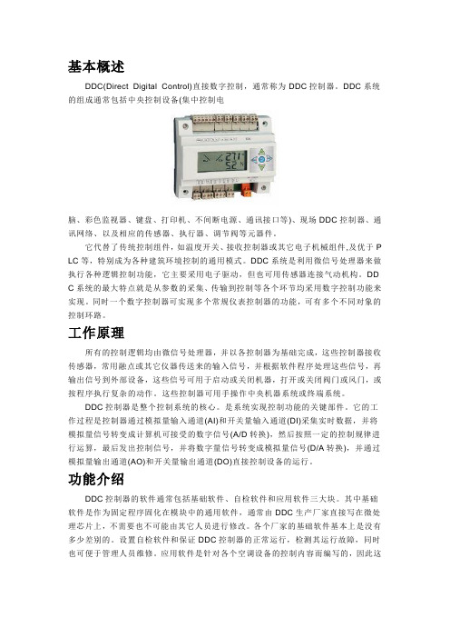
基本概述DDC(Direct Digital Control)直接数字控制,通常称为DDC控制器。
DDC系统的组成通常包括中央控制设备(集中控制电脑、彩色监视器、键盘、打印机、不间断电源、通讯接口等)、现场DDC控制器、通讯网络、以及相应的传感器、执行器、调节阀等元器件。
它代替了传统控制组件,如温度开关、接收控制器或其它电子机械组件,及优于P LC等,特别成为各种建筑环境控制的通用模式。
DDC系统是利用微信号处理器来做执行各种逻辑控制功能,它主要采用电子驱动,但也可用传感器连接气动机构。
DD C系统的最大特点就是从参数的采集、传输到控制等各个环节均采用数字控制功能来实现。
同时一个数字控制器可实现多个常规仪表控制器的功能,可有多个不同对象的控制环路。
工作原理所有的控制逻辑均由微信号处理器,并以各控制器为基础完成,这些控制器接收传感器,常用融点或其它仪器传送来的输入信号,并根据软件程序处理这些信号,再输出信号到外部设备,这些信号可用于启动或关闭机器,打开或关闭阀门或风门,或按程序执行复杂的动作。
这些控制器可用手操作中央机器系统或终端系统。
DDC控制器是整个控制系统的核心。
是系统实现控制功能的关键部件。
它的工作过程是控制器通过模拟量输入通道(AI)和开关量输入通道(DI)采集实时数据,并将模拟量信号转变成计算机可接受的数字信号(A/D转换),然后按照一定的控制规律进行运算,最后发出控制信号,并将数字量信号转变成模拟量信号(D/A转换),并通过模拟量输出通道(AO)和开关量输出通道(DO)直接控制设备的运行。
功能介绍DDC控制器的软件通常包括基础软件、自检软件和应用软件三大块。
其中基础软件是作为固定程序固化在模块中的通用软件,通常由DDC生产厂家直接写在微处理芯片上,不需要也不可能由其它人员进行修改。
各个厂家的基础软件基本上是没有多少差别的。
设置自检软件和保证DDC控制器的正常运行,检测其运行故障,同时也可便于管理人员维修。
数字控制理论及应用(讲稿)第二章 数字控制系统的组成

第二章 数字控制系统的组成第一节 数字控制系统硬件及软件组成一、 硬件部分计算机控制系统的硬件包括主机、接口电路、过程输入/输出通道、外部设备、操作台等。
1、主机它是过程计算机控制系统的核心,由中央处理器(CPU)和内存储器组成。
主机根据输入通道送来的被控对象的状态参数,按照预先制定的控制算法编好的程序,自动进行信息处理、分析、计算,并作出相应的控制决策,然后通过输出通道发出控制命令,使被控对象按照预定的规律工作。
2、接口电路它是主机与外部设备、输入/输出通道进行信息交换的桥梁。
在过程计算机控制系统中,主机接收数据或者向外发布命令和数据都是通过接口电路进行的,接口电路完成主机与其它设备的协调工作,实现信息的传送。
3、过程输入/输出通道过程输入输出(I/O)通道在微机和生产过程之间起着信号传递与变换的纽带作用,它是主机和被控对象实现信息传送与交换的通道。
模拟量输入通道把反映生产过程或设备工况的模拟信号转换为数字信号送给微机;模拟量输出通道则把微机输出的数字控制信号转换为模拟信号(电压或电流)作用于执行设备,实现生产过程的自动控制。
微机通过开关量(脉冲量、数字量)输入通道输入反映生产过程或设备工况的开关信号(如继电器接点、行程开关、按纽等)或脉冲信号;通过开关量(数字量)输出通道控制那些能接受开关(数字)信号的电器设备。
1)、模拟量输入(AI)通道:生产过程中各种连续的物理量(如温度、流量、压力、液位、位移、速度、电流、电压以及气体或液体的PH值、浓度、浊度等),只要由在线仪表将其转换为相应的标准模拟量电信号,均可送入模拟量输入通道进行处理。
2)、模拟量输出(AO)通道:模拟量输出通道一般是输出4~20mA(或1~5V)的连续的直流电流信号,用来控制各种直行程或角行程电动执行机构的行程,或通过调速装置(如各种变频调速器)控制各种电机的转速,亦可通过电-气转换器或电-液转换器来控制各种气动或液动执行机构,例如控制气动阀门的开度等等。
浙大中控dcs系统介绍(简洁版)

I/O卡件组态
17.10.2020
---精品---
15
信号点组态
17.10.2020
---精品---
16
常规控制方案组态
17.10.2020
---精品---
17
SCX语言
简单易学 类高级语言 资源开放 面向控制工程 实时性强、可靠性高 提供完善的编程环境
17.10.2020
---精品---
18
全数字化的新型集散控制系统
SUPCON JX-300Xp
17.10.2020
---精品---
1
欢迎使用SUPCON JX系列集散控制系统
JX-300XP DCS是浙大中控自动化有限公司在JX-100、 JX-200、JX-300X基础上,经不断完善、提高而全新 设计的新一代全数字化DCS,精良设计的JX-300XP是 当今国内同类产品之佼佼。
理
17.10.2020
---精品---
22
报警一览画面
调整画面
数据一览画面
故障诊断画面
谢谢 大 家!
17.10.2020
---精品---
27
17.10.2020
---精品---
8
技术领先
▪ 冗余、更分散的体系结构 ▪ 全数字化,基于现场总线技术 ▪ 高可靠性,工业级的微处理器和实时多
任务控制软件 ▪ 与国际著名控制软件公司合作 ▪ 组态IEC1131-3、高级控制算法SC语言 ▪ 开放、符合 OPC SERVER 通信接口协议 ▪ 基于Windows 2000 的软件体系
17.10.2020
---精品---
2
DCS 典型拓扑图
1#操作站
2#操作站
航空发动机全权限数字电子控制系统概述
航空发动机全权限数字电子控制系统概述
航空发动机是飞机最重要的部件之一,能否安全地起飞和降落直接影响到乘客和机组人员的生命安全。
而发动机的控制系统是发动机正常运转的关键。
近年来,全数字电子控制系统已经成为新一代航空发动机的标配,下面将对全权限数字电子控制系统作一个概述。
全权限数字电子控制系统由3个不同的系统组成:发动机控制单元(ECU)、监控和保护单元(PMU)、和界面设备。
ECU是全权限数字电子控制系统的核心,它嵌入了大量的软
硬件算法,可以实时检测发动机运行状态并自动执行调整;PMU是用于保护和监控发动机的系统,它可以评估和控制发
动机的性能和健康状态,同时还可以执行发动机故障保护逻辑,进一步增强系统的可靠性。
界面设备是飞机上的人机交互界面,通过它,飞行员可以与全权限数字电子控制系统进行交互。
全权限数字电子控制系统的工作原则是通过传感器和执行器实时收集并解析发动机的运行数据,然后对发动机进行调整和控制,以使其能够按照理想状态运行,同时还可以执行自我诊断和安全保护措施。
在数字电子控制系统的帮助下,发动机的运行变得更加平滑、高效和可靠,同时也减少了飞行员和机组员的工作负担,提高了工作效率。
总之,随着技术不断的进步,全权限数字电子控制系统成为了航空发动机的新趋势。
它是发动机控制领域的一项重大创新,能够有效提高航空运输的安全、可靠性和经济性。
在未来的发
展中,数字技术将继续为航空运输行业带来更多的科技创新和发展机会。
离散 系统的基本概念

1.2 数字控制系统
典型数字控制系统如图所示,其中被控对象是在连续信号作用下工
作的,其控制信号 u1(t) 、输出信号 f (t)、反馈信号 c(t) 及参考输入信号 r(t) 等均为连续信号,而计算机的输入、输出信号则是采样的数字信号。
如果采用采样控制方式,可在偏差信号和执行电机之间加装一个开关,使其每 隔较长时间闭合一次,且闭合时间相对很短。当开关闭合时,系统根据偏差闭环控 制电机转动,以此来调节炉温,而当开关断开时,电机停止转动。由于闭环时间很 短,开环传递系数可以取较大值,使系统在保持动态性能的同时提高稳态控制精度。
由此可知,对连续对象进行采样控制时,必须将连续信号变为离散时间上 的脉冲序列信号。这种将连续信号变为脉冲序列信号的过程称为采样过程,简 称采样。
由于炉温调节是一个大惯性过程,控制对象的相位滞后非常明显,如果采用连 续控制方式,为保证系统具有足够的相位裕度,开环传递系数就要取很小值,这就 对系统的稳态精度控制造成很大困难。当加大开环增益来提高系统的控制精度时, 由于系统的灵敏度相应提高,而炉温的变化相对缓慢很多,这就容易造成过度调节, 产生振荡。
由于计算机处理的是二进制数据,其输入信号不能是连续信号,所以误差 信号e(t) 要经过模数转换器(A/D)变成计算机能接受的数字信号 e(kT ) 。计 算机根据由差分方程表述的预定算法得到数字形式的控制信号 u(kT ),并由数 模转换器(D/A)将数字信号转换成脉冲序列信号 u1(t) ,以此来断续控制被控 对象,也可经保持器连续控制被控对象。
自动控制原理
离散系统的基本概念
离散输入信号包括脉冲序列信号和数字序列信号,所对应的控制系统分别 称作采样控制系统和数字控制系统(也称计算机控制系统),它们均为离散系 统,可采用统一的离散系统分析方法进行研究。
PLC

6、PLC的特点:抗干扰能力强,可靠性高;系统控制结构简单,通用性强;编程方便,易于使用;功能强大,成本低;设计、施工、调试的周期短;维护方便。
7、PLC的系统组成:CPU、存储器、电源、和专门设计的输入/输出接口电路。有的还包含了扩展接口、通信接口、编程设备及其他部件。其中CPU一般由控制器、运算器和寄存器组成。CPU通过数据总线、地址总线、控制总线与存储单元、输入/输出接口电路相连。PLC的存储器包括系统存储器和用户存储器两部分。PLC使用的存储器类型有ROM、RAM、EEPROM。
29.梯形图编程的基本规则:1、PLC内部元器件触点的使用次数是无限制的;2、梯形图的每一行都是从左边母线开始,然后是各触电的逻辑连接,最后以线圈或指令盒结束;3、线圈和指令盒一般不能直接连在左边的母线上,如需要的话可以通过中间继电器SM0.0完成;在同一程序中,同一编号的线圈使用两次及两次以上称作双线圈输出,双线圈输出非常容易引起误动作,应避免使用;4、应该把串联多的电路块放在最上边,把并联多的电路块放在最左边;5、如果一行的触点数太多,应该采取中间过渡的措施把过长的一行梯形图程序分为两行或者三行。
25、数据类型:字符串、布尔型(0或1)、整型和实型(浮点数)。字节B(8位)、字W(16位)、双字D(32位)。
26寻址方式:直接寻址和间接寻址。
27、S7-200PLC的程序构成:用户程序、数据块、参数块。其中用户程序是必须的,用户程序包括主程序、子程序和中断程序,其中主程序是必须的。
28、S7-200PLC提供的特殊功能:脉冲捕捉、输入信号滤波、输出信号设置、模拟电位器、高速I/O、立即读写I/O、定义掉电保护区等。
13、PLC实施控制的实质:按控制功能要求,通过程序按一定算法进行输入/输出变换,并将这个变换给以物理实现,并应用于工业现场。
计算机控制系统
1.DDC系统的体系结构:1硬件结构分为主机单元,输入输出单元和人机接口单元,结构方式有模版式和模块式,安装方式有盒式台式柜式。
软件结构分为系统软件,控制运算软件,输入输出软件,人机接口软件和监控组态软件。
3网络结构分为I/O总线和通信网络。
2.DDC系统类型及发展:从单板机,STO总线模版机,PC总线工业控制机发展到工业PC机,即PCI总线和CompactPCI总线工业控制机。
3.PID算法的改进措施:积分项的改进,积分作用是消除残差,提高控制性能,包括积分分离,抗积分饱和,梯形积分和消除积分不敏感区。
2微分项的改进,尽量减少数据误差和噪声,以消除不必要的扰动。
包括偏差平均和测量值微分。
3变PID控制,对被控对象的自平衡能力,可以分段采用P,PI控制,其优点是减少超调,缩短调节时间,包括设定值改变的变PID控制和负荷改变的变PID控制4.无扰动切换:指在进行PID控制方式切换之前,例如从手动或者自动或者自动到手动的切换,无需人工进行手动输出控制信号与自动输出控制信号之间的对位平衡操作,保证切换无扰动。
1,手动自动aPID控制块处于手动方式,尽管不进行PID计算,但在每个控制周期应使设定值跟踪被控量,同时要使PID差分算式中的历史数据E(n-1),E(n-2),Ud(n-1)等清零,并将输出控制量赋给UC(n-1)b,PID控制块处于自动方式,为了实现从自动到手动的无平衡无扰动切换,在自动方式下,每个控制周期应将COV值赋给MOV 2输出跟踪a手动操作器处于手动HM工作状态PID控制块处于输出跟踪YT 状态,为了实现从输出跟踪到正常工作NT状态的无扰动切换,在每个控制周期应使设定值跟踪被控量,同时要使PID差分算式中的历史数据E(n-1)..等清零,还要将OTV值赋给UC(n-1)3,输出安全当PID 控制块处于输出安全YS状态时,在每个控制周期应使设定值跟踪被控量,同时要使PID差分算式中的历史数据E(n-1)..等清零,还要将输出安全值SOV赋给UC(n-1)4,输出保持当PID控制器处于输出保持状态,副条极限保持状态和PV坏保持PBH状态时,在每个周期应使设定值跟踪被控量,清零,还要使UC(n-1)保持不变5,回算输出和回算输入后级功能块的回算输出端和前级功能块的回算输入端连接,向前级功能块传送有关参数,是这2个功能块相互匹配,从而保证功能块工作方式的无扰动切换5.内部总线:计算机内部模块与模块之间进行通信的总线PC/XT PC/AT ISA DCI PCI6.外部总线:计算机外部通信的总线,RS-232 RS-422 RS -4857.干扰的来源,传播,抑制:来源,外部干扰是那些与系统结构无关,由外界环境因素决定的干扰,主要是空间电场或磁场,内部干扰是由系统结构,制造工艺决定的,内部零部件的分布电容,分布电感引起的耦合反映,多点接地造成的电位差引起干扰。
数字控制系统(科技术语)

3.复杂计算。计算机具有快速实现复杂计算的功能,因而可以实现系统的最优控制、自适应控制等高级控制 功能和多功能计算调节。
控制过程
控制过程
数字控制系统的控制过程可分为三部: 1.实时采集数据。对被控对象的被控参数进行实时检测,同时传送给计算机进行处理。 2.实时决策。对采集到的被控参数的状态量进行分析,并按照某种控制算法计算出控制量,决定下一步的控 制过程。 3.实时控制。根据决策实时地向执行器发出控制信号。 “实时”是指信号的输入、计算、输出都要在采样间隔内完成。计算机控制系统的这种控制作用不断地重复, 使得整个系统能够按照一定的动态品质指标进行工作,并且使整个控制系统达到所需要的性能指标;同时对被控 参数和设备本身所出现的异常状态能够进行监测和处理。
数字控制系统由计算机、外部设备、操作台、输入通道、输出通道、检测装置、执行机构、被控对象以及相 应软件组成。
1.计算机
计算机是数字控制系统的核心,通过接口可以向系统的各个部分发出各种控制指令,同时对被控对象的被控 参数进行实时检测和处理。其功能是完成程序存储、数值计算、逻辑判断、数据处理。
2.过程输入、输出通道
数字控制系统(科技术语)
科技术语
01 简介
03 组成 05 控制过程
目录
02 发展 04 主要作用 06 设计
基本信息
早期的数控系统是由硬件电路构成的称为硬件数控(Hard NC),1970年代以后,硬件电路元件逐步由专用 的计算机代替而称为计算机数控系统,一般是采用专用计算机并配有接口电路,可实现多台数控设备动作的控制。 因此现在的数控一般都是CNC(计算机数控),很少再用NC这个概念了。
第六章计算机控制系统
⊥ a2
an ⊥
Uo
+
倒R-2R型
早期的D/A集成芯片
只具有从数字量 到模拟电流输出量转 换的功能。
使用时必须在外 电路中加数字输入锁 存器(I/O或扩展I/O 口、参考电压源以及 输出电压转换电路
中期的D/A集成芯片 近期的D/A集成芯片
增加了一些与 计算机接口相关的 电路及引脚,具有 数字输入所存功能 电路,能和CPU数 据总线直接相连。
脉冲个数的检测 脉冲频率与周期的检测 脉冲宽度的检测
测频法原理
(a)
(b)
(c)
被测信号fx
脉冲形 成电路
脉冲信号
闸门
(e)
T
fx
N T
门控 电路
(d)
时基信号 发生器
测周法原理
计数器 振荡器
脉冲 形成电路
闸门
被测信号fx
脉冲
形成电路
门控 电路
计数器
6.4.4 计算机测试系统的设计
主机选型
设计任务 输入通道结构
多
电信号经过处理并转换成计算机能
工 业
。 。
道 开 关
识别的数字量,输入计算机中。
对 象
计算机将采集来的数字量根据
需要进行不同的判识、预算,得出
所需要的结果。
A/D
显示
计
算
打印
机
采
样
报警
控
制
直接数字控制系统
分时地对被控对象的状态参数进行测试,根据测试的结果与给定值
的差值,按照预先制定的控制算法进行数学分析、运算后,控制量输出
企业级经营管理计算机
到其他工厂的生 产数据运输指令
工业级集中监督计算机
DCS、PLC、FCS三大系统比较
1.前言在有些行业,FCS是由PLC发展而来的;而在另一些行业,FCS又是由DCS发展而来的,所以FCS与PLC及DCS之间有着千丝万缕的联系,又存在着本质的差异。
2.PLC、DCS、FCS三大控制系统的基本特点目前,在连续型流程生产自动控制(PA)或习惯称之谓工业过程控制中,有三大控制系统,即PLC、DCS和FCS。
它们各自的基本特点如下:2.1 PLC(1)从开关量控制发展到顺序控制、运送处理,是从下往上的。
(2)连续PID控制等多功能,PID在中断站中。
(3)可用一台PC机为主站,多台同型PLC为从站。
(4)也可一台PLC为主站,多台同型PLC为从站,构成PLC网络。
这比用PC机作主站方便之处是:有用户编程时,不必知道通信协议,只要按说明书格式写就行。
(5)PLC网格既可作为独立DCS/TDCS,也可作为DCS/TDCS的子系统。
(6)大系统同DCS/TDCS,如TDC3000、CENTUMCS、WDPFI、MOD300。
(7)PLC网络如Siemens公司的SINEC—L1、SINEC—H1、S4、S5、S6、S7等,GE公司的GENET、三菱公司的MELSEC—NET、MELSEC—NET/MINI。
(8)主要用于工业过程中的顺序控制,新型PLC也兼有闭环控制功能。
(9)制造商:GOULD(美)、AB(美)、GE(美)、OMRON(日)、MITSUBISHI(日)、Siemens(德)等。
2.2 DCS或TDCS(1)分散控制系统DCS与集散控制系统TDCS是集4C(Communication,Computer,Control、CRT)技术于一身的监控技术。
(2)从上到下的树状拓扑大系统,其中通信(Communication)是关键。
(3)PID在中断站中,中断站联接计算机与现场仪器仪表与控制装置。
(4)是树状拓扑和并行连续的链路结构,也有大量电缆从中继站并行到现场仪器仪表。
(5)模拟信号,A/D—D/A、带微处理器的混合。
PLC、DCS、FCS三大控制系统特点

PLC、DCS、FCS三大控制系统的特点和差异1.前言上世纪九十年代走向实用化的现场总线控制系统,正以迅猛的势头快速发展,是目前世界上最新型的控制系统。
现场总线控制系统是目前自动化技术中的一个热点,正受到国内外自动化设备制造商与用户越来越强烈的关注。
现场总线控制系统的出现,将给自动化领域带来又一次革命,其深度和广度将超过历史的任何一次,从而开创自动化的新纪元。
在有些行业,FCS是由PLC发展而来的;而在另一些行业,FCS又是由DCS发展而来的,所以FCS与PLC及DCS之间有着千丝万缕的联系,又存在着本质的差异。
本文试就PLC、DCS、FCS三大控制系统的特点和差异作一分析,指出它们之间的渊源及发展方向。
2.PLC、DCS、FCS三大控制系统的基本特点目前,在连续型流程生产自动控制(PA)或习惯称之谓工业过程控制中,有三大控制系统,即PLC、DCS和FCS。
它们各自的基本特点如下:2.1 PLC(1)从开关量控制发展到顺序控制、运送处理,是从下往上的。
(2)连续PID控制等多功能,PID在中断站中。
(3)可用一台PC机为主站,多台同型PLC为从站。
(4)也可一台PLC为主站,多台同型PLC为从站,构成PLC网络。
这比用PC机作主站方便之处是:有用户编程时,不必知道通信协议,只要按说明书格式写就行。
(5)PLC网格既可作为独立DCS/TDCS,也可作为DCS/TDCS的子系统。
(6)大系统同DCS/TDCS,如TDC3000、CENTUMCS、WDPFI、MOD300。
(7)PLC网络如Siemens公司的SINEC—L1、SINEC—H1、S4、S5、S6、S7等,GE公司的GENET、三菱公司的MELSEC—NET、MELSEC—NET/MINI。
(8)主要用于工业过程中的顺序控制,新型PLC也兼有闭环控制功能。
(9)制造商:GOULD(美)、AB(美)、GE(美)、OMRON(日)、MITSUBISHI(日)、Siemens(德)等。
典型数字化电机驱动控制系统的组成
典型数字化电机驱动控制系统的组成随着科学技术的不断发展,数字化电机驱动控制系统已经成为现代工业生产中不可或缺的一部分。
它通过数字化技术对电机的驱动和控制进行精准调节,提高了生产效率,降低了能耗,提升了生产质量。
本文将从硬件和软件两个方面,详细介绍典型数字化电机驱动控制系统的组成。
一、硬件部分1. 电机典型的电机驱动控制系统中使用的电机主要有直流电机和交流电机两种。
直流电机由于其稳态性好,起动、制动和调速性能优良,被广泛应用于各个领域。
而交流电机由于结构简单、易于维护和调试,成本较低,同样受到了广泛的关注。
2. 变频器变频器是数字化电机驱动控制系统的核心部件之一。
它主要由整流器、滤波器、逆变器、控制电路和继电器等组成。
变频器能够根据负载的要求,通过控制输出电压、频率和相数,实现对电机的精确驱动和控制,提高电机的效率和性能。
3. 传感器传感器是用来检测电机运行状态和环境参数的设备,是数字化电机驱动控制系统中不可或缺的部分。
常见的传感器包括温度传感器、速度传感器、压力传感器、湿度传感器等。
通过传感器采集到的数据,系统可以实时监测电机的运行情况,及时调整电机的驱动和控制参数。
4. 控制器控制器是数字化电机驱动控制系统的大脑,它通过对传感器采集到的数据进行分析和处理,生成相应的控制信号,控制电机的运行。
控制器通常由嵌入式系统、PLC(可编程逻辑控制器)、DSP(数字信号处理器)等组成,能够实现电机的高精度驱动和控制。
二、软件部分1. 控制算法控制算法是数字化电机驱动控制系统中的关键部分。
常见的控制算法包括PID控制、模糊控制、神经网络控制等。
控制算法能够根据电机的运行状态和负载的变化,智能调整电机的转速、扭矩和位置,保证电机的稳定运行和高效工作。
2. 监控软件监控软件是数字化电机驱动控制系统中的重要组成部分,它能够实时监测电机的运行参数、报警信息和故障诊断结果。
监控软件通过图形界面直观地显示电机的运行状况,方便操作人员进行远程监控和调整。
国产DCS七大品牌
国产DCS七大品牌国产DCS七大品牌一、北京和利时集团北京和利时集团始创于1993年,是一家从事自主设计、制造与应用自动化控制系统平台和行业解决方案的高科技企业集团。
集团具有系统集成国家一级资质,是国家级的企业技术中心,当前国内最大的国产DCS系统供应商。
和利时的前身是电子工业部第六研究所,具有较强的政府背景。
凭借这一优势,和利时成为高铁、核电站等多个领域自动化产品的唯一供应商,获得了许多其他自动化厂商无法获得的轨道交通、核电站控制系统项目,发展迅速。
和利时自90年代以来,历经了HS-DCS-1000、HS-2000直至现今主推的HOLLIASMACS系统。
HOLLiASMACS系列国产DCS系统是和利时公司在总结十多年用户需求和多行业的应用特点、积累三代国产DCS系统开发应用的基础上,全面继承以往系统的高可靠性和方便性,综合自身核心技术与国际先进技术而推出的新一代国产DCS,目前包括两种型号的系统。
.HOLLiASMACS-F系统:规模上适合于中小型项目(2万个物理点以内),结构上为高密度安装,单机柜含端子可达1056点;.HOLLiASMACS-S系统:规模上适合于大型项目(10万个物理点以内),结构上安装密度适中,单机柜含端子可达720点。
HOLLiASMACS系统采用典型的C/S(客户站/服务器)结构,集成了市场上通用的技术,基于“计算机+模块+软件”的集成式系统。
其主控制单元采用Intel商用快速芯片,I/O模件采用基于VIPA公司的ProfibusDP总线模块(FM系列)或uCS的CAN总线模块,控制器运行软件是加拿大的QNX,控制器算法组态软件采用德国SmartSoftwareSolution公司的CoDeSYS软件的OEM版本,上位软件有自己开发的MACSIV,也有采用CitectOEM版的,具有良好的开放性。
二、浙江中控科技集团股份有限公司中控集团始创于1993年3月,是一家依托于浙江大学,主要从事化工行业自动化产品生产的自动化企业,业务涉及流程工业自动化、城市信息化、工程设计咨询、科教仪器、机器人、装备自动化、新能源与节能等领域。
- 1、下载文档前请自行甄别文档内容的完整性,平台不提供额外的编辑、内容补充、找答案等附加服务。
- 2、"仅部分预览"的文档,不可在线预览部分如存在完整性等问题,可反馈申请退款(可完整预览的文档不适用该条件!)。
- 3、如文档侵犯您的权益,请联系客服反馈,我们会尽快为您处理(人工客服工作时间:9:00-18:30)。
Pin 1, OUT 1: Output node of the first half H-bridge. Pin 2, COMP OUT: Output of the comparator. If the voltage at CS OUT exceeds that provided by the DAC, the comparator triggers the monostable. Pin 3, RC: Monostable timing node. A parallel resistorcapacitor network connected between this node and ground sets the monostable timing pulse at about 1.1 RC seconds. Pin 5, PGND: Ground return node of the power bridge. Bond wires (internaI) connect PGND to the tab of the TO-220 package. Pins 4 and 6 through 8, M4 through M1: Digital inputs of the DAC. These inputs make up a four-bit binary number with M4 as the most significant bit or MSB. The DAC provides an analog voltage directly proportional to the binary number applied at M4
1、11
2、10 3 4
桥臂1,2的自举输入电 在脚1与脚2、脚10与脚11之间应接入10uF的自举电容 容连接端
H桥输出端 方向输入端 刹车输入端 转向时,输出驱动电流方向见表1。该脚控制输出1与输出2 (脚2、10)之间电流的方向,从而控制马达旋转的方向。 刹车时,输出驱动电流方向见表1。通过该端将马达绕组短路 而使其刹车。刹车时,将该脚置逻辑高电平,并将PWM信号 输入端(脚5)置逻辑高电平,3脚的逻辑状态决定于短路马 达所用的器件。3脚为逻辑高电平时,H桥中2个高端晶体管导 通;3脚呈逻辑低电平时,H桥中2个低端晶体管导通。脚4置 逻辑高电平、脚5置逻辑低电平时,H桥中所有晶体管关断, 此时,每个输出端只有很小的偏流(1.5mA)。 PWM信号与驱动电流方向的关系见表1。该端与3脚(方向输 入)如何使用,决定于PWM信号类型。 提供电流取样信号,典型值为377 µA/A。 温度报警输出,提供温度报警信号。芯片结温达145℃时,该 端变为低电平;结温达170℃时,芯片关断。
1、LMD18200主要性能
峰值输出电流高达6A,连续输出电流达3A; 工作电压高达55V; Low RDS(ON) typically 0.3W per switch; TTL/CMOS兼容电平的输入; 具有温度报警和过热与短路保护功能; 芯片结温达145℃,结温达170℃时,芯片关断; 具有良好的抗干扰性。
Pin 9, VCC: Power supply node.
Pin 10, BRAKE: Brake logic input. Pulling the BRAKE input logic-high activates both sourcing switches of the power bridge¡effectively shorting the load. See Table 1. Shorting ª the load in this manner forces the load current to recirculate and decay to zero. Pin 11, DIRECTION: Direction logic input. The logic level at this input dictates the direction of current flow in the load. See Table 1. Pin 12, SGND: Ground return node of all signal level circuits.
5、 应用电路
该应用电路是Motorola 68332CPU与LMD18200 接口例子,它们组成了一个单极性驱动直流电机的闭环 控制电路。
电路中,PWM控制信号是通过引脚5输入的,而转向信号则通 过引脚3输入。根据PWM控制信号的占空比来决定直流电机的转速 和转向。采用一个增量型光电编码器来反馈电动机的实际位置,输 出AB两相,检测电机转速和位置,形成闭环位置反馈,从而达到 精确控制电机。
典型数字控制系统
一、电机驱动芯片LMD18200原理及应用
LMD18200是美国国家半导体公司(NS)推出的专用于 直流电动机驱动的H桥组件。同一芯片上集成有CMOS控 制电路和DMOS功率器件,利用它可以与主处理器、电机 和增量型编码器构成一个完整的运动控制系统。 LMD18200广泛应用于打印机、机器人和各种自动化控制 领域。
An all DMOS H-bridge power stage delivers continuous output currents up to 3A (6A peak) at supply voltages up to 55V. The DMOS power switches feature low RDS(ON) for high efficiency, and a diode intrinsic to the DMOS body structure eliminates the discrete diodes typically required to clamp bipolar power stages.
控制波形分析
电动机的数字控制是电动机控制的发展趋势, 用单片机对电动机进行控制是实现电动机数字控 制的最常用的手段。使用专门的电机控制芯片 LMD18200可以减轻单片机负担,工作更可靠。
回答问题:
1、LMD1820的峰值输出电流高达10A,还是3A;工 作电压高达25V,还是55V? 2、LMD1820内部含有H桥电路,还是半桥? 3、LMD1820带有温度检测?电流检测?电压检测?
二、电机驱动芯片LMD18245原理及应用
1、General Description 3A, 55V DMOS Full-Bridge Motor Driver
The LMD18245 full-bridge power amplifier incorporates all the circuit blocks required to drive and control current in a brushed type DC motor or one phase of a bipolar stepper motor. The multitechnology process used to build the device combines bipolar and CMOS control and protection circuitry with DMOS power switches on the same monolithic structure. The LMD18245 controls the motor current via a fixed off-time chopper technique.
4、Functional Block and Connection Diagram (15-Lead TO-220 Molded Power Package (T) )
5、Pinout Descriptions
(See Functional Block and Connection Diagrams)
3、Applications
Full, half and microstep stepper motor drives
Stepper motor and brushed DC motor servo drives
Automated factory, medical and office equipment
Pin 13, CS OUT: Output of the current sense amplifier. The current sense amplifier sources 250 ¦ (typical) per Ì A ampere of total forward current conducted by the upper two switches of the power bridge. Pin 14, DAC REF: Voltage reference input of the DAC. The DAC provides an analog voltage equal to VDAC REF x D/16, where D is the decimal equivalent (0~15) of the binary number applied at M4 through M1. Pin 15, OUT 2: Output node of the second half H-bridge.
反转 停止 停止 停止
4、LMD18200工作原理: 内部集成了四个DMOS管,组成一个标准的H型驱动桥。通过 充电泵电路为上桥臂的2个开关管提供栅极控制电压,充电泵电路 由一个300kHz左右的工作频率。可在引脚1、11外接电容形成第 二个充电泵电路,外接电容越大,向开关管栅极输入的电容充电 速度越快,电压上升的时间越短,工作频率可以更高。
An innovative current sensing method eliminates the power loss associated with a sense resistor in series with the motor. A four-bit digital-to-analog converter (DAC) provides a digital path for controlling the motor current, and, by extension, simplifies implementation of full, half and microstep stepper motor drives. For higher resolution applications, an external DAC can be used. 2、Features DMOS power stage rated at 55V and 3A continuous; Low RDS(ON) of typically 0.3 per power switch;Internal clamp diodes; Low-loss current sensing method;Digital or analog control of motor current; TTL and CMOS compatible inputs;Thermal shutdown (outputs off) at TJ = 1550C;Overcurrent protection; No shoot-through currents; 15-lead TO-220 molded power package
