蓝光激光模组
蓝光光纤激光器的原理及发展讲解

蓝光光纤激光器的原理及发展一、前言蓝光波段激光在高密度数据存储、海底通信、大屏幕显示(需要蓝绿光构造全色显示、检测、生命科学、激光医疗等领域有着广泛的应用价值。
目前商业化的固体激光器激光波长主要在近红外和红外波段。
在固体激光器中欲获得蓝色激光输出,主要有以下三种方法:(1利用宽禁带半导体材料直接制作蓝光波段的半导体激光器;(2利用非线性频率变换技术对固体激光进行倍频;(3利用上转换技术在掺稀土的晶体、玻璃或光纤中实现蓝激光输出。
对于可见波段的半导体激光二极管(LD,蓝光LD的研制需要昂贵的设备和衬底材料,同时LD的光束质量不尽人意,在许多应用领域受到了限制。
由LD泵浦的倍频固体激光器,需要非线性晶体材料进行频率转换,虽然光束质量很好,输出功率也很高,但系统较复杂。
近年来,人们利用发光学中的频率上转换机制,大力发展具有蓝绿光输出上转换发光材料,所采用的泵浦源一般为近红外高功率半导体激光器。
另外,与稀土掺杂的玻璃和晶体相比,光纤具有输出波长多、可调谐范围宽等优点。
利用上转换光纤制作的光纤激光器还具有结构简单、效率高、成本低的优点。
近两年来,国外对蓝光上转换光纤激光器研究很活跃,并且其商业化进程也相当迅速。
二、工作原理蓝光光纤激光器是利用稀土离子上转换的发光机理,即采用波长较长的激发光照射掺杂的稀土离子的样品时,发射出波长小于激发光波长的光。
稀土离子的上转换发光机制一般可以分为激发态吸收、能量转移和光子雪崩三种过程。
蓝光上转换光纤的输出波长一般在450~490nm之间,目前能获得蓝光输出稀土离子主要有Tm3+,Pr3+两种,但大多数情况下,为了提高泵浦吸收效率和上转换发光效率,往往采用将Tm3+或者Pr3+离子与Yb3+离子共掺的方式,通过Yb3+离子的敏化作用,利用多声子吸收的原理获得高效的上转换发光效应, Tm3+/Yb3+共掺和Pr3+/Yb3+共掺这两种方式的上转换光纤激光目前报道的最多。
三、发展历程频率上转换发光现象最早是在石英介质中发现的,但由于其上转换发光效率低下,且在低温下工作而未引起研究人员的注意。
DLP大屏幕拼接墙的激光与LED光源及UHP光源的技术 对比
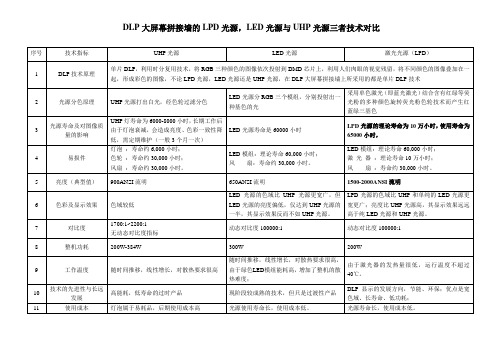
对比度
1700:1~2200:1
无动态对比度指标
动态对比度100000:1
动态对比度100000:1
8
整机功耗
200W-384W
300W
200W
9
工作温度
随时间推移,线性增长,对散热要求很高
随时间推移,线性增长,对散热要求很高,由于绿色LED模组能耗高,增加了整机的散热难度;
由于激光器的发热量很低,运行温度不超过40℃。
2
光源分色原理
UHP光源打出白光,经色轮过滤分色
LED光源分RGB三个模组,分别投射出一种基色的光
采用单色激光(即蓝光激光)结合含有红绿等荧光粉的多种颜色旋转荧光粉色轮技术而产生红蓝绿三基色
3
光源寿命及对图像质量的影响
UHP灯寿命为6000-8000小时,长期工作后由于灯泡衰减,会造成亮度、色彩一致性降低,需定期维护(一般3个月一次)
10
技术的先进性与长远发展
高能耗,低寿命的过时产品
现阶段较成熟的技术,但只是过渡性产品
DLP显示的发展方向,节能、环保;优点是宽色域、长寿命、低功耗;
11
使用成本
灯泡属于易耗品,后期使用成本高
光源使用寿命长,使用成本低。
光源寿命长,使用成本低。
DLP大屏幕拼接墙的LPD光源,LED光源与UHP光源三者技术对比
序号
技术指标
UHP光源
LED光源
激光光源(LPD)
1
DLP技术原理
单片DLP,利用时分复用技术,将RGB三种颜色的图像依次投射到DMD芯片上,利用人们肉眼的视觉残留,将不同颜色的图像叠加在一起,形成彩色的图像,不论LPD光源,LED光源还是UHP光源,在DLP大屏幕拼接墙上所采用的都是单片DLP技术
激光指向仪的参数为您奉上 激光指向仪如何操作

激光指向仪的参数为您奉上激光指向仪如何操作激光指向仪接受交直流24~260伏输入、直流3伏输出的具有软启动功能的电源模块给激光模组供电,由激光模组产生的635nm 的红色、532nm的绿色、405nm的蓝色三种激光光源,经过由目镜组、物镜组构成的光学镜筒进行放大和聚焦,在1500米处形成直径50毫米的激光斑点,这就是激光指向仪。
激光指向仪的参数:供电电压: 3.2V工作时间:充分电可连续工作160小时。
充电时间:约5小时(快充)激光管功率:5mW(进口635nm低功耗型)有效射程: 1000m斑点直径: 200米处5mm; 400米处15mm; 600米处20mm;800米处30mm; 1000米处40mm。
纵横向粗调:360°任意纵横向微调:≤±4°尺寸:265×95×120mm重量:1.8Kg(不含电池重量)适用环境大气压:86~110Kpa 环境温度:—20~+40℃ 空气湿度:≤95%激光指向仪接受低功耗半导体激光器发出激光,通过光学系统会聚,使其成为高度准直的激光束,通过水平和垂直微调,完成指向工作。
激光指向仪的原理如何?激光指向仪接受低功耗半导体激光器发出激光,通过光学系统会聚,使其成为高度准直的激光束,通过水平和垂直微调,完成指向工作。
以1500米激光指向仪为例,它接受交直流24~260伏输入、直流3伏输出的具有软启动功能的电源模块给激光模组供电,由激光模组产生的(635nm红光、532nm绿光、405nm蓝光)激光光源;经过由目镜组、物镜组构成的光学镜筒进行放大和聚焦,在1500米处形成直径50毫米的斑点,这就是1500米激光指向仪。
该激光指向仪随着射程小于1500米,光斑也随着渐渐变小,在500米处光斑达到15毫米,1000米处达到40毫米;由于射程由远到近,激光穿透空气介质本领渐渐加强,亮度得到提高;光斑也变得更加稳定,当射程在0~1000处时间斑稳定无漂移。
激光投影仪参数

专业工程机系列投影机产品功能介绍V2.5(PF600/PX700)产品简介:SEEMILE专业工程机系列搭载具有可靠性的新型DLP光学引擎,释放出5000-7000流明的高亮度,以及15000:1的高对比度,具备1920*1080高清分辨率,可以广泛应用如数字高清影院,大型展示厅、个人专属电影院以及大屏幕拼接等,同时也使用于在明亮的场所做数字广告展示、大型体育场馆显示、城市形象工程建设等等。
它可以从不同的信号源,通过个人电脑,摄像机,蓝光播放器等设备,播放清晰、锐利的影像画面的同时,凭借其高亮度的输出,展现亮丽清晰的影像,可以让体验者在享受视觉效果的震撼。
不仅如此,通过PC实现对投影机的完全控制,方便灵活应用于大屏幕拼接演示,可以展示更多的画面应用。
功能特点:15000-6000流明色彩亮度,满足多种场合;2单芯片激光DLP™投影机高清图像3实现在建议使用寿命 20,000 小时内始终保持相同的亮度。
4动态对比度15000:15基础、进阶两种菜单设置模式;6720°全方位自由安装7数字垂直梯形修正功能,轻松获得理想的对称画面8多款镜头可换,适应复杂的安装条件(0.34/0.54/0.7-1.2/0.8/1.07-1.7) 9全密闭光引擎,确保高效防尘10内置色彩校正,确保画面一致性11控制接口丰富、便于多控制协议,RJ45\RS232\Pj-Link12网页控制功能13支持3D-ready /3D 色彩管理/上下左右格式输入14三重防盗(防盗杆/防盗孔/开机安全密码)15自动信号搜索16镜头中置设计,一键更换镜头17SLPL激光模组技术,双色轮同步高速运作,确保颜色纯正亮丽18支持直接断电保护,支持投影机即开即关;19自动温度控制,实时侦测环境温度,自动调整风扇转速,33db低噪音运行20上下位移+100%大幅度镜头位移调整,支持画面巨幅调整,安装加灵活21REC.709色彩空间大于115%技术规格:尺寸图纸。
Neo 激光器模块手册说明书

注意
• 请阅读、理解并遵守注意事项和操作说明。了解与使 用任何电刺激、激光设备或超声波设备相关的限制和 危险。遵守设备上提供的注意事项和操作标贴说明。
• 设备的设计规格符合电磁安全标准。本设备将产生、 利用并可能发出射频能量,如未遵照说明进行安装和 使用,可能会对附近设备产生有害干扰。但是我们不 保证在特定环境下本系统不会产生干扰。可以通过开 关本设备确定是否对其他设备造成有害干扰。尝试用 以下一种或多种方法消除干扰:
插入线缆 下图显示的是插入线缆的位置
7. 如图所示在底部的左和右侧插入带有连接开口的 面板(随模块一起提供),听到咯嗒声表示顶部 就位。
如需完整的用户操作说明,包括“注意”、“警告”、 “危险”、“适用范围”和“禁忌”,请参阅用户手册。
• 国内市场(仅指美国)请参阅《Vectra Neo 临床治 疗系统用户手册》,货号 13-7646(CD 版本,货号 13-7647)。
警告
• 只有在持证医师或者执业医师持续监督的情况下才 可使用本设备。
• 请确保本设备在电气接地时,只连接符合适用的国 家和地方电气法规的接地插座。
• 应将本设备置于儿童触及范围之外。 • 使用非本用户手册中指定的附件可能会增加电气放
射,降低设备的电气抗扰性。 • 在使用故意以未屏蔽方式辐射电磁能的其他设备的
Neo 激光器模块手册
激光器规格
电源
电气类型 . . . . . . . . . . . . . . . . . . . . . . . . . . . . . . . . . . . . . . . . . . . . . . . . . . . B 型 输出类型 . . . . . . . . . . . . . . . . . . . . . . . . . . . . . . . . 红外线灯(激光) 激光等级 . . . . . . . . . . . . . . . . . . . . . . . . . . . . . . . . . . . . . . . . . . . . . . . . . . . . . 3B 激光器技术规格
多模式光谱稳定激光模块说明书

Multimode Spectrum Stabilized Laser Module Series − Lab VersionsInstallation and Operation Manual Document Number LASER-785-LAB-02-0409Office: 830 Douglas Ave., Dunedin, FL, USA 34698 Phone 727.733.2447 Fax 727.733.3962 8 a.m.– 8 p.m. (Mon-Thu), 8 a.m.– 6 p.m. (Fri) EST E-mail:********************(General sales inquiries) **********************(Questions about orders) ***************************(Technical support)WARNING Protective Eye Wear Should Be Worn When Using This Instrument - Intense Radiation Present See Important Safety Notices inside.AdditionalOffices: 666 Gubei Road, Kirin Tower, Suite 601B, Changning District,Shanghai, PRC. 200336Phone 86.21.5206.8686Fax 86.21.5206.8686******************************Sales and Support CenterGeograaf 24, 6921 EW DUIVEN, The NetherlandsPhone 31-26-3190500Fax 31-26-3190505E-Mail **********************Regional HeadquartersMaybachstrasse 1173760 OstfildernPhone 49-711 34 16 96-0Fax 49-711 34 16 96-85E-Mail ******************Copyright © 2009 Ocean Optics, Inc.All rights reserved. No part of this publication may be reproduced, stored in a retrieval system, or transmitted, by any means, electronic, mechanical, photocopying, recording, or otherwise, without written permission from Ocean Optics, Inc.This manual is sold as part of an order and subject to the condition that it shall not, by way of trade or otherwise, be lent, re-sold, hired out or otherwise circulated without the prior consent of Ocean Optics, Inc. in any form of binding or cover other than that in which it is published. TrademarksMicrosoft, Windows, Windows 95, Windows 98, Windows Me, Windows NT, Windows 2000, Windows XP and Excel are either registered trademarks or trademarks of Microsoft Corporation.Limit of LiabilityEvery effort has been made to make this manual as complete and as accurate as possible, but no warranty or fitness is implied. The information provided is on an “as is” basis. Ocean Optics, Inc. shall have neither liability nor responsibility to any person or entity with respect to any loss or damages arising from the information contained in this manual.Important Safety Notices The Class IIIB laser described here produces a laser emission of 785 nm with output power levels exceeding 350 mW. All models except the –S are designed to be used in a fiber-coupled configuration (-S is designed for SMA coupling); any other configuration may expose the user to hazardous radiation.This laser is safe to operate, provided the user pays attention to all safety warnings:1.Post warnings in the area of the laser beam to alert those present.2.Keep all unauthorized personnel out of the area where the laser is operated to avoid potentiallyhazardous exposure to eyes and skin.3.Whenever the laser is running and the beam is not in use, it is good operating practice tomechanically block the path.4.Never look directly into the laser source or scattering laser light from any reflective surface.Never sight down the beam into the source.5.Maintain experimental setup at low heights to prevent inadvertent beam-eye contact.6.As a precaution against accidental exposures to the output beam or its reflection, operators shouldwear laser safety glasses attenuated to the wavelength being generated.Important Safety NoticesSources for additional information and assistance on laser safety are the following: Center for Device and Radiological HealthOffice of Compliance2098 Gaither Rd.Rockville, MD 20850Tel: 301 594 4654Fax: 301 594 4672Laser Institute of America12424 Research Parkway, Suite 125Orlando, FL 32826Tel: 407 380 1553Fax: 407 380 5588Table of Contents About This Manual (iii)Document Purpose and Intended Audience (iii)Document Summary (iii)Product-Related Documentation (iii)Upgrades (iii)Chapter 1: Introduction (1)Overview (1)Lab Version Models (2)Features (2)Package Contents (3)Additional Equipment Required (3)Chapter 2: Set-up and Operation (5)Overview (5)Set-up (5)Set-up for Operation in Internal Power Preset Mode (6)Set-up for Operation to Control Power Through the Front Panel (7)Set-up for Operation in External Power Control Mode (8)Operation (8)Operation in Internal Power Preset Mode (8)Operation Controlling Power Through the Front Panel (9)Operation in External Power Control Mode (10)Using the Remote Interlock Feature (10)Shutting Down the Laser (11)Index (13)Table of ContentsAbout This ManualDocument Purpose and Intended AudienceThis document provides you with information to get your laser set up and operating. Document SummaryChapter DescriptionChapter 1: Introduction Contains a list of product features and packagecontents.Chapter 2: Set-up and Operation Provides instructions for setting up and operating thelaser.Product-Related Documentation•Multimode Spectrum Stabilized Laser Subsystem Installation and Operation ManualYou can access documentation for Ocean Optics products by visiting our website at. Select Technical → Operating Instructions, then choose the appropriate document from the available drop-down lists. Or, use the Search by Model Number field at the bottom of the web page.You can also access operating instructions for Ocean Optics products on the Software and Technical Resources CD included with the system.Engineering-level documentation is located on our website at Technical → Engineering Docs. UpgradesOccasionally, you may find that you need Ocean Optics to make a change or an upgrade to your system. To facilitate these changes, you must first contact Customer Support and obtain a Return Merchandise Authorization (RMA) number. Please contact Ocean Optics for specific instructions when returning a product.About This ManualChapter 1IntroductionOverviewThe Multimode Spectrum Stabilized Laser Subsystem Series – Lab Versions consists of three models of continuous wave lasers designed specifically for Raman spectroscopy (see Lab Version Models). These laser models feature an internal 350 mW spectrum stabilized laser module that contains an integral Thermo-Electric Cooler (TEC) and thermistor for monitoring the internal temperature of the laser platform. The laser has narrow spectral lines, is compact and features a hermetically sealed laser component, making it optimal for industrial and medical applications.The unit comes complete with a laser-enable switch for safety, a safety key lockout, and an emergency shut-off switch.Multimode Spectrum Stabilized Laser Subsystem1: IntroductionSpectral Output Captured with HR4000 SpectrometerLab Version ModelsThis document covers the installation and operation of the following laser models:•LASER-785-IP-LAB − 785 nm spectrum stabilized multi-mode laser with > 350mW of fiber-coupled output power•LASER-785-LAB-ADJ − 785 nm spectrum stabilized multi-mode laser with > 350mW of fiber-coupled, adjustable output power. Also features an LED display and an output power control dial.•LASER-785-IP-ADJ-S − 785 nm spectrum stabilized multi-mode laser with > 350mW of SMA-coupled, adjustable output power. Also features an LED display and an output power control dial. In addition, the LASER-785-IP-OEM laser is available. This is a single-mode laser with >350mW of fiber-coupled output power. This version is documented in the Multimode Spectrum Stabilized Laser Subsystem Installation and Operation Manual. See Product-Related Documentation for more information.FeaturesThe laser provides the following features:•>350 mW Fiber Coupled or SMA-coupled (-S model) Output Power•Narrow Spectral Line width of only 0.2 nm•Thermo-Electric Cooler (TEC)•Low Power consumption (< 5.5 W)1: Introduction •Remote Interlock, Safety Key Lock-out and Emergency shut-off•LED display for output power setting (Models LASER-785-LAB-ADJ and LASER-785-LAB-ADJ-S only)•Output power control dial (Models LASER-785-LAB-ADJ and LASER-785-LAB-ADJ-S only) Package ContentsOne (1) Ocean Optics Multimode Stabilized LaserOne (1) ThermistorOne (1) power cordTwo (2) Master Power keysOne (1) remote plugAdditional Equipment RequiredThe following equipment, available from Ocean Optics, is also required to use your laser: Safety goggles (R-2001-GL goggles from Ocean Optics are recommended)1: IntroductionChapter 2Set-up and OperationOverviewThis section provides instructions for setting up and operating the laser. Read all instructions and warnings carefully before attempting to install and operate your laser.Set-upThe laser set-up procedure differs, depending on whether you are going to control the output power automatically via the Internal Preset mode (Model LASER-785-IP-LAB), manually through the unit’s front panel (Models LASER-785-LAB-ADJ and LASER-785-LAB-ADJ-S), or remotely (all models).Laser Rear Panel View2: Set-up and OperationSet-up for Operation in Internal Power Preset ModeUse these set-up instructions for the Internal Power Preset mode (Model LASER-785-IP-LAB).►Procedure1.Make sure that the master Power key is in the vertical (“Off’) position.2.Connect the 120V AC power plug to the power connector on the rear of the unit.3.Plug the other end of the power cord into a standard 110/120V electrical outlet.4.Connect a FC/PC Multi-mode fiber patch cord to the FC/PC bulkhead connector on the frontpanel of the unit.5.Note that this laser is configured with a remote interlock on the rear panel. The laser has an RJ-11(4-pin telephone jack) that is prewired to provide a closed loop connection for the interlock.Removal of the RJ-11 connector or a break in the closed loop circuit provided will result in alaser interrupt and the system will be reset to standby mode. You can reconfigure the RJ-11connector to provide a closed loop that interactively couples with their system or facility byreplacing the short length of wire with longer closed loop connections, if desired.6.Ensure that the Emergency Shut-off switch (EMO) is in the “ready” position by turning the redbutton clockwise until it pops out slightly.7.You are now ready to turn on the laser module. Go to Operation in Internal Power Preset Mode.2: Set-up and Operation Set-up for Operation to Control Power Through the Front PanelUse these set-up instructions when you want to control the laser power through the unit’s front panel (Models LASER-785-LAB-ADJ and LASER-785-LAB-ADJ-S).►Procedure1.Make sure that the master Power key is in the vertical (“Off’) position.2.Connect the 120V AC power plug to the power connector on the rear of the unit.3.Plug the other end of the power cord into a standard 110/120V electrical outlet.4.Connect an SMA 905 connectorized multi-mode fiber patch cord to the SMA bulkhead connectoron the front panel of the unit.5.Note that this laser is configured with a remote interlock on the rear panel. The laser has an RJ-11(4-pin telephone jack) that is prewired to provide a closed loop connection for the interlock.Removal of the RJ-11 connector or a break in the closed loop circuit provided will result in alaser interrupt and the system will be reset to Standby mode. You can reconfigure the RJ-11connector to provide a closed loop that interactively couples with their system or facility byreplacing the short length of wire with longer closed loop connections, if desired.6.Ensure that the Emergency Shut-off switch (EMO) is in the “ready” position by turning the redbutton clockwise until it pops out slightly.7.You are now ready to turn on the laser module. Go to Operation Controlling Power Through theFront Panel.2: Set-up and OperationSet-up for Operation in External Power Control ModeThe Model LASER-785-IP-LAB laser is designed for operation in the Internal Power Preset mode and the Models LASER-785-LAB-ADJ and LASER-785-LAB-ADJ-S are designed for operation through their front panel controls. However, the laser provides you with the capability (via an external port on the back panel) of adjusting the power remotely via computer or signal generator in External Power Control mode. Use these set-up instructions for the External Power Control mode. See for Operation in External Power Control Mode operation instructions in this mode.►Procedure1.Make sure that the laser power is not operating by pressing the Laser On switch and assuring thatthe Laser On LED on the front panel is not lit.2.Set the Mode Selection switch on the rear panel to External (the amber Operating Mode LEDwill light).3.Connect a BNC cable to the Control port on the rear panel.4.Go to Operation in External Power Control Mode to operate the laser in External Power Controlmode.OperationRead the following warning before attempting to use the laser:WARNINGSDO NOT LOOK DIRECTLY INTO THE LASER. LASER RADIATION ISHAZARDOUS TO THE EYES.AVOID DIRECT EXPOSURE TO THE BEAM.Operation in Internal Power Preset ModeUse this procedure to operate the Model LASER-785-IP-LAB laser in the Internal Power Preset mode.►Procedure1.Turn the master Power key (on the rear panel) 90 degrees clockwise to the horizontal “ON”position. The green System Power LED (on the front panel) lights indicating that system power is on.2: Set-up and Operation2.Push the Laser On switch (on the front panel). The red LED on the front panel lights to indicatethat the laser is in operation. The laser turns on approximately 2 seconds after the switch ispressed.NoteNote that the switch returns to the center position after you press it. At this point, it canfunction as a manual reset.3.In the event of a power interruption, power failure or interlock break, the laser is automaticallydisabled. To re-enable it, toggle the Laser On switch to back to the ON position. Operation Controlling Power Through the Front PanelUse this procedure to control the laser power through the unit’s front panel (Models LASER-785-LAB-ADJ and LASER-785-LAB-ADJ-S).►Procedure1.Turn the master Power key (on the rear panel) 90 degrees clockwise to the horizontal “ON”position. The green System Power LED (on the front panel) lights indicating that system power is on.2.Turn the laser adjustment dial on the front panel to the desired drive current setting. The setting isdisplayed on the front panel LED.3.Push the Laser On switch (on the front panel). The red LED on the front panel lights to indicatethat the laser is in operation. The laser turns on approximately 2 seconds after the switch ispressed.2: Set-up and OperationNoteNote that the switch returns to the center position after you press it. At this point, it canfunction as a manual reset.4.In the event of a power interruption, power failure or interlock break, the laser is automaticallydisabled. To re-enable it, toggle the Laser On switch to back to the ON position.Operation in External Power Control ModeThe Multimode Spectrum Stabilized Laser provides the capability of adjusting the power remotely via computer or signal generator in External Power Control mode. Use the following procedure: ►Procedure1.Make sure that a BNC cable is connected to the Control port on the rear panel as described in Set-up for Operation in External Power Control Mode.2.Apply a DC bias between 0 (zero power) and 1 (full power) Volt to modulate the laser or toadjust the laser’s output power. The unit can be modulated at rates up to approximately 300 KHz.3.Push the Laser On switch (on the front panel). The laser then outputs a variable amount if outputpower dependent on the DC bias voltage that has been applied to the Control port on the rearpanel.Using the Remote Interlock FeatureThe Remote Interlock is a safety feature that automatically shuts down the laser when a trigger such as a door or an enclosure opening occurs. You may decide to enable a remote interlock mechanism when integrating the laser into a laboratory or system environment.The interlock is located on the rear panel and uses an RJ-11 plug. The Remote Interlock is normally an open circuit, so the provided RJ-11 connector or a user-configured closed loop interconnect MUST be in place for proper function of the laser module. To enable the Remote Interlock, you must obtain an RJ-11 plug (or modify the plug provided) and create a closed circuit between the two signal terminals of the plug and insert the closed-circuit RJ-11 plug into the Interlock jack.The laser functions normally when is senses a closed circuit, but it will disable laser output when it detects an open circuit. To re-enable the laser function, you must make sure that the interlock is a closed circuit, and then manually reset the laser by toggling the Laser On switch on the front panel to the ON position.2: Set-up and Operation Shutting Down the LaserUse the following procedure when you are finished using the laser and need to shut it down.►Procedure1.Push the Laser On toggle switch (on the front panel) to turn the laser off. Make sure that theLaser On LED goes off.2.Turn the master Power key (on the rear panel) 90 degrees to the vertical “off” position. The greenSystem Power LED (on the front panel) goes off indicating that system power is off.3.Disconnect the fiber or SMA cords and power cable as needed.2: Set-up and OperationIndexCControl Power Through Front Panel set-up, 7Controlling Power Through the Front Panel operation, 9Ddocumentaudience, iiipurpose, iiisummary, iiiEequipmentrequired, 3External PowCOntrol modeoperation, 10External Power Control modeset-up, 8Ffeatures, 2IInternal Power Preset modeoperation, 8set-up, 6introduction, 1Mmanual operationset-up, 6, 7, 9models, 2Ooperation, 8Controlling Power Through the Front Panel, 9 Extarnal Power Control mode, 10Internal Power Preset mode, 8Ppackage contents, 3product-related documentation, iiiRrear panel, 5Remote Interlock, 10remote operationset-up, 8required equipment, 3Sset-up, 5Control Power Through Front Panel, 7External Power Control mode, 8Internal Power Preset mode, 6manual operation, 6, 7, 9remote operation, 8shut down, 11spectral output, 2Uupgrades, iiiIndex。
杨成东 报告

掺镨离子激光器最近国内外研究进展
国内研究 2013年,厦门大学课题组,Z. Liu等人使用GaN作为泵浦源 ,对Pr:YLF泵浦获得了 698nm的深红光激光输出,功率为 156mW。
2011长春理工大学通过倍频Nd:GSAG获得471nm 2.8的 蓝光,并用于泵浦PrKYsFio,获得了 610nm的激射,功率 为210mW.
Pr3+ :YLF晶体的激光实验
Pr3+ :YLF晶体激光实验
实验需要改进的地方
1.需要增加腔内色散补偿(用棱镜或色散镜)以及饱 和吸收透镜的非线性参数。
2.磷化镓铟饱和吸收透镜在更短点的波长时也可以高 反。( Pr:YLF激发的波长在620nm附近)
基于Pr:YLF的橙光应用——白光激光样机
Pr可见激光
报告人:杨成东
深圳大学光电工程学院 2015年4月11日
1
研究背景
全固态激光器因其小型化、高效率、长寿命和稳定性 好等优点,成为近年来激光领域研究的热点。 目前应用最多的固体激光器有钕激光器、铒激光器、 铥激光器等发出的光都集中在非可见光波。 研究能够直接产生可见光激光的新型工作介质对于科 学研究以及实践应用都具有十分重要的意义。
常见的掺镨晶体
1 Pr3+与氟化物结合 Pr:LLF Pr:KYF Pr:YLF
常见的掺镨晶体
2.镨离子还可以与别的稀土元素离子一起共掺。 如采用稀土离子Pr3+与Ce3+共掺在YAG基质,通过 出射610nm来增加荧光粉中的红光成分 3.镨离子与氧化物结合 如Pr3+ :CaW04
YLF晶体的离子激光器最近国内外研究进展
国外研究 2013年,法国卡昂大学在Pr:YLF波导实现了输出功率为 12mW的604.2nm与功率为25mW的639.5nm的激射,斜 效率分别为6%和5%。 2011德国汉堡大学Huber课题组采用两个443.9nm波 长的蓝光LD泵浦长为2.9mm、掺杂浓度为0.5a.t.%的 Pr:YLF晶体,做出的结果是 522.6nm (773mW、61.5%). 607.2nm (418mW、32%)
激光模组的工作原理

激光模组的工作原理
当激光二极管通电时,电流通过二极管,使得电子和空穴在半导体中复合,产生光子。
这些光子在反射镜的反射下,在腔体内来回反射,形成激光。
透镜的作用是将激光束聚焦,使其能够更好地穿透和聚焦于目标物体上。
驱动电路主要控制激光模组的电流和电压,调整激光的功率和频率。
同时,为了保证激光模组的长期稳定性,还需要进行温度和湿度等环境参数的控制和保护。
总之,激光模组的工作原理主要是通过激光二极管产生激光,通过透镜聚焦激光束,再通过驱动电路控制激光的功率和频率,从而实现激光束的输出。
- 1 -。
《GaN基蓝光激光二极管外延结构设计及其光电性能研究》范文

《GaN基蓝光激光二极管外延结构设计及其光电性能研究》篇一摘要:本文针对GaN基蓝光激光二极管(Blue Laser Diode,BLD)的外延结构设计及光电性能进行研究。
通过对外延结构的详细设计和优化,旨在提升蓝光激光二极管的光电转换效率和激光输出功率。
本文首先介绍了GaN材料的基本性质和蓝光激光二极管的发展背景,然后详细阐述了外延结构的设计原理和实验方法,最后通过实验数据和结果分析,验证了所设计外延结构的有效性,并对其光电性能进行了深入研究。
一、引言随着信息技术的快速发展,蓝光激光二极管(BLD)因其高亮度、高分辨率和长寿命等优点,在光存储、光通信和显示技术等领域得到了广泛应用。
GaN基蓝光激光二极管是其中的关键器件,其性能主要取决于外延结构的设计和优化。
因此,对GaN基蓝光激光二极管的外延结构设计及其光电性能的研究具有重要意义。
二、GaN材料的基本性质GaN(氮化镓)是一种重要的半导体材料,具有宽带隙、高电子迁移率和高热导率等特性,是制造蓝光激光二极管的理想材料。
然而,GaN材料的生长过程复杂,对外延结构的设计和制备工艺要求较高。
三、外延结构设计原理与实验方法1. 设计原理:本研究首先确定了外延结构的基本组成,包括缓冲层、n型GaN层、量子阱活性层以及p型GaN层等。
针对蓝光激光二极管的特殊要求,对外延结构进行了优化设计,旨在提高载流子浓度、降低阈值电流和提高光束质量。
2. 实验方法:采用金属有机化学气相沉积(MOCVD)技术制备外延结构。
通过调整生长温度、气体流量和掺杂浓度等参数,实现了对GaN基材料的高质量生长。
四、实验结果与分析1. 形貌与结构分析:通过原子力显微镜(AFM)和X射线衍射(XRD)等手段,对外延结构的表面形貌和晶体结构进行了分析。
结果表明,优化后的外延结构表面平整度提高,晶体质量得到显著改善。
2. 光电性能测试:对制备的蓝光激光二极管进行了光电性能测试,包括阈值电流、输出功率、光束质量和寿命等。
高转换效率腔内倍频外腔面发射蓝光激光器

高转换效率腔内倍频外腔面发射蓝光激光器
伍亚东;朱仁江;晏日;彭雪芳;王涛;蒋丽丹;佟存柱;宋晏蓉;张鹏
【期刊名称】《物理学报》
【年(卷),期】2024(73)1
【摘要】高功率高光束质量的蓝色激光在激光显示与照明、水下通信和成像、有色金属加工等许多领域具有广泛应用前景.本文利用增益芯片底部的高反镜分布布拉格反射镜、折叠镜以及后端反射镜构成V型谐振腔,通过腔内插入非线性晶体LBO,获得了高转换效率的高功率、高光束质量蓝光输出.实验研究了非线性晶体的长度、基频激光的线宽、倍频走离角的补偿等不同因素对外腔面发射激光器腔内倍频蓝光输出功率的影响.在LBO的Ⅰ类相位匹配条件下,当晶体长度为5 mm,所用双折射滤波片厚度为1 mm时,获得超过6 W的491 nm波长蓝光输出,x和y方向的光束质量M2因子均为1.08,倍频转换效率为63%.
【总页数】7页(P174-180)
【作者】伍亚东;朱仁江;晏日;彭雪芳;王涛;蒋丽丹;佟存柱;宋晏蓉;张鹏
【作者单位】重庆师范大学物理与电子工程学院;中国科学院长春光学精密机械与物理研究所;北京工业大学理学部;重庆师范大学重庆国家应用数学中心
【正文语种】中文
【中图分类】TN2
【相关文献】
1.光泵浦半导体垂直外腔面发射激光器的倍频研究
2.小型高效率腔内倍频473nm 蓝光激光器
3.高功率转换效率905nm垂直腔面发射激光器的设计与制备
4.LD泵浦腔内倍频高功率蓝光激光器
5.LD泵浦腔外倍频高转换效率Nd^(3+)∶GdVO_4固体激光器
因版权原因,仅展示原文概要,查看原文内容请购买。
基于合束的500w蓝光半导体激光模块化研究

《基于合束的500w蓝光半导体激光模块化研究》一、前言近年来,随着科技的不断进步,蓝光半导体激光技术正日益成为研究和应用领域的热点。
在这一领域中,基于合束的500w蓝光半导体激光模块化研究备受关注,其在材料加工、医疗设备、激光显示等领域具有广泛的应用前景。
本文将就这一主题展开深入探讨。
二、500w蓝光半导体激光模块化的概念解析1. 蓝光半导体激光技术500w蓝光半导体激光技术是指利用半导体材料来产生蓝色光束的技术。
相比于常见的激光技术,蓝光激光具有更短的波长和更高的能量密度,因此在一些特定的应用领域具有比较明显的优势。
2. 合束技术合束技术是指将多束激光束通过某种方式叠加成一束激光束的技术。
在500w蓝光半导体激光模块化中,合束技术可以有效提升输出功率和光束质量,保证光束在传输过程中的稳定性和一致性。
三、500w蓝光半导体激光模块化的研究进展1. 技术原理500w蓝光半导体激光模块化主要依靠高功率半导体激光器和优化的合束技术。
通过半导体激光器产生高功率的蓝光激光,然后利用合束技术将多束激光束合成一束,从而实现500w蓝光半导体激光的模块化输出。
2. 关键技术挑战在500w蓝光半导体激光模块化研究中,面临着一些关键技术挑战。
如何提高半导体激光器的功率密度、如何有效地进行激光束合束、如何降低模块化过程中的能量损耗等都是亟待解决的问题。
3. 应用展望500w蓝光半导体激光模块化技术在材料加工、医疗设备、激光显示等领域具有广泛的应用前景。
在材料加工领域,该技术可以提高加工效率和加工质量;在医疗设备领域,可以应用于激光手术和激光治疗等方面;在激光显示领域,可以实现更高分辨率和更鲜艳的颜色表现。
四、个人观点与总结通过对基于合束的500w蓝光半导体激光模块化研究的分析,我认为这一技术将在未来的各个领域有广泛的应用前景。
在科技不断发展的今天,我们要不断探索和突破技术瓶颈,为人类社会的进步贡献自己的力量。
基于合束的500w蓝光半导体激光模块化研究是一个具有重要意义的课题,它不仅代表着激光技术的发展方向,更为各个行业的发展带来了新的机遇和挑战。
激光模组的工作原理

激光模组的工作原理
激光模组是一种利用激光技术进行数据传输、测量和处理的组件。
其工作原理主要分为两个部分:激光发射和激光接收。
在激光发射方面,激光器会产生一束高度聚焦的激光束,并通过光纤或其他光学传输介质将其传输到目标位置。
在激光接收方面,激光束被传输到相应的探测器上,利用探测器将激光信号转换成电信号,进行信号处理和解调,最终实现数据传输或测量处理的功能。
激光模组的工作原理具有高速、高精度、高稳定性的特点,广泛应用于通信、自动化、医学、军事等领域。
- 1 -。
高亮度白色激光光源提升远光性能的研究

高亮度白色激光光源提升远光性能的研究杨志;庞宏力;靳冠洋;陈思远【摘要】激光照明技术具有高亮度、光效高等特性,是下一代固态照明的理想光源.通过高功率的半导体蓝色激光泵浦激发含Ce∶ YAG (Y3AL5O12∶Ce3+)荧光粉的光色转换材料去获取高亮度白色激光光源.但是入射的高功率激光是直接聚焦在光色转换材料上的,对其耐热性、适用高能量密度光激发等特性提出了较高的要求.本文采用丝网印刷法、真空烧结在蓝宝石衬底上制备了高性能的Ce:YAG荧光陶瓷涂层,并和商业蓝色激光二极管进行了器件封装,获得了142 lm/W的光效.最后在整车上集成了开发的激光辅助远光功能模块的激光大灯,实验结果表明,高亮度的白色激光光源可提升夜间远光的可视距离至600 m,极大的提升了夜间驾驶安全性.【期刊名称】《照明工程学报》【年(卷),期】2018(029)005【总页数】7页(P78-84)【关键词】激光照明;Ce∶YAG;荧光陶瓷涂层;激光大灯;白色激光光源【作者】杨志;庞宏力;靳冠洋;陈思远【作者单位】曼德电子电器有限公司光电分公司,河北保定071000;曼德电子电器有限公司光电分公司,河北保定071000;曼德电子电器有限公司光电分公司,河北保定071000;曼德电子电器有限公司光电分公司,河北保定071000【正文语种】中文【中图分类】U463.65引言随着汽车工业的快速发展以及逐年增长的交通事故率,人们对汽车的安全性提出了越来越高的要求。
汽车灯具作为汽车的主动安全部件,近十年来随着固态照明技术的发展和车灯新技术的应用,使得夜间行车的安全性得到很大的提升。
远光作为前照灯一个重要的基础照明功能,能在夜间提供较远距离的照明范围,使驾驶员能够提前发现障碍物。
而影响远光灯照明距离的核心因素是光源,具体是指光源的亮度特性。
而激光具有的高亮度特性正是获得高亮度白光的理想光源。
激光照明的核心技术是LARP (Laser Activated Remote Phosphor)激光远程激发荧光技术,具体是将高功率的激光束泵浦激发含Ce:YAG荧光粉的光色转换材料,透射的蓝色激光和激发产生的黄光黄色荧光通过混色原理,产生人眼感知的高亮度白光光源[1]。
2024年RGB激光模块市场发展现状
RGB激光模块市场发展现状引言RGB(红、绿、蓝)激光模块是一种新兴的激光技术,它能够同时发射红、绿和蓝光,具有更广泛的颜色选择和更高的亮度。
RGB激光模块在多个应用领域中表现出巨大的潜力,如显示技术、照明、传感器、医疗设备等。
本文将探讨RGB激光模块市场的发展现状,并从各个角度进行分析。
市场规模分析根据市场调查数据显示,RGB激光模块市场在过去几年中呈现出强劲的增长态势。
这主要得益于RGB激光模块在各个行业中广泛应用的趋势。
同时,不断推出的新型RGB激光模块产品和技术创新也进一步推动了市场的发展。
根据预测,RGB激光模块市场的总体规模将在未来几年中持续增长。
应用领域分析显示技术RGB激光模块在显示技术领域有着广泛的应用,尤其在投影仪市场上表现出色。
传统的投影仪使用单一光源,而RGB激光模块能够提供更高亮度和更丰富的颜色选择,使得投影效果更加清晰和真实。
随着投影仪市场的不断发展,RGB激光模块的需求也在不断增加。
照明RGB激光模块在照明领域也显示出巨大的潜力。
相比传统的白光照明,RGB激光模块可以通过控制红、绿、蓝光的混合比例来实现更多样化的照明效果。
此外,RGB 激光模块具有更长的寿命和更低的能耗,使其在室内和室外照明应用中受到越来越多的关注。
传感器RGB激光模块在传感器领域的应用也日益增多。
RGB激光模块能够发射不同波长的光线,可以用于距离测量、三维成像等应用。
特别是在自动驾驶和机器人领域,RGB激光模块被广泛应用于环境感知和障碍物检测。
医疗设备在医疗设备领域,RGB激光模块也发挥着重要作用。
例如,激光治疗设备和激光手术器械通常需要使用RGB激光模块来提供所需的光线。
此外,RGB激光模块还被应用于眼科和皮肤治疗等领域,为医疗设备的发展做出了贡献。
技术挑战与发展趋势虽然RGB激光模块市场发展迅速,但也面临一些技术挑战。
首先是成本问题,目前RGB激光模块的价格相对较高,限制了其在某些应用领域的普及。
半导体激光器模组评价标准

半导体激光器模组评价标准1.波长精度波长精度是衡量半导体激光器模组性能的重要指标之一。
波长精度越低,说明模组的波长稳定性越好。
在评价波长精度时,应考虑以下因素:⏹中心波长偏差:模组的实际中心波长与标称中心波长的偏差;⏹波长漂移:在长时间工作或温度变化时,模组的波长稳定性;⏹温度对波长的影响:不同温度下,模组的波长变化情况。
1.发射功率发射功率是指半导体激光器模组输出的光功率。
在评价发射功率时,应考虑以下因素:⏹最大输出功率:模组的最大输出光功率;⏹功率稳定性:在一定温度范围内,模组的功率稳定性;⏹温度对功率的影响:不同温度下,模组的功率变化情况。
1.光束质量光束质量是衡量半导体激光器模组光束质量的重要指标。
在评价光束质量时,应考虑以下因素:⏹光束发散角:模组的发散角大小;⏹光束质量因子(M²):描述光束质量与理想情况下的差距程度;⏹光束横截面形状:模组的横截面形状,如圆形、椭圆形等。
1.频率稳定性频率稳定性是指半导体激光器模组输出光的频率稳定性。
在评价频率稳定性时,应考虑以下因素:⏹频率漂移:在长时间工作或温度变化时,模组的频率稳定性;⏹温度对频率的影响:不同温度下,模组的频率变化情况。
1.噪声性能噪声性能是指半导体激光器模组输出的光噪声性能。
在评价噪声性能时,应考虑以下因素:⏹噪声类型:模组的噪声类型,如散粒噪声、热噪声等;⏹噪声水平:模组的噪声水平,如光强波动等;⏹噪声对系统的影响:噪声对系统性能的影响程度。
1.温度稳定性温度稳定性是指半导体激光器模组在温度变化时,性能的稳定程度。
在评价温度稳定性时,应考虑以下因素:⏹温度对波长的影响:不同温度下,模组的波长变化情况;⏹温度对功率的影响:不同温度下,模组的功率变化情况;⏹温度对频率的影响:不同温度下,模组的频率变化情况。
1.可靠性及寿命可靠性及寿命是衡量半导体激光器模组可靠性和使用寿命的重要指标。
在评价可靠性及寿命时,应考虑以下因素:⏹工作寿命:模组的正常工作时间或寿命;⏹环境适应性:模组在不同环境条件下的适应性;⏹故障率:模组在正常工作期间的故障率。
蓝光激光器焊接应用场景

蓝光激光器焊接应用场景近年来,随着科技的不断进步,蓝光激光器焊接技术在工业制造领域得到了广泛的应用。
它以其高能量、高精度和高效率的特点,成为了许多焊接任务的首选工具。
下面将介绍一些蓝光激光器焊接的应用场景。
1.汽车制造在汽车制造领域,蓝光激光器焊接技术被广泛应用于汽车车身的焊接工艺中。
传统的焊接方法,如电弧焊接和激光焊接,往往需要进行多次焊接,从而增加了生产成本和时间。
而蓝光激光器焊接技术,通过高能量的激光束,可以在短时间内完成焊接过程,大大提高了生产效率。
此外,蓝光激光器焊接还可以实现对汽车材料的精确控制,从而提高了焊接质量和产品的可靠性。
2.电子设备制造在电子设备制造领域,蓝光激光器焊接技术被广泛应用于电子元器件的连接工艺中。
传统的焊接方法,如电阻焊接和电弧焊接,往往需要使用焊锡和焊剂,从而增加了产品的成本和污染环境。
而蓝光激光器焊接技术,通过高能量的激光束,可以直接将电子元器件焊接在一起,无需额外的焊接材料。
这不仅降低了产品的成本,还减少了对环境的污染。
3.航空航天制造在航空航天制造领域,蓝光激光器焊接技术被广泛应用于航空发动机的制造工艺中。
航空发动机是飞机最重要的部件之一,对其焊接质量和可靠性要求非常高。
传统的焊接方法,如电阻焊接和电弧焊接,往往无法满足这些要求。
而蓝光激光器焊接技术,通过高能量的激光束,可以实现对航空发动机的高精度焊接,从而提高了产品的质量和可靠性。
4.医疗器械制造在医疗器械制造领域,蓝光激光器焊接技术被广泛应用于医疗器械的组装工艺中。
医疗器械对焊接质量和卫生要求非常高,传统的焊接方法往往无法满足这些要求。
而蓝光激光器焊接技术,通过高能量的激光束,可以实现对医疗器械的无损焊接,从而提高了产品的质量和卫生性。
蓝光激光器焊接技术在汽车制造、电子设备制造、航空航天制造和医疗器械制造等领域都有着广泛的应用。
它以其高能量、高精度和高效率的特点,成为了许多焊接任务的首选工具。
相信随着科技的不断进步,蓝光激光器焊接技术将在更多领域得到应用,为人类的生产和生活带来更多的便利。
矿产
矿产资源开发利用方案编写内容要求及审查大纲
矿产资源开发利用方案编写内容要求及《矿产资源开发利用方案》审查大纲一、概述
㈠矿区位置、隶属关系和企业性质。
如为改扩建矿山, 应说明矿山现状、
特点及存在的主要问题。
㈡编制依据
(1简述项目前期工作进展情况及与有关方面对项目的意向性协议情况。
(2 列出开发利用方案编制所依据的主要基础性资料的名称。
如经储量管理部门认定的矿区地质勘探报告、选矿试验报告、加工利用试验报告、工程地质初评资料、矿区水文资料和供水资料等。
对改、扩建矿山应有生产实际资料, 如矿山总平面现状图、矿床开拓系统图、采场现状图和主要采选设备清单等。
二、矿产品需求现状和预测
㈠该矿产在国内需求情况和市场供应情况
1、矿产品现状及加工利用趋向。
2、国内近、远期的需求量及主要销向预测。
㈡产品价格分析
1、国内矿产品价格现状。
2、矿产品价格稳定性及变化趋势。
三、矿产资源概况
㈠矿区总体概况
1、矿区总体规划情况。
2、矿区矿产资源概况。
3、该设计与矿区总体开发的关系。
㈡该设计项目的资源概况
1、矿床地质及构造特征。
2、矿床开采技术条件及水文地质条件。
- 1、下载文档前请自行甄别文档内容的完整性,平台不提供额外的编辑、内容补充、找答案等附加服务。
- 2、"仅部分预览"的文档,不可在线预览部分如存在完整性等问题,可反馈申请退款(可完整预览的文档不适用该条件!)。
- 3、如文档侵犯您的权益,请联系客服反馈,我们会尽快为您处理(人工客服工作时间:9:00-18:30)。
• 技术参数:
• • • • • • • • • • • • •
光斑形状:点状 一字状 十字状(多种可选) 输出波长:蓝光405nm 型号:RD405-50G3 RB405-50G3 RS405-50G3 光学透镜:玻璃透镜 尺寸:Φ16×70mm(多种可定制) 工作电压:DC2.8-5V(多种可定制) 输出功率:<100mW(多种可定制) 工作温度:-10~50℃ 储存温度:-40~85℃ 使用寿命:连续使用大于8000小时 可选附件:专用电源(AC110-240V转DC3-5V,全球适用) 工业支架(万向调节) 激光等级:IIIb
• 产品特点:
• • • • • (1)温控、驱动和激光器完全集成,结构小巧紧凑,外部只需直流供电 (2)经过高低温存储和振动冲击测试,具有可靠的稳定性,环境温度在15~45度范围时,可24小时连续稳定工作 (3)具有数字调制功能和模拟调制功能 (4)冗余的散热设计、双向温控和完善的双向温度保护功能,可以保证宽 广的工作温度范围而不会影响激光器的寿命。 而且,蓝光一字线激光器整套可广泛应用于各种工业中。同时,在工业和工 艺待业的校正与定位中,取代了标尺、三角板、挡块等设备。并且能够帮助 您在无法采用机械导向或在需要双手同时工作的地方工作。日成可以调节颜 色和亮度,使之适合于材料表面和您所在位置的环境光线。
蓝光激光模组
Blue laser module
主要内容:
日成科技是一家专业从事半导体激光产品研发、设计和生产的高新技 术企业。我公司面向国内外激光、光电子市场,重点针对半导体激光 应用领域,先后开发了点光源、线光源、十字光源、功率可调激光器、 频率可调激光器、光纤藕合激光器等几大类数百种产品,产品广泛应 用于工业指示、医疗、军事、试验教学等领域。 • 蓝光激光模组整套采用半导体激光二极管作为泵浦源,常规类设计 最高输出功率为10瓦。 • 该类激光器采用半导体侧面泵浦,输出功率高,寿命长,便于维护, 内置循环水冷却以保证激光稳定输出,可拨打零贰玖陆捌伍捌壹柒零 玖长间连续工作。• 售后服务
• 对日成科技售出的产品一律保证一年保修,三年维修的原则,在保修期内出 现的任何质量问题将给予认真负责的处理。欢迎用户提供宝贵的改进意见。 gl
