EGN-3-10中文资料
PC 等级
MEP-979G;GS1030;GS-2010MSR-9920A;GS-2020M;
GS-2020MDF;GS-2020MDR-9913A;GS-2020MKR;
GS-2020MLR-Y083;GS-2020MN1;GS-2020MR2;
GSV-2010KR;GSV-2010R2;GSV-2020KR;GSV-2020R2;
GSV-2030KR;GSV-2030R2;GSV-2040KR;GSV-2040R2;
H-3000;H-3000R;H-3000U;H-3000UR;H-3000V;H-4000;
HL-4000;HPR3000;HPR3500;HR3001NR;LCF-2315;LCF-2410;
标准增强性:B-8110R,B-8120R,B-8130R,G-3410R,G-3415R,
G-3420R,G-3430R,G-3110PH,G-3120PH,
低异方性:G-3410H,G-3420H,G-3430H,
等方向性:G-3310M,G-3320M,G-3330M,
增强难然性:B-4110R,B-4120R,B-4130R,BN-8110R,BN-8120R,
TMB1605;TMB1605F;TMB1615;TMB4010;7025G10;7025G15;7025G20;
7025G30;7025G40;7025G20I;GSH2020R2;GS1020;GSH2010MR2;7027R;
GSV2030;GSV2020;GS1040;GS-2025M;GS-2030MKR;GS-2030;GS-2025MR2;
GMB4010;GMB6010;GP-1(ABS+PC);GP-2(ABS+PC);
Inogen One G3 氧浓度器技术手册说明书

INOGEN ONE G3 OXYGEN CONCENTRATORTECHNICAL MANUAL96-03996-00-01Revision FThis Manual applies to the following Inogen, Inc. products: ∙Inogen One G3 Oxygen Concentrator, model # IO-300 ∙Inogen One AC Power supply, model # BA-301∙Battery, model # BA-300∙Battery, model # BA-316TABLE OF CONTENTSRMATION FOR PROVIDERS OF THE INOGEN ONE G3 (4)1.1.C AUTION AND W ARNING S TATEMENTS (4)2.SETTING UP A PATIENT ON INOGEN ONE G3 (6)2.1.R ECOMMENDATIONS FOR U SE (6)2.2.S YSTEM C OMPONENTS (6)2.3.U SING THE I NOGEN O NE G3 (7)2.4.S ELECTING THE P ROPER F LOW S ETTING (7)3.SERVICING THE INOGEN ONE G3 (9)3.1.M AINTENANCE BY THE P ROVIDER (9)3.2.M AINTENANCE BY THE P ATIENT (13)3.3.E XPECTED S ERVICE R EQUIREMENTS (16)4.INOGEN ONE G3 SYSTEM SPECIFICATIONS (16)5.INOGEN ONE G3 ERROR CODE TABLE (18)6.ERROR RECALL (19)7.CONTACTS FOR MORE INFORMATION (19)1. INFORMATION FOR PROVIDERS OF THE INOGEN ONE G3Thank you for choosing to provide your patients with the Inogen One G3 oxygen concentrator. We are pleased to offer you and your patients one solution for your many oxygen needs.This Technical Manual will familiarize you with provider-specific information regarding the Inogen One G3 Oxygen Concentrator and its accessories. Before reading this Technical Manual,please read and review the Inogen One G3 Patient Manual for description and indications for use of the device.Be sure to thoroughly read all of the information in this manual in its entirety. If you have any additional questions, please see the list of contacts at the end of this Technical Manual.Instructions included in this Technical Manual are intended to help assure that patients are given proper guidance in the use and function of the Inogen One G3 and its accessories. Proper One G3, but will also protect the patient, prolong the life of the device, and help you avoid unnecessary service calls and complaints from users.1.1. Caution and Warning StatementsYou will see Warnings and Cautions throughout this Technical Manual. To ensure effective Oxygen Therapy and proper operation of the Inogen One G3 Oxygen Concentrator, you must observe them carefully.In many cases, warnings and cautions have been included in the Inogen One G3 User Manual.2.SETTING UP A PATIENT ON INOGEN ONE G32.1.Indications for UseThe Inogen One G3 Oxygen Concentrator is used on a prescriptive basis by patients requiring supplemental oxygen. It supplies a high concentration of oxygen and is used with a nasal cannula to channel oxygen from the concentrator to the patient. The Inogen One Oxygen Concentrator may be used in a home, institution, vehicle and various mobile environments.2.2.System ComponentsThe following are standard components of the Inogen One system:o Inogen One G3 Oxygen Concentratoro8 Single Battery, BA-300o AC to DC Power Supply, BA-301o DC Power Cordo Carry Bago CannulaPatient Set-Up. To properly set up a patient on the Inogen One G3 System, you may need to provide:o Pulse Oximeter (for titration, not included)o Extra cannulas (not included)ing the Inogen One G3To quickly configure the Inogen One G3 for patient use:1.Slide the battery onto the bottom of the system until the latch clicks into place.2.Connect AC power cord to the power supply.3.Connect the power supply to the Inogen One G3.4.Plug into closest AC outlet5.Turn on the Inogen One G3 by pressing the on/off button.6.Set the Inogen One G3 to correct flow setting prescribed by the physician or clinicianby pressing the + (increase flow) or (decrease flow) button.7.Attach cannula to the metal hose barb located next to the handle of the Inogen OneG3.For further information regarding the use of the Inogen One G3, please consult the User Manual.2.4.Selecting the Proper Flow Setting2.4.1.Bolus Volumes SpecificationAll oxygen conserving devices function differently, and therefore it is prudent to titrate patients for any new conserving device. Delivery timing, bolus volume, andFiO2),saturation.As an oxygen concentrator, the Inogen One G3 does not contain a finite stored volume of oxygen, such as with compressed gas or liquid cryogenic systems. The Inogen One G3 can provide oxygen to the patient as long as a source of electricity is available.However, because the oxygen is being produced as it is used, supply of oxygen is rate-limited. The Inogen One G3 delivers up to 1050 ml/min of 90% oxygen (earlier models deliver up to 840 ml/min of 90% oxygen).At each flow setting, the Inogen One generates a specific amount of oxygen (210ml per setting), and the on-board OCD attempts to deliver all of this product to the patient.This is equivalent to a conserving ratio of 4.76 at all flow settings and breathing rates.Slower breathing patients will receive larger boluses, and faster breathing patients will receive smaller boluses.This method of bolus volume determination is similar to what is experienced by a patient using a continuous flow concentrator actual alveolar oxygen inspiration is more closely linked to flow setting than to breathing rate.In general, the Inogen One G3 delivers 14ml per bolus per flow setting at 15 breaths per minute (210ml/min per flow setting). The following table summarizes the bolus volumes delivered by the Inogen One OCD at 20C and Sea Level:2.4.2.Trigger sensitivityThe conserver will trigger when the negative pressure at the internal sensor reaches -0.12 cm H20 (+/- 20%). This low trigger sensitivity allows for breath detection of very shallow breathing, but may also result in the occasional trigger due to motion of the cannula or motion of the concentrator. The trigger sensitivity may vary2.4.3.Flow Setting Selection Relative to Physician PrescriptionInogen has labeled each of the four settings to provide a guideline for matching the setting of the device to the continuous flow prescription issued by the physician.volume, and other physiologic factors. Inogen suggests that each patient be titrated (a) while sedentary, (b) while active or ambulatory. 2.4.4. Use with the Inogen Satellite ConserverThe Inogen One G3 is not compatible with the Inogen One Satellite Conserver3. SERVICING THE INOGEN ONE G3 3.1. Maintenance by the Provider 3.1.1. Authorized Repair CentersThe Inogen One G3 is only intended to be repaired by authorized repair centers. If a repair is required, please contact Inogen to locate your nearest authorized repair center. If you would like to become an authorized repair center, please contact Inogenfor access to certification training, service instructions, component part lists and the necessary repair equipment.3.1.2. Checking Life Clock, Serial #, and SW versionTo check usage, press and hold the Alarm Bell Button for 5 seconds. The display will show the hour meter installed on the device.3.1.3. Suggested Materials for Regular MaintenanceTo perform regular field maintenance (by a technician) on the Inogen One G3 System, you may need:o Replacement cannulas (RP-128)oReplacement intake screens (RP-300 and RP-301) o Replacement Inogen One G3 Batteries (BA-300 or BA-316) o Cannula barb removal tool (Spanner Wrench, RP-102) o Replacement product filters (RP-101)o USB storage drive for data log transfers (such as PNY PN# P-FD2GBATT2-SF) o External Oxygen Analyzer (such as Salter Labs PrO2 Check)3.1.4. System InspectionAt the start of any maintenance visit:1. Be sure to ask the patient if they have experienced any difficulties in operatingthe equipment.2. Be sure to ask the patient if they have observed any malfunctions or changes incharacteristics of the equipment.3. Visually inspect the device, batteries, and accessories for cracks or other damage.4. Feel the sides of the device for vibration and listen for unusual noises, rattles, orother signs that the device requires service.3.1.5. Product FilterThis filter is intended to protect the user from small particles in the product gas flow. The Inogen One G3 includes a product filter, conveniently located behind the removable cannula nozzle fitting. Inogen suggests that this filter be replaced between patients.To replace the Product Filter:e the Cannula Barb Tool (available from Inogen as RP-102) to access theproduct filter. The tool has two prongs which mate with two indentationslocated on the surface of the metal cannula barb fitting on the Inogen One G2.2.Carefully remove the cannula fitting by unscrewing it in the counter-clockwisedirection.3.The filter, a hard plastic disk with a silicone gasket on its outer edge, will bevisible in the recess once the hose barb is removed.4.Remove the filter, and inspect the recess to make sure it is free of debris.5.Install a new replacement filter.6.Carefully screw the cannula barb fitting back into the recess (clockwise) until itbottoms out on the filter gasket. Take care to squarely screw the nozzle fittinginto the threads, and not to over tighten.3.1.6.Oxygen Purity CheckThe oxygen concentration can be checked using the Salter Labs PrO2 Check ultrasonic oxygen analyzer. The concentrator should be run for 10 minutes before measuring the oxygen concentration. If the concentrator has not been used for more than 2 weeks, the concentrator should be run for a minimum of 30 minutes to allow for adjustments to the operating parameters prior to measuring the oxygen concentration.3.1.7.Data LoggingOperating data from your Inogen One G3 concentrator are periodically recorded to flash memory located within the device. Data is stored for a period of approximately 6-12 months; new data replaces the oldest data as it is collected.Additionally, the device records errors and system information at the time of the error which is useful in diagnostics.3.1.7.1.The following information is a list of recorded parameters that can beused to evaluate the device and its usage:∙Real Time Clock∙Life Clock∙Flow Setting∙Breaths per Minute∙Low, Medium, and High Priority Errors∙Ambient Pressure∙System Temperature∙Battery Status∙Charging Status3.1.8.Data DownloadTo download data from the Inogen One G3, you will need a USB mass storage device. If one of the following drives cannot be obtained, the drive must be less than 2GB in capacity and have a native file format of FAT32. The capacity of the drive and the file system alone do not ensure compatibility with the Inogen One G3.Compatible USB drives include:∙PNY Attache 2GB PN: P-FD2GBATT2-SF∙SanDisk Cruzer Micro 2GB PN:SDCZ6-2048RB∙Kingston Data Traveler G3 2GB PN:DTIG3/2GBZ∙Kingston DataTraveler 102 2GB PN:DT102/2GB∙Kingston DataTraveler DT101 2GB PN: DT101G2/2GB∙Dane-Elec DNL 2GB PN:DNLDAZMP02GCAW∙Transcend JetFlash V30 2GB PN:TS2GJFV30∙Patriot Signature 2GB PN: PSF2GUSBTo collect data:a)With the Inogen One G3 off, insert the USB mass storage device into the USB portbehind the blue rubber coverb)Plug in external power to the concentratorc)Press belld)The admin-e) bellf)g)type of USB mass storage device3.2.Maintenance by the Patient3.2.1.Cannula ReplacementThe nasal cannula should be replaced on a regular basis. A single lumen cannula of four to 25 feet in length must be used. Inogen has certified its performance data with the Salter Laboratories 1600Q cannula.3.2.2.Intake Filter CleaningAt the front of the Inogen One G3, ambient air passes through two gross particle screens that removes dust fragments. This particle screen must be cleaned on a weekly basis to ensure adequate air flow through the device. If the particle screen is not cleaned frequently, the life expectancy of the concentrator will be shortened due to higher internal operating temperatures.Particle screens should be cleaned using a mild detergent (e.g., dishwashing solution, such as Dawn TM) and water solution; be sure the filter is rinsed in water and allowed to air dry before reuse. Additional replacement filters may be obtained from Inogen (RP-300 or RP-301). There are other types of filters inside the Inogen One G3 that provide additional filtration. Maintenance of these filters is not required under normal operating conditions.3.2.3. Surface CleaningThe outside case should be cleaned using a cloth dampened with a solution of mild detergent (e.g., dishwashing detergent, such as Dawn TM ) and water. Avoid getting water in or around the battery connectors, power jack, or vents. 3.2.4. Battery Care and MaintenanceThe InogenOne G3 Lithium Ion Battery requires special care to ensure proper performance and long life. Use only Inogen One G3 Batteries with the Inogen One G3 Oxygen Concentrator.Initial Battery StateThe Inogen One G3 batteries are shipped 40% to 100% charged.The battery can be used immediately; however, we recommend the battery be charged upon receipt to ensure adequate run time.Normal ChargingThe battery is operating properly when a battery icon is displayed on the LCD screen.The Inogen One G3packs. The Inogen One G3 batteries can be partially charged and discharged without damaging the battery packs.Effect of Temperature on Battery PerformanceThe Inogen One G3 battery powers the Inogen One G3 Oxygen Concentrator from2 to 4.5 hours using the standard 8 cell pack (BA-300) under most environmental conditions. To maintain maximum run-time of the battery, users should avoid running in temperatures less than 40o F (4o C) or higher than 95o F (35o C) for extended periods of time.The number of cycles that the battery will last is highly dependentupon the temperature at which the battery is charged. Inogen recommends that batteries not be charged at room temperatures exceeding 75o F (24o C).Battery Time Remaining ClockThe Inogen One G3 continuously displays battery time remaining. It may be necessary to inform the user that this displayed time is only an estimate , and the actual time remaining may vary from this value.To avoid running out of battery power unexpectedly, users should regularly monitor the displayed battery time remaining and/or carry a back-up power supply (extra charged battery or AC Power Supply). StorageInstruct patients to remove the battery from the Inogen One G3 when it is not in use to avoid inadvertent discharge. Leaving a battery attached to an idle Inogen One G3 for prolonged periods will result in battery damage that will severely shorten the expected life of the battery. When the concentrator is off but the battery installed, the battery will continue topower draw will empty a full battery in approximately 2-3 weeks.Instruct users to avoid storing the Inogen One G3 battery in extremetemperatures, below -4o F (-20o C) or above 140o F (60o C), for any amount of time.They should avoid leaving batteries in automobiles, where these temperaturescan be regularly exceeded. Storage of the Inogen One G3 battery in a cool, drylocation will help to maximize the longevity of the battery.3.3.Expected Service RequirementsThe following table is provided as an estimate only and assumes typical environmental conditions for temperature, humidity, and air pollution. Any smoking around thedevice will severely shorten its life expectancy. Please refer to product warrantycoverage terms.4.INOGEN ONE G3 SYSTEM SPECIFICATIONSClassifications5.INOGEN ONE G3 ERROR CODE TABLE6.ERROR RECALLCertain errors can be recalled so that the device displays the last error that occurred. The last error stored in memory may be accessed by holding the Plus button for 5 seconds while the unit is in standby mode. All errors will be stored except when the unit is operating in special admin mode, no breath detect, battery low, and Error 1.7.CONTACTS FOR MORE INFORMATIONInogen Website:Patient Issues: Corporate: Inogen :326 Bollay DrGoleta, CA 931171-866-765-2800*************************。
310不锈钢成分含量

310不锈钢成分含量310不锈钢是一种具有优异耐蚀性的不锈钢材料,其成分含量对其性能起着至关重要的作用。
以下将从主要元素含量、机械性能以及耐蚀性等方面对310不锈钢的成分含量进行深入探讨。
一、主要元素含量310不锈钢的主要元素含量如下:- 碳(C)含量:通常在0.25%以下,碳含量较低可以提高材料的焊接性能和耐蚀性。
- 硅(Si)含量:约为 1.50%,硅的添加可以提高材料的强度和耐蚀性。
- 锰(Mn)含量:约为 2.00%,锰的添加可以增加材料的强度和硬度。
- 磷(P)含量:通常在0.045%以下,磷的含量较低有助于提高材料的耐蚀性和可焊性。
- 硫(S)含量:通常在0.03%以下,硫的含量较低可以提高材料的耐蚀性和可焊性。
- 铬(Cr)含量:约为24.00%,铬是不锈钢的主要合金元素,能够提高材料的耐腐蚀性和耐高温性能。
- 镍(Ni)含量:约为19.00%,镍的添加可以提高材料的强度、塑性和耐蚀性。
二、机械性能310不锈钢具有良好的机械性能,其抗拉强度、屈服强度和延伸率等指标较高。
- 抗拉强度:一般在520 MPa以上,抗拉强度高表明材料具有较好的强度和耐力。
- 屈服强度:一般在205 MPa以上,屈服强度高表示材料具有较好的塑性和耐力。
- 延伸率:通常在40%以上,延伸率高表示材料具有较好的可塑性和韧性。
三、耐蚀性310不锈钢具有优异的耐蚀性能,能够在高温下保持稳定的耐蚀性。
- 高温氧化:310不锈钢在高温下能够形成致密的氧化铬层,有效防止金属的进一步氧化腐蚀。
- 耐酸性:310不锈钢对于多种有机酸和无机酸具有良好的耐蚀性,能够在酸性环境下保持材料的完整性和稳定性。
310不锈钢的成分含量对于其性能具有重要影响。
合理的元素配比可以提高材料的机械性能和耐蚀性,使其在各种恶劣环境下具有出色的表现。
310不锈钢的广泛应用于石油化工、电力、制药等领域,得益于其优异的性能和可靠的耐久性。
铝锂3镁10合金粉技术说明书
化学品安全技术说明书产品名称:铝锂3镁10合金粉按照 GB/T 16483、GB/T 17519编制修订日期:2022年8月2 日 SDS编号:最初编制日期:2022年8月2 日版本:第三版第1部分化学品及企业标识化学品中文名称:铝锂3镁10合金粉化学品英文名称:magnesium powder产品推荐用途及限制用途:用作还原剂,制闪光粉、铅合金,冶金中作去硫剂,此外用于有机合成、照明剂等。
第2部分危险性概述紧急情况概述:本品易燃,易爆。
燃烧时产生强烈的白光并放出高热。
遇水或潮气猛烈反应放出氢气,大量放热,引起燃烧或爆炸。
遇氯、溴、碘、硫、磷、砷、和氧化剂剧烈反应,有燃烧、爆炸危险。
粉体与空气可形成爆炸性混合物, 当达到一定浓度时, 遇火星会发生爆炸。
对眼、上呼吸道和皮肤有刺激性。
吸入可引起咳嗽、胸痛等。
口服对身体有害。
GHS 危险性类别自热物质类别1遇水放出易燃气体的物质类别2严重眼睛损伤/眼睛刺激性类别2B呼吸或皮肤过敏-皮肤致敏1A,吸入危害类别 1标签要素象形图:警示词:危险危险性说明:自热,可着火; 接触水释放易燃气体; 引起眼睛刺激; 可能引起皮肤过敏性反应; 吞咽并进入呼吸道可能有害;燃烧爆炸时产生大量的光热。
遇水或潮气猛烈反应放出氢气,大量放热,引起燃烧或爆炸。
遇氯、溴、碘、硫、磷、砷、和氧化剂剧烈反应,有燃烧、爆炸危险。
粉体与空气可形成爆炸性混合物, 当达到一定浓度时, 遇火星会发生爆炸。
防范说明:·预防措施:—操作人员必须经过专门培训,严格遵守操作规程。
—加强局部排风。
—远离火种、热源,工作场所严禁吸烟。
—使用防爆型的通风系统和设备。
—避免产生粉尘。
—避免与氧化剂、酸类、卤素、卤代烃接触,尤其要注意与水的接触。
—搬运时要轻装轻卸,防止包装及容器损坏。
—采取防止静电措施,容器和接收设备接地、连接。
—操作人员佩戴防尘口罩,戴化学安全防护眼镜,穿防静电工作服。
—配备相应品种和数量的消防器材及泄漏应急处理设备。
三汇示波器说明书(Ver1.0)
DST4000 和 DST1000 系列数字存储示波器用户手册
i
目录
5.1 显示区 ........................................................................................ 20 5.2 信息区域..................................................................................... 23 5.3 波形显示..................................................................................... 23
三汇系列产品
DST4000 和 DST1000 系列 数字存储示波器
Version 1.0
杭州三汇科技有限公司 www.
目录
目录
目 录 ...........................................................................................................i 版权申明 .......................................................................................................................................................................v 第 1 章 安全事项......................................................................................... 1
综合促进剂 EG-3
促进剂EG-3( EPDM专用)
一、化学组成:
高效率促进剂之混合物。
二、物理性质:
外观:淡黄色粉末
灰份:≤2.0%
加热减量:≤1.0%
比重(g/cm3 20℃):1.37
三、产品功效:
1、三元乙丙胶促进剂,使用方便,只用一种促进剂即可,不需用其它
促进剂,库存单一,减少采购流动资金,简化配方,降低成本。
2、在高温加硫能缩短硫化时间和有效率的硫化EPDM,针对不同碘值(第三单
体含量)EPDM使用量不同,一般模压制品推荐用量EG-3:2.5—3.5P HR,硫磺S:1.0--2.0PHR
3、降低制品压缩永久变形及耐高温老化性很好。
4、本品用于三元乙丙胶(EPDM)制品时有利于解决其制品生产中常遇到的
硫化速度、制品强度与喷霜之间的矛盾。
5、本品在硫化过程中不产生致癌的亚硝胺,符合环保要求。
四、建议用量:
EG-3 : 2.5—5.0PHR
五、包装:20 Kg/桶。
六、储存期:阴凉干燥处保存一年。
310材料性能介绍
310不锈钢
310不锈钢是一种耐热奥氏体合金,在2000°F的微循环条件下具有出色的抗氧化性。
与常见的奥氏体合金相比,其高铬和镍含量提供了耐腐蚀性,优异的抗氧化性和在室温下保留更高比例的电阻,与304型相当.310不锈钢通常用于低温,在-450°F时具有优异的硬度,并具有低磁导率
310化学成分【上海奔来金属材料有限公司】
310力学性能
310不锈钢有什么特点?
①.抗氧化性能高达2000°
②.在高温下适度的力
③.耐热腐蚀
④.低温下的强度和硬度
310不锈钢应用
①.电子化工②.换热器③.辐射管④.热处理:覆盖和退火箱,燃烧器炉排,门,蒸馏器等⑥.用于炼油和蒸汽锅炉的管道吊架⑦.煤气化炉的内部组件⑧.烤箱零件,传送带,滚筒,烤箱衬里,风扇⑨.食品加工设备⑩.低温结构
310不锈钢焊接
310不锈钢型易于通过标准商业程序制造。
与碳钢相比,不锈钢更耐用并且易于快速硬化。
310不锈钢型可以使用所有常见的焊接工艺进行焊接。
表面处理代码

表面处理工艺的应用范围代码内容适用范围G001 钢铁化学氧化(发蓝)弹簧钢件, 控制使用,需评审G002 镀锌彩色钝化(三价铬)一般钢零件、需导电G003 镀锌蓝白色钝化(三价铬)有特殊装饰或颜色搭配要求的钢零件G004 镀锌黑色钝化(三价铬)有特殊装饰或颜色搭配要求的钢零件G005 镀光亮镍仅用于有装饰要求的小螺钉G006 镀铜+镀光亮镍有装饰要求的钢零件;有耐磨要求的钢零件;装饰螺钉G007 镀雾纯锡有焊接要求的钢件G008 装饰镀铬特殊装饰要求的钢件G010 磷化喷涂前处理(一般不单独使用)EG011 镀雾纯锡有焊接要求的钢件G101 磷化+粉末涂层(艾默生灰桔纹)仅标准机柜外部钢件G102 磷化+粉末涂层(艾默生白砂纹)内部钢件G103 磷化+粉末涂层(艾默生灰砂纹)室外产品外部钢件G104 磷化+粉末涂层(艾默生黑砂纹)钢件G105 磷化+粉末涂层(艾默生蓝砂纹)钢件G106 磷化+粉末涂层(平光艾默生灰)钢件G107 磷化+粉末涂层(艾默生灰砂纹)室内使用的钢件EG100 磷化+粉末涂层(平光艾默生深灰)EG101 磷化+粉末涂层(艾默生深灰砂纹)EG102 磷化+粉末涂层(艾默生深灰桔纹)需产品线书面同意方可选用G877 磷化+粉末涂层(艾默生银砂纹)G201 磷化+底漆+面漆(艾默生白洒点)钢零件的正面G202 磷化+底漆+面漆(艾默生灰洒点)钢零件的正面G203 磷化+底漆+面漆(艾默生黑洒点)钢零件的正面G204 磷化+底漆+面漆(艾默生蓝洒点)钢零件的正面EG200 磷化+底漆+面漆(平光艾默生深灰)EG201 磷化+底漆+面漆(艾默生深灰洒点)正面G211 磷化+底漆+面漆(平光艾默生白)钢件G212 磷化+底漆+面漆(平光艾默生灰)钢件G213 磷化+底漆+面漆(平光艾默生黑)钢件G214 磷化+底漆+面漆(平光艾默生蓝)钢件G215-G220 磷化+底漆+各色面漆华为定制产品使用(钢件)G221 镀锌彩色钝化(三价铬)+底漆+面漆(艾默生白洒点)局部有导电要求的一般碳钢件G222 镀锌彩色钝化(三价铬)+底漆+面漆(艾默生灰洒点)局部有导电要求的一般碳钢件G223 镀锌彩色钝化(三价铬)+底漆+面漆(艾默生黑洒点)局部有导电要求的一般碳钢件G224 镀锌彩色钝化(三价铬)+底漆+面漆(艾默生蓝洒点)局部有导电要求的一般碳钢件G225 镀锌彩色钝化(三价铬)+防锈漆有特别高防腐蚀要求的户外辅助设施中的钢件G231 镀锌彩色钝化(三价铬)+底漆+面漆(平光艾默生白)局部有导电要求的一般碳钢件L001 喷砂光亮阳极化需缎面状装饰、且无导电要求的铝件(不用于铸件)L002 光亮阳极化需光亮装饰、且无导电要求的铝件(不用于铸件)L003 黑色阳极化一般用于铝散热器零件L004 喷砂光亮黑色阳极化要求黑色、缎面状装饰、不导电的铝件(不用于铸件)L005 彩色化学氧化禁用L006 无色化学氧化要求导电、且需考虑装饰及颜色搭配的铝件L007 喷砂光亮无色化学氧化要求缎面状装饰及导电的铝件(铸件除外)L008 拉丝+光亮无色化学氧化要求丝纹装饰及光亮效果的、需导电的铝件(铸件除外)L009 无色阳极化无装饰要求且不需导电的一般铝零件(不用于铸件)L010 金黄色阳极化装饰铝零件(不用于铸件)L011 光亮无色化学氧化要求光亮效果及导电的铝件L012 拉丝+无色化学氧化要求丝纹装饰效果及导电的铝件L101 彩色化学氧化+粉末涂层(艾默生灰桔纹)禁用L102 彩色化学氧化+粉末涂层(艾默生白砂纹)禁用L103 彩色化学氧化+粉末涂层(艾默生灰砂纹)禁用L104 彩色化学氧化+粉末涂层(艾默生黑砂纹)禁用L105 彩色化学氧化+粉末涂层(艾默生蓝砂纹)禁用L106 彩色化学氧化+粉末涂层(平光艾默生灰)禁用L107 彩色化学氧化+粉末涂层(艾默生灰砂纹-室内型)禁用L111 无色化学氧化+粉末涂层(艾默生灰桔纹)标准机柜外表铝件、且有局部导电及颜色要求L112 无色化学氧化+粉末涂层(艾默生白砂纹)有局部导电及颜色要求EL115 无色化学氧化+粉末涂层(艾默生蓝砂纹)有局部导电及颜色要求EL116 无色化学氧化+粉末涂层(平光艾默生灰)有局部导电及颜色要求L201 无色化学氧化+底漆+面漆(艾默生白洒点)要求局部导电、颜色需搭配L202 无色化学氧化+底漆+面漆(艾默生灰洒点)要求局部导电、颜色需搭配L203 无色化学氧化+底漆+面漆(艾默生黑洒点)要求局部导电、颜色需搭配L204 无色化学氧化+底漆+面漆(艾默生蓝洒点)要求局部导电、颜色需搭配L211 无色化学氧化+底漆+面漆(平光艾默生白)铝件L212 无色化学氧化+底漆+面漆(平光艾默生灰)铝件L213 无色化学氧化+底漆+面漆(平光艾默生黑)铝件L214 无色化学氧化+底漆+面漆(平光艾默生蓝)铝件L215 无色化学氧化+底漆+闪银漆华为定制产品使用L217-L219 无色化学氧化+底漆+各色油漆华为定制产品使用T001 铜合金钝化不需焊接的、一般铜件T002 镀雾纯锡有焊接要求的铜件T003 镀亮镍要求防护、装饰的铜件T004 镀银有高导电性能要求的电气铜件T005 镀金有高导电性能要求的电气铜件T006 铜合金酸洗无装饰要求、可焊接的普通导电件ET011 镀雾纯锡有焊接要求的铜件X001 镀铅-锡禁用X002 镀光亮镍有装饰要求的锌合金件F001 浸涂绝缘漆用于有高绝缘要求的环氧酚醛玻璃材料零件A000 不处理各种材料及各种零、组件A001 喷砂各种金属材料的零件(一般不单独使用)A002 拉丝多用于铝零件(一般不单独使用)A101 粉末涂层(艾默生灰桔纹)仅标准机柜外表中的铝铸件A102 粉末涂层(艾默生白砂纹)铝铸件A103 粉末涂层(艾默生灰砂纹)室外机柜的外表铝铸件A104 粉末涂层(艾默生黑砂纹)铝铸件A105 粉末涂层(艾默生蓝砂纹)铝铸件A106 粉末涂层(平光艾默生灰)铝铸件。
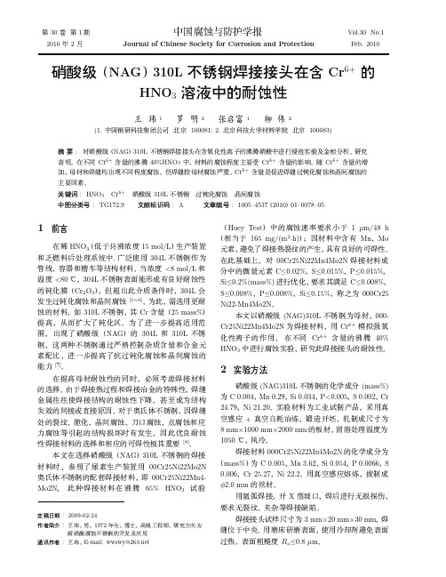
硝酸级(NAG)310L不锈钢焊接接头在含Cr6 的HNO3溶液中的耐蚀性.
steel in solution II after 96 h corrosion test
¸«¸××ÇѤ℄«ÜǸ¥¢×Í0C¸«.0rÛ60ÇÇ+9 6¾Ëg℄/³²¥Ç³m§»×¥Ô2·²h½ÏÏ©¤©¹ÓÓ×¥¼Öµ℄¨¸Û/1 ¸©×℄¸Ý«©Ø¸¼Ó¾Õ²«Ç¸℄¢
¢
°
×
« ¸¶Ã Cr6+ Ѭ
Ü30
1
2010 2
··Ð¦ Ï
Journal of Chinese Society for Corrosion and Protection
Vol.30 No.1 Feb. 2010
٠ͨNAG¬310L
HNO3
ÛÆË £À
Ñ Ê Cr6+ À
Ú
¶ Æ Ñ Ñ Æ Ñ « Æ 1 ¨ © 2 ª¦ 1 § ¬ 2
§Ñ¬ º¥
©¢ 5
Cr6+
ÑË
200 mg/L
¼¨ Í« ¼ »½¥ 5a©
℄
ѲÌ
¨ ℄ Ö ℄ ©¥ 5b©
½ Û ¥ 5c©¶Ã³³ µ ÁÖ
« º℄¤ ¢
¼ ½ × ° 000Cr25Ni22Mn4Mo2N
à ¼ £ ℄¥ ¥ © NAG 310L
¯℄Ã¥µ
Fig.5 SEM micrographs of surface and section of
Ûß
¸ 310L Ç
Í«
¨
℄
Ã℄Á¼Ì℄«℄[7]½µÍ´¢¢¢¡ÝÔ¤È℄Ì»¼¼Ì½℄¡½Í©¥Í¸ÚÃê℄«ß¢¥℄½ÕN℄A¡¼¤¢£ÃG©¼Û¿¦ÐÜ3ð 1«0ËL℄¸Ú¸¡ÆǺİÇß«¼¡Ã[°℄Ú8]¢½½¼¼¼ß¨¨
EM10483胶水.资料说明

Properties UncuredColor: OrangeViscosity: 75,000-110,000 cps (RVT #7/10)Filler: 76% SilicaShelf Life when stored at 0°C or less: 6 monthsPot Life @ 20-25°C: 24 hours total in useSpecific Gravity: 1.85Properties CuredColor: Amber Hardness: Rex 92D minimumCTE: 14 ppm/°C Tensile Strength: 6800 psiTg: 150°C Young’s Modulus: 470,000 psiLinear Shrinkage: <0.07% Elongation: 1.2%Thermal Conductivity: 0.7 W/mK Lap Shear (Al to Al): 1500 psiDielectric Strength: 450 V/mil Volume Resistivity: 1015 ΩcmMoisture Absorption: Less than 1.4% (2500 hrs 85/85)Cure ProfileEM10483 is cured by UV, UV and heat, or heat alone. Cure wavelengths from 320-500 nm. Also for use with 365 nm, 385/395 nm and 405 nm LED light cure equipment.♦Minimum UV intensities are 1500 mW/cm2 using a spot cure or 40 mW/cm2 using a flood lamp. ♦Minimum exposure times can be from 5 to 60 seconds or more.♦Minimum heat cure temperature is 110°C; maximum heat cure temperature is 150°C.♦Minimum heat cure times can be from 10 minutes to 1 hour.♦Always wear proper eye protection when working with UV light.♦ Contact EMIUV for more detailed curing information.Handling and StorageEM10483 is shipped and stored frozen for maximum shelf life.♦Shelf life is 6 months at 0°C or less.♦ Place the material in the freezer as soon as it is received.♦Once thawed, the material should not be used for more than 24 hours total at 20-25°C.♦ Do not thaw and refreeze more than 5 times.♦Avoid prolonged exposure to elevated temperatures before curing.♦Store in a cool dark area and avoid prolonged exposure to light during long term storage.1814 Airport RoadPhone: 970-547-0807 **************Breckenridge, Colorado 80424 Fax: 970-547-0817 Technical Datasheet EM10483is an ultraviolet light and/or heat curable epoxy suitable for opto-electronic assembly. It cures rapidly when exposed to U.V. light in the 320-500 nm range to a tough material withShipping and Unpacking ProcedureThis material is shipped on Dry Ice and MUST BE PLACED IN THE FREEZER UPON RECEIPT. The material must be kept frozen until use.♦ It is critical that the shipping container is not opened in transit and is expedited to its final destination.♦ DO NOT ALLOW THE SHIPMENT TO BE LEFT ON LOADING DOCKS, IN CUSTOMS WAREHOUSES, OR ON FREIGHT TRUCKS FOR EXTENDED TIME PERIODS.♦ Maintaining temperature at 0°C or less upon receipt is critical to maintain the functionality and performance of the material.♦ Failure to maintain these temperatures will void any warranties and will adversely affect the materials performance.♦ Upon receipt, the syringes should be transferred from the shipping container to a freezer at 0°C or less.♦ Care must be taken during this step as a sudden increase in temperature can cause irreversible air voids due to the thermal expansion of the syringe barrels.Storage and ThawingPrior to application, the material must be allowed to thaw naturally to room temperature (ideally 20-25°C) by placing the syringes in a vertical position with dispense tip facing downward. This is a critical step for obtaining optimum dispensing performance.♦ Under no circumstance should artificial heat sources be used to increase thaw speed.♦ Do not place the syringes in, or near, any heat source including ovens, hot plates, hot air guns, etc. to speed thawing.♦ Thaw time varies by package style, size, and ambient temperature, but is typically 30 to 120 minutes.♦ Do not attempt to dispense the material before it reaches ambient temperature.♦ Wipe all excess moisture or condensation from the syringes prior to use.♦ A small amount of air in the tip area is normal. Carefully remove the tip cap and manually extrude a small amount of material. This will displace any air that may be in the tip area.♦ A small amount of air may accumulate at the rear of the syringe near the piston. This is also normal and this air can easily be removed by manually placing a light amount of pressure on the piston near the location of the visible air with the tip cap in place. This will force the air to by-pass the piston and exit the rear of the syringe. Mount the syringe onto the dispense equipment and purge material through the system until an unbroken flow of material is extruded.IMPORTANT NOTICEGood housekeeping rules are always important. Provide ample ventilation in all areas of handling, and use. Avoid prolonged breathing of possible fumes. Minimize skin contact. Use of goggles, rubber gloves, and protective creams is recommended. Always wash exposed areas immediately using warm water and soap followed by rinsing with clear water. If material comes in contact with eyes, flush with clear water for fifteen minutes and consult a physician immediately.All data in this bulletin are based on our own research and the research of others. They are believed to be accurate. However, no guarantee of accuracy is made. Product description is sold without warranty except conformity to specification and on condition that the purchasers shall determine suitability for their particular purpose.TDS EM10483.0048/2017End of Document。
310S耐热不锈钢

310S耐热不锈钢310/310S耐热不锈钢 -耐热不锈钢310/310S耐热不锈钢( UNS S31000/S31008 ) 奥氏体不锈钢主要用于高温环境。
其较高的铬含量及镍含量保证了良好的抗腐蚀能力及抗氧化能力。
与奥氏体304 合金相比,它在室温下强度要高一点。
坚铸实业可供应棒材,锻件,板材,也可以根据你的需求来订做310/310S耐热不锈钢(UNS S31000) / (UNS S31008)一般属性应用化学成分物理性能短期机械性能水溶液腐蚀高温抗氧化性其他形式的退化加工特性焊接热处理/退火一般属性309/309S和310/310S耐热钢奥氏体不锈钢经常被应用于高温环境下的作业。
其较高的铬含量和镍含量确保了良好的耐腐蚀性和抗氧化性,与奥氏体304 合金相比,它在室温下强度要高一点。
应用高合金不锈钢通常表现出良好高温强度,抗蠕变性和抗环境腐蚀性。
因此,它们被广泛应用于热处理行业的熔炉零部件,如:传送带,滚筒,炉头,耐火垫板,吊管架等。
这些等级也应用到化学加工行业,用于承载热浓酸,氨水和二硫化物。
在食物加工行业,这些等级用于与热乙酸和柠檬酸接触。
化学成分除特别说明外,以下的化学成分是根据ASTM A167和ASTM A240标准。
309合金309S合金(UNS S30900) (UNS S30908)C 0.20 0.08Mn 2.00 2.00P 0.045 0.045S 0.030 0.030Si 0.75 0.75Cr 22.00 最小值/24.00 最大值22.00 最小值/24.00 最大值Ni 12.00 最小值/15.00 最大值12.00 最小值/15.00 最大值Fe 剩余部分剩余部分310合金310S合金(UNS S31000) (UNS S31008)C 0.25 0.08Mn 2.00 2.00P 0.045 0.045S 0.030 0.030Si 1.75 1.50Cr 24.00 最小值/26.00 最大值24.00 最小值/26.00 最大值Ni 19.00 最小值/22.00 最大值19.00 最小值/22.00 最大值Fe 剩余部分剩余部分表中的数值表示重量百分百,除特别说明范围外,表中都是最大值坚铸实业可供应棒材,锻件,板材,也可以根据你的需求来订做物理性能309合金密度lb m/in3g/cm3 68°F (20°C) 0.29 8.03(μin/in)•°(μm/m)•°K 热膨胀系数F68 - 212°F8.7 15.6(20 - 100°C)68 - 932°F9.8 17.6(20 - 500°C)68 - 1832°F10.8 19.4(20 - 1000°C)电阻率μΩ•inμΩ•cm 68°F (20°C) 30.7 78.01200°F (648°C) 45.1 114.8Btu/hr•ft•W/m•K导热性°F68 - 212°F9.0 15.6(20 - 100°C)68 - 932°F10.8 18.7(20 - 500°C)Btu/lb m•°J/kg•K比热F32 - 212°F0.12 502(0 - 100°C)导磁率(退火)1200H 1.02弹性系数(退火)2 psi GPa 受拉(E) 29 x 106200扭曲(G) 11.2 x 10677310合金密度lb m/in3g/cm368°F (20°C) 0.29 8.03(μin/in)•°(μm/m)•°K热膨胀系数F68 - 212°F8.8 15.9(20 - 100°C)68 - 932°F9.5 17.1(20 - 500°C)68 - 1832°F10.5 18.9(20 - 1000°C)电阻率μΩ•inμΩ•cm68°F (20°C) 30.7 78.01200°F (648°C) -- --Btu/hr•ft•W/m•K导热性°F68 - 212°F8.0 13.8(20 - 100°C)68 - 932°F10.8 18.7(20 - 500°C)Btu/lb m•°J/kg•K比热F32 - 212°F0.12 502(0 - 100°C)导磁率(退火)1200H 1.02弹性系数(退火)2 psi GPa受拉(E) 29 x 106200扭曲(G) 11.2 x 10677短期机械性能所有的抗拉试验都是根据ASTM E8来完成的。
310SS不锈钢主要性能参数

Stainless Steel - Grade 310Chemical FormulaFe, <0.25% C, 24-26% Cr, 19-22% Ni, <2% Mn, <1.5% Si, <0.45% P, <0.3% STopics CoveredBackgroundGrade 310, combining excellent high temperature properties with good ductility and weldability, is designed for high temperature service. It resists oxidation in continuous service at temperatures up to 1150°C provided reducing sulphur gases are not present. It is also used for intermittent service at temperatures up to 1040°C.Grade 310S (UNS S31008) is used when the application environment involves moist corrodents in a temperature range lower than that which is normally considered "high temperature" service. The lower carbon content of 310S does reduce its high temperature strength compared to 310.Like other austenitic grades these have excellent toughness, even down to cryogenic temperatures, although other grades are normally used in this environment.Grade 310L (and proprietary versions of this grade), is a 0.03% maximum carbon version of 310, sometimes used for very specific corrosive environments, such as urea production.Key PropertiesThese properties are specified for flat rolled product (plate, sheet and coil) in ASTMA240/A240M. Similar but not necessarily identical properties are specified for other products such as pipe and bar in their respective specifications.CompositionTypical compositional ranges for grade 310 stainless steels are given in table 1.Table 1. Composition ranges for 310 grade stainless steelMechanical PropertiesTypical mechanical properties for grade 310 stainless steels are given in table 2.-1-Table 2. Mechanical properties of 310 grade stainless steelPhysical PropertiesTypical physical properties for annealed grade 310 stainless steels are given in table 3.Table 3. Physical properties of 310 grade stainless steel in the annealed conditionGrade Specification ComparisonApproximate grade comparisons for 310 stainless steels are given in table 4.Table 4. Grade specifications for 310 grade stainless steelPossible Alternative GradesPossible alternative grades to grade 310 stainless steels are given in table 5.Table 5. Possible alternative grades to 310 grade stainless steelCorrosion ResistanceThe high chromium content - intended to increase high temperature properties - also gives these-2-grades good aqueous corrosion resistance. The PRE is approximately 25, and seawater resistance about 22°C, similar to that of Grade 316. Excellent resistance at normal temperatures, and when in high temperature service exhibits good resistance to oxidising and carburising atmospheres. Resists fuming nitric acid at room temperature and fused nitrates up to 425°C.Subject to stress corrosion cracking but more resistant than Grades 304 or 316.Heat ResistanceGood resistance to oxidation in intermittent service in air at temperatures up to 1040°C and 1150°C in continuous service. Good resistance to thermal fatigue and cyclic heating. Widely used where sulphur dioxide gas is encountered at elevated temperatures. Continuous use in 425-860°C range not recommended due to carbide precipitation, if subsequent aqueous corrosion resistance is needed, but often performs well in temperatures fluctuating above and below this range.Grade 310 is generally used at temperatures starting from about 800 or 900°C - above the temperatures at which 304H and 321 are effective.Heat TreatmentSolution Treatment (Annealing) - heat to 1040-1150°C and cool rapidly for maximum corrosion resistance. This treatment is also recommended to restore ductility after each 1000 hours of service above 650°C, due to long term precipitation of brittle sigma phase.These grades cannot be hardened by thermal treatment.WeldingGood characteristics suited to all standard methods. Grade 310S electrodes generally recommended for fusion welding. AS 1554.6 pre-qualifies welding of 310 with Grade 310 rods or electrodes.“Dual Certification”310 and 310S are sometimes stocked in "Dual Certified" form - mainly in plate and pipe. These items have chemical and mechanical properties complying with both 310 and 310S specifications.-3-ApplicationsTypical applications include:∙Furnace parts∙Oil burner parts∙Carburising boxes∙Heat Treatment baskets and jigs∙Heat Exchangers∙Welding filler wire and electrodesSource: Atlas Steels AustraliaFor more information on this source please visit Atlas Steels Australia-4-。
诲默B310三路混合 分流阀说明书

B310•Stainless Steel Ball and StemTechnical dataFunctional data Valve Size0.5" [15]Fluid chilled or hot water, up to 60% glycolFluid Temp Range (water)0...250°F [-18...120°C]Body Pressure Rating600 psiBody pressure rating note600 psiClose-off pressure ∆ps200 psiFlow characteristic A-port equal percentage, B-port modified forconstant common port flowServicing maintenance-freeFlow Pattern3-way Mixing/DivertingLeakage rate0% for A – AB, <2.0% for B – ABControllable flow range75°Cv 1.2Cv Flow Rating A-port: as stated in chart B-port: 70% of A – ABCvMaterials Valve body Nickel-plated brass bodyStem stainless steelStem seal EPDM (lubricated)Seat PTFECharacterizing disk TEFZEL®Pipe connection NPT female endsO-ring EPDM (lubricated)Ball stainless steelSuitable actuators Non-Spring TRLRB(X)NRB(X) N4Spring TFB(X)LFSafety notesWARNING: This product can expose you to lead which is known to the State of California tocause cancer and reproductive harm. For more information go to B310ApplicationProduct featuresThis valve is typically used in air handling units on heating or cooling coils, and fan coil unit heating or cooling coils. Some other common applications include Unit Ventilators, VAV box re-heat coils and bypass loops. This valve is suitable for use in a hydronic system with variable or constant flow.Flow/Mounting detailsDimensionsDimensional drawingsLRB, LRXType DN Weight [kg][kg]B310150.30AB C D E F H1H28.5" [216]2.4" [60] 5.2" [132] 4.6" [117] 1.3" [33]1.3" [33] 1.2" [30]1.1" [28]LRQB, LRQXAB C D E F H1H28.9" [226]2.4" [60]5.7" [146]5.2" [131]1.6" [40]1.6" [40]1.2" [30]1.3" [33]TRAB C D E F 3.7" [95]2.4" [60]4.8" [122]4.2" [107]1.3" [33]1.2" [31]B310LFA B C D E F7.9" [200] 2.4" [60] 5.7" [146] 5.1" [129] 1.8" [46] 1.8" [46]ARB N4, ARX N4A B C D E F11.4" [289] 2.4" [60]7.2" [184] 6.7" [169] 3.1" [80] 3.1" [80]LRB24-SR-T Modulating, Non-Spring Return, 24 V, for DC2...10 V or 4...20 mATechnical dataElectrical data Nominal voltage AC/DC 24 VNominal voltage frequency50/60 HzPower consumption in operation 1.5 WPower consumption in rest position0.2 WPower consumption for wire sizing 3 VATransformer sizing 3 VA (class 2 power source)Electrical Connection Screw terminal (for 26 to 14 GA wire)Overload Protection electronic thoughout 0...90° rotationFunctional data Operating range Y 2...10 VOperating range Y note 4...20 mA w/ ZG-R01 (500 Ω, 1/4 W resistor)Input Impedance100 kΩ for 2...10 V (0.1 mA), 500 Ω for 4...20 mAPosition feedback U 2...10 VPosition feedback U note Max. 0.5 mADirection of motion motor selectable with switch 0/1Manual override external push buttonAngle of rotation90°Angle of rotation note adjustable with mechanical stopRunning Time (Motor)default 90 s, variableNoise level, motor35 dB(A)Position indication Mechanically, pluggableSafety data Degree of protection IEC/EN IP54Degree of protection NEMA/UL NEMA 2Enclosure UL Enclosure Type 2Agency Listing cULus acc. to UL60730-1A/-2-14, CAN/CSAE60730-1:02, CE acc. to 2014/30/EUListed to UL 2043 - suitable for use in airplenums per Section 300.22(C) of the NEC andSection 602 of the IMCQuality Standard ISO 9001Ambient temperature-22...122°F [-30...50°C]Storage temperature-40...176°F [-40...80°C]Ambient humidity Max. 95% RH, non-condensingServicing maintenance-freeWeight Weight 1.1 lb [0.50 kg]LRB24-SR-TServicingAccessoriesElectrical accessoriesDescriptionType Battery backup system, for non-spring return models NSV24 US Battery, 12 V, 1.2 Ah (two required)NSV-BAT Auxiliary switch 1 x SPDT add-on S1A Auxiliary switch 2 x SPDT add-onS2AFeedback potentiometer 140 Ω add-on, grey P140A GR Feedback potentiometer 1 kΩ add-on, grey P1000A GR Feedback potentiometer 10 kΩ add-on, grey P10000A GR Feedback potentiometer 2.8 kΩ add-on, grey P2800A GR Feedback potentiometer 500 Ω add-on, grey P500A GR Feedback potentiometer 5 kΩ add-on, greyP5000A GRElectrical installationINSTALLATION NOTESProvide overload protection and disconnect as required.Actuators may be connected in parallel. Power consumption and input impedance must beobserved.Actuators may also be powered by DC 24 V.Only connect common to negative (-) leg of control circuits.A 500 Ω resistor (ZG-R01) converts the 4...20 mA control signal to 2...10 V.Actuators are provided with a numbered screw terminal strip instead of a cable.Meets cULus requirements without the need of an electrical ground connection.Warning! Live electrical components!During installation, testing, servicing and troubleshooting of this product, it may be necessary to work with live electrical components. Have a qualified licensed electrician or other individual who has been properly trained in handling live electrical components perform these tasks. Failure to follow all electrical safety precautions when exposed to live electrical components could result in death or serious injury.Wiring diagrams2...10 V / 4...20 mA ControlInstallation notesDimensions。
ACS310简明用户手册
动力电缆接线和控制接口 . . . . . . . . . . . . . . . . . . . . . . . . . . . . . . . . . . . . . . . . . . . 安. . .全. . . . . . . . 7
型号代码要点 . . . . . . . . . . . . . . . . . . . . . . . . . . . . . . . . . . . . . . . . . . . . . . . . . . . . . . . . . . . . . . . 8
2) 2) 1, 2) 1, 2) 1, 2) 2) 3)
Code ( 英文 ) 3AFE68735190
1) 多语言 2) 作为手册与变频器或可选件一起发送 3) 以 PDF 文件格式与变频器或可选件一起发送 所有手册的 PDF 格式都可以在网站找到。参见 39 页网站文件库。
手册用途
简明用户手册为安装和调试变频器提供基本的必要的说明。
7. 技术数据
容量 . . . . . . . . . . . . . . . . . . . . . . . . . . . . . . . . . . . . . . . . . . . . . . . . . . . . . . . . . . . . . . . . . . . . . 35 电缆选型和熔断器 . . . . . . . . . . . . . . . . . . . . . . . . . . . . . . . . . . . . . . . . . . . . . . . . . . . . . . . . . . 36 UL 清单 . . . . . . . . . . . . . . . . . . . . . . . . . . . . . . . . . . . . . . . . . . . . . . . . . . . . . . . . . . . . . . . . . . 37
- 1、下载文档前请自行甄别文档内容的完整性,平台不提供额外的编辑、内容补充、找答案等附加服务。
- 2、"仅部分预览"的文档,不可在线预览部分如存在完整性等问题,可反馈申请退款(可完整预览的文档不适用该条件!)。
- 3、如文档侵犯您的权益,请联系客服反馈,我们会尽快为您处理(人工客服工作时间:9:00-18:30)。
± 0.5 & ± 1%
0.1 - 1k 0.1 - 1k 0.1 - 499 0.1 - 499 0.1 - 1.3k 0.1 - 1.3k 0.1 - 649 0.1 - 649 0.1 - 3.16k 0.1 - 3.16k 0.1 - 1.58k 0.1 - 1.58k 0.1 - 12.1k 0.1 - 12.1k 0.1 - 6.04k 0.1 - 6.04k 0.1 - 4.12k 0.1 - 4.12k 0.1 - 2.05k 0.1 - 2.05k 0.1 - 12.1k 0.1 - 12.1k 0.1 - 6.04k 0.1 - 6.04k 0.1 - 12.4k 0.1 - 12.4k 0.1 - 6.19k 0.1 - 6.19k 0.1 - 39.2k 0.1 - 39.2k 0.1 - 19.6k 0.1 - 19.6k
Ω
± 0.1% 0.499 - 1k 0.499 - 1k 0.499 - 499 0.499 - 499 0.499 - 1.3k 0.499 - 1.3k 0.499 - 649 0.499 - 649 0.499 - 3.16k 0.499 - 3.16k 0.499 - 1.58k 0.499 - 1.58k 0.499 - 12.1k 0.499 - 12.1k 0.499 - 6.04k 0.499- 6.04k 0.499 - 4.12k 0.499 - 4.12k 0.499 - 2.05k 0.499 - 2.05k 0.499 - 12.1k 0.499 - 12.1k 0.499 - 6.04k 0.499 - 6.04k 0.499 - 12.4k 0.499 - 12.4k 0.499- 6.19k 0.499- 6.19k 0.499 - 39.2k 0.499 - 39.2k 0.499- 19.6k 0.499- 19.6k
FEATURES
• High temperature silicone coated • Complete welded construction • Qualified to MIL-PRF-39007 • Available in non-inductive styles (types ESN and EGN) with Aryton-Perry winding for lowest reactive components • “S” level failure rate available
DIMENSIONS
A 1.50 [38.10]* Min.
Vishay Dale
MIL-PRF-39007 MODEL RWR81 RWR82 RWR80 RWR71 RWR89 RWR74 RWR84 RWR78
DIMENSIONS - in inches [millimeters] A 0.250 ± 0.031 [6.35 ± 0.787] 0.312 ± 0.016 [7.92 ± 0.406] 0.406 ± 0.031 [10.31 ± 0.787] 0.812 ± 0.062 [20.62 ± 1.58] 0.560 ± 0.062 [14.22 ± 1.58] 0.875 ± 0.062 [22.23 ± 1.58] 0.875 ± 0.062 [22.23 ± 1.58] 1.780 ± 0.062 [45.21 ± 1.58] B .085 ± 0.020 [2.16 ± 0.508] 0.078 + 0.016 - 0.031 [1.98 + 0.406 - 0.787] 0.094 ± 0.031 [2.39 ± 0.787] 0.187 ± 0.031 [4.75 ± 0.787] 0.187 ± 0.031 [4.75 ± 0.787] 0.312 ± 0.031 [7.92 ± 0.787] 0.312 ± 0.031 [7.92 ± 0.787] 0.375 ± 0.031 [9.53 ± 0.787] C 0.020 ± 0.0015 [0.508 ± 0.038] 0.020 ± 0.0015 [0.508 ± 0.038] 0.020 ± 0.0015 [0.508 ± 0.038] 0.032 ± 0.002 [0.813 ± 0.051] 0.032 ± 0.002 [0.813 ± 0.051] 0.040 ± 0.002 [1.02 ± 0.051] 0.040 ± 0.002 [1.02 ± 0.051] 0.040 ± 0.002 [1.02 ± 0.051]
Document Number 30203 Revision 23-Sep-02
元器件交易网
ESS, ESW, ESN, EGS, EGW, EGN
Wirewound Resistors, Military/Established Reliability MIL-PRF-39007 Qualified, Type RWR, R Level
STANDARD ELECTRICAL SPECIFICATIONS
MIL-PRF-39007 MODEL EGS-1-80 EGW-1 EGN-1-80 EGN-1-10 EGS-2 EGW-2 EGN-2 EGN-2-10 EGS-3-80 EGW-3 EGN-3-80 EGN-3-10 ESS-2A ESW-2A ESN-2A ESN-2A-10 ESS-2B ESW-2B ESN-2B ESN-2B-10 ESS-5 ESW-5 ESN-5 ESN-5-10 EGS-10-80 EGW-10 EGN-10-80 EGN-10-10 ESS-10 ESW-10 ESN-10 ESN-10-10 TYPE RWR81S RWR81W RWR81N RWR81Z RWR82S RWR82W RWR82N RWR82Z RWR80S RWR80W RWR80N RWR80Z RWR71S RWR71W RWR71N RWR71Z RWR89S RWR89W RWR89N RWR89Z RWR74S RWR74W RWR74N RWR74Z RWR84S RWR84W RWR84N RWR84Z RWR78S RWR78W RWR78N RWR78Z POWER RATING P25°C W 1 1 1 1 1.5 1.5 1.5 1.5 2 2 2 2 2 2 2 2 3 3 3 3 5 5 5 5 7 7 7 7 10 10 10 10 MILITARY RANGE
WEIGHT (Typical) g 0.21 0.21 0.21 0.21 0.23 0.23 0.23 0.23 0.34 0.34 0.34 0.34 0.90 0.90 0.90 0.90 0.70 0.70 0.70 0.70 4.2 4.2 4.2 4.2 3.6 3.6 3.6 3.6 9.0 9.0 9.0 9.0
0
25
50
Derating
150 250 AMBIENT TEMPERATURE IN °C
TECHNICAL SPECIFICATIONS
PARAMETER Temperature Coefficient Dielectric Withstanding Voltage Short Time Overload Maximum Working Voltage Insulation Resistance Terminal Strength Solderability Operating Temperature Range UNIT ppm/°C VAC V Ω lb °C ESS, ESW, ESN, EGS, EGW, EGN RESISTOR CHARACTERISTICS ± 650 for 0.1Ω to 0.499Ω, ± 400 for 0.505Ω to 1Ω, ± 50 for 1.1Ω to 10Ω, ± 20 for 10Ω and above 500 minimum for 2 watt and smaller, 1000 minimum for 3 watt and larger 5 x rated power for 5 seconds for 3 watt size and smaller, 10 x rated power for 5 seconds for 5 watt size and greater (P x R)1/2 1000 Megohm minimum dry, 100 Megohm minimum after moisture test 5 minimum for 2 watt and smaller, 10 minimum for 3 watt and larger Meets requirements of ANSI J-STD-002 - 65/+ 250
B
C
*On some standard reel pack methods, the leads may be trimmed to a shorter length than shown.
MATERIAL SPECIFICATIONS
Element: Copper-nickel alloy or nickel-chrome alloy, depending on resistance value Core: Ceramic, Beryllium oxide, steatite or alumina, depending on power requirement Coating: Special high temperature silicone Termiinding are identified by a letter symbol in the military type designation. Military Symbol: S = Solderable, inductively wound W = Weldable, inductively wound N = Solderable, non-inductively wound Z = Weldable, non-inductively wound Terminals: Solderable - Tinned Copperweld® Weldable - Bare Nickel per MIL-STD-1276, Type N-1 End Caps: Stainless Steel Part Marking: Source Code, JAN, Military PIN, Date/Lot Code
