关于pci简易控制器驱动安装
戴尔PCI Express DVI(数字)适配卡安装和设置指南说明书

PCI Express DVI (Digital) Adapter Card Installation and Setup GuideThe Digital Visual Interface (DVI) adapter card, using the integrated graphics controller on your computer, provides a DVI port. The DVI port provides a direct, digital connection to a digital display, such as a digital flat panel display. The DVI adapter works through the integrated graphics on your computer and is controlled through the integrated graphics driver's user interface, which is located under the Control Panel in Microsoft ® Windows ® operating systems. The DVI adapter plugs into the PCI Express x16 slot on your system board.Safety InstructionsInstallation InstructionsTroubleshootingSpecificationsRegulatory NoticesNotes, Notices, and CautionsInformation in this document is subject to change without notice.© 2004 Dell Inc. All rights reserved.Reproduction in any manner whatsoever without the written permission of Dell Inc. is strictly forbidden.Trademarks used in this text: Dell and the DELL logo are trademarks of Dell Inc.; Microsoft, Windows , and Windows NT are registered trademarks of Microsoft Corporation; Intel is a registered trademark of Intel Corporation.Other trademarks and trade names may be used in this document to refer to either the entities claiming the marks and names or their products. Dell Inc. disclaims anyproprietary interest in trademarks and trade names other than its own.December 2004 Rev. A01NOTE: A NOTE indicates important information that helps you make better use of your computer.NOTICE: A NOTICE indicates either potential damage to hardware or loss of data and tells you how to avoid the problem.CAUTION: A CAUTION indicates a potential for property damage, personal injury, or death.1hinged lever 2filler bracket1card notch2card-clip lever 3card-clip tab 4card clip1card cage2handle3.Remove the filler bracket to create an empty card-slot opening in the card cage:a. Press the release tab at the top of the card cage.1release tab2card retention lever3card slotNOTE: See the documentation that came with the card for information on configuring the card, making internal connections, or customizing it for your computer.1DVI card2card retention lever3securing slot (not all cards)4securing tab5card connector1card cage2slots3riser boards (2)4system board connectors (2)1DVI card2card retention lever3securing slot (not on all cards) 4securing tab5card connector1card notch2card-clip lever 3card-clip tab 4card clip1card notch1hinged lever 2filler bracket1card notch2card-clip leverBack to Contents PageRegulatory Notices: PCI Express DVI (Digital) Adapter CardPCI Express DVI (Digital) Adapter Card Installation and Setup GuideFCC Notices (U.S. Only)This equipment has been tested and found to comply with the limits for a Class B digital device pursuant to Part 15 of the FCC Rules. These limits are designed to provide reasonable protection against harmful interference in a residential installation. This equipment generates, uses, and can radiate radio frequency energy and, if not installed and used in accordance with the manufacturer's instruction manual, may cause interference with radio communications.This device complies with Part 15 of the FCC Rules. Operation is subject to the following two conditions:lThis device may not cause harmful interference. l This device must accept any interference received, including interference that may cause undesired operation.Class BThis equipment has been tested and found to comply with the limits for a Class B digital device pursuant to Part 15 of the FCC Rules. These limits are designed to provide reasonable protection against harmful interference in a residential installation. This equipment generates, uses, and can radiate radio frequency energy and, if not installed and used in accordance with the manufacturer's instruction manual, may cause interference with radio communications. However, there is no guarantee that interference will not occur in a particular installation. If this equipment does cause harmful interference to radio or televisionreception, which can be determined by turning the equipment off and on, you are encouraged to try to correct the interference by one or more of the following measures:lReorient or relocate the receiving antenna. lIncrease the separation between the equipment and the receiver. lConnect the equipment into an outlet on a circuit different from that to which the receiver is connected. l Consult the dealer or an experienced radio/television technician for help.IC Notice (Canada Only)Most Dell computer systems (and other Dell digital apparatus) are classified by the Industry Canada (IC) Interference-Causing Equipment Standard #3 (ICES-003) as Class B digital devices. To determine which classification (Class A or B) applies to your computer system (or other Dell digital apparatus), examine all registration labels located on the bottom or the back panel of your computer (or other digital apparatus). A statement in the form of "IC Class A ICES-003" or "IC Class B ICES-003" will be located on one of these labels. Note that Industry Canada regulations provide that changes or modifications not expressly approved by Dell could void your authority to operate this equipment.CE Notice (European Union) Marking by the symbol indicates compliance of this product to the EMC Directive and the Low Voltage Directive of the European Union. It meets thefollowing technical standards: EN 55022 Class B and EN 55024: 1998. MIC (Republic of Korea Only)Class B DevicePlease note that this device has been approved for nonbusiness purposes and may be used in any environment, including residential areas.MIC Class B Regulatory LabelIf the regulatory label includes the following marking, your computer is a Class B product:This Class B (or Class A, if so indicated on the registration label) digital apparatus meets the requirements of the Canadian Interference-Causing Equipment Regulations.Cet appareil numérique de la Classe B (ou Classe A, si ainsi indiqué sur l'étiquette d'enregistration) respecte toutes les exigences du Reglement sur le Materiel Brouilleur du Canada.BSMI Notice (Taiwan Only)If you find a or mark on the regulatory label on the bottom, side, or back panel of your computer, the following section is applicable:Back to Contents PageBack to Contents PageSafety InstructionsPCI Express DVI (Digital) Adapter Card Installation and Setup GuideUse the following safety guidelines to help protect your computer from potential damage and to help ensure your own personal safety.When Working Inside Your ComputerBefore you open the computer cover, perform the following steps in the sequence indicated.1. Perform an orderly computer shutdown using the operating system menu.2. Turn off your computer and any devices.3. Ground yourself by touching an unpainted metal surface on the chassis, such as the metal around the card-slot openings at the back of the computer,before touching anything inside your computer.While you work, periodically touch an unpainted metal surface on the computer chassis to dissipate any static electricity that might harm internalcomponents.4. Disconnect your computer and devices from their power sources. Also, disconnect any telephone or telecommunication lines from the computer.Doing so reduces the potential for personal injury or shock.In addition, take note of these safety guidelines when appropriate:lWhen you disconnect a cable, pull on its connector or on its strain-relief loop, not on the cable itself. Some cables have a connector with locking tabs; if you are disconnecting this type of cable, press in on the locking tabs before disconnecting the cable. As you pull connectors apart, keep them evenly aligned to avoid bending any connector pins. Also, before you connect a cable, make sure both connectors are correctly oriented and aligned. l Handle components and cards with care. Do not touch the components or contacts on a card. Hold a card by its edges or by its metal mounting bracket. Hold a component such as a microprocessor chip by its edges, not by its pins.Protecting Against Electrostatic DischargeStatic electricity can harm delicate components inside your computer. To prevent static damage, discharge static electricity from your body before you touch any of your computer's electronic components, such as the microprocessor. You can do so by touching an unpainted metal surface on the computer chassis. As you continue to work inside the computer, periodically touch an unpainted metal surface to remove any static charge your body may have accumulated. You can also take the following steps to prevent damage from electrostatic discharge (ESD):lWhen unpacking a static-sensitive component from its shipping carton, do not remove the component from the antistatic packing material until you are ready to install the component in your computer. Just before unwrapping the antistatic packaging, be sure to discharge static electricity from your body. lWhen transporting a sensitive component, first place it in an antistatic container or packaging. l Handle all sensitive components in a static-safe area. If possible, use antistatic floor pads and workbench pads.Back to Contents PageCAUTION: Do not attempt to service the computer yourself, except as explained in your online Dell documentation or otherwise provided to you. Always follow installation and service instructions closely.NOTICE: To help avoid possible damage to the system board, wait 5 seconds after turning off the computer before removing a component from the system board or disconnecting a device from the computer.CAUTION: There is a danger of a new battery exploding if it is incorrectly installed. Replace the battery only with the same or equivalent type recommended by the manufacturer. Discard used batteries according to the manufacturer's instructions.Back to Contents PageTroubleshooting: PCI Express DVI (Digital) Adapter CardPCI Express DVI (Digital) Adapter Card Installation and Setup Guide1.If the computer detects the card and lists it in the Device Manager, ensure that the advanced graphics setting and options on the Intel® GMA DriverControl Panel are set correctly for the video configuration that you want.2.Verify proper connection between the monitor video cable and the DVI card port.3.Attach a CRT monitor to the VGA connection to ensure that the system is producing a video signal using the integrated controller.4.If the monitor is capable of both VGA and DVI input, ensure that the input selector on the monitor is set correctly.5.If the card is not properly detected, reseat the DVI card in the PCI Express x16 slot to ensure a good connection.See the Installation Instructions.6.If available, test the DVI card by installing the card into a same-model system with a properly working PCI Express x16 slot.7.If available, place a properly working DVI card in the computer to test the PCI Express x16 slot.Back to Contents Page。
ZCCT理论考试答案2024
1客户在公有云中购买了一个Mysql数据库实例,客户获得的是云计算的哪种服务模式?A. IaaS 基础架构即服务B. PaaS 平台即服务C. SaaS 软件即服务D. DaaS 数据即服务区别于传统物理服务器部署模式,虚拟化技术没有解决下面哪一项问题?A. 提高服务器资源利用率B. 节省机柜空间、减少电力消耗等C. 减少服务器数量D. 提高了业务系统的运行性能同一集群内某计算节点故障,上面虚拟化能够在其他节点自动启动,这是下面哪个技术的功能描述?A. 热迁移B. 动态资源调度C. 热升级D. 高可用网络功能虚拟化不包含以下哪些服务?A. 虚拟防火墙B. 网络专线C. 虚拟负载均衡D. 虚拟路由器建设云平台,考虑到未来扩展能力,应该首选哪种存储架构?A. SAN存储B. 分布式存储C. 本地存储D. 以上都可以以下哪一项不是云平台管理方面的典型功能A. 多租户管理B. 多区域管理C. 热迁移D. 异构平台管理公有云弹性、灵活且低成本,是目前企业客户上云选择不同云交付方式的最佳选择。
A. 正确B. 错误通过云服务商购买一台云主机获得IaaS基础即服务后,不需要再考虑基础硬件、机房环境等因素了。
A. 正确B. 错误用的物理网络设备如交换机、路由器、防火墙、入侵检测等都可以以网络功能虚拟化的方式在云环境中进行实现。
A. 正确B. 错误分布式存储技术发展迅速,可扩展能力强、不存在单点故障,将在各种场景中逐渐取代SAN存储的位置。
A. 正确B. 错误虚拟化解决方案与云平台解决方案没有本质上的区别,都是资源池化和资源调度的技术。
A. 正确B. 错误多租户管理通过网络隔离技术、资源隔离技术以及计量计费能够实现不同用户获得完全独立的资源配额且独立计费,互不影响。
A. 正确B. 错误2以下哪一项是ZStack产品化的愿景?A. 软件定义数据中心B. 让每一家企业都拥有自己的云C. 计算无边界D. 产业智变、云启未来云计算产品众多,区别于其他友商,以下哪一项不是ZStack产品的核心特点?A. 简单,一键下载、30分钟部署B. 稳定,承载业务场景广泛C. 功能强大,包含大数据、人工智能等功能D. 智能,能够提供无缝升级以下哪一项服务不是由ZStack提供,而是由第三方合作伙伴提供的产品与方案?A. ZStack云平台B. ZStack Mini软硬件一体机C. ZStack 分布式存储D. ZStack VDI解决方案ZStack云平台可以管理以下哪一个厂商的虚拟化产品?A. VMware vSphereB. 华为FusionSphereC. 深信服aCloudD. H3C CAS以下哪所高校是ZStack所服务过的客户?A. 厦门大学B. 南京大学C. 重庆大学D. 上海大学ZStack云平台能够大幅度提升运维效率,从而容易让企业IT管理运维人员面临失业的风险。
PCI软件安装与启动
PCI软件安装与启动一、一、PCI软件的安装1、1、关机,将PCI软件锁插到打印口;2、启动计算机;3、安装前,关闭所有应用程序;4、将PCI软件安装盘放入光盘驱动器,等待几秒钟;5、按照提示步骤将PCI软件安装到指定目录;6、对于ACE,打开资源管理器,双击光盘上的安装目录Acew95nt\Setup应用程序,按照提示步骤将ACE单独安装在某一目录。
也可安装在PCI_V70目录下;7、启动PCI软件(方法见后),在License Manager模块输入购买的License;或者通过“开始”菜单下“程序”找到PCI Geomatics V7.0下License Manager,也可输入License;8、重新启动计算机。
9、关于浮动License的安装详情请见安装指南,以下是几个要点:(1)在服务器端为客户端开设帐号;(2)在服务器端选择PCI服务器选项安装;(3)在服务器端为客户端设置环境变量指向服务器License所在路径;(4)打开服务器端的服务,启动PCI License Server;(5)在客户端选择PCI完整或瘦型选项安装;(6)在客户端设置浮动License的路径;(7)对于ACE,需要单独安装,服务器端License可以从\PCI_V70\etc\license.dat复制,客户端需要在Windows“开始”菜单“运行”“sysedit”命令,在Autoexec.bat中写入前面环境变量指向的浮动License路径。
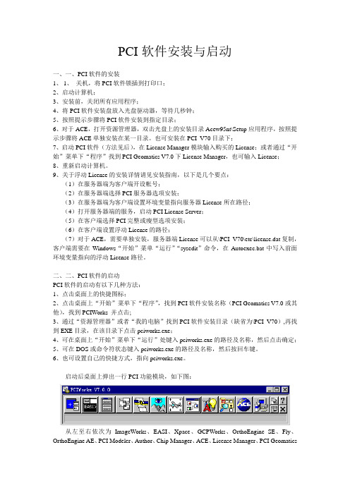
二、二、PCI软件的启动PCI软件的启动有以下几种方法:1、点击桌面上的快捷图标;2、点击桌面上“开始”菜单下“程序”,找到PCI软件安装名称(PCI Geomatics V7.0或其他),找到PCIWorks 并点击;3、通过“资源管理器”或者“我的电脑”找到PCI软件安装目录(缺省为\PCI_V70),再找到EXE目录,在该目录下点击pciworks.exe;4、可在桌面上“开始”菜单下“运行”处键入pciworks.exe的路径及名称,然后点击确定;5、可在DOS或命令符状态键入pciworks.exe的路径及名称,然后按回车键。
B-LINK PCI、PCI-E网卡驱动安装方法与步骤
B-LINK PCI/PCI-E网卡驱动安装方法与步骤
B-LINK PCI/PCI-E网卡使用11N无线技术,无线传输速率最高达150Mbps。
相比传统的54Mbps 11b/g产品,拥有更高的无线带宽,让局域网内的数据传输更加高效,能有效地减少网络延迟,使语音视频,网络游戏,在线点播更流畅。
支持WPA-PSK/WPA2-PSK、WPA/WPA2安全机制和WEP加密,全方位地保护无线网络不被侵犯和盗用。
拥有QSS快速安全设置功能,符合WPS标准。
WPS功能的无线路由使用时,只需在电脑上输入路由器的PIN码,即可完成比传统WEP加密更安全的WPA2级无线安全连接,不需要再记忆复杂的密码。
PCI/PCI-E网卡驱动安装方法与步骤
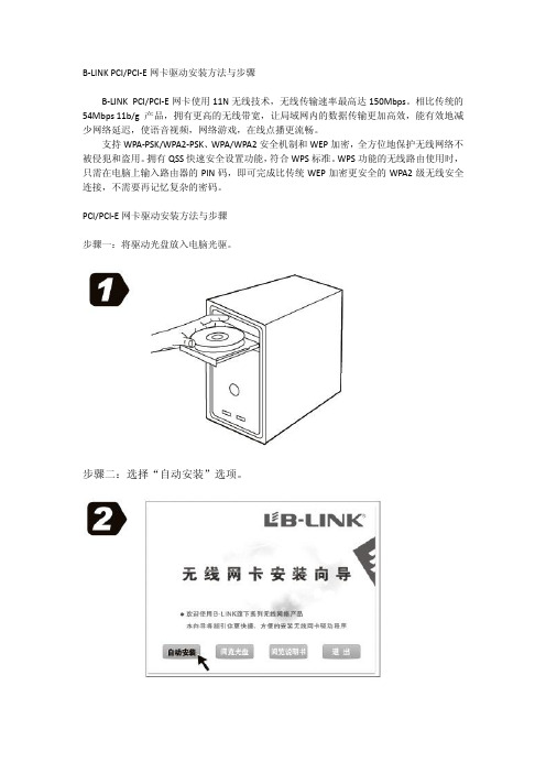
步骤一:将驱动光盘放入电脑光驱。
步骤二:选择“自动安装”选项。
步骤三:选择“接受许可证协议中的条款”,点击“下一步”。
步骤四:选择“安装驱动程序与B-LINK无线网络设定程序”,点击“下一步”。
步骤五:选择“B-LINK无线网络设定程序”,点击“下一步”。
步骤六:选择“安装”。
步骤七:等待软件安装完成。
步骤八:点击“完成”。
nt 2000pci设备驱动程序详解
常常有朋友问我关于pci驱动程序的问题,但是在和他们的交谈中我发现有一些问题非常重复,也没有什么特别的地方(真有什么特别的地方,我也搞不定:-)),对于一些问题,其实卡的结构非常普通,只要熟悉pci驱动程序的一些基本概念就可以解决的。
下面我把pci驱动程序的一些基本概念整理整理:首先讲一讲pci的配置空间。
这个概念本来是非常简单的,但是我这个有灌水的爱好,为了让文章能够更成体系,加上这一段。
pci的配置空间的结构不在这里重复,任何一本pci的书里都有。
对于pci的配置空间操作,我用过的操作系统中,linux下是最简单的,linux提供了许多函数,细节可看linux device driver。
我在这里简单的给出一个操作x86结构下pci的方法就结束这一段。
我在写第一个pci driver的时候是在dos下,最早我操作pci的方法就是用int 1a,需要bios支持,现在的主板是没有不支持得了。
后来我发现了另外一种方法,更为简单,int 1a的方法就记不得了,如果想知道,可以去查int 1a中断,要96年以后的书(int 1a是时钟,但是扩展为pci操作)。
由于不同操作系统提供的函数不同,使得代码可移植性变差,其实这些实现几乎都是基于BIOS的int 1a中断调用。
由于在不同系统中调用1a中断的实现也很不相同,而且一般都需要写驱动程序。
下面是我写的一个通用的操作PCI 配置空间的程序如下,该方法和int 1a内部机制相同,都是基于PCI规范实现的,只用到了端口操作。
代码如下:#include "stdio.h"#include "windows.h"DWORD DWORD_In(WORD io_Port){ DWORD val;_asm {mov dx,io_Portin eax,dxmov val,eax}return val;}DWORD DWORD_Out(WORD io_Port,DWORD val){_asm {mov dx,io_Portmov eax,valout dx,eax}return 0;}int main(){DWORD io_CF8; // port 0xcf8DWORD io_CFC; // port 0xcfcint i;io_CF8=0x80000000; //because the first bit is enable/disablefor(;;) //so must be 1,so from 0x800000000{DWORD_Out(0xcf8,io_CF8);io_CFC=DWORD_In(0xcfc);if (io_CFC!=0xffffffff) //if =0xffffffff,then is a invalid{ //bus number and device numberprintf(" PCI device has found,the pci config address=%lx ",io_CF8);printf("its Bus Numer is %lx ",(io_CF8&0x00ff0000)/0x10000);printf("its Device Number is %lx ",(io_CF8&0x0000f800)/0x800);printf("its Functin Number is %lx ",(io_CF8&0x700)/0x100);printf("this device's deviceID and vendorID=%lx ",io_CFC);for (i=0 ;i<=15;i++){DWORD_Out(0xcf8,io_CF8+4*i); //read DWORDswitch (i){case 0:printf("Device Number and Vendor Number =%lx");break;case 1:printf("Status and Command =");break;case 2:printf("Class Code and Revision ID=");break;case 3:printf("Bist and Header Type and Latency Timer and Cacne LineSize=");break;case 4: //PCI Configration has 6 base addresscase 5: //registercase 6:case 7:case 8:case 9:printf("Base Address Register=");break;case 10:case 11:case 13:case 14:printf("Reserved =");break;case 12:printf("Expansion ROM Base Address=");break;case 15: //attention:the interrupt IRQ= this result&0xffprintf("Max_Lat Min_Gnt Interrupt Pin Interrupt line=");break;}printf("%lx ",DWORD_In(0xcfc));}}io_CF8+=0x800;if (io_CF8>=0x80FFFF00)break;}return 0;} 这个程序是我97年的时候写的,后来就没有改过,在各种场合下用过很多次,我一般在写pcidriver for 9x/nt的时候都要先用它来scan一遍pci空间,看看硬件有没有问题。
Win7中如何解决PCI简易通讯控制器的驱动安装
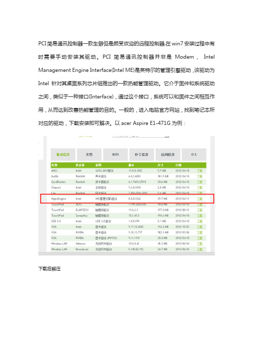
PCI简易通讯控制器一款生僻但是颇受欢迎的远程控制器,在win7安装过程中有时需要手动安装其驱动。
PCI简易通讯控制器并非是Modem,Intel Management Engine Interface(Intel ME)是英特尔的管理引擎驱动,该驱动为Intel针对其桌面系列芯片组推出的一款热能管理驱动。
它介于固件和系统驱动之间,类似于一种接口(Interface),通过这个接口,系统可以和固件之间相互作用,从而达到改善热能管理的目的。
一般的,进入电脑官方网站,找到笔记本所对应的驱动,下载安装即可解决。
以acer Aspire E1-471G为例:
下载后解压
找到Setup.exe进行安装即可。
PCI-Install

PCI设备硬件驱动通用安装说明目 录目 录 (1)第一章硬件驱动的安装(主要指手动安装) (2)第一节Windows98环境下PCI设备驱动程序安装 (2)第二节 Windows2000、XP环境下PCI设备及驱动程序安装 (5)第二章演示及测试程序的安装(也包括硬件驱动的自动安装) (9)第一节 安装方法 (9)第二节 程序的使用 (9)第三章产品二次开发注意事项 (9)第一节 本驱动程序软件的关键文件 (9)第二节 产品二次发行 (10)第一章硬件驱动的安装(主要指手动安装)第一节Windows98环境下PCI设备驱动程序安装任意PCI设备驱动程序在同一系统下的安装步骤相同。
下面是以PCI8020在Windows 98为例演示安装步骤:一、安装步骤第一步将PCI设备按硬件要求插入计算机主板上的任意一个PCI插槽中,并将其固定好,连接好其外接设备后,打开计算机电源,启动Windows 98系统。
第二步如果您正确地插好了PCI设备,Windows系统在启动过程中便会发现这个新的PCI设备,并弹出“找到新硬件”的对话框,几秒钟后,便进入“添加新硬件向导”对话框的第一步,它告之所发现的新硬件的设备类型为“Art PCI8020….”相关信息,然后,选择“指定驱动程序的位置(高级)”,然后请单击“下一步”按钮。
第三步“添加新硬件向导”对话框的第二步,询问您是自动搜索PCI的驱动程序,还是手工从列表中选择。
您最好单选第二个选项“显示指定位置的所有驱动程序列表,以便可从列表中选择所需的驱动程序”,如图1,然后单击“下一步”按钮.图 1第五步 “添加新硬件向导”对话框的第三步是在列表中选择具体的设备名,此处您应单击“从软盘安装”按钮,“从软盘安装”对话框,单击“浏览”,如果从软盘安装,将路径定位在“A:\INF”中,如果从光盘安装,将路径定位在光盘上的\PCI\PCI8020\\INF\ WIN9X路径下,选择PCI8020.INF文件。
关于pci简易控制器驱动安装

关于PCI简易通讯控制器和Turbo驱动的安装方法
答:
Intel 5系列芯片组机型在设备管理器里出现“PCI简易通讯控制器”或者Intel(R) Turbo Boost Technology Driver上出现打叹号或打问号:
首先要查看设备范例ID :
在“我的电脑”上点击右键,选择“属性”,选择“硬件”选项卡,选择“设备管理器”,在弹出窗口中找到带有黄色问号或是感叹号的设备,在该设备点击右键,选择“属性”,选择“详细信息”选项卡,查看“设备范例ID”所列出的值。
1、若设备范例ID 为VEN_8086 DEV_3B64
可下载,PCI简易通讯控制器XP、Windows7驱动:
ftp://fuwuzhan:fuwuzhan@/drivers/mei_intel_6001179.zip
2、若设备范例ID 为VEN_8086 DEV_3B32
在上面点击右键,手动更新驱动程序,从磁盘安装,指引到主板驱动ALL 目录的ibexiips.inf 文件
确定后,即可安装驱动。
Intel Dialogic D 41JCT-LS PCI安装卡快速安装指南说明书
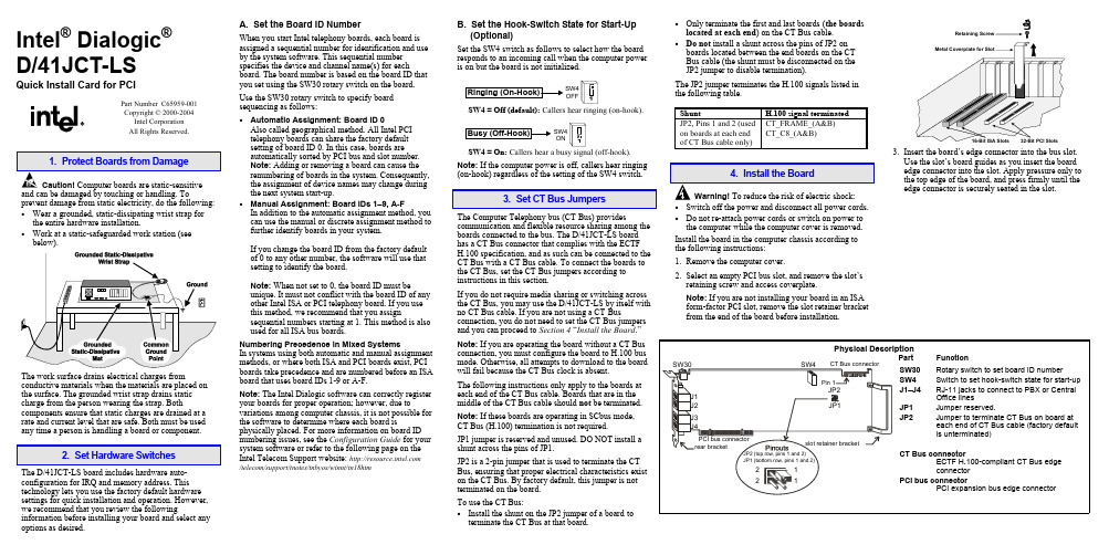
Intel® Dialogic®D/41JCT-LSQuick Install Card for PCIPart Number C65959-001Copyright © 2000-2004Intel CorporationAll Rights Reserved.prevent damage from static electricity, do the following:• Wear a grounded, static-dissipating wrist strap forthe entire hardware installation.• Work at a static-safeguarded work station (seebelow).The work surface drains electrical charges from conductive materials when the materials are placed on the surface. The grounded wrist strap drains static charge from the person wearing the strap. Both components ensure that static charges are drained at a rate and current level that are safe. Both must be used any time a person is handling a board or component.2. Set Hardware SwitchesThe D/41JCT-LS board includes hardware auto-configuration for IRQ and memory address. This technology lets you use the factory default hardware settings for quick installation and operation. However, we recommend that you review the following information before installing your board and select any options as desired.A. Set the Board ID NumberWhen you start Intel telephony boards, each board isassigned a sequential number for identification and useby the system software. This sequential numberspecifies the device and channel name(s) for eachboard. The board number is based on the board ID thatyou set using the SW30 rotary switch on the board.Use the SW30 rotary switch to specify boardsequencing as follows:• Automatic Assignment: Board ID 0Also called geographical method. All Intel PCItelephony boards can share the factory defaultsetting of board ID 0. In this case, boards areautomatically sorted by PCI bus and slot number.Note: Adding or removing a board can cause therenumbering of boards in the system. Consequently,the assignment of device names may change duringthe next system start-up.• Manual Assignment: Board IDs 1–9, A-FIn addition to the automatic assignment method, youcan use the manual or discrete assignment method tofurther identify boards in your system.If you change the board ID from the factory defaultof 0 to any other number, the software will use thatsetting to identify the board.Note: When not set to 0, the board ID must beunique. It must not conflict with the board ID of anyother Intel ISA or PCI telephony board. If you usethis method, we recommend that you assignsequential numbers starting at 1. This method is alsoused for all ISA bus boards.Numbering Precedence in Mixed SystemsIn systems using both automatic and manual assignmentmethods, or where both ISA and PCI boards exist, PCIboards take precedence and are numbered before an ISAboard that uses board IDs 1-9 or A-F.Note: The Intel Dialogic software can correctly registeryour boards for proper operation; however, due tovariations among computer chassis, it is not possible forthe software to determine where each board isphysically placed. For more information on board IDnumbering issues, see the Configuration Guide for yoursystem software or refer to the following page on theIntel Telecom Support website: /telecom/support/tnotes/tnbyos/winnt/tn18htmB. Set the Hook-Switch State for Start-Up(Optional)Set the SW4 switch as follows to select how the boardresponds to an incoming call when the computer poweris on but the board is not initialized.SW4OFFSW4 = Off (default): Callers hear ringing (on-hook).SW4ONSW4 = On: Callers hear a busy signal (off-hook).Note: If the computer power is off, callers hear ringing(on-hook) regardless of the setting of the SW4 switch.3. Set CT Bus JumpersThe Computer Telephony bus (CT Bus) providescommunication and flexible resource sharing among theboards connected to the bus. The D/41JCT-LS boardhas a CT Bus connector that complies with the ECTFH.100 specification, and as such can be connected to theCT Bus with a CT Bus cable. To connect the boards tothe CT Bus, set the CT Bus jumpers according toinstructions in this section.If you do not require media sharing or switching acrossthe CT Bus, you may use the D/41JCT-LS by itself withno CT Bus cable. If you are not using a CT Busconnection, you do not need to set the CT Bus jumpersand you can proceed to Section 4 “Install the Board.”Note: If you are operating the board without a CT Busconnection, you must configure the board to H.100 busmode. Otherwise, all attempts to download to the boardwill fail because the CT Bus clock is absent.The following instructions only apply to the boards ateach end of the CT Bus cable. Boards that are in themiddle of the CT Bus cable should not be terminated.Note: If these boards are operating in SCbus mode,CT Bus (H.100) termination is not required.JP1 jumper is reserved and unused. DO NOT install ashunt across the pins of JP1.JP2 is a 2-pin jumper that is used to terminate the CTBus, ensuring that proper electrical characteristics existon the CT Bus. By factory default, this jumper is notterminated on the board.To use the CT Bus:• Install the shunt on the JP2 jumper of a board toterminate the CT Bus at that board.• Only terminate the first and last boards(the boardslocated at each end) on the CT Bus cable.• Do not install a shunt across the pins of JP2 onboards located between the end boards on the CTBus cable (the shunt must be disconnected on theJP2 jumper to disable termination).The JP2 jumper terminates the H.100 signals listed inthe following table.Shunt H.100 signal terminatedJP2, Pins 1 and 2 (usedon boards at each endof CT Bus cable only)CT_FRAME_(A&B)CT_C8_(A&B)4. Install the BoardWarning!To reduce the risk of electric shock:• Switch off the power and disconnect all power cords.• Do not re-attach power cords or switch on power tothe computer while the computer cover is removed.Install the board in the computer chassis according tothe following instructions:1.Remove the computer cover.2.Select an empty PCI bus slot, and remove the slot’sretaining screw and access coverplate.Note: If you are not installing your board in an ISAform-factor PCI slot, remove the slot retainer bracketfrom the end of the board before installation.Retaining3.Insert the board’s edge connector into the bus slot.Use the slot’s board guides as you insert the boardedge connector into the slot. Apply pressure only tothe top edge of the board, and press firmly until theedge connector is securely seated in the slot.4.Replace and tighten the retaining screw to secure the board. If the screw is not installed and you attach a CT Bus cable to the board, the board may be accidentally unseated from the slot.5.To install an additional board, select an empty PCI slot adjacent to the location of the previous board,and repeat (the second part of) step 2 through step 4.5. Attach CT Bus Cable to BoardThe instructions in this section only apply if you are using CT Bus to connect boards. If you are using the board without a CT Bus connection, skip this section.Use a CT Bus cable to connect your board to other Caution! To preserve the electrical integrity of number of connectors (“drops”). It is recommended that no more than two connectors be left unused at either end of the cable. In addition, it is preferable to distribute the installed boards in slots along the length of the CT Bus cable rather than clustered in one area.Attach the CT Bus cable to the Intel telephony boards as follows:1.Attach the end connector on the CT Bus cable to the CT Bus edge connector on the top edge of the first board in the sequence. The connectors are designed to fit together one way only. If the connector does not seat fully on the board, turn the cable around and try again. Make sure that the colored stripe on the cable faces the rear bracket.2.Attach the cable to the next board until all boards are connected by the cable.3.If the cable has extra connectors or is loose, tuck the cable down so that it does not snag when you replace the computer cover. See the Caution given earlier in this section.6. Connect CT Bus/SCbus Adapter (optional)If you are using only CT Bus boards, or are using the board without a CT Bus connection, skip the instructions in this section.To connect your board to SCbus form-factor boards, use the CT Bus/SCbus adapter. You may use only one CT Bus/SCbus adapter per system .1.Before installing the adapter, the Dialogic boards in your chassis must be positioned in the correct order.The board on which the adapter is installed must be inserted in the first PCI slot adjacent to an ISA slot.Locate this board.2.Align pin 1 of the adapter with pin 1 of the edge connector on the board. Press the adapter onto the board with the SCbus cable connector facing the rearedge of the board.CT Bus / SCbusFor more information, see the hardware installation instructions for the CT Bus/SCbus Adapter.7. Complete Board InstallationAfter you have installed the board(s) and connected the CT Bus cable (and SCbus adapter, if appropriate)replace the computer cover and re-connect power cord.8. Connect External CablesEach RJ-11 jack on the rear bracket of the voice board supports a single voice channel. Use each RJ-11 jack and phone cable to connect each channel to an analog PBX or standard telephone outlet.Since this board emulates a standard telephone, a standard telephone will not function when directlyattached to the board.Note: Connect the Earth Recall signal to pin 2. DONOT connect Tip or Ring lines to pin 2 or improper operation of the D/41JCT-LS will result.9. Install Software, Configure and TestInstall the Intel Dialogic software release and configure the boards as described in the Installation Guide and Configuration Guide for your system software release.Your application software or Intel Dialogic software release may have special installation or configuration requirements. Be sure to read your softwaredocumentation including release note information before you install the software.Note: If you are adding hardware to an existing system,you do not need to uninstall existing Intel Dialogic software.For technical specifications and product information,see the Intel Telecom Products website at/design/network/products/telecom .Direct Return Authorization (DRA)If you are a reseller and are located in the Americas,you may return a board for warranty repair by using the online DRA form at/support/motherboards/draform.htm .For all other returns, contact your vendor or Intel Customer Support (for more information, see /support/9089.htm ).。
2、PIC单片机视频教程 PICKIT2驱动软件安装教程
PIC单片机 PICKIT2驱动软件安装
基于慧净HJ-PICKit2仿真器讲解 星慈光HJduino:陈老师
PICKIT2驱动安装
• 如果你买了PICKIT2烧写器,直接接入电脑USB口,自动会帮你安 装好驱动--安装好后一般会多一个USB输入设备(新手不用看设 备图片)。
• 需要接到电脑主机后面机箱的USB口,如果接前面的USB口,有可 能出再无法识别。
共他PIC烧写器接线方法
• 以16F877A芯片讲解---其他芯片请看芯片手册引脚说明
• 烧写正常可以给5V单片机供电
• 单片机开发时如果有大电流模块,需要单独给单片机5V供电
• 注意,下载器供电为5V 如果你的芯片是3.3V的,请取下供电跳 线帽,单独给单片机3.3V供电。
支持HEX文件烧写
支持MPLAB IDE软件
支持的芯片在MPLAB IDE软件查询
谢谢
HJ-PICKit2下载器 PIC单片机仿真器
HJ-PICKit2接口说明
HJ-5G与PICKIT2链接方法
• 烧写器上的ICSP 1 2 3 4 5 6 同开发板上的 ICSP 1 2 3 4 5 6 接口一一对上,不能接反,否测烧毁芯片。
PIC16F788A芯片安装
• 重点注意PIC芯片安装方向,不要安装反了,注意芯片安装在锁 紧座的中间位置上。
安装PCI9052驱动并配置EEPROM
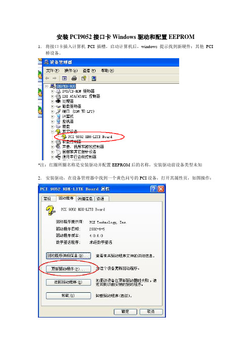
安装PCI9052接口卡Windows驱动和配置EEPROM
1.将接口卡插入计算机PCI插槽,启动计算机后,windows 提示找到新硬件:其他PCI 桥设备。
*注:红圈所圈名称是安装驱动并配置EEPROM后的名称,安装驱动前设备类型未知
2.安装驱动,在设备管理器中找到一个黄色问号的PCI设备,打开其属性页,如图操作:
点击“浏览”按钮选择PCI9052驱动所在文件夹该文件夹含有以下文件:
按“下一步”安装驱动。
中途会提示该设备没有数字签名,选择“仍然继续”,继续安装。
4.安装驱动后,使用PlxMon.exe配置EEPROM
点击图中所圈按钮,
从“Load File”载入文件s0_8reg.eep
点击“Write”按钮,然后关闭对话框
3.重启计算机,可能提示需要重新安装驱动,重新安装驱动即可。
Lenovo G470驱动安装说明(windows XP )
Lenovo G470驱动安装说明(windows XP )注意事项:1.在安装windows XP之前,需要在BIOS中将硬盘改为兼容模式,否则在安装系统时会提升找不到硬盘或蓝屏。
2.修改方法为:开机屏幕上出现Lenovo标志时按F2进入BIOS-->Advanced-->SATA Mode Selection,把AHCI改为IDE后按F10保存退出即可。
驱动安装步骤:1.主板芯片组驱动安装Lenovo G470主板芯片组驱动(设备管理器中显示为:SM 总线控制器)安装。
双击“G470_XP_Chipset.exe”文件安装,按安装中出现的默认提示项操作。
2.英特尔管理引擎驱动程序安装Lenovo G470英特尔管理引擎驱动程序(设备管理器中显示为:PCI简易通讯控制器)安装。
双击“G470_XP_ME.exe”文件安装,按安装中出现的默认提示项操作。
3.显卡驱动安装Lenovo G470显卡驱动程序(设备管理器中显示为:视频控制器)安装双击“ G470_XP_VGA_ATI.exe”或者“G470_XP_VGA_Intel.exe”文件安装,按安装中出现的默认提示项操作。
注意事项:由于该机型有HDMI接口,需要先安装声卡驱动,再安装显卡驱动,否则设备管理器中会有“Audio Device on High Definition Audio bus”黄色问号。
4.声卡驱动安装Lenovo G470声卡驱动程序(设备管理器中显示为:High Definition Audio 总线上的音频设备)安装。
双击“ G470_XP_Audio.exe”文件安装,按安装中出现的默认提示项操作。
注意事项:如果使用XP SP2系统,设备管理器中会显示PCI DEVICE黄色问号,需要先安装KB888111声卡补丁,再安装“G470_XP_Audio.exe”文件如果使用XP SP3系统直接安装“G470_XP_Audio.exe ”即可。
Lenovo G470驱动安装说明(windows 7 32bit )
Lenovo G470驱动安装说明(windows 7 32bit )驱动安装前准备:1.请提前下载所需的驱动程序安装文件,并打开存放驱动文件的目录,以下操作都以驱动文件存放的目录为准介绍。
2.下载的驱动安装文件均为自解压文件,并包含自动安装参数,请以操作系统管理员身份双击执行文件即可,对于安装过程中可能出现的选择提示,按照系统提示的默认项操作,以便完成驱动安装。
部分补丁包需要手动安装。
驱动安装步骤:1.主板芯片组驱动安装Lenovo G470主板芯片组驱动(设备管理器中显示为:SM总线控制器)安装。
双击“Chipset.exe”文件安装,按安装中出现的默认提示项操作。
2.英特尔管理引擎驱动程序安装Lenovo G470英特尔管理引擎驱动程序(设备管理器中显示为:PCI简易通讯控制器)安装。
双击“G470_Win7_MEI.exe”文件安装,按安装中出现的默认提示项操作。
3.显卡驱动安装Lenovo G470显卡驱动程序(设备管理器中显示为:标准VGA图形适配器)安装注意:此机型分带双显卡切换和不带双显卡切换两种型号。
带双显卡切换:分别双击“G470_Intel_VGA_32.exe”和“G470_Win7_ATI_Muxless.exe”不带双显卡切换:双击“G470_Win7_ATI_XT.exe”按安装中出现的默认提示项操作。
4.声卡驱动安装Lenovo G470声卡驱动程序安装。
双击“G470_Win7_Audio.exe”文件安装,按安装中出现的默认提示项操作。
5.网卡驱动安装Lenovo G470网卡驱动(设备管理器中显示为:以太网控制器)安装。
双击“G470_Win7_LAN.exe”文件安装,按安装中出现的默认提示项操作。
6.无线网卡驱动安装Lenovo G470无线网卡驱动(设备管理器中显示为:网络控制器)安装。
双击“ G470_Win7_WLAN.exe”文件安装,按安装中出现的默认提示项操作。
安装和配置PCIPCIExpress与PXIPXIExpressDAQ设备
安装和配置PCIPCIExpress与PXIPXIExpressDAQ设备本节内容包含事前准备DAQ系统概述组装PCI/PCI Express和PXI/PXI Express DAQ硬件PCI/PCI Express DAQ硬件PXI/PXI Express DAQ硬件SC Express硬件线缆和附件为NI即插式DAQ设备配置NI-DAQmx事前准备返回页首本文主要介绍安装和配置PCI/PCI Express及PXI/PXI Express DAQ设备的详细步骤。
开始前,请确保已安装应用开发环境和NI-DAQmx驱动软件。
详细信息,请参阅安装LabVIEW和NI-DAQmx。
DAQ系统概述返回页首图1是一个典型的DAQ系统,由以下部分组成:传感器、信号调理装置、连接设备与附件的线缆、DAQ设备、应用程序开发软件和计算机。
下文中的各节涵盖了一个常规DAQ系统的安装流程。
图1. 常规DAQ系统的组成部分组装PCI/PCI Express和PXI/PXI Express DAQ硬件返回页首PCI/PCI Express和PXI/PXI Express DAQ硬件产品品种多样,既有低价位、多功能的PCI/PCIExpress板卡,也有高性能、带信号调理功能的PXI/PXI Express模块。
图2. PCI/PXI M系列和PCI Express/PXI Express X系列PCI/PCI Express DAQ硬件返回页首请按照下列步骤,安装PCI/PCI Express DAQ板卡:1. 关闭计算机并拔下插头。
2. 打开计算机机箱盖和/或扩展槽盖。
3. 触摸计算机的金属部分,以释放静电。
图3. 安装PCI/PCI Express板卡:(1) PCI/PCI Express板卡;(2) PCI/PCI Express系统插槽;(3)带PCI/PCI Express插槽的计算机4. 将板卡插入可用的PCI/PCI Express系统插槽。
Win7系统安装不了PCI简易通讯控制器出现黄色感叹号如何解决
Win7系统安装不了PCI简易通讯控制器出现黄色感叹号如何
解决
有不少win7 64位系统用户在安装PCI简易通讯控制器的时候发现安装不了,打开设备管理器的时候发现在其他设备下的PCI简易通讯控制器有一个黄色感叹号,这是怎么回事呢,现在为大家讲解一下Win7系统安装不了PCI简易通讯控制器出现黄色感叹号的具体解决方法。
解决方法
1、打开设备管理器,右键点击“PCI简易通讯控制器”,在下拉菜单中点击属性;
2、在打开的“PCI简易通讯控制器属性”窗口显示:该设备的驱动程序未被安装,我们点击更新驱动程序;
3、在新窗口中,我们鼠标左键点击:浏览计算机以查找驱动程序软件;
4、我们在下一个更新驱动程序软件-PCI简易通讯控制器窗口点击:从计算机的设备驱动程序列表中选择,再点击:下一步;
5、在接下来的更新驱动程序软件-PCI简易通讯控制器窗口点击:系统设备,再点击:下一步(N);
6、接下来,我们左键点击框中厂商栏中的(标准系统设备)(注意:一定要是红线划定的标准系统设备,另一个不行!),再点击:下一步(N);
7、这时会弹出一个:更新驱动程序警告窗口,我们别管它,点击是就行了;
8、这时会出现:Windows已经成功地更新驱动程序文件,我们点击关闭;
9、这时我们回到设备管理器的窗口中,再次查看其他设备下的PCI简易通讯控制器,会发现黄色感叹号已经没了,对此我们也就解决了PCI简易通讯控制器有黄色感叹号的问题。
上面给大家介绍的就是关于Win7系统安装不了PCI简易通讯控
制器出现黄色感叹号如何解决的全部内容,有碰到这样情况的用户们可以按照上面的方法解决即可。
打开设备管理器发现里面有未知设备的解决方法
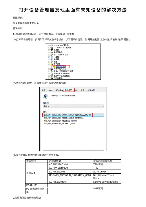
打开设备管理器发现⾥⾯有未知设备的解决⽅法
故障现象:
设备管理器中有未知设备
解决⽅案:
1. 通过获取硬件ID ⽅法,进⾏对⽐确认,进⾏驱动下载安装
(1) 打开设备管理器,找到如下标识黄⾊叹号设备,以下图举例说明,在“⽹络控制器”上点击⿏标“右键”选择“属性
”; (2) 找到“详细信息”,在属性选项中选择“硬件ID”选项
;
(3)请下载官⽹提供的对应驱动进⾏相关下载。
设备名称对应硬件ID
设备对应驱动名称未知设备ACPI\PNP0C31\1
TPM 驱动ACPI\WEC1000\1
TPM ACPI\LBA0001
ACPI Driver USB\VID_1926&PID_1843&REV_0008
NextWindow Touch Driver ACPI\LBAI0100\1
Lenovo Service Engine PCI 串⾏⼝
AMT 驱动PCI 简易通信控制
器
2.使⽤乐驱动⾃动安装驱动
(1)通过下载乐驱动,安装相关的驱动。
点击“使⽤⼯具⾃动安装驱动”;
(2)点击“免费下载”,下载乐驱动进⾏安装;
(3)驱动会⾃动检测,找到对应驱动,选择对应驱动进⾏安装即可。
- 1、下载文档前请自行甄别文档内容的完整性,平台不提供额外的编辑、内容补充、找答案等附加服务。
- 2、"仅部分预览"的文档,不可在线预览部分如存在完整性等问题,可反馈申请退款(可完整预览的文档不适用该条件!)。
- 3、如文档侵犯您的权益,请联系客服反馈,我们会尽快为您处理(人工客服工作时间:9:00-18:30)。
关于PCI简易通讯控制器和Turbo驱动的安装方法
答:
Intel 5系列芯片组机型在设备管理器里出现“PCI简易通讯控制器”或者Intel(R) Turbo Boost Technology Driver上出现打叹号或打问号:
首先要查看设备范例ID :
在“我的电脑”上点击右键,选择“属性”,选择“硬件”选项卡,选择“设备管理器”,在弹出窗口中找到带有黄色问号或是感叹号的设备,在该设备点击右键,选择“属性”,选择“详细信息”选项卡,查看“设备范例ID”所列出的值。
1、若设备范例ID 为VEN_8086 DEV_3B64
可下载,PCI简易通讯控制器XP、Windows7驱动:
ftp://fuwuzhan:fuwuzhan@/drivers/mei_intel_6001179.zip
2、若设备范例ID 为VEN_8086 DEV_3B32
在上面点击右键,手动更新驱动程序,从磁盘安装,指引到主板驱动ALL 目录的ibexiips.inf 文件
确定后,即可安装驱动。
