Mimics+3D+tools
mimics导出下颌骨方法

mimics导出下颌骨方法全文共四篇示例,供读者参考第一篇示例:mimics软件是一款功能强大的三维图像处理软件,广泛应用于医学影像处理、生物力学研究、数字化建模等领域。
在医学领域中,mimics软件可以用于解剖结构的三维重建,手术模拟、假体设计等方面,为医生提供了强大的工具支持。
下颌骨是人体中的一个重要解剖结构,它由下颌骨体和下颌角组成,是咀嚼、发音等功能的关键。
下颌骨的形态特征对于口腔修复、口腔颌面外科等领域的临床治疗具有重要意义。
在进行下颌骨研究和临床治疗时,需要进行下颌骨的三维重建和分析。
mimics软件提供了丰富的工具和功能,可以帮助用户实现下颌骨的三维重建和分析。
下面我们将介绍一下利用mimics软件导出下颌骨的方法。
要进行下颌骨的三维重建,需要准备好下颌骨的医学影像数据,一般可以是CT或MRI扫描图像。
在mimics软件中,点击“文件”-“导入”来导入下颌骨的影像数据,然后选择相应的文件进行导入。
导入完成后,可以在“3D图像”界面看到下颌骨的三维模型。
接下来,点击“分割”工具,选择“手动分割”或“自动分割”来对下颌骨进行分割。
手动分割需要用户手动标记下颌骨的轮廓,而自动分割则是根据软件算法来进行自动分割。
分割完成后,可以对下颌骨的三维模型进行编辑和修复。
可以使用“平滑”、“填充洞”等工具来对模型进行修复,使其更加完整和平滑。
还可以对下颌骨的表面进行细节处理,如去除多余的结构、调整骨面的平滑度等。
完成上述步骤后,就可以对下颌骨的三维模型进行进一步分析和编辑。
可以使用“测量”工具来测量下颌骨的各项参数,如长度、角度等,也可以使用“分析”工具来分析下颌骨的形态特征,如凹凸、骨密度等。
通过点击“文件”-“导出”来导出下颌骨的三维模型。
可以选择不同的文件格式进行导出,如STL、OBJ等,以便于后续的应用。
导出完成后,就可以将下颌骨的三维模型应用到口腔修复、口腔颌面外科等临床治疗中。
利用mimics软件导出下颌骨的方法并不复杂,只需要按照上述步骤进行操作即可。
Mimics中文培训手册

M i m i c s中文培训手册 Prepared on 24 November 2020Mimics Innovation Suite 基于解剖学的工程学Mimics 培训手册/ 公告这本培训手册是为了帮助用户顺利地开始Mimics软件的使用而编写的,并不能够代替Mimics用户手册,也不能代替Materialise公司提供的培训。
这本培训手册在不同的练习中使用了Mimics全部的模块,如果没有相关模块的使用权无法完成练习。
请注意: 这本培训手册的使用以熟悉Windows系统操作技能为前提。
听而易忘见而易记做而易懂孔子 2011 MaterialiseMimics, Materialise, and any and all Materialise brand, product, service and feature names, logos and slogans mentioned in this document are registered trademarks and/or trade names of Materialise and are protected by trademark laws in the United States or other countries. All other brand, product, service and feature names or trademarks are the property of their respective owners. No user has any right, title, or interest in those marks or names not previously expressly granted in writing to such user by Materialise.1 / 目录Materialise China – Room1803, , DongfangRoad –Shanghai –........................................................................................................................................................................................................................................................................................................................................................... /.............................................................................................................................................................................................................................................................................................................................................................................................................................................................................................................................................................. /........................................................................................................................................................................................................................................................................................................................................................................................................................................................................................................................................................................................................................................................................................................................................................................................................................................... /....................................................................................................................................................................................................................................................................................................................................................................... /................................................................................................................................................................................................................................................................................................................................................................................................................................................................................................................................................................................................................................................................................................................................................................................................................................................................................................................................................................................. /................................................................... /........................................................................................................................... Materialise China – Room1803, , DongfangRoad –Shanghai –/ Mimics简介Mimics 是一个连接二维图像数据(CT, MRI, 工业扫描数据...)和三维工程学应用的图像处理工具。
Mimics软件三维重建在临床骨科疾病中的应用
Mimics软件三维重建在临床骨科疾病中的应用The Application of Mimics Software in 3D Reconstruction ofClinical Orthopedic Diseases刘永(河南中医药大学,河南郑州,450000)中图分类号:R274文献标识码:A文章编号:1674-7860(2020)09-0121-04【摘要】Mimics软件是一款能够处理医学影像信息的多功能、可视化、实用性软件。
此软件能够对二维医学影像信息进行数字化三维重建,将人体不同组织器官区别开并展现出来,进而定量、定性、个体化分析感兴趣的研究目标。
其三维重建功能能满足临床骨科需要,目前该软件已在临床骨科有着丰富的实践。
本文结合该领域研究进展,首先介绍了该软件内含的五大模块:STL+模块、RP Slice 模块、MedCAD 模块、Simulation 模块、FEA模块。
五大模块可进行不同组合或为其他后处理软件的接口。
交互式医学图像控制系统(Materialise's Interactive Medical Image Control System,Mimics)软件不仅是沟通二维到三维的桥梁,同时也是联系临床兴趣目标与后续研究的纽带。
其次介绍了三维重建思路分析过程,包括导入医学影像信息、提取轮廓、区域增长、生成三维模型,这是从影像资料到建成模型的基本操作。
接着从骨科教学、疾病诊断、数据测量、骨组织力学分析、3D模型打印、修复体设计、术前模拟等7个方面加以综述,介绍了此软件在临床骨科的丰富实践,为临床骨科医师提供参考。
最后对Mimics软件的应用前景进行展望,相信随着社会的不断进步,Mimics软件在临床骨科疾病中发展空间会越来越广阔。
【关键词】Mimics软件;三维重建;临床骨科【Abstract】Mimics software is a multi-functional,visual and practical software that can process medical image information.This software can conduct digital three-dimensional reconstruction of two-dimensional medical image information, distinguish and display different tissues and organs of the human body,and then conduct quantitative,qualitative and individualized analysis of research objectives of interest.Its 3D reconstruction function can meet the needs of clinical orthopedics.At present,this software has rich practice in clinical bined with the research progress in this field,this paper firstly introduces five modules of the software:STL+ module,RP Slice module,MedCAD module,Simulation module and FEA module.Five modules can be different combinations or other post-processing software interface.Mimics software is not only a bridge from 2D to 3D, but also a link between clinical interest goals and follow-up studies.Secondly,it introduces the analysis process of 3D reconstruction ideas,including importing medical image information, extracting contour, regional growth and generating 3D model, which is the basic operation from image data to model building.Then,this paper reviews the teaching of orthopedics,disease diagnosis,data measurement,bone tissue mechanics analysis,3D model printing,prosthesis design,preoperative simulation and other 7 aspects,introduces the rich practice of this software in clinical orthopedics,and provides a reference for clinical orthopedics physicians.Finally,the application prospect of Mimics software was prospected.It is believed that with the continuous progress of society,the development space of Mimics software in clinical orthopaedic diseases will be more and more broad.【Keywords】Mimics software;3D reconstruction;Clinical orthopaedicsdoi:10.3969/j.issn.1674-7860.2020.09.049交互式医学图像控制系统(Materialise's Interactive Medical Image Control System,Mimics)是一款由欧洲比利时Materialise 公司研发的能够处理医学影像信息的多功能、可视化、实用性软件。
mimics中文教程

4 simulation module 仿真模块 手术模拟仿真模块是一个开放的平台。您可以进行详细的分析您的人体测量分析,计划
截骨术和分心手术或模拟,来解释你的一种外科手术植入方案. 人体测量学分析
要进行人体测量分析,先选取一个模版,预先设定所需的标记 、参照面及测量方式,平 面及测量方式所需的标记点被确定之后,平面及测量方式也就被确定下来,如果没有合适的 模版,也可以自定义模版。
导入模块用来从大量的扫描式中导入 CT 和 MRI 数据,可提供的源数据可以是 CD, 光盘,DAT 带,以磁带等。
1 RP Slice Module RP 切片模块 RP(快速成型)切片模块通过切片文件建立起了 Mimics 和其它快速成型系统的接口 RP
切片模块能够自动的生成产生 RP 模型必要的支撑结构。
3.1 通过轮廓线拟合 CAD 对象 在分割功能状态下,Mimics 自动在分离出的掩模上生成轮廓线,MEDCAD 能在给
定误差的条件下自动生成一个局部轮廓线模型,进而用于医用几何学 CAD 模型中。
3.2 交互式或者参数化创建 CAD 物体 可在 2D 或 3D 视图中直接创建 CAD 对象,或者用参数设置的方式创建(如定义
分割 这一功能可将一个对象分成彼此独立的 3D 模型,然后建立多个不同的局部 3D 模型。 融合 融合功能将所选的不同模型变成一个模型。 镜像 镜像功能可以将选定的对象沿一个设定的平面或一个巳有平面(从人体数据分析或 MEDCAD 得来)镜像生成新的对象,可以选取多个对象进行镜像操作。 重定位 对象可以被转化或者旋转。对每种操作,对象都能被调整到客户需要的合适大小 和位置。客户可以选择相应的对象操作限制。可以选择的有:轴向移动,平面移动,绕轴旋 转和绕点旋转。当然,无限制操作也是可选项之一。通过配准功能 ,客户可以利用标志点简 单的重定位对象。也可以利用鼠标定位对象。 5 FEA Module 有限元分析模块
mimics教程
mimics教程第一单元什么是MimicsMimics是Materialise公司的交互式的医学影像控制系统,即为Materiaise's interactive medical image control system.它是模块化结构的软件,可以根据用户的不用需求有不同的搭配。
下面是这些模块的介绍:MIMICS软件介绍MIMICS是一套高度整合而且易用的3D图像生成及编辑处理软件,它能输入各种扫描的数据(CT、MRI),建立3D模型进行编辑,然后输出通用的CAD(计算机辅助设计)、FEA(有限元分析),RP(快速成型)格式,可以在PC机上进行大规模数据的转换处理。
MEDCAD模块:MEDCAD模块是医学影像数据与CAD之间的桥梁,通过双向交互模式进行沟通,实现扫描数据与CAD数据的相互转换。
在MIMICS的项目中建立CAD项目的方法有以下两种:1. 轮廓线建模:在分割功能状态下,MIMICS自动在分离出的掩模上生成轮廓线,MEDCAD能在给定误差的条件下自动生成一个局部轮廓线模型,进而用于医用几何学CAD模型中。
创建的CAD模型的可能方法:-B样条曲线及曲面-点,线,圆,曲面,球体,圆柱体等所有这些实体均可以iges格式输出到CAD软件中制做植入体,另一个典型的运用是用MEDCAD模块做统计分析,如测量很多不同股骨头的数据,为建立标准股骨头植入体时作参考。
2. 参数化或交互式CAD建模可在2D或3D视图中直接创建CAD对象,或者用参数设置的方式创建(如定义圆心、半径来创建一个圆),创建后可用鼠标进行交互式编辑。
方便设计验证:为验证CAD植入体的设计,MIMICS输入STL文件格式在2D视图及标准视图中显示,或在3D视图中显示,用透明方式显示解剖关系,使用这一方法可以快速实现医学影像数据在CAD设计软件中的调用。
RP-SLICE模块:Rp-slice模块在MIMICS与多数RP机器之间建立SLICE格式的接口,RP-Slice 模块能自动生成RP模型所需的支撑结构。
mimics教程
mimics教程第一单元什么是MimicsMimics是Materialise公司的交互式的医学影像控制系统,即为Materiaise's interactive medical image control system.它是模块化结构的软件,可以根据用户的不用需求有不同的搭配。
下面是这些模块的介绍:MIMICS软件介绍MIMICS是一套高度整合而且易用的3D图像生成及编辑处理软件,它能输入各种扫描的数据(CT、MRI),建立3D模型进行编辑,然后输出通用的CAD(计算机辅助设计)、FEA(有限元分析),RP(快速成型)格式,可以在PC机上进行大规模数据的转换处理。
MEDCAD模块:MEDCAD模块是医学影像数据与CAD之间的桥梁,通过双向交互模式进行沟通,实现扫描数据与CAD 数据的相互转换。
在MIMICS的项目中建立CAD项目的方法有以下两种:1. 轮廓线建模:在分割功能状态下,MIMICS自动在分离出的掩模上生成轮廓线,MEDCAD能在给定误差的条件下自动生成一个局部轮廓线模型,进而用于医用几何学CAD模型中。
创建的CAD模型的可能方法:-B样条曲线及曲面-点,线,圆,曲面,球体,圆柱体等所有这些实体均可以iges格式输出到CAD软件中制做植入体,另一个典型的运用是用MEDCAD模块做统计分析,如测量很多不同股骨头的数据,为建立标准股骨头植入体时作参考。
2. 参数化或交互式CAD建模可在2D或3D视图中直接创建CAD对象,或者用参数设置的方式创建(如定义圆心、半径来创建一个圆),创建后可用鼠标进行交互式编辑。
方便设计验证:为验证CAD植入体的设计,MIMICS输入STL文件格式在2D视图及标准视图中显示,或在3D视图中显示,用透明方式显示解剖关系,使用这一方法可以快速实现医学影像数据在CAD设计软件中的调用。
RP-SLICE模块:Rp-slice模块在MIMICS与多数RP机器之间建立SLICE格式的接口,RP-Slice 模块能自动生成RP模型所需的支撑结构。
Mimics软件介绍
来源:CTA
应用举例 主动脉瓣植入测试 医师沟通
干预规划
3D 打印模型特征 心脏组织用柔性材料打印,而钙化物用半刚性材料打印 可视化心室切口 可见主要乳头肌,二尖瓣口和升主动脉病变 心室肌小梁消除
主动脉瓣用刚性材料打印
患者与扫描信息 女性,73 岁,白种人 病理:严重的主动脉瓣与二尖瓣狭窄、心室肥大
来源:CTA 应用举例 干预规划 解剖教育 外科手术干预培训 3D 打印模型特征 心脏组织用柔性材料打印,而钙化物用半刚性材料打印 左心房和右心敞开- 实现可视化 可见心室肌小梁和主要的乳头状肌 可见二尖瓣和主动脉瓣口及升主动脉
案例 2:附有心肌的完整心脏
2、心脏打印的教育和培训 在培训客户或教育学生时,没有什么比实践经验更宝贵了。把尸体成本省下来,改用患者特 异医学模型吧!高级培训让您与众不同!
案例 1:先天性心脏病模型
患者与扫描信息 男性,婴儿,白种人 病理:右室双出口、心房间隔缺损、室间隔缺损 来源:CTA 应用举例 干预规划 解剖教育 外科手术干预培训 3D 打印模型特征 心脏组织和主动脉用柔性材料打印 有内腔和主动脉弓 专利导管 可视化心室切口 案例 2:主动脉瓣和二尖瓣钙化导致的肥厚性心脏模型
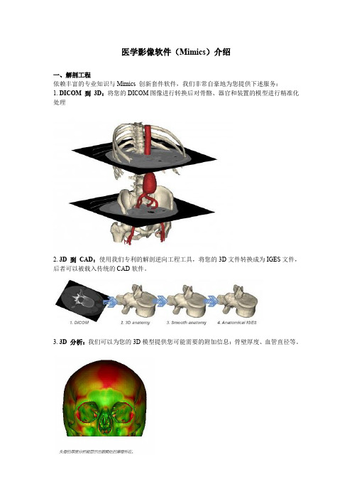
医学影像软件(Mimics)介绍
一、解剖工程 依赖丰富的专业知识与 Mimics 创新套件软件,我们非常自豪地为您提供下述服务: 1. DICOM 到 3D:将您的 DICOM 图像进行转换后对骨骼、器官和装置的模型进行精准化 处理
2. 3D 到 CAD:使用我们专利的解剖逆向工程工具,将您的 3D 文件转换成为 IGES 文件, 后者可以被载入传统的 CAD 软件。
MIMICS系统三维重建指引下经皮穿刺引流术对重症胰腺炎穿刺操作时间、成功率影响
·103CHINESE JOURNAL OF CT AND MRI, NOV. 2023, Vol.21, No.11 Total No.169【通讯作者】张爱民,男,副主任医师,主要研究方向:多发伤,创伤骨科数字化微创治疗。
E-mail:****************Percutaneous Puncture and中国CT和MRI杂志 2023年11月 第21卷 第11期 总第169期频率2~5MHz。
患者平卧,显露腹部,常规行腹部超声检查明确积液位置,选择距腹壁最近、位置相对较低、积液较多部位进行穿刺,穿刺点采用1%利多卡因局麻,超声引导下穿刺,注意避开大血管,回抽有炎性坏死液体后置入引流管,抽出积液、坏死组织后采用生理盐水清洗,固定引流管进行引流。
(2)研究组采用MIMICS三维重建指引下PCD治疗,穿刺前行腹部CT检查,仪器为Brilliance 64排螺旋CT机(荷兰飞利浦),明确坏死组织位置及范围、积液位置等,将扫描数据导入MIMICS,完成穿刺路径规划和安全性评估。
根据制定的方案在患者皮肤上通过定位装置进行定位标记,根据定位标记显示的数据联合床旁超声实时导航进行腹腔穿刺。
穿刺引流操作与对照组相同。
两组PCD后均每日观察引流液状况,引流液送细菌培养。
1.3 观察指标 (1)两组穿刺情况,包括穿刺前影像学重复确认次数、穿刺操作时间、穿刺成功率、平均穿刺次数,穿刺后行腹部CT检查,观察穿刺引流管是否进入预定引流区域,进入预定引流区域则判定为穿刺成功,穿刺成功率=穿刺成功例数/总例数×100%。
(2)两组治疗前、治疗后1d、3d、7d血清炎性因子[C反应蛋白(CRP)、淀粉样蛋白A(SAA)、降钙素原(PCT)],采集患者治疗前、治疗后1d、3d、7d血液标本5mL,离心处理取血清,采用酶联免疫吸附法测定上述指标水平。
(3)两组治疗前、治疗后1d、3d、7d血清前列环素I2(PGI2)、血栓素2(TXA2),与血清炎性因子同时检测,检测方法为酶联免疫吸附法。
- 1、下载文档前请自行甄别文档内容的完整性,平台不提供额外的编辑、内容补充、找答案等附加服务。
- 2、"仅部分预览"的文档,不可在线预览部分如存在完整性等问题,可反馈申请退款(可完整预览的文档不适用该条件!)。
- 3、如文档侵犯您的权益,请联系客服反馈,我们会尽快为您处理(人工客服工作时间:9:00-18:30)。
General information on the operation of 3D ToolbarThe 3D toolbar is displayed at the right side of the 3D view.Toggle transparencyYou can show the 3D object opaque or transparent. Click on the button in the 3D toolbar to toggle between opaque and transparent view.You can change the transparency of the 3D object and make objects transparent. Drag the Transparency slider at the bottom of the 3D properties dialog. If the slider is all the way to the right, the 3D surface is opaque and nothing below the surface can be visualized. If the slider is all the way to the left, the 3D surface is completely transparent.ClippingClipping allows you to visualize the section in which you are interested. It can be used, to evaluate the gray values on the section boundaries or to look inside the model to get a better comprehension of the geometry. The section can be made along the different planes, axial, coronal and sagittal. Several clipping planes can be activated at the same enabling you to isolate thepart of interest.To enable clipping click on the Enable/Disable clipping button . The settings of the clipping can be changed in the clipping tab:ActiveBy default one axial clipping plane is active. To make more planes active, make sure to check the active iconThe position of the clipped plane in the 3D view corresponds with the position of the active axial, sagittal or coronal image. Scrolling through the 2D images updates the clipped plane in 3D. Alsonavigation on the clipped 3D is possible by clicking on visible parts on the 3D. When you rotate the 3D along the clipped plane, the visibility automatically reverses.TypeAs stated above you can select multiple clipping planes. For each view you can define two clipping planes. For each of the clipping planes, you can choose which objects need to be clipped. You can choose this by selecting the clipping plane in the list and changing the selections in the dropdown menu . All objects are selected by default.ClipBy default the direction of the clipping plane is defined by the viewing angle. The direction of the clipping plane can be locked by selecting a clip direction. Click on the clip icon to lock to a clipping direction or to unlock.LockThe location of the clipping plane is locked to the slice position. To unlock the clipping plane from the slice position, disable the lock icon . When the lock icon is disabled, you can determine the location of the clipping plane with the slider at the bottom of the clipping tab.TexturingYou can also choose between three texturing methods:When choosing No texturing, only the 3D Object is clipped and you can see inside the 3D Object. When choosing Object Texturing, a texture corresponding with the 2D slice is placed in the contours of the 3D Objects. When choosing Full slice texturing, the 3D Object is not clipped, but the whole 2D slice is visible in the 3D window.Note: This technique is only available in OpenGL and direct3D rendering (not in software). To check your rendering option, go to Option | Preferences and select the OpenGL or Direct3D rendering option in the 3D settings. To accelerate the performance of clipping, activate the hardware acceleration in the same dialog.Volume renderingVolume rendering allows you to quickly visualise your 2D image data as a 3D object without any segmentation. The 3D object is build up out of the voxels representing the dataset. The transparency of the voxels is determined based on their grey value.Volume rendering is a pure visualisation tool and cannot be used for anything else (e.g. exporting). You can find the interface for the volume rendering in the volume rendering project management tab:Defining the opacityThis interface shows a histogram which represents the gray values or Hounsfield units of the dataset. The transparency of the gray values is set by the opacity lines on the histogram. The higher a line is positioned the more opaque the voxels within that range will be visualised. In the first column the line representing the low Hounsfield values is positioned to the bottom. Subsequently the voxels are represented transparent. In the second column the line is positioned higher which makes the voxels opaque.Move a point Position a point click left and drag the point to its new positionAdd a point Click left on a line to add an extra pointDelete a point Right click on a point and select delete to delete a point Defining the colorThe graph below the histogram defines the color of the rendered voxels. You can choose a color for each point in the graph by right-clicking on the points and choosing Change Color. Mimics will then create an interpolated shading between the different control points. The same system for adding, moving and deleting bullets is available as for the opacity line.Predefined settingsOn the bottom of the volume rendering interface you find a dropdown list with predefined settings. The predefined settings are optimized for CT image and allow you to quickly select bone,soft-tissue or both.You can save your current setting as a predefined setting by clicking on the save button. To delete your predefined setting, select it from the dropdown box and click on the delete button.Show reference planesIt is possible to show in the 3D view the reference planes of the current position by clicking on the Show Reference Plane button . The reference planes take over the colors that belong to the different views:Axial RedCoronal OrangeSagittal GreenCross Sectional BlueParallel YellowThe reference planes that have to be shown can be selected in the 3D tab of the Preference settings. Only the reference planes of the views that are displayed can be shown in the 3D view.Select 3D viewWhen you click on Select 3D View button , a list with all possible default views is displayed. Selecting an item from this list will position the 3D object according to the selected position.Rotate viewThe rotate function is only available on a 3D object. There are different ways to select the rotate function:•right-drag with your mouse button•use the arrows-keys for precise rotation•use Home / End to rotate 10 degrees Left / Right•use Page Up / Page Down to rotate 10 degrees Up / Down•right-click in the 3D view and select Rotate View from the context menu•click on the Rotate View button in the toolbar•select View > Rotate View from the menu barToggle visibilityBy toggling the colored cubes in the 3D toolbar, you can make the 3D objects, with the corresponding color, visible or invisible. For every 3D object in the project there is a corresponding cube.。