Testing General Relativity with Atom Interferometry
原子干涉仪相对论效应的理论分析
原子干涉仪相对论效应的理论分析刘琳霞;董蕴华【摘要】利用高灵敏度的原子干涉仪开展广义相对论效应的实验研究,需要考虑各种相对论效应对原子干涉的影响.结合量子力学与广义相对论,分析了原子干涉仪中的广义相对论效应,以及相对论效应中的引磁效应.初步分析计算结果表明,在牛顿力学框架下,地球自转引起原子的科里奥利加速度的量级为~10-4g,其相对论修正,即引磁效应的量级约为~10-13g.【期刊名称】《河南机电高等专科学校学报》【年(卷),期】2017(025)005【总页数】4页(P1-4)【关键词】原子干涉仪;相对论效应;原子波【作者】刘琳霞;董蕴华【作者单位】河南工学院,河南新乡453003;河南工学院,河南新乡453003【正文语种】中文【中图分类】O412原子干涉仪的工作原理类似于光学干涉仪,它是利用物质波的特性来实现干涉的。
但物质波的原子运动速度远小于光速,其相干性较好,因此,原子干涉仪比光学干涉仪的灵敏度更高。
由于其高灵敏度性,原子干涉仪在精密测量领域有广泛的应用,如牛顿引力常数、重力加速度与转动、导航定位等方面[1]。
高精度的原子干涉仪也用来开展广义相对论效应的实验检验,包括等效原理的实验检验、引力波的探测等[2]。
对于检验广义相对论效应的实验,需要考虑各种广义相对论效应对原子干涉的影响。
目前,虽然已有不少文献分析和讨论了原子干涉仪中的广义相对论效应,但这些工作只关注某些特定的相对论效应[3]。
在本文中,我们介绍了原子干涉仪广义相对论效应及其研究方法,并结合量子力学与广义相对论,初步分析了广义相对论中的引磁效应对原子干涉的影响。
对于原子干涉中广义相对论效应的研究,早期的研究者有Varju小组[4],主要是为解释原子或中子干涉仪中的相对论效应。
但是,要想全面分析原子干涉仪中与自旋相关的相对论效应,需要考虑实验过程中激光与原子自旋的耦合效应。
Wajima 和 Anandan等人分析了量子干涉仪中相对论的引力效应[5],主要是用来估算中子干涉仪中由地球引力场的相对论修正部分带来的干涉相移。
英文版原子物理课件
1.1 Introduction
The origins of atomic physics :quantum mechanics Bohr model of the H This introductory chapter surveys some of the early ideas: Spectrum of atomic H and Bohr Theory Einstein's treatment of interaction of atom with light the Zeeman effect Rutherford scattering And so on
Shanxi University Atomic Physics
1.2 Spectrum of atomic hydrogen_3
Wavenumbers may seem rather old-fashioned but they are very useful in atomic physics
the characteristic spectrum for atoms is composed of discrete lines that are the ‘fingerprint' of the element.
In 1888, the Swedish professor J. Rydberg found that the spectral lines in hydrogen obey the following mathematical formula:
Shanxi University Atomic Physics
Lyman series: n’ = 2; 3; 4; … n = 1. Balmer (n = 2), Paschen series: (n = 3), Brackett (n = 4) and Pfund (n = 5)
GasAlertMicro 5 系列便携式气体检测仪器说明书

VOCs, CO 2, LEL, H 2S, CO, O 2, SO 2, PH 3, NH 3, NO 2, HCN, Cl 2, ClO 2, O 3Protect yourselfCompact and lightweight, GasAlertMicro 5 Series instruments areavailable in diffusion or pumped instruments. The portable gas detectors simultaneously monitors and displays up to five potential atmospheric hazards. The GasAlertMicro 5 PID model also identifies PID detectable VOCs, while the GasAlertMicro 5 IR uses an NDIR sensor to monitorCO 2 levels. Adaptable to a variety of applications, GasAlertMicro 5 Series instruments have an extensive selection of user-settable field options. Use the passcode function to prevent unauthorized modifications of the instrument’s settings. Compatible with BW’s MicroDock II automatic test and calibration system, GasAlertMicro 5 Series instruments are unparalleled in their versatility, performance and overall value.Standard Package Contents• D etector complete with specified sensor(s), stainless steel alligator clip and concussion-proof housing• Rechargeable battery pack or alkaline pack with three AA batteries • Cradle charger and wall outlet charging adaptor (with rechargeable battery option)• Sample probe (with motorized pump option)• Screwdriver• Calibration/test adaptor and hose • Manual• Multi-language CD manual General SpecificationsSize 5.7 x 2.9 x 1.5 in. / 14.5 x 7.4 x 3.8 cm Weight 13.1 oz. / 370 gOperating temperature -4 to +122°F / -20 to +50°C14 to +104°F / -10 to +40°C (PID)Typical battery life 20 hours (15 hours PID/IR)**Based on a 5-gas instrument in diffusion mode at 68ºF / 20ºCCertifications and approvalsClass I, Div. 1, Gr. A, B, C, D American Bureau of Shipping (Toxic and PID models)ATEX: X g II 1 G Ga Ex ia IIC T4*X g II 2 G (IR model only)Ex d ia IIC T4*IECEx: Ga Ex ia IIC T4* Ex d ia IIC T4* (IR model only)*Temperature codes may vary as a function of the batteries installed. Please see owner’s manual for a complete listing of compatible batteries and codes.WarrantyFull two year warranty including sensors (one year Cl 2, NH 3, O 3, ClO 2 and PID sensor)5612-15GasAlertMicro 5.....................................................................................50GasAlertMicro 5 PID ..............................................................................52GasAlertMicro 5 IR ................................................................................54GasAlertMicro 5 Series Accessories, Spares & Replacements ............56GasAlertMicro 5 Series Service Parts (60)GasAlertMicro 5 DetectorOrder NumberGasAlertMicro 5 Region CodesNote: Listed above are commonly ordered instrument configurations. To create a custom GasAlertMicro 5 detector, use the configurator table on the next page or contact BW Technologies for a copy of the electronic order number configurator.GasAlertMicro 5Pump versionGasAlertMicro 5Diffusion versionOrder Number ConfiguratorOrder number:For example, the order number for a GasAlertMicro 5 configured for O 2, %LEL, Cl 2, H 2S and CO and equipped with a rechargeable battery pack and cradle charger, motorized sampling pump, yellow housing and North American powerconnectivity would be M5-XWCY-R-P-D-Y-N-00.*Note: Some gases (e.g. SO 2 and NH 3) cannot be combined in the same GasAlertMicro 5 configuration. Please checkwith Customer Service for specific availability.†Note: HCN can only be ordered in the Toxic 1 location when the Duo-Tox (CO/H 2S) sensor is ordered in theToxic 2 location. In all other configurations, HCN must be ordered in the Toxic 2 location.Note: Listed above are commonly ordered instrument configurations. To create a custom GasAlertMicro 5 PID detector, use the configurator table on the next page or contact BW Technologies for a copy of the electronic order number configurator.GasAlertMicro 5 PIDPump versionGasAlertMicro 5 PIDDiffusion versionOrder Number ConfiguratorOrder number:For example, the order number for a GasAlertMicro 5 PID configured for O 2, %LEL, VOCs, H 2S and CO and equipped with a rechargeable battery pack and cradle charger, motorized sampling pump, yellow housing and North Americanpower connectivity would be M5PID-XWQY-R-P-D-Y-N-00.*Note: Some gases cannot be combined in the same GasAlertMicro 5 configuration. Please check with CustomerService for specific availability.GasAlertMicro 5 IR DetectorOrder NumberGasAlertMicro 5 IR Region CodesNote: Listed above are commonly ordered instrument configurations. To create a custom GasAlertMicro 5 IR detector, use the configurator table on the next page or contact BW Technologies for a copy of the electronic order number configurator.Gas LegendGasAlertMicro 5 IRPump versionGasAlertMicro 5 IRDiffusion versionOrder number:For example, the order number for a GasAlertMicro 5 IR configured for O 2, %LEL, CO 2, H 2S and CO and equipped with a rechargeable battery pack and cradle charger, motorized sampling pump, yellow housing and North American powerconnectivity would be M5IR-XWBY-R-P-D-Y-N-00.*Note: Some gases cannot be combined in the same GasAlertMicro 5 configuration. Please check with CustomerService for specific availability.Order Number ConfiguratorDeluxe Confined Space KitM5-CK-DLConcussion-Proof BootGA-BM5-2For GasAlertMicro 5 Seriespumped unitsCarrying HolsterGA-HM5Fits securely on belt Confined Space Kits Order Number Carrying & Protective Accessories Order NumberConcussion-Proof BootGA-BM5-1For GasAlertMicro 5 Seriesdiffusion unitsSampling & Testing Equipment Order NumberNote: For complete list of Sampling & Testing Equipment, see the Sampling Equipment section.ReplacementTest Cap and HoseM5-TC-1Pump ModuleM5-PUMPReplacementDiffusion CoverM5-DC-1Manual Aspirator PumpGA-AS02For remote sampling; complete withprobe, hose and aspirator pumpAuxiliary Pump Filter withHose ConnectorM5-QCONN-K1Auxiliary Pump FilterM5-AF-K2 / M5-AF-K2-100Kit of 5 or 100, for legacyGeneration 1 pump modules onlyAuxiliary Pump FilterM5-AF-K3 / M5-AF-K3-100Kit of 5 or 100, for Generation 2pump modulesPower Accessories Order Number *Note: Battery packs and chargers should be used with the new version GasAlertMicro 5 Series gas detectors (red circuit boards).MicroDock IIOrder Number Cradle ChargerM5-C01Cradle charger for rechargeable battery packs(can charge battery pack with or without detector attached)Vehicle Adaptor 12 V dcGA-V-CHRG4Vehicle adaptor cable for use with cradle charger (M5-C01)Cradle Charger Kit with BatteryM5-C01-BAT08 / M5-C01-BAT08BComplete with charger and rechargeable battery packAlkaline Battery PackM5-BAT0501/M5-BAT0501B M5-BAT0502/M5-BAT0502BRechargeable Battery PackM5-BAT08/M5-BAT08B5062-26-NCL-EN59PID Cleaning KitM5PID-CLN-K1For PID sensorsReplacement Electrode StackM5PID-ES-1For PID sensorsReplacement 10.6 eV PID LampRL-PID10.6For PID sensorsReplacement Sensor Screens Order Number Replacement SensorsOrder Number Note: All sensors come with a 2 year warranty unless marked with an asterisk (*), denoting 1 year warranty.†Advisory: Detectors are equipped on a standard basis with SR-W04 combustible sensors. This sensor includes a heavy duty silicone filter that make it ideal for use in environments that have known sources of silicone or vapors containing silicon. The SR-W04 silicone filter equipped sensor should not be used when monitoring diesel, kerosene, jet fuel or other heavy hydrocarbon vapors with flashpoint temperatures above 38°C (100°F).Replacement IR SensorSR-B04Replacement PID SensorSR-Q07www.CanarySense .ca Shop for Gas products online at:1.800.561.8187605062-26-NCL-EN Note: Please refer to the instrument’s documentation (shipped with the product or available at ) for complete instructions on common service procedures. Improper servicing or maintenance may affect warranty eligibility. Honeywell assumes no liability for damages resulting from improper servicing or maintenance.www.CanarySense.caShop for Gas products online at: 1.800.561.81875062-26-NCL-EN61Note: Please refer to the instrument’s documentation (shipped with the product or available at ) for complete instructions on common service procedures. Improper servicing or maintenance may affect warranty eligibility. Honeywell assumes no liability for damages resulting from improper servicing or maintenance.LegendService PartsOrder Number How to Replace a Sensor1. With detector OFF , use No. 1 Phillips screwdriver to remove2 screws (G) from back enclosure (F) on either side of the belt clip 2. Lift diffusion cover (A) or pump module straight up3. Remove sensor (O-R) by pulling straight up from PCB (E)4. Insert new sensor (O-R) into PCB (E)5. Replace diffusion cover (A) or pump module6. Replace 2 screws (G) in back enclosure (F) andhand-tighten until firmHow to Replace the Sensor Screen1. With detector OFF , use No. 1 Phillips screwdriver to remove2 screws (G) from back enclosure (F) on either side of the belt clip 2. Lift diffusion cover (A) or pump module straight up3. Remove sensor screen (B) by pulling it straight up fromdiffusion cover (A) or pump module4. Insert sensor screen (B) into diffusion cover (A) orpump module5. Replace diffusion cover (A) or pump module6. Replace 2 screws (G) in back enclosure (F) andhand-tighten until firmwww.CanarySense .ca Shop for Gas products online at:1.800.561.8187。
Quantum Mechanics
Quantum MechanicsQuantum mechanics, also known as quantum physics, is a fundamental theory in physics that describes the behavior of matter and energy at the smallest scales—typically at the level of atoms and subatomic particles. It is a complex and intriguing field that has revolutionized our understanding of the universe, challenging our classical intuition and providing the foundation for many modern technologies. However, it also presents various conceptual and interpretational challenges that have sparked debates and discussions among physicists and philosophers. One of the central tenets of quantum mechanics is the principle of superposition, which states that particles can exist in multiple states simultaneously until they are measured or observed. This idea is famously illustrated by Schr?dinger's thought experiment involving a cat in a sealed box, which can be both alive and dead at the same time due to the uncertain state of a radioactive atom. While this concept has been supported by numerous experimental observations, it continues to defy our everyday experience and has led to profound philosophical questions about the nature of reality and the role of observation in shaping it. Another key aspect of quantum mechanics is the phenomenon of entanglement, where particles become interconnected in such a way that the state of one particle instantaneously influences the state of another, regardless of the distance between them. This "spooky action at a distance," as Einstein famously referred to it, has been experimentally verified and forms the basis of quantum technologies such as quantum cryptography and quantum computing. However, it challenges our classical notions of locality and raises questions about the nature of causality and the interconnectedness of the universe. The interpretation of quantum mechanics has been a subject of intense debate since its inception. The Copenhagen interpretation, proposed by Niels Bohr and Werner Heisenberg, asserts that the act of measurement collapses the wave function of a particle, determining its definite state. This view emphasizes the role of observation and measurement in defining reality, giving rise to the famous quote, "If you're not confused by quantum mechanics, you haven't really understood it." On the other hand, alternative interpretations such as the many-worlds interpretation and the pilot-wave theory offer different perspectives on the nature of quantum reality, leadingto ongoing discussions about the true nature of the quantum world. From a technological standpoint, quantum mechanics has led to groundbreaking advancements in areas such as computing, cryptography, and precision measurement. Quantum computers, which harness the principles of superposition and entanglement, havethe potential to solve complex problems exponentially faster than classical computers, offering transformative possibilities for fields such as drug discovery, materials science, and cryptography. Quantum cryptography leverages the principles of quantum mechanics to create secure communication channels that aretheoretically immune to eavesdropping, offering unprecedented levels of data security. Furthermore, quantum sensors and atomic clocks based on quantumprinciples have enabled unprecedented levels of precision in measurements, with applications ranging from GPS systems to gravitational wave detection. Despiteits remarkable successes, quantum mechanics continues to pose profound challenges and mysteries. The concept of wave-particle duality, where particles exhibit both wave-like and particle-like behavior, remains a fundamental enigma. The measurement problem, which addresses the nature of wave function collapse and the role of observation, continues to be a subject of philosophical and theoretical inquiry. Furthermore, the quest for a unified theory that reconciles quantum mechanics with general relativity, the other pillar of modern physics, remains a major unsolved problem in theoretical physics. In conclusion, quantum mechanics stands as one of the most profound and enigmatic theories in the history of science, reshaping our understanding of the fundamental nature of reality and opening up new frontiers in technology and philosophy. Its implications reach far beyond the realm of physics, challenging our intuitions and offering new ways of thinking about the nature of the universe. As we continue to explore and grapple with the intricacies of quantum mechanics, we are certain to encounter newinsights and challenges that will further deepen our appreciation of the quantum world.。
DET3 Contractor Series地球电阻测试器说明书
DET3 Contractor Series3-Terminal Earth/Ground Resistance Testerss 2and 3 point testingsART (Attached Rod Technique) testing capabilitys User selectable test voltage (25/50 V)s Choice of digital or analog display s Warning indicators prevent test failure s IP54 ratedsComplete with leads, stakes and rugged carry casesSimple one button operationDET3 Contractor Series Earth/Ground Resistance TestersDESCRIPTIONMegger’s already popular 3-terminal ground testing instrument family includes the following models:Model DescriptionDET3TD For basic requirements it provides digital ground testing and bond testing capabilities DET3TCThe revolutionary new model with thecapability of testing on-site grounds without disconnecting the utility connection.The DET3TC includes a current measuring function for ART (Attached Rod Technique) testing capabilities. With this added function, on-site grounds can be tested separately without having to remove the utilityconnection (as explained further in this document).The complete kit of instrument, test leads,stakes, batteries and calibration certificate isdelivered in a tough polypropylene carry case –everything you need tostart testing in one package. Optional terminal adapters are available for acceptance of a variety of test leads.All models are rated to IP54, making them truly outdoor instruments. They are designed to meet stringent safety standards and are rated CAT IV 100V.The ground testers have been designed to be easy to use – a large selector switch makes selection of 2 or 3 pole tests easy with gloved hands – and the design makes the fitting ofshorting links to perform 2-pole tests a thing of the past. A large, clear, easy to read LCD and thumb-sized test button also make the instruments particularly well suited to the outdoor conditions of ground testing. In addition to this ease of use feature, the ground tester automatically checks the connection and conditions of the P spike, C spike, and also the level of ground noise, indicating the status on the display. The instruments also include a voltmeter to enable measurement of ground voltage. They can measureresistance from 0.01 ohms to 2 k Ω.Also, to allow accurate testing in noisy environments, the instruments are capable of rejecting noise up to 40V peak to peak.The Megger ground testers are powered by eight AA batteries which are widely available and also give excellent testing time – the status of these batteries isgiven by a bar graph on the LCD, allowing the operator to decide when to change the batteries before they expire. By using the optional ICLAMP with the DET3TC, the user can augment the traditional fall-of-potential measurement method with ART (Attached Rod Technique), which allows electrode testing without disconnection and also leakagecurrent measurements down to 0.5 mA.Using ART method with the DET3TCto test commercial ground withoutdisconnecting the system1981DET3 Contractor Series Earth/Ground Resistance TestersAPPLICATIONSProper grounding provides many varied benefits to both people and facilities. It lessens the chance of injury due to faulty installation, reduces the likelihood of damage from lightning strikes and induced voltages, improves the performance of computer, communication and other sensitive equipment and protects against static electricity from friction. Over time, ground systems can degrade or become ineffective.Corrosion and weather influences exert mechanical strain on ground rods and cause metallic corrosion. Catastrophic events like lightning strikes or large fault currents can cause instant degradation. In addition, facility expansion can create different ground system needs.The risks from ground system deterioration include potentially deadly electrical shock situations, plant-wide equipment damage, disruption in the performance of sensitive equipment and heat build-up on a single piece of electrical equipment.The maintenance of an adequate low resistance ground connection is essential to both the protection and performance of any electrical system. Ground testing should be performed both upon installation, to meet design specification, and periodically thereafter in order to maintain service. All models can also perform bonding tests (using an ac signal), to determine that adequate connection has been made from equipment to the grounding system. Furthermore, the addition of a built-in current clamp capability enables the testing of attached grounds (ART) without lifting the utility connection.Selection is easy. For basic requirements, DET3TD affords ground testing and bond testing capabilities. Applications to systems that have been connected to the utility feed are simplified with model DET3TC, where a built-in clamp input permits individual components of an expanded system to be separately measured without extra calculations.Grounding electrodes from simple to complex systems can be tested, including:s Primary and secondary electrical grounding systemss Utility pole groundss Lightning protection systemss Residential groundss Machinery safety groundss Computer and communication system groundss EMI/RFI system groundss Antenna and pedestal groundss CATV system grounds FEATURES AND BENEFITSs Microprocessor control for improved error detections Clear, unambiguous warnings and error indications ensure the reliability of the reading and reduce test time s Simple to use, one touch operation improves efficiency s User selectable test voltage ensures that the units can be used in agricultural environmentss Rugged, weatherproof case to IP54 makes the units truly outdoor instrumentss Large, clear LCD that can be read in ambient lightings Noise rejection to 40 V pk to pk allows accurate testing in noisy environmentss Testing kits and certificates supplied—everything needed to start testing immediatelys Accuracy of 2% of reading enhances reliability of measurementss Clamp model for Attached Rod Technique allows the testing of the rod without the need for disconnection.s Voltmeter function included allows you to measure the ground voltage and enhances operator safetys CAT IV 100V provides increased operator safety inoutdoor environmentsModel DET3TC shown performing the classic fall-of-potential test method.DET3 Contractor Series Earth/Ground Resistance TestersSPECIFICATIONSResistance range:0.01 to 2000 autorangingResistance accuracy:2P measurements2% ±3 digits3P measurements2% ±3 digitsART measurements5% ±3 digitsMaximum probe resistanceRp limit:100kΩ(50V output voltage)Rc limit:100kΩ(50V output voltage)Limits reduced to 50kΩfor 25V output voltageLimits reduced to 5kΩfor 0.01 ΩresolutionEarth voltage range:0–100 VEarth voltage accuracy:2% ±2 V2- and 3-wire test:YesART(Attached Rod Technique):DET3TCGround current range (with current measuring clamp):0.5 mA to 19.9 AGround current accuracy:5% ±3 digitsDisplay:LCDTest frequency:128 HzTest voltage: 25 V or 50 V, user selectable (factory setting 50V) Test current: 450 micro-ampsNoise rejection:40V pk to pkNoise check:AutomaticC spike check:AutomaticP spike check:AutomaticMaximum current loop resistance: 100 k-ohms at 50V,50 k-ohms at 25 V and 5 k-ohms for 0.01 ohm resolution for readings below 19 ohmsMaximum voltage probe resistance: 100 k-ohms at 50V,50 k-ohms at 25 V and 5 k-ohms for 0.01 ohm resolution for readings below 19 ohmsBattery type:81.5 V AA cellsBattery life:3hours, 700 consecutive testsSafety:EN61010-1 CAT IV 100 VTerminals: 4mm plug type (test leads)Ingress protection:IP54EMC: Meets the requirements of EN61326-1:1998 for use inheavy industrial areasDimensions: 8x5.7 x 3.2 in. (203 x 148 x 78 mm)Weight: 2.2 lb (1 kg)Operating temperature range:-5º to +131º F (-15º to +55º C) Storage temperature range:-40º to +158º F (-40º to +70º C) Humidity: 95% RH non-condensing at 104º F(40º C)Standards ComplianceComplies with the requirements of KEMA K85B.Complies with the following parts of EN61557, “Electrical safety in low voltage distribution systems up to 1000 V a.c. and 1500 Vd.c. - Equipment for testing, measuring or monitoring ofprotective measures”.Part 1 - General requirementsPart 5 - Resistance to earth Each instrument comes complete with three leads, two test spikes, instruction manual CD, and a rugged carrying case, (current measuring clamp, shown, is an optional accessory for performing the ART testingcapability using the DET3TC.)Terminal Adapters areoptional accessories usedto allow the units’ terminalsto accept alternative cableconnections.DET3 Contractor Series Earth/Ground Resistance TestersART (ATTACHED ROD TECHNIQUE)TESTING CAPABILITYThe DET3TC includes the additional testing capability that we have termed ART,for Attached Rod Technique.A nagging problem with traditional ground testing has been the requirement to “lift” (i.e., disconnect) the utility connection. Once the grounding conductor (the main conductor that connects the facility to the ground rod or grid) has been attached to the grounding electrode, the utility ground becomes a parallel resistance. The utility neutral is typically bonded to the ground bus at the service entrance and this connection, during a ground test, causes test current to flow back through the utility ground as well as through the test electrode. Test current divides according to Law of Parallel Resistance, but the tester makes its measurement based on total current flow. The reading is the combined parallel resistance of the on-site ground and the utility protection. This is a valid measurement, but not of the test electrode exclusively.This poses a considerable problem in many common testing situations. If a commissioning test were required to determine if design specifications had been met for a new facility, such a reading would be insufficient. Lightning protection requiring a short, straight path into the earth, could also not be properly validated. But lifting the utility connection poses several problems, not the least of which is the breaking of what is often a welded bond, in addition to the temporary loss of protection.Clamp-on ground testers, which measure ground resistance by clamping around the rod and inducing a test current onto it, are only a limited solution. They can accurately measure resistance of a single rod in a parallel system by inducing the test current onto the clamped rod and utilizing all the parallel grounds as the return. Collectively, these returns, typically the multiple grounds of the utility, contribute little to the loop measurement. This is essentially the reverse of the operation of a traditional tester, which uses the current probe as the return while current “goes to ground” through all parallels collectively. This technique solves the problem of separately measuring an attached rod, but leaves the problem that it cannot be proven.A clamp-on measurement has to be accepted on faith and its reliability is based squarely on the knowledge and experience of the operator,leaving a large margin for “human error.” In complex, multiply connected grids and other grounding schemes, return paths may exist that are entirely metallic, not including earth at all. The clamp-on test current will circulate through such paths and give a reading, essentially a continuity reading of the grid structure having nothing to do with soil resistance. Such readings will be low, and appear to the uninformed as acceptable grounds. The responsibility for making these determinations falls squarely on the operator.But even when properly addressed, there is no way of demonstrating the competence of the readings to a third party, such as a client. They must simply be accepted.The ART testing capability combines the advantages of both of these technologies to produce a method that can reliably measure an attached ground, and prove it! Abuilt-in clamp input, used in conjunction with the optional ICLAMP accessory, connected below the point of separation of the parallel test currents, measures only the current flowing through the test ground, not that going back through the utility. This current value is then used by the microprocessor to calculate ground resistance, strictly in accordance with Fall of Potential or its derivative procedures, supported by IEEE Standard 81 for proper ground testing, and subject to the appropriate proofs.The ART method employs leads and probes just as does any traditional tester. Ground resistance can be profiled and graphed by moving the potential probe against the position of the current probe, and a Fall of Potential graph, Slope Method mathematical proof, or any of the other proven methods utilized to demonstrate theaccuracy of the test. The only thing different from the operation of a familiar, traditional ground tester is that the clamp permits separation of the test currents in an attached or otherwise parallel-grounded system. This technique enables local grounds to be tested withoutlifting the utility connection, yet with the ease, reliabilityand confidence of a separate commissioning test.Current measuring clamp (inset)for ART testing capabilityDET3 Contractor Series Earth/Ground Resistance TestersISO STATEMENTRegistered to ISO 9001:2000 Reg no. Q 09250Registered to ISO 14001 Reg no. EMS 61597DET3SERIES_DS_USen_Megger is a registered trademarkUKArchcliffe Road, Dover CT17 9EN EnglandT +44 (0) 1 304 502101 F +44 (0) 1 304 207342******************UNITED STATES 4271 Bronze WayDallas, TX 75237-1019 USA T 1800 723 2861 (USA only) T +1 214 333 3201 F +1 214 331 7399******************OTHER TECHNICAL SALES OFFICES Täby SWEDEN, Norristown USA,Sydney AUSTRALIA, Toronto CANADA,Trappes FRANCE, Kingdom of BAHRAIN,Mumbai INDIA, Johannesburg SOUTH AFRICA, and Chonburi THAILANDDeluxe Kit,Cat. No. 250581Set of three color-coded test leads, 25, 50, 100 ft. (8, 15, 30 m); two 20-in.(51 cm) ground rods;padded case to holdinstrument, leads and rodsStandard Kit, Cat. No. 250579Three color-coded test leads, 25, 50, 100 ft. (8, 15, 30 m); two 20-in.(51 cm) ground rods;canvas accessory case for leads and rods only Standard KitCat. No. EV6310-755Hammer, 2.5 lb (1.13 kg);four galvanized steel spikes, 0.5 in. (12 mm);two spike extractors; four leads in carrying caseOPTIONAL ACCESSORY KITSProfessional Kit Cat. No. 6320-245Red, black, yellow, green cable reels (50 m); earth electrode leads (4 m green, 4 mm shrouded plug and large croc clip);4auger-style spikes;molded polyethylene carrying case; fiberglass measuring tape, 50 m。
爱因斯坦英文介绍英语ppt
4.He Was a Cad
With a Tumultuous
Family Life(花心
私生活混乱)
3.Hee Had an Illegitimate Daughter
(私生女) With a Mysterious Fate
One day the famous American scientist Albert Einstein met an old friend of his on a street in New York.
his death in 1955.
因为爱因斯坦是犹太人的,
1905,爱因斯坦开始发表一
当希特勒接管了德国在
系列论文震动了整个科学和
1933,他必须离开国家和
知识的世界,以及他的理论
最后定居在美国。他继续
建立在他的论文获得了诺贝
他的研究结构的宇宙,直
尔物理学奖1921。
到他死在1955。
Thanks to his theory of relativity, Albert Einstein became the most famous scientist of the 20th century. In 1905, while working in a Swiss patent office, Einstein published a paper proposing a "special theory of relativity," a groundbreaking notion which laid the foundation for much of modern physics theory. (The theory included his famous equation e=mc².)
物理专业 词汇H

generator 发电机
genetic information 遗传信息
geocentric coordinates 地心坐标
geocentric parallax 地心视差
geocentric theory 地心说
geochronology 地质年代学
gallon 加仑
galvanic cell 伽伐尼电池
galvanic electricity 动电
galvanizing 镀锌
galvanometer 检疗
gamma 伽玛
gamma activity 放射性
gamma camera 射线照相机
gamma decay 衰变
物理专业英语词汇(G)
g factor 朗德 g 因子
g value g 值
ga al as semiconductor laser 镓铝砷半导体激光器
gaas laser 砷化镓激光器
gadolinium 钆
gage 量规
gain 增益
gain margin 增益余量
gas discharge laser 气体放电激光器
gas discharge plasma 气体放电等离子体
gas dynamic laser 气动激光器
gas dynamics 气体动力学
gas flow counter 柳型计数器
gas ionization 气体电离
galactic concentration 银聚度
galactic coordinates 银道坐标
galactic corona 银河晕
开启片剂完整性的窗户(中英文对照)
开启片剂完整性的窗户日本东芝公司,剑桥大学摘要:由日本东芝公司和剑桥大学合作成立的公司向《医药技术》解释了FDA支持的技术如何在不损坏片剂的情况下测定其完整性。
太赫脉冲成像的一个应用是检查肠溶制剂的完整性,以确保它们在到达肠溶之前不会溶解。
关键词:片剂完整性,太赫脉冲成像。
能够检测片剂的结构完整性和化学成分而无需将它们打碎的一种技术,已经通过了概念验证阶段,正在进行法规申请。
由英国私募Teraview公司研发并且以太赫光(介于无线电波和光波之间)为基础。
该成像技术为配方研发和质量控制中的湿溶出试验提供了一个更好的选择。
该技术还可以缩短新产品的研发时间,并且根据厂商的情况,随时间推移甚至可能发展成为一个用于制药生产线的实时片剂检测系统。
TPI技术通过发射太赫射线绘制出片剂和涂层厚度的三维差异图谱,在有结构或化学变化时太赫射线被反射回。
反射脉冲的时间延迟累加成该片剂的三维图像。
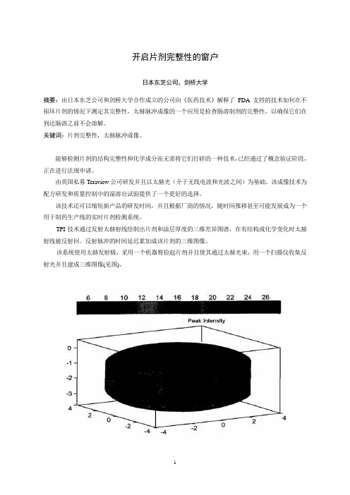
该系统使用太赫发射极,采用一个机器臂捡起片剂并且使其通过太赫光束,用一个扫描仪收集反射光并且建成三维图像(见图)。
技术研发太赫技术发源于二十世纪九十年代中期13本东芝公司位于英国的东芝欧洲研究中心,该中心与剑桥大学的物理学系有着密切的联系。
日本东芝公司当时正在研究新一代的半导体,研究的副产品是发现了这些半导体实际上是太赫光非常好的发射源和检测器。
二十世纪九十年代后期,日本东芝公司授权研究小组寻求该技术可能的应用,包括成像和化学传感光谱学,并与葛兰素史克和辉瑞以及其它公司建立了关系,以探讨其在制药业的应用。
虽然早期的结果表明该技术有前景,但日本东芝公司却不愿深入研究下去,原因是此应用与日本东芝公司在消费电子行业的任何业务兴趣都没有交叉。
这一决定的结果是研究中心的首席执行官DonArnone和剑桥桥大学物理学系的教授Michael Pepper先生于2001年成立了Teraview公司一作为研究中心的子公司。
TPI imaga 2000是第一个商品化太赫成像系统,该系统经优化用于成品片剂及其核心完整性和性能的无破坏检测。
- 1、下载文档前请自行甄别文档内容的完整性,平台不提供额外的编辑、内容补充、找答案等附加服务。
- 2、"仅部分预览"的文档,不可在线预览部分如存在完整性等问题,可反馈申请退款(可完整预览的文档不适用该条件!)。
- 3、如文档侵犯您的权益,请联系客服反馈,我们会尽快为您处理(人工客服工作时间:9:00-18:30)。
a r X i v :g r -q c /0610047v 2 27 M a r 2007Testing General Relativity with Atom InterferometrySavas Dimopoulos,Peter W.Graham,Jason M.Hogan,and Mark A.KasevichDepartment of Physics,Stanford University,Stanford,California 94305(Dated:February 6,2008)The unprecedented precision of atom interferometry will soon lead to laboratory tests of general relativity to levels that will rival or exceed those reached by astrophysical observations.We propose such an experiment that will initially test the equivalence principle to 1part in 1015(300times better than the current limit),and 1part in 1017in the future.It will also probe general relativistic effects—such as the non-linear three-graviton coupling,the gravity of an atom’s kinetic energy,and the falling of light—to several decimals.In contrast to astrophysical observations,laboratory tests can isolate these effects via their different functional dependence on experimental variables.PACS numbers:04.80.-y,,03.75.DgExperimental tests of general relativity (GR)have gone through two major phases.The original tests of the perihelion precession and light bending were followed by a golden era from 1960until today (see e.g.[1]).These tests were in part motivated by alternatives to GR,such as Brans-Dicke [2].More recently,the cosmological con-stant problem suggests that our understanding of gravity is incomplete,motivating a number of proposals for mod-ifying GR at large distances [3].Also,alternatives to the dark matter hypothesis have led to theories where gravity changes at slow accelerations or galactic scales [4].Presently,most GR parameters have been tested at the part per thousand level.Typical GR tests involve the study of planets,stars,or light moving over astro-nomical distances for extended periods of time.In this letter we argue that high-precision tests of GR are possi-ble in the lab using the motion of individual,quantum-mechanical atoms moving over short distances for brief periods of time.Specifically,atom interferometry can lead to laboratory tests of GR that are competitive with astrophysical tests and potentially superior to them in the long run.There are two reasons for this:one is the high accuracy of atomic physics methods –reaching,for example,16-decimal clock synchronization [5].The second is that such an experiment has several control pa-rameters,allowing us to isolate and measure individual relativistic terms and control backgrounds by using their scalings with these parameters.In contrast,with astro-physical observations we have limited control and often cannot disentangle the relativistic effects.Our proposed experiment relies on light-pulse atom in-terferometers.These have already achieved extreme ac-curacy as inertial sensors in a variety of configurations including gyroscopes [6],gradiometers [7],and gravime-ters [8].The first generation of atom inteferometry ex-periments will push the limits on the Principle of Equiva-lence (PoE)and begin measuring GR effects and placing constraints on parametrized post-Newtonian (PPN)pa-rameters,as shown in the third column of Table I.The next three columns show further possible improvements.To calculate the effect of GR corrections to NewtonianTestedlimit initial upgrade future future3×10−1310−1510−1610−1710−19PPN (β,γ)ris the Earth’s gravitational potential,and βand γare PPN parameters.The major effect ne-glected here is the rotation of the Earth.The Newtonian effects of the rotation are an important background,but the possible rotation related GR effects are undetectable in the interferometer configurations considered bining the geodesic equations for the spatial x i (i =1,2,3)and t ,the coordinate acceleration of an atomin the frame of Eqn.1(with v =dxdt=− ∇(φ+(β+γ)φ2)+γ(3( v ·ˆr )2−2 v 2) ∇φ+2 v ( v · ∇φ)(2)This illustrates two classes of leading GR corrections to the Newtonian force law.The ∇φ2terms are related to the non-linear (non-Abelian)nature of gravity indicat-ing that gravitational energy gravitates through a three-graviton vertex.To see this,note the divergence of the gravitational field given in Eqn.2is nonzero because of these terms.Just as for an electric field,a nonzero di-vergence of the gravitational field implies a local source2T 2TTimeLH e i g h t FIG.1:A space-time diagram of a light pulse atom interfer-ometer.The black curves indicate the geodesic motion of a single atom near the surface of the ser light used to manipulate the atom is incident from above (light gray)and below (dark gray)and travels along null geodesics.The finite speed of the light has been exaggerated.density,in this case a local energy density,proportional to that divergence ∇·∇φ2=2(∇φ)2.So the local energy density is proportional to the field squared.This energy gives rise to the ∇φ2terms.The other terms are velocity dependent forces related to the gravitation of the atom’s kinetic energy.The non-linear GR corrections are smaller than Newtonian gravity by a factor of φ∼7×10⁻¹⁰while the velocity dependent forces are smaller by v 2∼10−15for the atom velocities we are considering.We will show that the non-linear terms can only be measured through a gradient of the force produced and so are reduced by an additional factor of 10m2−π−πp µdx µ∼p ·∆ x (4)where,for coordinate independence,the integral is overthe null geodesic connecting the classical endpoints of the two arms of the interferometer,andSize(rad)1.3×10⁸−k eff(∂r g)T3v L1st gradient 3.4×101(2−2β−γ)k effgφT2GR5.12k eff(∂2r g)T4v2L2nd gradient 6.3×10⁻⁶(2−2β−γ)k eff∂r(gφ)T3v L GR1st grad 8.−6×10⁻⁷R3outside the mass distribution in thecenter of mass frame in Newtonian gravity,the R scaling of this term may provide a way to distinguish it from a Newtonian gravitationalfield.A differential measure-ment of the R scaling would involve two interferometers running simultaneously at different heights.The same laser should be used for both interferometers to reduce systematics and technical noise.At best,such a differen-tial setup would measure the gradient of this term,thus reducing it to∼10−7rad or∼10−15g,if the interferom-eters are placed10m apart.In practice,a measurement of this term or of the third GR term,k eff∂r(gφ)T3v L,could be masked by the New-tonian gravity of local mass inhomogeneities.One pos-sible approach to rejecting the Newtonian background is to employ three such differential accelerometer measure-ments along three mutually orthogonal axes.If these three measurements are added together,all Newtonian gravity gradient contributions to the measurement mustcancel,since,in the absence of a local source,the diver-gence of the gravitationalfield is zero in Newton’s theory. In GR this divergence is not zero,as can be seen fromthe∇φ2term in Eqn.2.For such a strategy to be effec-tive,however,the Newtonianfield needs to be sufficientlyslowly varying over the measurement baseline,which canbe tested by varying the baseline.Table I summarizes the experimental precision possiblefor measuring GR effects and the PPN parametersβandγ.The initial atom interferometry limits assume the10m experiment described earlier,but many upgrades are pos-sible.For example,using200 k beamsplitters increases the sensitivity by a factor of∼10.Expanding to a100mlong interferometer would increase the sensitivity by afactor of10.For the GR terms this improvement would be even larger;for example,terms6and7scale as L2(v L∼T,L∼T2).With these improvements it is pos-sible to reach limits on the PPN parameters of∼10−4, competitive with present limits.Finally,the noise perfor-mance can be improved by using entangled states insteadof uncorrelated atom ensembles[22].For a suitably en-tangled source,the Heisenberg limit is SNR∼n,a factor √of。