4-输入输出
C语言课件第4章-键盘输入与屏幕输出

C语言课件第4章-键盘输入与屏幕输出的内容包括键盘输入函数、屏幕输出函 数等。该章节将详细介绍C语言中与输入输出有关的知识。
概述
本章将介绍C语言中的键盘输入和屏幕输出的基本概念和原理,帮助读者理解 输入输出的重要性和操作方法。
键盘输入函数
scanf()
用于从键盘接收输入,并按照指定的格式进行 解析和赋值。
代码审查
通过格式化输出,我们可以更好地理解和审查他人 编写的代码。
练习题:输入输出实战
通过一些练习题的实践,加深对键盘输入和屏幕输出的理解,并提高实际编 程能力。
1
字符数组
用于存储字符串的一组连续的字符。
2
g ets()函数
用于从键盘读取一行字符串并存储到指定的字符数组中。
字符串和p uts()函数
1
字符串
是由字符组成的一串数据,以空字符'\0'结尾。
2
p u ts ()函数
用于将字符串输出到屏幕上。
格式化输出
代码示例
展示如何使用格式化输出来美化代码的显示,提高键盘逐个字符地读取输入。
屏幕输出函数
printf()
用于在屏幕上输出指定的字符串和变量的值。
putchar()
用于在屏幕上逐个字符地输出。
输入输出格式化控制
格式化控制允许我们在输入和输出时对数据进行格式化的操作,包括对整数、 浮点数、字符等进行格式化输出。
字符数组和g ets()函数
福建师范大学 c语言 第四章输入与输出
第四章:输入与输出
字符输入函数(getchar)p98
格式:getchar( ) 功能:从键盘读一字符 返值:正常,返回读取的代码值;出错,返回EOF(-1)
/*use of getchar function*/ 运行结果: #include <stdio.h> Enter a character:A↵ void main() A--->hex41 { int c; printf("Enter a character:"); c=getchar(); printf("%c--->hex%x\n",c,c); }
9/24
第四章:输入与输出
转义序列2/2
\”——” \\——\
printf("\"Hello!\""); Output: /* prints "Hello!" */ printf("\\"); Output: /* prints one \ character */
10/24
第四章:输入与输出
格式化输入(scanf函数p29)
输入实数时不能规定精度
15/24
第四章:输入与输出
scanf输入字符和字符串
char ch; char name[10]; scanf(“%c%s”, &ch, name); printf(“%c %s”, ch, name); 键入:a zhangsan↵ 输出:a zhangsan char c1,c2,c3; scanf(“%c%c%c”,&c1,&c2,&c3); printf(“%c%c%c”, c1,c2,c3); 键入:a b c↵ 输出:a b
4-20ma输入、输出485 24位AD分辨率传感器说明

4-20ma转RS485 232 24位AD分辨率采集传感器随信号隔离器近年的发展分析1.目前信号隔离器的应用领域和市场发展的情况近几年来,信号隔离器分别在石油、化工、水泥、建材、钢铁、电力等行业得到了广泛的应用。
其中国产的产品销量2009年达到了100万台左右,产值达6亿人民币左右。
这还不包括从国外直接进口的同类产品。
这就说明了一个问题,信号隔离器的发展是非常快的。
2.随着时代不同技术的发展和应用的深入,隔离器也正在向低功耗、小体积、超薄型、密集型方向发展。
其应用前景十分广阔。
不同领域里信号隔离器的使用时非常广泛的。
也是其功能的最好体现。
3.在这同时,很多厂家还开发智能型信号隔离器,它除了具备常规信号隔离器的优异性能外,还加入了CPU控制单元,具有现场可编程功能(即万能输入型)及通信功能。
如美国ACI 系列产品,日本M-SYSTEM的M3系列,日本FUJI的PWB系列等。
这种高智能的信号隔离器有很高的应用灵活性,可以有效地减少库存数量,能够降低资金积压。
这种智能型的信号隔离器必将成为这一领域的主流。
这也是最近比较盛行的智能型信号隔离器。
总之,隔离器产品及技术具有很好的市场和发展前景,值得我们特别重视。
目前,我公司具有了5~10万台的生产能力。
还要加大这方面的技术和生产投入,为公司发展开辟新的途径,从而达到提高公司规模和效益的目的。
产品特点:● 16路模拟信号采集,隔离转换RS-485/232输出● 采用24位AD转换器,测量精度优于0.05%● 通过RS-485/232接口可以程控校准模块精度● 信号输入/ 输出之间隔离耐压3000VDC●宽电源供电范围:8 ~ 32VDC● 可靠性高,编程方便,易于应用● 标准DIN35导轨安装,方便集中布线● 用户可编程设置模块地址、波特率等● 支持Modbus RTU 通讯协议,自动识别协议● AD转换速率可以编程设定典型应用:● 模拟信号测量、监测和控制● RS-485远程I/O,数据采集● 智能楼宇控制、安防工程等应用系统● RS-232/485总线工业自动化控制系统● 工业现场信号隔离及长线传输● 设备运行监测● 传感器信号的测量● 工业现场数据的获取与记录● 医疗、工控产品开发● 4-20mA或0-5V信号采集产品概述:IBF29产品实现传感器和主机之间的多路信号采集,用来检测最多16路模拟信号。
义务教育版(2024)信息科技六年级全一册 第4课 输入输出与计算 教案

教学方法
讲授法、演示法、讨论法、实践法。
教学过程设计
教学环节
教师活动
学生活动
导入新课
o展示一段关于智能交通系统的视频,包括红绿灯、自动感应门等场景。
o提问学生:“在视频中,你看到了哪些控制系统?它们是如何工作的?”
o观看视频,认真观察视频中的控制系统。
o积极回答教师的问题,分享自己对控制系统的认识。
o布置拓展与提升的任务:
o任务一:实现机器人以一定速度直行的功能,然后分析机器人工作过程中的输入、计算和输出三个环节。
o任务二:分析自动门的输入和输出,并思考它是通过什么设备获取输入信号的。
o讲解任务的具体要求和操作步骤。
o巡视学生的实践操作过程,给予指导和帮助。
o明确任务要求,选择其中一个任务进行实践操作。
课题
输入输出与计算
课时
1课时
年级
六年级
教学环境
教学内容分析
本节课主要介绍了控制系统工作过程的三个环节,即输入、计算和输出。通过分析自己看到红灯的反应、声控灯的工作过程以及用计算机输入汉字的过程,让学生理解输入、计算和输出在控制系统中的作用,并能结合具体案例进行描述。此外,通过拓展与提升活动,让学生进一步了解机器人和自动门的工作过程,培养学生的问题分析能力和计算思维能力。
o提问学生:“我们在使用计算机输入汉字时,用到了哪些设备?”
o引导学生说出所使用的输入设备和输出设备。
o展示用拼音输入法输入汉字的过程示意图,讲解计算机输入汉字的输入、计算和输出环节。
o认真思考教师提出的问题,结合自己的经验回答。
o倾听教师的讲解,理解输入、计算和输出的概念。
o结合情境,思考声控灯的工作过程。
《c语言程序设计教学资料》第4章-键盘输入与屏幕输出

数据存储
将用户输入的数据存储在 适当的变量中,以便后续 处理或使用。
输入验证与错误处理
数据有效性检查
在处理用户输入之前,应验证输 入数据的合法性和有效性,例如 检查输入的数字是否在合理范围 内。
错误处理
当用户输入无效或出现错误时, 应采取适当的错误处理措施,例 如提示用户重新输入或给出错误 提示信息。
fgets函数
与gets函数类似,但不加锁,适用于多线 程环境。
Hale Waihona Puke 用于从文件读取一行字符串。
自定义输入输出函数
自定义输入函数
根据实际需求,编写自定义的输入函数,可以封装标准输入 函数或提供更方便的接口。
自定义输出函数
根据实际需求,编写自定义的输出函数,可以封装标准输出 函数或提供更丰富的功能。
感谢您的观看
错误处理与异常情况
输入错误处理
当用户输入的数据类型不正确或超出范围时,可以使用条件语句和循环结构进行 错误处理。
异常情况处理
在程序运行过程中可能出现异常情况,如数组越界、除数为零等,需要使用异常 处理机制来捕获并处理这些异常情况。
04
输入输出函数库
标准输入输出库函数
01
02
03
04
printf函数
02
屏幕输出
基本的输出函数
printf()
用于在控制台输出格式化 的文本。
puts()
用于输出一个字符串到控 制台。
disp()
用于在屏幕上显示一个变 量的值。
控制台输出格式化
使用格式说明符
例如,`%d`表示整数,`%f`表示浮点数,`%c`表示字符等。
输出宽度、精度和小数点
例如,`%5d`表示输出的整数宽度为5,`%.2f`表示浮点数输出保留 两位小数。
(计算机控制技术)第4章计算机过程输入输出通道

03
输出通道技术
模拟量输出通道
模拟量输出通道的作用是将计 算机输出的数字信号转换为模 拟信号,以驱动各种执行机构
。
常见的模拟量输出通道有电压 输出型和电流输出型两种,它 们通过不同的方式将数字信号
转换为模拟信号。
电压输出型模拟量输出通道的 优点是电路简单、成本低,适 用于输出信号较小、对精度要 求不高的场合。
03
输出通道的驱动能力是指其能够驱动执行机构或控制设备的能力,包 括最大输出电压、最大输出电流等参数。
04
选择具有足够驱动能力的输出通道可以保证系统的正常运行和稳定性。
04
输入输出通道的信号处 理与接口技术
信号的预处理技术
信号的放大与衰减
根据信号的幅度调整,确 保信号在传输过程中保持 稳定。
信号的滤波
去除噪声和其他干扰,提 高信号质量。
信号的整形
将不规则或非标准信号转 换为适合传输和处理的信 号。
信号的转换技术
A/D转换将模拟信号转换为数字信号,源自 于计算机处理。D/A转换
将数字信号转换为模拟信号,便于 实际应用。
光电转换
将光信号转换为电信号,或反之。
信号的传输与接口技术
总线技术
实现多个设备之间的数据传输和通信。
数字量输出通道的作用是将计算机输出的数字 信号转换为控制信号,以驱动各种控制设备。
晶体管输出型数字量输出通道的优点是响应速度 快、驱动能力强,适用于需要快速响应的场合。
输出通道的负载特性与驱动能力
01
输出通道的负载特性是指执行机构或控制设备的输入阻抗、输入电压、 输入电流等参数。
02
了解负载特性有助于选择合适的输出通道类型和规格,以确保系统的 稳定性和可靠性。
4端口环行器的工作原理
4端口环行器的工作原理
4端口环行器通常是指具有四个输入/输出端口的环行器(circulator)。
环行器是一种被广泛用于射频(Radio Frequency,RF)和微波系统中的无源器件,它具有在特定频率范围内引导信号流动的能力。
下面是4端口环行器的基本工作原理:
1.输入与输出端口的分配:4端口环行器通常有三个输入/输出
端口,分别标记为端口1、2、3,并有一个反射端口,标记为端口4。
端口1 上的信号在顺时针方向旋转到端口2,端口2 上的信号旋转到端口3,端口3 上的信号旋转到端口1。
反射端口4 则用于将信号反射回原来的端口。
2.非互斥传输:4端口环行器的一个关键特性是非互斥传输,即
它可以同时允许信号在两个方向上传输,而不会相互干扰。
例如,如果信号从端口1 输入,它可以旋转到端口2,并且在同一时间,如果有
信号从端口3 输入,它可以旋转到端口4。
3.旋转磁场:4端口环行器的工作类似于一个旋转磁场,通过不
同的端口引导信号。
这种工作原理使得环行器在射频和微波系统中可以用于一些特定的应用,如匹配网络、天线系统、雷达系统等。
4.应用:4端口环行器的典型应用包括将天线与发射器和接收器
分离、用于匹配网络以提高信号传输效率、在雷达系统中用于波束旋转等。
总的来说,4端口环行器是一种多功能的器件,通过其独特的信号引导特性,可以在无源的情况下实现信号的定向传输和反射。
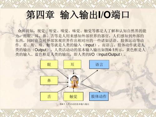
第四章 输入输出IO端口
//包含头文件 //代码的主程序 //设置PA[0..5]为输出端口 //关闭所有的等 //无限循环 //东西方向亮绿灯 //南北方向亮红灯 //延时50秒 //关闭东西方向绿灯 // //东西方向亮黄灯 //延时5秒 //关闭东西方向黄灯 //关闭南北方向红灯 //东西方向亮红灯 //南北方向亮绿灯 //延时50秒 //关闭南北方向绿灯 //南北方向亮黄灯 //延时5秒 //关闭南北方向黄灯 //关闭东西图4-1 人类活动的基本输入输出
肢体动作
• 对于单片机而言,了解周围环境的情况、 感知外界事物的变化同样需要像人类的各 种感官这样的输入部件(即输入端口I); 同时,单片机也要对它所感知的事物及变 化做出相对应的处理,也就必须具备输出 部件(即输出端口O)。因此,输入输出 输入输出 I/O端口就是单片机感知外部世界和对外部 端口就是单片机感知外部世界和对外部 世界做出反应的部件, 世界做出反应的部件,通过输入端口获取 外部事物的变化情况, 外部事物的变化情况,并通过输出端口对 外部世界做出回应。 外部世界做出回应
4.2.2 拨码开关的检测
#include <iom16v.h> Main(void) { DDRA = 0xff; DDRC = 0x00; PORTC = 0xff; while(1) { PORTA = PINC; } }
//包含头文件 //代码的主程序 //设置PA端口为输出端口 //设置PC端口为输入端口 //启用PC口内部上拉电阻 //无限循环 //PA口输出PC口的检测值
4.4.1 “交通灯”模型硬件电路及源代码分析 交通灯” 交通灯
#include <iom16v.h> Main(void) { DDRA = 0x3f; PORTA = 0x3f while(1) { PORTA &= ~(1<<0); PORTA &= ~(1<<5); DelayS(50); PORTA |= (1<<0); PORTA &= ~(1<<1); DelayS(5); PORTA |= (1<<1); PORTA |= (1<<5); PORTA &= ~(1<<2); PORTA &= ~(1<<3); DelayS(50); PORTA |= (1<<3); PORTA &= ~(1<<4); DelayS(5); PORTA |= (1<<4); PORTA |= (1<<2); } }
Fortran PPT课件-(4简单的输入输出

1.6 简单的输入与输出
注意: 输入数据的个数要和输入表中变量的个 数相等; 输入字符数据时!若输入的字符串中含有 空格或逗号!则这个字符串一定要用撇号 括起来。
1.6 简单的输入与输出
表控输出语句
输出语句的形式
WRITE(unit=u,*)输出表 PRINT*,输出表 √ WRITE*,输入表 × write(unit=5,*)a,b,c = write(5,*)a,b,c write(*,*)a,b,c print*, a,b,c ! 从显示屏幕输入 u为输入设备号,*号表示表控输出,unit= 可以省略; 输出表可以是变量、数组元素名、数组名、 子串名等,它们之间用逗号分隔开。
1.6 简单的输入与输出
表控输入语句
输入语句的形式 READ(unit=u,*)输入表 READ*,输入表 read(unit=5,*)a,b,c = read(5,*)a,b,c read(*,*)a,b,ห้องสมุดไป่ตู้ ! 从键盘输入 u为输入设备号,*号表示表控输入,unit= 可以省略; 输入表可以是变量、数组元素名、数组名、 子串名等,它们之间用逗号分隔开。
charpter4_数据的输入输出

13
例题:
Private Sub Form_Click() x=5 y=6 Print "x=", x Print "y=", y Print Print "x乘y的结果是:"; x * y End Sub
14
二、与Print有关的函数
1. Tab(n) 绝对定位,用于把光标向后移动n个字符,n从第一 列开始计算,与输出的位置要用“;”隔开
16
练习:
熟悉Print语句以及Tab函数和Spc函数。打印出如图418所示的商品库信息。
图4-18 商品库存信息
17
三、打印机输出
1. 直接输出,将信息直接送到打印机输出。 Printer.print[表达式] 2. 窗体输出 [窗体名.] print 窗体输出的好处是可以在屏幕上观察并调整输出格式和效果, 满意后再打印输出,这样可以提高效率,节约纸张。 注意:如果要进行窗体输出,先将输出窗体的AutoRedraw 属性设置为True,以便保存窗体上的信息。
6
练习:
编制一个程序,输入矩形的长和宽,输出矩形的面积。要求: ① 采用文本框和Print语句结合的方式进行输入和输出。 ② 采用InputBox函数和MsgBox函数结合的方式进行输入和输 出。
Private Sub Command1_Click() Dim a, b, s As Single a = Val(Text1.Text) b = Val(Text2.Text) Private Sub Command1_Click() s=a*b Dim a, b, s As Single Print "矩形面积是:" & s a = InputBox("请输入矩形的长:", "矩形的长") End Sub b = InputBox("请输入矩形的宽:", "矩形的宽") s=a*b MsgBox "矩形的面积是:" & s End Sub
第4章开关量信号的输入输出

3 磁性开关与单片机的接口电路
图4-4a 霍尔元件差动放大电路
磁性开关一般由霍尔元 件型、干簧管型等,常用于 监测门窗是否打开及各种脉 冲式水表气表。此时,需在 普通转盘计数的仪表中加装 霍尔元件和磁铁,即可构成 基于磁电转换技术的传感器。
图4-4a所示的电路中,若有磁场作用,则霍尔元件会输 出120mV电压信号,经过约40倍的差动放大器放大整形后,在 Vout上输出高电平;否则输出低电平。霍尔元件和运放电路一 起,构成了开关型霍尔传感器,将这个信号输送到单片机的I/ O口或外部中断引脚,即可实现霍尔检测开关控制 .
2.开关量信号的特点是什么?
只有开和关、通和断、高电平和低电平两种状 态的信号叫开关量信号,在智能仪器的电子电路中, 通常用二进制数0和1来表示。
智能仪器原理与设计------第4章 开关量信号的输入输出
3.开关量信号的作用? 开关量输入、输出部分是智能仪器与外部设备的联系部件,
智能仪器通过接受来自外部设备的开关量输入号和向外部设备 发送开关量信号,实现对外部设备状态的检测、识别和对外部 执行元器件的驱动和控制。 4.常见电子开关都有哪些?
智能仪器原理与设计------第4章 开关量信号的输入输出
4.1.2 开关量输入接口
1 扳键开关与单片机的接口电路
图4-2 扳键开关与单片机的接口电路
图中, 扳键开关将高电平
或低电平经单片机的I/O引脚 输入缓冲器74LS244,74LS244 的数据输入端与单片机89C51 的P0口相连接,用于8位数据 的传送,89C51的P1.7和/RD作 为74LS244的选通信号 。当扳 键开关合上时,将向P0口的相
智能仪器原理与设计------第4章 开关量信号的输入输出
《c语言程序设计教学资料》第4章---键盘输入与屏幕输出

编辑ppt
编辑ppt
格式化输出
例: m.n 例:int a=1234; float f=123.456; char ch=‘a’; printf(“%8d\n%2d\n”,a,a); printf(“%f\n%8f\n%8.1f\n%.2f\n%.2e\n”,f,f,f,f,f); printf(“%3c\n”,ch);
float f=123.456; printf(“%f\n%10f\n%10.2f\n%.2f\n%-10.2f\n”,f,f,f,f ,f ); }
编辑ppt
%e格式符
指定以指数形式输出实数 VC++给出小数位数为6位
指数部分占5列 小数点前必须有而且只有1位非零数字 printf(”%e”,123.456); 输出:1.234560 e+002
补空格。
编辑ppt
输出实数时的有效位数。
#include <stdio.h> void main() { float x,y;
x=111111.111; y=222222.222; printf(″%f″,x+y); }
编辑ppt
例4.8 输出实数时指定小数位数。
#include <stdio.h> void main() {
有以下几种用法:
① %f。不指定字段宽度,由系统自动指定字段宽度,使整数
部分全部输出,并输出6位小数。应当注意,在输出的数字中
并非全部数字都是有效数字。单精度实数的有效位数一般为7位。
②%m.nf。指定输出的数据共占m列,其中有n位小数。如果
义务教育版(2024)六年级全一册信息科技 第4课 输入输出与计算 教案

课题输入输出与计算单元第一单元学科信息科技年级六年级教材分析【学情分析】在社会生产和人们生活当中,广泛存在着各种各样的控制系统,如流动生产线、公共交通系统、空调、个人计算机、手机等各种大大小小的控制系统。
它们遵循自身的过程与控制原理,都从外界获得输入,经过计算产生输出,从而给生产和生活提供各种服务。
有的控制系统输出的结果还会被传回去影响输入,重新进行计算,形成新的输出,周而复始。
正是各种各样的控制系统,使人们的学习、生活、工作变得更加便利。
本单元对应课程标准中“通过体验和认识身边的过程与控制,了解过程与控制可以抽象为包含输入、计算和输出三个典型环节的系统”这条内容要求,是整个模块的开篇,起到引领学生入门的作用。
本单元在教学内容设计上,遵循小学生的认知规律,首先从学生能直观感受到或接触到的设备出发,引导他们结合实际操作设备的经历逐渐建立对控制系统的感知;然后由触手可及的开关出发,引发学生思考开与关操作导致的控制系统状态改变,其背后引发了怎样的一个过程,从而激发他们探索控制系统内部奥秘的兴趣;接着,让学生通过角色扮演或情景剧,“成为”控制系统工作过程中的一部分,感受控制的作用;最后从使用者的角度,分析控制系统工作的典型环节(以下称三个环节):输入、计算和输出。
整个单元的教学,从身边看得见摸得着的设备出发,从熟悉的开与关操作着手,逐渐上升到相对抽象的控制系统内部的工作过程。
这样的设计符合学生的认知规律,有利于他们在熟知的生活场景中产生进一步学习的兴趣。
在教学处理上,本单元的关注点是引导学生了解控制系统及其工作过程,虽然出现了控制系统、过程、控制等术语,但不需要进行过多解读。
这个阶段的学生,只需要知道这些术语,并能联系具体控制系统即可。
【内容结构】学习目标1. 信息意识:体验物理世界与数字世界深度融合的环境,感受控制系统在社会生产和人们生活中的广泛应用。
2. 计算思维:能基于对过程与控制的理解,感受控制系统中“计算”的作用。
04-第四章 Lingo的输入输出及界面

Excel07版:在公式-》定义 的名称-》名称管理器 中
第四章 Lingo的输入输出及界面
输入输出函数
Lingo函数
4.@ranged(variable_or_row_name) 为了保持最优基不变,变量的费用系数或约束行的右端项允许减 少的量。 5.@rangeu(variable_or_row_name) 为了保持最优基不变,变量的费用系数或约束行的右端项允许增 加的量。
第四章 Lingo的输入输出及界面
输入输出函数
Lingo函数
! Here is the data; DATA: CAPACITY = 60 55 51 43 41 52; DEMAND = 35 37 22 32 41 32 43 38; COST = 6 2 6 7 4 2 5 9 49538582 52197433 76739271 23957265 红色的数据部分应该从程序中分离! 5 5 2 2 8 1 4 3; ENDDATA
第四章lingo的输入输出及界面lingo的选项第四章lingo的输入输出及界面lingo的选项第四章lingo的输入输出及界面lingo的选项第四章lingo的输入输出及界面lingo的选项第四章lingo的输入输出及界面lingo的选项第四章lingo的输入输出及界面lingo的选项第四章lingo的输入输出及界面lingo的选项第四章lingo的输入输出及界面lingo的选项第四章lingo的输入输出及界面lingo的选项第四章lingo的输入输出及界面lingo的选项第四章lingo的输入输出及界面lingo的选项第四章lingo的输入输出及界面lingo的选项第四章lingo的输入输出及界面lingo的选项第四章lingo的输入输出及界面lingo的选项第四章lingo的输入输出及界面lingo的选项第四章lingo的输入输出及界面lingo的选项第四章lingo的输入输出及界面lingo的选项第四章lingo的输入输出及界面lingo的选项第四章lingo的输入输出及界面lingo的选项第四章lingo的输入输出及界面lingo的选项第四章lingo的输入输出及界面lingo的选项第四章lingo的输入输出及界面lingo的选项第四章lingo的输入输出及界面lingo的选项第四章lingo的输入输出及界面
数字系统平台 - Digilent DIO4 输入 输出模块说明书
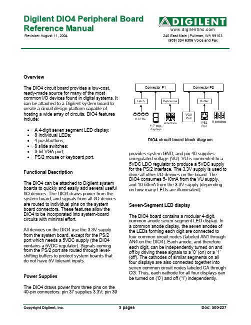
D i g i l e n t D I O4P e r i p h e r a l B o a r d R e f e r e n c e M a n u a lRevision: August 11, 2004 246 East Main | Pullman, WA 99163(509) 334 6306 Voice and FaxOverviewThe DIO4 circuit board provides a low-cost, ready-made source for many of the most common I/O devices found in digital systems. It can be attached to a Digilent system board to create a circuit design platform capable of hosting a wide array of circuits. DIO4 features include:• A 4-digit seven segment LED display; •8 individual LEDs;• 4 pushbuttons;•8 slide switches;•3-bit VGA port;•PS/2 mouse or keyboard port. Functional DescriptionThe DIO4 can be attached to Digilent system boards to quickly and easily add several useful I/O devices. The DIO4 draws power from the system board, and signals from all I/O devices are routed to individual pins on the system board connectors. These features allow the DIO4 to be incorporated into system-board circuits with minimal effort.All devices on the DIO4 use the 3.3V supply from the system board, except for the PS/2 port which needs a 5VDC supply (the DIO4 contains a 5VDC regulator). Signals coming from the PS/2 port are routed through level-shifting buffers to protect system boards that do not have 5V tolerant inputs.Power SuppliesThe DIO4 draws power from three pins on the 40-pin connectors: pin 37 supplies 3.3V; pin 39unregulated voltage (VU). VU is connected to a 5VDC LDO regulator to produce a 5VDC supply for the PS/2 interface. The 3.3V supply is used to drive all other I/O devices on the board. The DIO4 consumes 5-10mA from the VU supply, and 10-50mA from the 3.3V supply (depending on how many LEDs are illuminated).Seven-Segment LED displayThe DIO4 board contains a modular 4-digit, common anode seven-segment LED display. In a common anode display, the seven anodes of the LEDs forming each digit are connected to four common circuit nodes (labeled AN1 through AN4 on the DIO4). Each anode, and therefore each digit, can be independently turned on and off by driving these signals to a ‘0’ (on) or a ‘1’ (off). The cathodes of similar segments on all four displays are also connected together into seven common circuit nodes labeled CA through CG. Thus, each cathode for all four displays can be turned on (‘0’) and off (‘1’) independently.This connection scheme creates a multiplexed display, where driving the anode signals and corresponding cathode patterns of each digit in a repeating, continuous succession can create a 4-digit display. In order for each of the four digits to appear bright and continuously illuminated, all four digits should be driven once every 1 to 16ms (for a refresh frequency of 1KHz to 60Hz). For example, in a 60Hz refresh scheme, each digit would be illuminated for ¼ of the refresh cycle, or 4ms. The controller must assure that the correct cathode pattern is present when the corresponding anode signal is driven. To illustrate the process, if AN1 is driven low while CB and CC are driven low, then a “1” will be displayed in digit position 1. Then, if AN2 is driven low while CA, CB and CC are driven low, then a “7” will be displayed in digit position 2. If AN1 and CB, CC are driven for 4ms, and then AN2 and CA, CB, CC are driven for 4ms in an endless succession, the display will show “17” in the first two digits. An example timing diagram is provided below.Discrete LEDsEight individual LEDs are provided for circuit outputs. The LED cathodes are tied to GND via 270-ohm resistors, and the LED anodes are driven from a 74HC373. The ‘373 allows LED data to be latched on the DIO4, so that theLD# signals from the system board do not need to be driven continuously (the LD# signals use connector pins that are used in the “system bus” on some Digilent boards). If the system bus is not needed, then the LDG signal can be tied high.LD #LDGButton InputsThe DIO4 contains 4 N.O. (normally open) pushbuttons. Button outputs are connected to Vdd via a 4.7K resistor. When the button is pressed, the output is connected directly to GND. This results in a logic signal that is low only while the button is actively pressed, and high at all other times. The buttons are debounced with an RC filter and Schmidt-trigger inverter as shown in the figure below. This circuit creates a logic high signal when the button is pressed. The debounce circuit provides ESD protection and creates a signal with clean edges, so the BTN# signals can be used as clock signals if desired.BTN#Switch InputsThe eight slide switches on the DIO4 can be used to generate logic high or logic low inputs to the attached system board. The switches exhibit about 2ms of bounce, and no active debouncing circuit is employed. A 4.7K-ohm series resistor is used for nominal input protection.PS2 PortThe DIO4 board includes a 6-pin mini-DIN connector that can accommodate a PS2 mouse or PS2 keyboard connection. A 5VDC regulator and voltage-mapping buffers are provided on the board to interface lower voltage system boards with keyboards and/or mice.PS2 ConnectorBottom-uphole patternPin DefinitionsPin Function1 Data2 Reserved3 GND4 Vdd5 Clock6 ReservedBoth the mouse and keyboard use a two-wire serial bus (including clock and data) to communicate with a host device, and both drive the bus with identical signal timings. Both use11-bit words that include a start, stop and odd parity bit, but the data packets are organized differently, and the keyboard interface allows bi-directional data transfers (so the host device can illuminate state LEDs on the keyboard). Bus timings are shown below. The clock and data signals are only driven when data transfers occur, and otherwise they are held in the “idle” state at logic ‘1’. The timings define signal requirements for mouse-to-host communications and bi-directional keyboard communications.TCLKTKeyboardThe keyboard uses open collector drivers so that either the keyboard or an attached host device can drive the two-wire bus (if the host device will not send data to the keyboard, then the host can use simple input-only ports).PS2-style keyboards use scan codes to communicate key press data (nearly all keyboards in use today are PS2 style). Each key has a single, unique scan code that is sent whenever the corresponding key is pressed. If the key is pressed and held, the scan code will be sent repeatedly once every 100ms or so. When a key is released, a “F0” key-up code is sent, followed by the scan code of the released key. If a key can be “shifted” to produce a new character (like a capital letter), then a shift character is sent in addition to the original scan code, and the host device must determine which character to use. Some keys, called extended keys, send an “E0” ahead of the scan code (and they may send more than one scan code). When an extended key is released, an “E0 F0” key-up code is sent, followed by the scan code. Scan codes for most keys are shown in the figure below.A host device can also send data to the keyboard. Below is a short list of some often-used commands.ED Set Num Lock, Caps Lock, and Scroll Lock LEDs. After receiving an “ED”, the keyboardreturns an “FA”; then the host sends a byte toset LED status: Bit 0 sets Scroll Lock; bit 1 setsNum Lock; and Bit 2 sets Caps lock. Bits 3 to 7are ignored.EE Echo. Upon receiving an echo command, the keyboard replies with “EE”.F3 Set scan code repeat rate. The keyboard acknowledges receipt of an “F3” by returning an“FA”, after which the host sends a second byteto set the repeat rate.FE Resend. Upon receiving FE, the keyboard re-sends the last scan code sent.FF Reset. Resets the keyboard.The keyboard should send data to the host only when both the data and clock lines are high (or idle). Since the host is the “bus master”, the keyboard should check to see whether the host is sending data before driving the bus. To facilitate this, the clock line can be used as a “clear to send” signal. If the host pulls the clock line low, the keyboard must not send any data until the clock is released (host-to-keyboard data transmission will not be dealt with further here).The keyboard sends data to the host in 11-bit words that contain a ‘0’ start bit, followed by 8-bits of scan code (LSB first), followed by an odd parity bit and terminated with a ‘1’ stop bit. The keyboard generates 11 clock transitions (at around 20 - 30KHz) when the data is sent, and data is valid on the falling edge of the clock.MouseThe mouse outputs a clock and data signal when it is moved; otherwise, these signals remain at logic ‘1’. Each time the mouse is moved, three 11-bit words are sent from the mouse to the host device. Each of the 11-bit words contains a ‘0’ start bit, followed by 8 bits of data (LSB first), followed by an odd parity bit, and terminated with a ‘1’ stop bit. Thus, each data transmission contains 33 bits, where bits 0, 11, and 22 are ‘0’ start bits, and bits 11, 21, and 33 are ‘1’ stop bits. The three 8-bit data fields contain movement data as shown below. Data is valid at the falling edge of the clock, and the clock period is 20 to 30KHz.The mouse assumes a relative coordinate system wherein moving the mouse to the right generates a positive number in the X field, and moving to the left generates a negative number. Likewise, moving the mouse up generates a positive number in the Y field, and moving down represents a negative number (the XS and YS bits in the status byte are the sign bits – a ‘1’ indicates a negative number). The magnitude of the X and Y numbers represent the rate of mouse movement – the larger the number, the faster the mouse is moving (the XV and YV bits in the status byte are movement overflow indicators – a ‘1’ means overflow has occurred). If the mouse moves continuously, the 33-bit transmissions are repeated every 50ms or so. The L and R fields in the status byte indicate Left and Right button presses (a ‘1’ indicates the button is being pressed).timing information is provided as an example of how a VGA monitor might be driven in 640 by 480 mode. For more precise information, or for information on higher VGA frequencies, refer to document available at the VESA website (or experiment!).VGA system timingCRT-based VGA displays use amplitude modulated, moving electron beams (or cathode rays) to display information on a phosphor-coated screen. LCD displays use an array of switches that can impose a voltage across a small amount of liquid crystal, thereby changing light permitivity through the crystal on a pixel-by-pixel basis. Although the following description is limited to CRT displays, LCD displays have evolved to use the same signal timings as CRT displays (so the “signals” discussion below pertains to both CRTs and LCDs).CRT displays use electron beams (one for red, one for blue and one for green) to energize the phosphor that coats the inner side of the display end of a cathode ray tube (see drawing below). Electron beams emanate from “electron guns”, which are a finely pointed, heated cathodes placed in close proximity to a positively charged annular plate called a “grid”. The electrostatic force imposed by the grid pulls away rays of energized electrons as current flows into the cathodes. These particle rays are initially accelerated towards the grid, but they soon fall under the influence of the much larger electrostatic force that results from the entire phosphor coated display surface of the CRT being charged to 20kV (or more). The rays are focused to a fine beam as they pass through the center of the grids, and then they accelerate to impact on the phosphor coated display surface. The phosphor surface glows brightly at the impact point, and the phosphor continues to glow for several hundred microseconds after the beam is removed. The larger the current fed into the cathode, the brighter the phosphor will glow. Between the grid and the display surface, the beam passes through the neck of the CRT where two coils of wire produce orthogonal electromagnetic fields. Because cathode rays are composed of charged particles (electrons), they can be deflected by these magnetic fields. Current waveforms are passed through the coils to produce magnetic fields that interact with the cathode rays and cause them to transverse the display surface in a “raster” pattern, horizontally from left to right and vertically from top to bottom. As the cathode ray moves over the surface of the display, the current sent to the electron guns can be increased or decreased to change the brightness of the display at the cathode ray impact point.Information is only displayed when the beam is moving in the “forward” direction (left to right and top to bottom), and not during the time the beam is reset back to the left or top edge of the display. Much of the potential display time is therefore lost in “blanking” periods when the beam is reset and stabilized to begin a new horizontal or vertical display pass.The size of the beams, the frequency at which the beam can be traced across the display, and the frequency at which the electron beam can be modulated determine the display resolution. Modern VGA displays can accommodate different resolutions, and a VGA controller circuit dictates the resolution by producing timing signals to control the raster patterns. The controller must produce synchronizing pulses at 3.3V (or 5V) to set the frequency at which current flows through the deflection coils, and it must ensure that video data is applied to the electron guns at the correct time. Raster video displays define a number of “rows” that corresponds to the number of horizontal passes the cathode makes over the display area, and a number of “columns” that corresponds to an area on each row that is assigned to one “picture element” or pixel. Typical displays use from 240 to 1200 rows, and from 320 to 1600 columns. The overall size of a display, and the number of rows and columns determines the size of each pixel. Video data typically comes from a video refresh memory, with one or more bytes assigned to each pixel location (the DIO4 board uses 3-bits per pixel). The controller must index into video memory as the beams move across the display, and retrieve and apply video data to the display at precisely the time the electron beam is moving across a given pixel.A VGA controller circuit must generate the HS and VS timings signals and coordinate the delivery of video data based on the pixel clock. The pixel clock defines the time available to display 1 pixel of information. The VS signal defines the “refresh” frequency of the display, orthe frequency at which all information on the display is redrawn. The minimum refresh frequency is a function of the display’s phosphor and electron beam intensity, with practical refresh frequencies falling in the 50Hz to 120Hz range. The number of lines to be displayed at a given refresh frequency defines the horizontal “retrace” frequency. For a 640-pixel by 480-row display using a 25MHz pixel clock and 60 +/-1Hz refresh, the signal timings shown in the table below can be derived. Timings for sync pulse width and front and back porch intervals (porch intervals are the pre- and post-sync pulse times during which information cannot be displayed) are based on observations taken from VGA displays. A VGA controller circuit decodes the output of a horizontal-sync counter driven by the pixel clock to generate HS signal timings. This counter can be used to locate any pixel location on a given row. Likewise, the output of a vertical-sync counter that increments with each HS pulse can be used to generate VS signal timings, and this counter can be used to locate any given row. These two continually running counters can be used to form an address into video RAM. No time relationship between the onset of the HS pulse and the onset of the VS pulse is specified, so the designer can arrange the counters to easily form video RAM addresses, or to minimize decoding logic for sync pulse generation.Connector pinouts are shown below. Separately available tables show pass-through connections for the devices on the DIO4 board when it is attached to various system boards. Note that connectors on system boards and peripheral boards use the same numbering scheme – that is, if the board is held with the component side towards you and the connectors pointing up, then pin #1 is always on the bottom left corner of the connector. This means that when a peripheral board is plugged into a system board, the numbering patterns are mirrored. Pin #1 on the peripheral board mates with pin #39 on the system board, peripheral board pin #2 mates with system pin #40, etc. Note that odd pin number mating pairs add to 40, and even pin number mating pairs add to 42 (so pin 36 mates with pin 6, pin 27 mates with pin 13, etc.).DIO4 Expansion Connector PinoutP1 Signal Dir P2 Signal Dir1 nc 1 nc2 nc 2 nc3 nc 3 nc4 nc 4 nc5 nc 5 nc6 nc 6 nc7 nc 7 nc8 nc 8 nc9 nc 9 nc10 nc 10 nc11 nc 11 nc12 nc 12 nc13 AN3 in 13 VS in14 AN4 in 14 HS in15 AN1 in 15 GRN in16 AN2 in 16 RED in17 BTN4 out 17 PS2D bidi18 BTN5 out 18 BLU in19 nc 19 BTN2 out20 BTN3 out 20 PS2C bidi21 LED8 in 21 DP in22 LEDG in22 BTN1 out23 LED7 in23 CG in24 nc 24 SW8 out25 LED6 in 25 CF in26 nc 26 SW7 out27 LED5 in 27 CE in28 nc 28 SW6 out29 LED4 in 29 CD in30 nc 30 SW5 out31 LED3 in 31 CC in32 nc 32 SW4 outout33 LED2 in 33 CB in34 nc 34 SW3 out35 LED1 in 35 CA in36 nc 36 SW2 out37 VCC33 37 VCC3338 nc 38 SW139 GND 39 GND40 VU 40 VU。
【教学设计】第4课 输入输出与计算
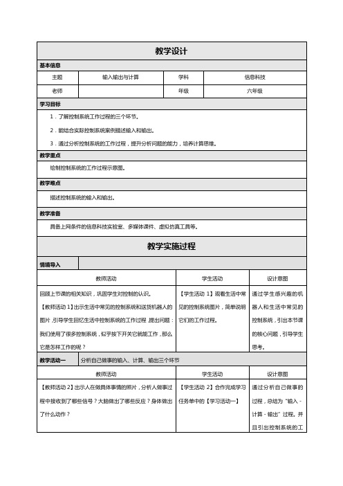
【教师活动3】引导学生分析,发现人做事的过程可以分为
输入、计算、输出三个环节。
【教师活动4】告知学生,控制系统的工作过程也类似:从
外界采集数据(输入)、数据处理)(计算)、产生结果(输
出)。
控制系统的工作过程遵循“输入-计算-输出”的计
算模式。
这个过程中的“计算”,可以理解为人脑进行的思
考、分析、判断等思维活动,也可以看做数据的处理。
【学生活动3】描述声控灯的
工作过程:当声音检测装置检
测到声音时,经过计算生成指
令,灯接收到指令发出亮光或
保持不亮状态。
【学生活动4】完成学习任务
单中的【学习活动二】。
教师引导学生总结知识、分享收获。
【设计意图】让学生通过梳理和总结,巩固本节课所学知识,同时对个人信息保护有进一步的思考。
- 1、下载文档前请自行甄别文档内容的完整性,平台不提供额外的编辑、内容补充、找答案等附加服务。
- 2、"仅部分预览"的文档,不可在线预览部分如存在完整性等问题,可反馈申请退款(可完整预览的文档不适用该条件!)。
- 3、如文档侵犯您的权益,请联系客服反馈,我们会尽快为您处理(人工客服工作时间:9:00-18:30)。
字符型 字符串 指针型
5
第四章 输入输出
常用格式符的注意事项 • 注意"%s"要求对应的输出项为字符串常量(进一步的用法见 第7章数组)。 • printf("%s", "abcd"); • 字符型数据可以用整型格式符;整型数据(0-127)可用%c。 • char c='A'; int i=97; printf("%c %d %c %d", c, c, i, i); • 整型数据可以使用d, o, u, x, i • int a=-1; printf("%d, %o, %u, %x, %i", a, a, a, a, a); -1, 37777777777, 4294967295, ffffffff, -1
scanf("%d %d %c",&x,&y,&ch); //输入:111U222Uy scanf("%d%d%*c%c",&x,&y,&ch); //输入:111U222Uy
21
第四章 输入输出
函数getchar() • 函数getchar()的使用格式:字符变量=getchar( ); • 注意括号中没有参数。
10
第四章 输入输出
函数putchar() • 函数putchar()的使用格式: putchar(一个字符常量或字符变量);
• 一次只能输出一个字符。
• putchar('A'); 等价于 printf("%c", 'A'); • putchar('A'); 等价于 putchar(65);
• char a = 'A'; • putchar(a); //输出字符变量
20
第四章 输入输出
有关格式符的进一步说明 • 例:下面是不同的使用scanf函数输入数据的方法,都使得 x=111,y=222,ch='y'。([CR]表示回车,U表示空格)。
scanf("%d%d%c",&x,&y,&ch); //输入:111U222y
scanf("%d,%d,%c",&x,&y,&ch); //输入:111,222,y
标准输入流
abcd↙
abcd\r
abcd\n
16
第四章 输入输出
有关格式符的进一步说明 • scanf()函数按照"格式控制串"中的内容,在标准输入流中扫 描、匹配或读入相应的数据。凡是已读入的数据都会从标 准输入流中移除。 • 格式控制串中可包括三类内容: • 1)格式符:读入指定类型的数据(读入机制见下页)。 • 2)普通字符:在输入流中匹配相同的字符,若不匹配则 终止scanf()函数。 • 3)空白符(空格、制表符、换行符):一个空白符会匹 配输入流中任意数目(包括0个)的连续空白符,直到下 一个 "非空白符"为止。
12
第四章 输入输出
函数scanf() • 例: • scanf("%d%d", &a, &b); //键盘输入:10 20<回车> 用空白符分隔 • scanf("%d,%d", &a, &b); //键盘输入:10, 20<回车> 用逗号分隔 • scanf("a=%d, b=%d", &a, &b); //键盘输入:a=10, b=20<回车>
9
n
l (小写字母L)
第四章 输入输出
修饰符举例 • • • • printf("%d", 12345); 结果是 12345 。 printf("%6d", 12345); 结果是 U12345 。其中U表示空格。 printf("%-6d", 12345); 结果是 12345U 。 printf("%3d", 12345); 结果是 12345 。
11
第四章 输入输出
函数scanf() • 函数scanf()的使用格式:
scanf("格式控制串", 输入项地址列表);
格式控制串中可以包 含任意字符和格式符 (建议只写格式符) 多个输入项用逗号隔开。 输入项必须是地址!即输 入变量或数组元素时前面 一定要加&符号。
格式符与输入项必须一一对应,尤其注意类型必须一致。 • 简记:格式控制串中有什么则输入什么! 当然,格式符用具体数据输入。
《C语言程序设计》
大连理工大学
第四章
第四章 输入输出
内容提要 • printf() • putchar()
• scanf() • getchar()
2
第四章 输入输出
输入和输出标准库函数 • C语言本身没有输入输出语句。 • 输入和输出的操作由库函数来完成。 • 如:printf( )、scanf( )、 putchar()、getchar()等。 • 这些函数的原型声明在"stdio.h"头文件中。当使用这些函数 时,应在源程序的前面加: #include < stdio.h>。 #include <stdio.h> main() { printf("hello, world"); }
8
第四章 输入输出
修饰符(使用时,放在%和格式符之间) • 一般格式:%[-] [m] [.] [n] [l] 格式符 修饰符 -(减号) 意义
m
数据左对齐(右方补空格), 缺省时右对齐。 域宽,输出数据共占m个字符位。当实际 数据的宽度大于m时,按实际宽度输出。
当输出实数时,表示精度,即有n位小数( 4舍5入); 当输出字符串时,表示取字符串左端n个字 符输出。 用于长整型或双精度型,如:%ld,%lf。
14
第四章 输入输出
scanf函数中常用的格式符 • %后加“*”表示跳过该数据项。 • 如:scanf("%2d,%*3d,%2d", &a, &b); printf("a=%d,b=%d", a, b); 键盘输入:12,345,67<回车> 结果:a=12,b=67。 • 格式控制串的后面不能有“\n”、空格、制表符。 • int a, b; • scanf("%d %d\n", &a, &b); //错。按回车键不会结束。 • 对unsigned型数据,可以用d、o、u、x、i格式输入。
• printf("%f", 123.45); 结果是 123.450000 。 • printf("%-6.1f", 123.45); 结果是 123.5U 。4舍5入 • printf("%.1f", 123.45); 结果是 123.5 。
• printf("%-6s", "abcd"); 结果是 abcdUU 。 • printf("%.2s", "abcd"); 结果是 ab 。
19
第四章 输入输出
有关格式符的进一步说明 • 例:下面的scanf函数输入数据,使得 i=10,j=15,c1='S',c2='s',x=1.5,y=-3.75,z=67.8,写出正确的键 盘输入方法。([CR]表示回车,U表示空格)。
main() {int i,j; float x,y,z; char c1,c2; scanf("%5d%5d%c%c%f%f%*f%f", &i, &j, &c1, &c2, &x, &y, &z); printf("%5d,%5d,%c,%c,%f,%f,%f", i, j, c1, c2, x, y, z);} 键盘输入: 10UUU15Ss1.5U-3.75U123.5U67.8[CR]
7
第四章 输入输出
常用格式符的注意事项 • 在格式控制串中写两个百分号"%%"用于输出一个百分号。 • float k=0.56789;printf("%4.1f%%",k*100); //56.8%
• 若%后跟一个非格式符,则只输出这个非格式符。如%K只打 印出K。(不要这样使用) • printf("%d%K",100); //100K
• 一次只能输入一个字符。
• char a; • a=getchar(); 等价于 scanf("%c", &a);
22
123.625
• 对不同类型的数据应使用不同的格式符。
• 输出项为实型时,只能用e, f, g;不能用douxi。 • 输出项为整型时,不能用e, f, g;否则出错。
printf("%d", 2.5); printf("%f", 123); //都是错误的 double a=2.0; printf("%d,%lf,%le,%lg", a,a,a,a); //试一下
3
第四章 输入输出
函数printf( ) • 函数printf()的使用格式:
printf("格式控制串", 输出列表);
格式控制串中可 以包含任意字符 和格式符 输出列表可以是常量、变 量、表达式等,多个输出 项用逗号隔开
格式符与输出项必须一一对应,尤其注意类型必须兼容。 • 简记:格式控制串中有什么则输出什么! 当然,格式符用输出项内容替换。
