F2X46-D电力级嵌入式IP Modem说明书V1.0.0
奥德维特说明书

PDA 系列产品的设计、制造、检查、试验及特性都应遵照适合的最新版IEC 和中国GB 标准及国际单位SI 制。
GB/T13730《地区电网数据采集与监控系统通用技术条件》GB/50171-92《电气装置安装工作盘、柜及二次回路接线施工及验收规范》DL/T630《交流采样远动终端通用技术条件》DL/478-92《静态继电保护及安全自动装置通用技术条件》GB/50062-92《电力装置的继电保护和自动装置设计规范》GB/T50063-2008《电力装置的电测量仪表装置设计规范》DL/T587-1996《微机继电保护装置运行管理规程》GB/T13729-2002《远动终端通用技术条件》GB/14285-93《继电保护和安全自动装置技术规程》GB/T17626.12-1998《振荡波抗扰度试验》GB/T17626.11-2008《电压暂降、短时中断和电压变化抗扰度试验》GB/T17626.10-1998《阻尼振荡磁场抗扰度试验》GB/T17626.8-2006《工频磁场的抗扰度试验》GB/T17626.6-2008《射频场感应的传导骚扰抗扰度》GB/T17626.5-2008《浪涌(冲击)抗扰度试验》GB/T17626.4-2008《电快速瞬变脉冲群抗扰度试验》GB/T17626.2-2006《静电放电抗扰度试验》GB/T 14047-1993《量度继电器和保护装置》GB 3836.3-2000《爆炸性气体环境用电气设备 第 3 部 分:增安型"e"》JB/T 10613-2006《数字式电动机综合保护装置》GB/T13850-1998《交流电量转换为模拟量或数字信号的电测量变送器》JJG596-1999《电子式电能表检定规程》GB/T17215.321-2008《静止式有功电能表(1级和2级)》GB/T 22264-2008《安装式数字显示电测量仪表》产品标准Contents 目 录A -01综合电力监控仪PDA-120系列B -13 三相智能型电力仪表 PDA-103系列C -31单相智能型电力仪表 PDA-101系列D -51 智能型电动机保护控制器 PDA-110MRK F -66参考设计图附录产品业绩G -73GB/T17215.322-2008《》静止式有功电能表(0.2S 级和0.5S 级)E -58 低压电动机保护装置 ADVP-1451产品简介功能详表产品特点PDA -120系列综合电力监控仪是北京奥德威特电力科技股份有限公司按IEC 国际标准开发,与当今国际先进技术同步的网络化综合电力监控仪表。
三汇示波器说明书(Ver1.0)
DST4000 和 DST1000 系列数字存储示波器用户手册
i
目录
5.1 显示区 ........................................................................................ 20 5.2 信息区域..................................................................................... 23 5.3 波形显示..................................................................................... 23
三汇系列产品
DST4000 和 DST1000 系列 数字存储示波器
Version 1.0
杭州三汇科技有限公司 www.
目录
目录
目 录 ...........................................................................................................i 版权申明 .......................................................................................................................................................................v 第 1 章 安全事项......................................................................................... 1
KD600配电自动化系统馈线远方终端(FTU)技术说明书V1[1].00学习资料
![KD600配电自动化系统馈线远方终端(FTU)技术说明书V1[1].00学习资料](https://img.taocdn.com/s3/m/e3933550650e52ea54189827.png)
K D600配电自动化系统馈线远方终端(F T U)技术说明书V1[1].00精品文档目录一、概述 (4)二、主要性能特点: (4)三、引用标准 (5)四、主要技术指标 (6)五、主要功能 (7)六、硬件结构 (8)七、显示操作 (11)八、端子图 (16)本说明书仅适用于KD600配电自动化系统馈线远方终端。
请仔细阅读本说明书,并按照说明书的规定调整、测试和操作。
如有随机资料,请以随机资料为准。
一、概述KD600配电自动化系统远方终端是按照配网自动化的需求,配电网自动化系统,实现35kV以下配变变电站、开闭所、开关房等电压、电流、开关状态、温度等的实时采集、上送以及对开关的远程分合控制。
它结合中国配电网的运行状况,吸收了国际上配网自动化的先进技术和青岛科电电气公司多年从事配网自动化的工作经验开发而成。
KD600配电自动化系统远方终端采用高性能32位的ARM微处理器、嵌入式实时操作系统,全部采用工业级器件,具有功能强大,处理速度快,运行稳定可靠等优点。
装置采用插箱结构,模块组态灵活,扩展方便,能够实现各种监控容量的配置要求,最大限度地满足用户的实际需求。
KD600配电自动化系统远方终端提供双以太网通讯方式,同时具备2路RS485串行通讯方式,并且可扩展配置GPRS通讯方式,该装置与主站配合,完成对多条配电线路的各种监控功能、DA功能。
二、主要性能特点:●采用ARM硬件平台的实时多任务嵌入式操作系统。
●插板式结构,功能插板种类丰富,组态配置灵活,支持插件热插拔功能。
●与外联系的部分均采用信号隔离措施——如,电源隔离、电磁隔离、光电隔离等,以提高装置的抗干扰能力。
●全面的自检、互检及错误报警功能●支持远程维护,可远程查看运行数据、上下装程序和参数●安全可靠的遥控输出控制,采用了多项防“误动”技术:节点反校、长密码锁控制、负电压驱动技术。
●主体器件采用高可靠性工业级器件,采用自动监测、补偿技术提高硬件电路稳定性、可靠性。
F2X46-DK 系列使用说明书
F2X46-DK系列使用说明书文档版本密级V2.0.0产品名称:F2X46-DK共29页F2X46-DK系列使用说明书此说明书适用于下列型号产品:型号产品类别F2446-DK WCDMA电力级IP MODEMF2646-DK EVDO电力级IP MODEMF2746-DK TDD-LTE电力级IP MODEMF2846-DK FDD-LTE电力级IP MODEMF2A46-DK LTE电力级IP MODEM厦门四信通信科技有限公司Add:厦门市集美区软件园三期诚毅大街370号A06栋11层客户热线:400-8838-199电话:+86-592-6300320传真:+86-592-5912735网址文档修订记录日期版本说明作者2016.8.25V1.0.0初建Faine 2017.9.23V2.0.0更新地址Faine著作权声明本文档所载的所有材料或内容受版权法的保护,所有版权由厦门四信通信科技有限公司拥有,但注明引用其他方的内容除外。
未经四信公司书面许可,任何人不得将本文档上的任何内容以任何方式进行复制、经销、翻印、连接、传送等任何商业目的的使用,但对于非商业目的的、个人使用的下载或打印(条件是不得修改,且须保留该材料中的版权说明或其他所有权的说明)除外。
商标声明Four-Faith 、四信、、、均系厦门四信通信科技有限公司注册商标,未经事先书面许可,任何人不得以任何方式使用四信名称及四信的商标、标记。
产品外形图注:不同型号配件和接口可能存在差异,具体以实物为准。
目录第一章产品简介 (7)1.1产品概述 (7)1.2产品特点 (7)1.3产品规格 (8)第二章安装 (11)2.1概述 (11)2.2开箱 (11)2.3安装与电缆连接 (11)2.4电源说明 (14)2.5指示灯说明 (14)第三章参数设置 (15)3.1界面说明 (15)3.2配置选项说明 (16)3.2.1“本地串口设置”项: (16)3.2.2“本地串口2设置”项: (16)3.2.3“DTU工作模式设置”项: (17)3.2.4“GPRS拨号参数设置”项及“GPRS2拨号参数设置”: (17)3.2.5“支撑平台相关设置”项: (17)3.2.6“企业网关相关设置”项: (18)3.2.7“多IP数据中心”项: (18)3.2.8“多连接策略”项: (18)3.2.9“其他配置”项: (18)3.2.10“网管平台相关设置”项: (18)3.2.11“管理员登录设置”项: (19)3.2.12“ICMP参数设置”项: (19)3.2.13“自定义UDP帧格式”项: (19)3.3读写配置 (19)3.4修改配置 (21)第四章使用说明 (22)4.1工作模式使用说明 (22)4.1.1DC模式 (22)4.1.2透传模式 (22)4.2连接方式使用说明 (22)4.2.1长连接方式 (22)4.2.2短连接方式 (23)4.3查看系统及连接状态 (23)4.4远程升级的使用说明 (24)4.5本地串口升级 (24)第五章测试 (26)5.1DC测试 (26)5.1.1DCUDP模式 (26)5.1.2DCTCP模式测试 (29)附录一常见问题 (30)第一章产品简介1.1产品概述F2X46-DK系列电力级IP Modem是一种物联网无线数据终端,利用WCDMA/EVDO/ TDD-LTE/FDD-LTE网络为用户提供无线数据传输功能。
数字电视网络工程测量仪器手册 2012 Ver1.0

电 视
通用型测试仪器
和 广
E8000A 手持频谱分析仪----------------------------------------------------------------- 67
播
E7000A 手持天馈线测试仪----------------------------------------------------------------71
字 电
DS2100Q/B 经济型数字电视测试仪--------------------------------------------------------- 41
视 综
DS9000-I 便携式码流分析仪-------------------------------------------------------------- 43
(一)双向网络监测系统
双
ห้องสมุดไป่ตู้
DS1610 “鹰视通”宽带网络监测系统------------------------------------------------------- 3
向
DS1600 安播质量监测系统--------------------------------------------------------------- 10
AE100A/AE100B/AE120/AE160 迷你型光功率计----------------------------------------------- 87
模
AE200A/AE200B/AE220/AE260 光功率计---------------------------------------------------- 88
DS2002H 手持普及型场强仪-------------------------------------------------------------- 91
20100315电力载波透传嵌入式模块(DrF-2201)说明

电力线载波通信透明传输嵌入式模块 (型号:DrF-2201)说明书北京博创汉威科技有限责任公司Beijing DrFound Tech. Corp.By James Shen2010-1采用以色列Yitran公司IT700电力线载波芯片技术;DCSK扩频调制和Y-NET自动组网技术,超强的电力线通信性能;开放的接口,实现数据在电力线网络中的透明传输,支持各种协议,如Modbus等;使用方便,嵌入式设计,透明传输接口缩短客户载波通信设备开发周期。
电力线载波通信透明传输嵌入式模块DrF-2201 可以于用户开发的设备相结合,使用户设备具备电力线通信功能。
DrF-2201 可广泛应用于工业控制、电力抄表、路灯监控、道路交通、安防监控等行业。
技术参数基本参数♦供电: +3.3V/600mA♦数据接口:串口 RX/TX♦波特率:9600bps(默认)♦数据位:8位♦结束位:1位♦奇偶校验:无♦工作温度:-25℃ ~ +70℃♦尺寸:57mmx59mmx18mm♦调制方式:DCSK( Yitran专利技术)♦载波频率:100kHz~400kHz(可选)♦数据传输率:7.5kbps,5kbps,1.25kpbs(自适应)♦自动中继:7级♦自动组网:Y-NET♦支持PLC标准:CB/FCC/ARIB配置♦计算机串口配置:配置软件♦本地拨码开关配置稳定性♦主CPU:ARM ♦内置看门狗接口♦双排插针 P6,P7状态指示♦LED状态显示¾模块上线LED1亮¾数据发送LED2闪¾数据接收LED3闪实物说明用户接口P6: 2X4 接口定义8. LINE1 信号耦合端 7. LINE2 信号耦合端 6. LINKLED 上线指示灯信号 5. TXLED 发送指示灯信号 4. GND 地 3. RXLED 接收指示灯信号 2. 3.3V 电源 1. 3.3V 电源P7: 2X4 接口定义8. GND 地 7. GND 地6. UART2_TX 串口2发送 5. UART2_RX 串口2接收 4. GND 地 3. GND 地 2. UART1_TX 串口1 发送 1. UART1_RX 串口1 接收注:其中UART1用于计算机参数配置,UART2用于信号透明传输接口尺寸用户开发的电路板上按照DrF-2201的尺寸和插针P6,P7位置预留接口(2X4插座),按照接口定义实现接线,如下图所示,用户提供的接口线路信号分成4类:电源信号: 3.3V ,GND串口通信接口: UART2_RX/ UART2_TX 参数设置参见上表 串口配置接口: UART1_RX/ UART1_TX 参数设置参见上表载波耦合信号: LINE1/LINE2耦合电路模块配置配置方式一: 计算机串口配置 UART1 (拨码开关START=OFF)通讯设置:启动软件,点击“通信设置”按钮,设置计算机串口属性,保证计算机和模块的正常通信,以完成配置和测试,设置计算机串口通信参数如下:串口号:com1(视实际情况而定),波特率:9600(默认初始值),数据位:8,停止位:1,奇偶校验:无,流控:无。
PCS-9616D_X_说明书_国内中文_国内标准版_X_R1.30
外部回路 当把装置输出的接点连接到外部回路时,须仔细检查所用的外部电源电压,以防止所连接的回
路过热。 连接电缆
仔细处理连接的电缆避免施加过大的外力。
版权声明 © 2015 NR. 南京南瑞继保电气有限公司版权所有
警告!
为增强或修改现有功能,装置的软硬件均可能升级,请确认此版本使用手册和您购买的产品相 兼容。
警告!
电气设备在运行时,这些装置的某些部件可能带有高压。不正确的操作可能导致严重的人身伤 害或设备损坏。
只有具备资质的合格专业工作人员才允许对装置或在装置临近工作。工作人员需熟知本手册中 所提到的注意事项和工作流程,以及安全规定。
1.1 应用范围 ............................................................................................................................. 1 1.2 功能配置 ............................................................................................................................. 1 1.3 性能特征 ............................................................................................................................. 2 1.4 订货须知 ............................................................................................................................. 3 1.5 产品执行标准...................................................................................................................... 3 第 2 章 技术参数 .............................................................................................................................. 5 2.1 电气参数 ............................................................................................................................. 5 2.2 机械结构 ............................................................................................................................. 6 2.3 环境条件参数...................................................................................................................... 7 2.4 通信端口 ............................................................................................................................. 7 2.5 型式试验 ............................................................................................................................. 8 2.6 认证 .................................................................................................................................... 8 2.7 保护功能 ............................................................................................................................. 9 2.8 管理功能 ............................................................................................................................. 9 第 3 章 工作原理 .............................................................................................................................11 3.1 概述 ...................................................................................................................................11 3.2 装置启动元件.....................................................................................................................11 3.3 (短充)过流保护和零序保护 .......................................................................................... 12 3.4 (长充)过流保护和零序保护 .......................................................................................... 13 3.5 同期功能(可选) ............................................................................................................ 14 3.6 异常告警 ........................................................................................................................... 15 3.7 采样数据异常的处理......................................................................................................... 16 3.8 遥控、遥测、遥信功能 ..................................................................................................... 16 3.9 时间管理 ........................................................................................................................... 16 第 4 章 硬件描述 ............................................................................................................................ 19
XPT2046电阻式触摸屏控制器 说明书

8.3
内部参考电压 ................................................................................................................................. 14
8.4
外部参考电压输入 ......................................................................................................................... 14
2 主要特性 ........................................................................................................................................................... 4
8.5
单端工作模式 ................................................................................................................................. 15
8.6
差分工作模式 ..........................................................................................................................模式 .................................................................................................................................. 22
嵌入式安装式电表说明书
光耦隔离,集电极开路输出
RS485, MODBUS-RTU/DLT645-2007(其他协议可定制)
≤0.5s/d
室内型工作温度:-10℃~+45℃
户外型工作温度:-25℃~+55℃
宽温型工作温度:-40℃~+70℃
存储温度:-40℃~+70℃
≤95%(无凝露)
72×72×74(mm)(不含接线端子)
3. 技术参数
项目 精度等级 计量额定电压 计量电流规格 辅助工作电源
技术指标 有功:0.2/0.5/1 级 无功:2 级 3×220/380V ;3×57.7/100V
1.5(6) A,5(6)A,5(20) A,10(40) A,20(80) A 正常工作电压范围:0.7~1.4Un
参比频率 起动电流
DT(S)SD178/ 179 三相多功能电能表
DONGFANG.WISDOM
DT(S)SD178/ 179
嵌入式三相多功能电能表
用户手册
烟台东方威思顿电气有限公司
I
DT(S)SD178/ 179 三相多功能电能表
II
DT(S)SD178/ 179 三相多功能电能表
目录
1. 概述...................................................................................................................................................................... - 4 2. 产品规格.............................................................................................................................................................. - 4 3. 技术参数.............................................................................................................................................................. - 4 4. 安装与接线.......................................................................................................................................................... - 5 -
IPEVD 安装指南说明书

Step-by-step guide to setting up IPEVO document cameras with Microsoft TeamsTip:Some 3rd party software may default to a mirror image on your end while showing the correct orientation on the other end when you're using a document camera with it. This is a default setting of the 3rd party software. To get the image showing up in the correct orientation on your end, either use the native Mirror feature of the software or stream your live feed through the IPEVO Visualizer software and then share it via the screen sharing feature of the 3rd party software.Setting up IPEVO document cameras with Microsoft TeamsList of materials neededBefore you start, make sure you have the following on hand:An IPEVO document cameraA computerMicrosoft TeamsIPEVO Visualizer software (for screen sharing)Step-by-step guideHere are the steps to setting up your IPEVO document camera with Microsoft Teams.1. Plug in an IPEVO document camera to your computer via USB. Remember to turn it on if you’re using a VZ-R or VZ-X.2. Open Microsoft Teams on your computer and sign in with your username and password. Create an account if you don’t have one. Follow the steps outlined here to sign up for one.3. Click your profile picture, and click Settings in the drop-down list to open the settings page.4. On the settings page, click the Devices tab.5. Select your IPEVO document camera as the video source in Camera.6. If you’d like to access the built-in microphone of your IPEVO document camera, change your audio source in Microphone as well.7. As with other third-party software that sets their default image to be mirrored, you’ll see a mirrored image in your preview when you use your IPEVO document camera with Microsoft Teams. To get around this, simply use the Share function in Microsoft Teams.(1) Stop the Teams software from accessing your IPEVO document camera by switching the video source.(2) Download and run the free IPEVO Visualizer software to stream the live images of your IPEVO document camera. You can download IPEVO Visualizer here.(3) Go back to the Teams software, and click the Share function to start sharing your screen.(4) You may choose to share a selected window or the whole desktop.(5) Now the image you’re seeing will be in the correct orientation.8. Make use of IPEVO document cameras’ multi-joint stands and swiveling camera heads to capture your materials at the height, angle, and orientation that best fit your needs. If you’re using VZ-R or VZ-X, you can even adjust the images at your fingertips with the available tactile buttons!。
洛雷技术IP球机说明书
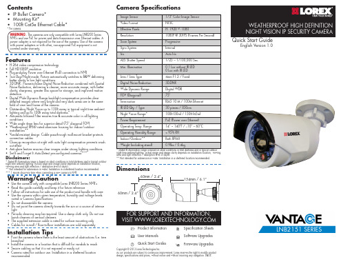
• IP Bullet Camera* • Mounting Kit* • 100ft Cat5e Ethernet Cable*
* Per camera.
WARNING - The cameras are only compatible with Lorex LNR200 Series NVR’s and use PoE for power and data transmission over Ethernet cables. A power adapter is not required for the use of the camera. Use of the camera with power adapters or with other, non-approved PoE equipment is not covered under warranty.
Before installing the camera:
• Decide whether to run the cables through the wall / ceiling (drilling required) or along the wall / ceiling.
recommended
Camera Specifications
Image Sensor
1/3” Color Image Sensor
Video Format
NTSC
Effective Pixels
H: 1920 V: 1080
Resolution
1080P @ 30FPS (Frames Per Second)
Features
• H.264 video compression technology • Full HD1080P resolution • Plug-and-play Power over Ethernet (PoE) connection to NVR • True Day/Night mode: Picture automatically switches to B&W delivering
F200说明书

安装指南
型号:F200
neidnl [选取日期]
炥莱茵科技有限公司
目录
炥莱茵科技有限公司
一、产品概述及功能简介 ......................................................................................................................2 二、技术指标.........................................................................................................................................3 三﹑包装清单.........................................................................................................................................3
用 户 手 册(V10)

公司产品主要有 10Mbps 高速电力调制解调器、高速电力路由器、高速电力桥集器; 50Mbps 高速电力调制解调器、高速电力桥集器;85Mbps 高速电力调制解调器、高速电力桥 集器;224Mbps 高速电力调制解调器、高速电力桥集器;家庭自动化系统、网络抄表系统等 系列产品。
亿力网络拥有一支高素质的技术和管理专业队伍,现有职工中大专以上学历的员工占职 工总数的 70%以上。
包装清单
安装使用前请检查包装盒中的物品,应包括以下物件:
一台 FPM-224M 高速电力调制解调器主机 一条直连网线 一条直连双头三芯电源线 一本用户手册 一张产品保修卡 一张产品合格证
注意:拆包后如有物件不全或者损坏,请及时与福建省亿力电力网络信息设备有限公司或当 地供应商联系,以便更换。
亿力网络的经营方针为致力于配合国家电力信息产业发展的战略规划,专业提供高质量 的工业和民用电力线网络通信设备,以努力满足社会网络信息化不断发展的要求。
产品简介
感谢您使用亿力网络公司的高速电力调制解调器及其它产品。 FPM-224M 高速电力调制解调器是本公司推出的计算机网络应用产品,可通过电力线在 224Mbps 通信速率上连接宽带网络。“电线上网”是一种全新的“宽带”上网方式,只用一 台电脑、一个高速电力调制解调器,利用任何一个普通的 220V 电源插座,不用布建任何网 络线路,也不需要占用电话线路,点击浏览器就可以上网遨游了。上网速度可与一般的“宽 带”网络相媲美。使得用户享受了宽带的高速便捷,又免去了破坏环境,维护困难的苦恼。 可广泛应用于个人用户、小型办公司系统、校园网络、社区网络、酒店宾馆等。 本公司应用创新技术自行研制的电力线上网技术,全面解决了电力线通信领域长期存在 的不稳定和不安全问题。设计兼容目前的 Windows98/ME/2000/XP 操作系统,用户只要经过 简单的设置,即能通过电力线上网或组成自己的局域网,在使用的灵活性上更胜一筹。利用 电力线上网,网络资源丰富、施工方便、一线两用、价格低廉等。电力线上网不仅为广计算 机网络用户提供了一个新的选择,而且也必然推动整个宽带服务行业的发展与繁荣。
博世FlexiDomeDN IP网络摄像头操作指南说明书
55
7.7.1
iSCSI IP address (iSCSI IP 地址)
55
7.7.2
iSCSI LUN map (iSCSI LUN 映射)
55
7.7.3
Target IP address (目标 IP 地址)
56
7.7.4
Target node (目标节点)
56
7.7.5
Target LUN (目标 LUN)
56
7.7.6
Target password (目标密码)
56
7.7.7
Initiator name (启动程序名称)
56
7.7.8
Initiator extension (启动程序扩展)
56
7.7.9
Decoupling the drive used (断开使用的驱动器)
57
7.7.10 Storage information (存储信息)
4
摄像机设置
4.1
摄像机定位
4.2
焦距和焦点
4.3
基本设置
博世安保有限公司
操作指南
| 中文 3
13 14 14 15 15 15 16 16 16 16 16 16 16 17 17 17 17 17 17
18
19 20 20 20 21 21
22 22 23 23
V 1.0 | 2006.12
4 中文 |
74
7.13.6 Send e-mail for testing (发送电子邮件进行测试)
74
7.14
Service Settings (服务设置)
74
7.14.1 Network (网络)
AD7028电力级嵌入式IP MODEM使用手册说明书

AD7028电力级嵌入式IP MODEM使用手册支持2G/3G/4G功能的电力级嵌入式数据传输终端适用机型:厦门爱陆通通信科技有限公司热线:400-808-5829电话:传真:网址:地址:厦门市集美区杏北二路146-148号目录AD7028电力级嵌入式IP MODEM使用手册 (1)目录 (3)第1章产品简介 (5)1.1 产品概述 (5)1.2 产品特点 (5)1.3 工作原理框图 (6)1.4 产品规格 (7)1.5 订购信息 (8)第2章产品安装 (9)2.1 概述 (9)2.2 装箱清单 (9)2.3 产品尺寸 (9)2.4 电源说明 (12)2.5指示灯说明 (12)2.6 复位按钮说明 (13)第3章参数配置 (14)3.1 设备与PC连接图 (14)3.2 登录到配置页面 (14)3.2.1 PC机IP地址设置(两种方式) (14)3.2.2 登录到配置界面 (15)3.3 网络基本 (16)3.3.1 广域网 (16)3.3.2 广域网状态 (19)3.3.3 局域网 (19)3.3.4 局域网状态 (21)3.4 网络高级 (22)3.4.1 静态地址分配 (22)3.4.2 高级路由 (22)3.4.3 MAC地址克隆 (23)3.4.4 静态域名解析 (23)3.5 无线设置 (23)3.5.1 基本设置 (23)3.5.2 无线安全 (24)3.5.3 无线状态 (25)3.6 VPN (26)3.6.1 PPTP (26)3.6.2 L2TP (27)3.6.3 IPSEC (27)3.6.4 GRE (28)3.7 安全 (29)3.7.1 防火墙 (29)3.7.2 访问限制 (30)3.7.3 MAC过滤 (32)3.7.4 数据流过滤 (32)3.8 转发规则 (33)3.8.1 端口转发 (33)3.8.2 端口范围转发 (34)3.8.3 端口触发 (34)3.8.4 DMZ服务 (34)3.9 带宽服务 (35)3.9.1 流量监控 (35)3.10 物联互通 (35)3.10.1 串口应用 (35)3.10.2 短信控制 (37)3.11 系统设置 (37)3.11.1 快捷按钮 (37)3.11.2 密码管理 (37)3.11.3 设备管理 (37)3.11.4 系统时间 (39)3.11.5 重启IP Modem (39)3.11.6 配置管理 (39)3.11.7 软件升级 (40)3.11.8 DDNS (40)3.11.9 系统日志 (41)第1章产品简介1.1 产品概述AD7028 电力级嵌入式IP MODEM是基于2G/3G/4G等技术开发的物联网无线数据传输终端。
ES46xx 嵌入式影像扫描器 用户手册说明书
ES46xx嵌入式影像扫描器用户手册版本:ES46xx_UM_CN_V2.1.2目录1 参数 (1)1-1 技术参数-ES4600 (1)1-2 技术参数-ES4620 (3)1-3 条码预设参数 (5)2 开始使用 (6)2-1 部件说明-ES4600 (6)2-2 部件说明-ES4620 (6)2-3 线缆连接头引脚定义 (7)2-4 典型输入/输出特性与供电电路 (9)2-5 电源管理 (10)2-6 安装设计 (11)2-6-1 装配尺寸图-ES4600 (11)2-6-2 装配尺寸图-ES4620 (12)2-6-3 扫描窗位置-ES4600 (13)2-6-4 扫描窗位置-ES4620 (14)2-6-5 照明发散角与扫描成像角-ES4600 (15)2-6-6 照明发散角与扫描成像角-ES4620 (17)2-7 时序 (19)2-7-1 时序特性 (19)2-7-2 时序图 (19)2-8 操作示例 (20)2-8-1 时序特性 (20)2-8-2 请求版本信息 (20)2-8-3 置低TRIG引脚后开始解码 (20)2-8-4 发送命令后开始解码 (21)3 参数菜单 (22)3-1 简介 (22)3-2 示例1:扫描一维条码完成单一参数设置 (23)3-3 示例2:扫描QR码完成多参数设置 (24)3-4 RS-232接口 (25)3-5 USB接口 (27)3-6 扫描模式与部分全局设置 (29)3-7 LED指示与蜂鸣器提示 (33)3-8 解码照明与解码瞄准设置 (34)3-9 单一码种、同图多条码与垂直居中识读 (35)3-10 DPM码、结构链接与手机屏识读 (38)3-12 UPC-E (42)3-13 UPC-E1 (44)3-14 EAN-13 (46)3-15 EAN-8 (48)3-16 39码(32码,Trioptic 39码) (50)3-17 交叉25码 (53)3-18 工业25码 (55)3-19 矩阵25码 (56)3-20 库德巴码 (57)3-21 128码 (59)3-22 UCC/EAN 128(GS1-128) (61)3-23 ISBT 128 (63)3-24 93码 (64)3-25 11码 (65)3-26 MSI/Plessey (66)3-27 UK/Plessey (68)3-28 中国邮政码 (69)3-29 中国财政码 (70)3-30 Telepen (72)3-31 GS1 DataBar(GS1 DataBar Truncated) (74)3-32 GS1 DataBar Limited (75)3-33 GS1 DataBar Expanded (76)3-34 GS1 Composite(GS1复合码) (77)3-35 PDF417 (79)3-36 MicroPDF417 (80)3-37 QR码 (81)3-38 Data Matrix (82)3-39 汉信码 (83)3-40 Aztec码 (84)3-41 MicroQR码 (85)3-42 CodaBlock F码 (86)3-43 GM码 (87)3-44 G1-G6、C1-C2与FN1替换字符串设置 (88)3-45 符串插入位置与码制识别符位置 (92)3-46 字符串传送 (93)4 使用SCI完成参数设置 (95)4-1 参数设置命令格式 (96)4-1-2 多参数设置 (96)4-1-3 参数查询 (97)4-1-4 开始解码与结束解码 (97)4-1-5 恢复出厂设置与版本信息显示 (97)4-1-6 图像获取 (97)4-1-7 命令回应 (98)4-2 SCI使用示例 (99)5 使能/禁止“NR”功能 (100)6 使能/禁止通过扫描条码完成参数设置 (101)7 非打印字符条码表 (102)8 ASCII表 (103)9 测试条码图样 (104)10 恢复出厂设置与版本信息显示 (109)11 设置选项参数条码 (110)注意事项1.嵌入式扫描器外壳必须电气隔离。
Eaton电子有限公司SD范围 surge保护设备说明书
Eaton Electric Limited,Great Marlings, Butterfield, Luton Beds, LU2 8DL, UK.Tel: + 44 (0)1582 723633 Fax: + 44 (0)1582 422283E-mail:********************© 2022 EatonAll Rights ReservedPublication No. EPS 901-107 Rev W October 2022The SD range is a series of surge protection devices combine unparalleled packing densities, application versatility, proven reliable hybrid circuitry, simple installation and optional ‘loopdisconnect’ facilities – features which make the range the ultimate surge protection solution for process equipment, I/O systems and communications networks.The exceptionally high packing densities are the consequence of an ultra slim ‘footprint’ for individual modules which can thus ‘double-up’ as feedback terminals. Each module provides full hybrid surge protection for 2 and 3 wire loop protection.Modules with a comprehensive range of voltage ratings cover all process related signals such as RTDs, THCs, 4 to 20mA loops, telemetry outstations, shut-down systems and fire and gas detectors.Optional ‘loop disconnect’, is a feature which allowscommissioning and maintenance to be carried out withoutremoval of the surge protection device. This facility is provided by the SD07, SD16, SD32 and SD55 units. In addition, a thirdconnection on the field and safe side of the protector is provided in order to terminate screens safely.MTL SD rangeUltra-slim user-friendly devices for protecting electronic equipmentand systems against surges on signal and I/O cabling.For three wire applications the specially designed SDRTD(Resistance Temperature Detector) and the SD32T3, (for separately powered 4-20mA loops) provide full 3-wire protection in a single compact unit. The recommended choice for the protection of 3-wire pressure transducers on low power circuits is the SD07R3.For higher bandwidth applications , the SDR range has been developed to meet the demands of today’s highest speed communication systems.120V and 240V AC versions are available for I/O and powersupplies up to three Amps of load current and telephone networks can be protected by the SDPSTN.One simple manual operation clamps modules securely onto DIN rail, which automatically provides the essential high-integrity earth connection.‘T op-hat’ (T -section) DIN rail is generally suitable for mounting SD modules although for adverse environments, a specially-plated version is available. A comprehensive range of mounting and earthing accessories can also be supplied, see page 7 for further details.• Range of ATEX Certified intrinsically safe surge protectors• Ultra-slim space-saving design; easy installation• Multistage hybrid protection circuitry – 20kA maximum surge current• Range of voltage ratings – to suit all process I/O applications• High bandwidth, low resistance, RTD, PSTN and 3-wire transmitter versions available • 10 year product warrantyGuide to applications and selectionThe SD range of SPDs includes models for almost all possible applications operating at voltages up to 250V AC. The optional ‘fuse/disconnect’ package provides both fused protection against fault currents and a convenient method of isolating field circuitry from protected circuitry without needing additional disconnect terminals. The standard fuse (which is replaceable) is rated250mA with 50mA fuses also being available by special request. Where only the disconnect feature is required, solid links can be used.As an example, this feature is of particular value in applications in which an SPD is used with a bulk power supply feedingmultiple loops. The individual module fuse prevents a fault or follow on current on one loop disrupting the power supply to the others. Also, loops can be removed from the circuit for maintenance reasons or added without needing additional disconnect terminals.The following guide to selection suggests the most suitable SDs for a number of specific applications. For technicalinformation, see the detailed specifications on the back page of this publication (some field circuit protection is shown for completeness).FIELD CIRCUIT PROTECTED CIRCUIT2-wire transmitters3-wire RTDsPhotocells, THCs, mV sources and turbine flowmetersAnalogue inputs (high-level)2-wire transmitters, 4-20mA, conventional and smartThe SPDs recommended for use with ‘conventional’ and ‘smart’ 4-20mAtransmitters (fed by a well-regulated supply) are the SD32 and SD55, the choice depending upon the maximum working voltage of the system (32V and 55V respectively). The diagram illustrates a prime example of an application for which the fuse/disconnect facility is particularly useful, however, both models are available in ‘X’ versions without the optional fuse/disconnect feature.Analogue inputs (low-level)RTDsThese applications are best served using the SDRTD. For optimum accuracy, the energising current should be chosen to ensure the voltage across the RTD does not exceed 1V over the full measurement range. When using a PT100 device, we recommend an energising current of 1mA.Photocells, THCs, mV sources and turbine flowmetersThe SD07 or SD16 (depending upon theoperational voltage) are the favoured choices for this application. SD07X and SD16X are also suitable.FIELD CIRCUITPROTECTED CIRCUITController outputs (I/P converters)SwitchesAlarms, LEDs, solenoid values, etc.T elecom linePLC, I/O systemsAnalogue outputsController outputs (I/P converters)For this application, the recommendations are the SD16, SD32 and SD55 (and the equivalent ‘X’ versions), the final choice depending upon the operating voltage.Digital (on/off) inputsSwitchesSuitable SPDs for switches include the SD07, SD16, SD32 and SD55 modules – the choice depending upon the operating voltage of the system. T he ‘X’ versions of these are also suitable.Digital (on/off) outputsAlarms, LEDs, solenoid valves, etcAlarms, LEDs, solenoid valves, etcThe recommended choice for this application is the SD32 or SD32X.T elemetry (PSTN)Telemetry outstationsThe SDPSTN has been designed specifically for the protection of signals transmitted on public switched telephone networks.AC supplied equipmentPLC, I/O systemsFor systems on 110-120V ac, the SD150X is the recommended choice and for 220-240V ac systems, the SD275X is recommended.T ransmitter and sensor protectionTransmitters and sensors are widely used in highly exposed areas and where lightning damage is common. In many cases, the ideal solution for 2-wire transmitters or sensors is the TP48 which mounts directly onto the transmitter housing via spare cable entries. Where these entries are not available or 3-wire devices are used, the compact design and simple installation of the SD range makes it the obvious choice for transmitter protection.The SDs within the junction box should be installed no further than one metre away but as close as possible to the sensor or transmitter they are protecting. A bond is required from the general mass of steelwork to the sensor or transmitter housing either using a flat short braid or a cable of at least 4mm2 cross sectional area. In most instances this bond is automatically made by fixing the metallic transmitter housing to the plant structure. This bond ensures the voltage difference between the signal conductors and the transmitter housing is below the transmitter’s insulation rating. Please note that the transmitters or sensors are connected to the ‘Protected Equipment’ terminals of the SD and not the ‘Field Cables’.2-wire transmitter or sensor 3-wire transmitter or sensor 4-wire transmitter or sensor TO HOST CIRCUITSD PROTECTED FIELD CIRCUIT 2-wire transmitters or sensors4-20mA transmitters, conventional and smartWhere the TP48 is not an acceptable solution,either because of technical suitability ordifficulties in mounting, the SD16X, SD32Xand SD55X are an excellent alternative.3-wire transmitters or sensorsVibration Sensors and 4-20mA loop processcontrol systems invariably require threewire connections, when powered from anexternal source.This may be accomplished in one unit byusing the SD32T3 three terminal SurgeProtection Device (SPD).Because the SD32T3 protects all threeconductors within the same unit, higherprotection is achieved, as the SPD hybridcircuitry is common to all three wires.The SD07R3 is available for the protection of3-wire pressure transducers on low powercircuits.4-wire transmitters or sensorsFlow meters, level detectors, etc.4-wire systems such as level detectors requiretwo SDs, one for the supply and the otherfor the transmitter output. Generally thevoltages across the pairs are similar and sothe recommended choice would be a pair ofSD16X, SD32X or SD55Xs. However, mainspowered transmitters should be protectedwith an SD150X or 275X (depending uponsupply voltage) for the supply inputs.Loadcells are catered for by MTL SurgeTechnologies’ LC30 which is suitable for both4- and 6-wire load cells.Communication systems protectionHigh speed data links between buildings or one part of a plant to another have become more common with the widespread use of smart transmitters and the increase in unmanned installations. The SD range has an SPD suitable for all process I/O applicationswith a choice of low resistance units, high bandwidth and a variety of voltage variants. The SDR range has been specially designed to meet the requirements for high speed data links with an extremely high bandwidth.TP PROTECTED FIELD CIRCUIT SD PROTECTED HOST CIRCUITRS232, RS422, RS485SD PROTECTED HOST CIRCUITPROTECTED FIELD CIRCUITBus powered systemsCommunication systemsRS232, RS422, RS485The recommended choice for theseapplications is the SD16R or SD32R depending on the maximum driver signal.Bus powered systemsThere are a variety of bus powered systems specially designed for the process industry. The ideal surge protection device for these systems is the SD32R as it has a very high bandwidth and a modest in-line resistance.T ypical ApplicationsTable 1 shows suitable SD devices fordifferent applications. In some applications alternative devices may be used, for example, where lower in-line resistance or a higher voltage power supply is used.MTL Surge Technologies has operationally tested the recommended SD range withrepresentative highways listed but no formal approval for their use in systems by therespective bodies has been sought.T able 1The power rating for each of these is dependent on the table shown below.P i = 1W (–30°C to +75°C)P i = 1.2W (–30°C to +60°C)P i = 1.3W (–30°C to +40°C)The SD** range is classified as simple apparatus and are intended for use in Zone 2 or safe areas only, because their fuses are not fully encapsulated.All of the models in the SD range (except SD150X & SD275X) are ATEX and IECEx certified for mounting in Zone 2.InstallationPositioningThe SDs should be mounted on the field wiring side to ensure that any surges entering from the field do not damage any intrinsically safe barriers or galvanic isolators in the system. The SDs and IS interfaces should be mounted close to each other but on separate DIN rails in order to maintain the required 50mm clearance between safe area and hazardous area terminals.EarthingThe recommended earthing for field mounted devices has been illustrated pre-viously but it is the earthing at the control panel that is more critical as there are usually a number of earthing systems, each with their own requirements. The earthing system illustrated here replaces the instrument 0V bond, the controlsystem PSU bond and the IS earth with one single earth connection to meet all the design requirements and give the most effective protection against the effects oflightning induced surges.Hazardous area applicationsZone 0/Zone 1The dangers from lightning induced sparking in Zone 0 are considered real enough to require preventative measures. IEC 60079-14 (1996-12) Electrical apparatus for explosive gas atmospheres Part 14: Electrical installations in hazardous areas (other than mines) stresses the importance of SPDs in hazardous areas. An outdoor installation, where there is a high likelihood of both lightning induced transients and combustible gases, requires the installation of SPDs to prevent possible ignition of the gases. Areas seen particularly at risk include flammable liquid storage tanks, effluent treatment plants, distillation columns in petrochemical works and gas pipelines. SPDs for transmitter protection should be installed in Zone 1 but sufficiently close to the Zone 0 boundary to prevent high voltages entering Zone 0. The distance from the SPD to Zone 0 should be less than one metre where possible. However, in practice the SPD would normally be mounted on the transmitter or sensor housing which usually lies in Zone 1 and is very close to Zone 0. Because there is only a very small free volume, the SD range is suitable for mounting in flameproof or explosion proof enclosures.Zone 2The SD range is suitable for protectingelectrical circuits in Division 2, Zone 2 and can be used without affecting the safety aspects of the circuit. Non-incendive (low-current) circuits can be protected using any SD range unit mounted in either the safe or hazardous area including those with the fuse disconnect facility. Non arcing (high current) circuits can also be protected except that SPDs with the fuse disconnect facility may only be mounted in the safe area. For use in these circuits the units must be mounted in a suitable enclosure, normally the minimum requirements are IP54 and 7Nm resistance to impact. The SD range is ATEX & IECEx certified as being suitable for this purpose.CertificationIntroducing surge protection into Intrinsically Safe (IS) circuits is trouble free as long as the current and power parameters are notexceeded. In the SD range, the SD**X, SD**R, SD**R3, SDRTD and SD**T3 all have ATEX certification for use in IS circuits located in Zones 0, 1 or 2. The certification parameters for the SD**X and SD**T3 are:Ex ia IIC T4 Ga, Li = 0.22mHI i = 260mA for Ui up to 20V I i = 175mA for Ui up to 26V I i = 140mA for Ui up to 28V I i = 65mA for Ui up to 60VThe certification parameters for the SD**R, SD**R3 and SDRTD are:Ex ia IIC T4 Ga, Li = 0I i = 260mA for Ui up to 60VSD range mounting kits and accessoriesThe SD range has a full range of mounting kits and accessories to simplify installation and tagging of individual loops. Insulating spacers (ISP7000) are available to allow mounting of the units onto backplanes without compromising correct earthing practice. These are placed at regular intervals along the rail or at each end as required. Earth connections can be made to the DIN rail via the earth terminal (ETL7000). Weatherproof enclosures are also available with all the necessary mounting accessories to install the SD range of surge protection devices.Two tagging systems are available. One consists of tagging strips (TAG57) with labels (TGL57) mounted on posts (IMB57)at each end of a row of surge protection devices (SPDs). The other consists of separate tagging identifiers (BRI7000) mounted on the tops of individual SPDs. Both methods can be used conjointly. Replaceable fuses or solid links are available in packsof 5 (SD-F25, SD-F05 and SD-LNK).DIMENSIONSMounting accessoriesISP7000 Insulating spacerTHR2 Standard DIN rail, 35mm x 7.5mmTHR7000 T-section DIN rail, specially nickel plated,35mm x 7.5mm, 1m lengthEarthing/earth rail accessoriesETL7000 Earth terminal, DIN rail mountedIMB57 Insulated mounting block (two needed)ERB57S Earth rail bracket, straightERB57O Earth rail bracket, offsetERL7 Earth rail, 1m lengthETM7 Earth terminal, pack of 50T agging accessoriesTAG57 Tagging strip, 1m lengthTGL57 Tagging strip labels, set of 10 x 0.5mBRI7000 Barrier identifierBIL7000 Barrier identification labels, sheet of 120BIL7000L Barrier identification labels, A4 sheet of 126 EnclosuresDX070 Enclosure for up to 9 x SD range SPDsDX170 Enclosure for up to 22 x SD range SPDs Accessories (replacement)SD-F25 Replaceable fuse pack - 250mA standard(available in packs of 5)RFA7050 Replaceable fuse pack - 50mA special(available in packs of 5)RLA7000 Solid Link (available in packs of 5)SIL informationPlease refer to the Safety Manual at EUROPE (EMEA): +44 (0)1582 723633 ********************THE AMERICAS: +1 800 835 7075*********************ASIA-PACIFIC: +65 6 645 9888***********************The given data is only intended as a productdescription and should not be regarded as a legal warranty of properties or guarantee. In the interest of further technical developments, we reserve the right to make design changes.Eaton Electric Limited,Great Marlings, Butterfield, Luton Beds, LU2 8DL, UK.Tel: + 44 (0)1582 723633 Fax: + 44 (0)1582 422283E-mail:********************© 2022 EatonAll Rights ReservedPublication No. EPS 901-107 Rev W 261022October 2022Note : all figures are typical at +25°C unless otherwise stated; *standard fuse; +over full working temperature range; †at 20mA with a 250mA standard fuse; ‡these units need external 3A fuses; ^Signal; **Power & Common; <maximum energizing current depends upon RTD resistance. See page 2 for details.SPECIFICATIONAll figures typical at 77°F (25°C) unlessotherwise statedProtectionFull hybrid line to lineEach line to screen/groundMax discharge surge current (I max ) (8/20µs)20kA (8/20µs)6.5kA (SD150X and SD275X only)Nominal discharge surge current (i sn )3kA (8/20µs)Lightning impulse current (I imp ) (10/350µs)2.8kA1.0kA (SD150X and SD275X only)Response time<1nsRTD resistance range (SDRTD)10 to 1500Degradation accuracy (SDRTD at 1mA)0.1% (RTD resistance > 100 )0.1W (RTD resistance < 100 )Ambient temperature–40°C to +80°C / -40°F to 176°F storage –40°C to +80°C / -40°F to 176°F working For IS working applications:P i = 1.0W (–30°C to +75°C / -22°F to 167°F)P i = 1.2W (–30°C to +60°C / -22°F to 140°F)P i = 1.3W (–30°C to +40°C / -22°F to 104°F)Humidity5 to 95% RH (non-condensing)Category testedA2, B2, C1, C2, C3Overstressed fault mode in=3kA12kA9kA (SD150X and SD275X only)Impulse durability (8/20µs)10kA6.5kA (SD150X and SD275X only)Terminals2.5mm 2 (12 AWG)MountingT-section DIN-rail 35 x 7.5 or 35 x 15mm rail (1.38” x 0.3” x 0.6”) Weight70g approximately (2.5oz)Case flammabilityUL94 V-2AC durability1A rms , 5TService conditions80kPa - 160kPa 5% - 95% RH EMC complianceTo Generic Immunity Standards, EN 61326-1, part 2 for industrial environments R&TTE complianceEN 61326-1, EN 41003 : 1999EN 60950 - 1 : 2006(not applicable to SD150X and SD275X)LVD complianceSD150X & SD275XEN 60950 - 1 : 2006, EN 61010 : 2010SDPSTEN 41003 : 1999IEC complianceIEC/EN 61643-21ANSI/IEEE testingC62.41-1-2002C62.41-2-2002C62.45-2002Products highlighted in blue are ATEX certified Ex ia IIC T 4 Ga.Approvals(for the latest certificate information, see /certificates)T o order -Order by module, as listed in the specification table and/or accessory part numbers, as defined on page 7.。
46系列智能配电仪表说明书

11.5 CT 一次电流值设置 ....................................................................................... 17
11.3 通讯地址设置 ............................................................................................. 17
11.4 通讯波特率设置.......................................................................................... 17
6.4 通讯接线........................................................................................................ 13
7 显示介绍.................................................................................................................................14
3.7 电源 ................................................................................................................. 7
4 包装...........................................................................................................................................8
DL46 用户手册说明书
AC Adapter
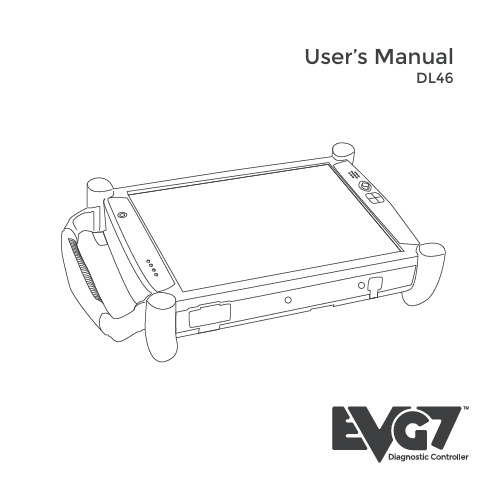
Connect the AC adapter power cord to AC adapter. Connect the AC adapter to the DC power port on th bottom side of your Tablet PC Connect the AC adapter power cord to an AC outlet. Press the power button to turn on the power.
Do not step on or place anyu use the Tablet PC with an extension cord, ensure that the total ampere ratings of all the devices sharing the extension do not exceed the rating of the extension cord or the rating of the wall outlet. Never push foreign objects into the Tablet PC through any of the slots or openings. Dangerous voltages are present, which could cause electric shock or fire, or damage sensitive components.
Turning off the Tablet PC properly is important to maintaining your Tablet PC. 1.On the Start menu, click 2. Click the Turn Off radio button in Turn Off Computer Windows screen, and then click OK If you are going to be away from the Tablet PC for a short period, there are ways of conserving power without shutting down the system. Warning: Shutting off the Tablet PC improperly may result in data loss. Hardware and Software This chapter introduces the different components and controls of your Tablet PC, including the hardware components, the software, and the audio and video systems. Getting Started Before you begin using your Tablet PC, read this chapter to familiarize yourself with the main components installed in the system.
- 1、下载文档前请自行甄别文档内容的完整性,平台不提供额外的编辑、内容补充、找答案等附加服务。
- 2、"仅部分预览"的文档,不可在线预览部分如存在完整性等问题,可反馈申请退款(可完整预览的文档不适用该条件!)。
- 3、如文档侵犯您的权益,请联系客服反馈,我们会尽快为您处理(人工客服工作时间:9:00-18:30)。
第二章 安装..................................................................................................................................... 10 2.1 概述.................................................................................................................................... 10 2.2 开箱................................................................................................................................... 10 2.3 安装与电缆连接................................................................................................................10 2.4 电源说明............................................................................................................................ 13 2.5 指示灯说明........................................................................................................................13
文档修订记录
日期 2016.7.25
版本 V1.0.0
说明 初建
F2X46-D 系列使用说明书
作者 WSP
著作权声明
本文档所载的所有材料或内容受版权法的保护,所有版权由厦门四信通信科技有限公司 拥有,但注明引用其他方的内容除外。未经四信公司书面许可,任何人不得将本文档上的任 何内容以任何方式进行复制、经销、翻印、连接、传送等任何商业目的的使用,但对于非商 业目的的、个人使用的下载或打印(条件是不得修改,且须保留该材料中的版权说明或其他 所有权的说明)除外。
F2X46-D 使用说明书
产品版本 V1.0.0
产品名称:F2X46-D
密级 共 30 页
F2X46-D 使用说明书
此说明书适用于下列型号产品:
型号
产品类别
F2446-D
WCDMA 电力级嵌入式 IP MODEM
F2646-D
EVDO 电力级嵌入式 IP MODEM
F2746-D
TDD-LTE 电力级嵌入式 IP MODEM
商标声明
Four-Faith、四信、
、
、 均系厦门四信通信科技有限公司注册
商标,未经事先书面许可,任何人不得以任何方式使用四信名称及四信的商标、标记。
厦门四信通信科技有限公司
Add:中国厦门市软件园二期观日路 44 号 3 层
http://
客服热线:400-8838-199
第三章 参数设置............................................................................................................................. 15 3.1 界面说明............................................................................................................................ 15 3.2 配置选项说明...................................................................................................................16 3.2.1 “本地串口设置”项:.......................................................................................16 3.2.2 “本地串口 2 设置”项:..................................................................................16 3.2.3 “DTU 工作模式设置”项:.............................................................................. 17 3.2.4 “GPRS 拨号参数设置”项及“GPRS2 拨号参数设置”:................................ 17 3.2.5 “支撑平台相关设置”项:.............................................................................. 17 3.2.6 “企业网关相关设置”项:.............................................................................. 18 3.2.7 “多 IP 数据中心”项:....................................................................................18 3.2.8 “多连接策略”项:...........................................................................................18 3.2.9 “其他配置”项:...............................................................................................18 3.2.10 “网管平台相关设置”项:............................................................................ 18 3.2.11 “管理员登录设置”项:................................................................................ 19 3.2.12 “ICMP 参数设置”项:...................................................................................19 3.2.13 “自定义 UDP 帧格式”项:........................................................................... 19 3.3 读写配置...........................................................................................................................19 3.4 修改配置...........................................................................................................................21
