Cu wire introduction技术资料
氧化铜利兹线

氧化铜利兹线1. 引言氧化铜利兹线(Copper Oxide Litz Wire)是一种用于电磁线圈的特殊导线材料。
它由多股细铜线绕成,每股细铜线表面都覆盖有氧化铜层。
氧化铜利兹线具有低电阻、高频率特性和优异的耐热性能,被广泛应用于电子设备、通信设备、变压器等领域。
2. 氧化铜利兹线的制造工艺2.1 细铜线的选择制造氧化铜利兹线的第一步是选择合适的细铜线。
细铜线应具有良好的导电性能和柔软性,以便于绕成多股线。
2.2 细铜线的氧化处理在细铜线表面进行氧化处理是制造氧化铜利兹线的关键步骤。
氧化处理可以提高细铜线的电阻率,从而减小电流在导线中的损耗。
2.3 细铜线的编织经过氧化处理的细铜线需要编织成多股线。
编织的方式可以根据需要选择不同的结构,常见的编织结构有圆形编织、方形编织和扁平编织等。
2.4 氧化铜利兹线的绝缘处理为了保护氧化铜利兹线免受外界环境的干扰,需要对其进行绝缘处理。
常见的绝缘材料有聚氨酯、聚酰亚胺等。
3. 氧化铜利兹线的特性与应用3.1 低电阻特性由于氧化铜利兹线表面覆盖有氧化铜层,其电阻率较普通铜线更高,因此可以减小电流在导线中的损耗,提高电能的传输效率。
3.2 高频率特性氧化铜利兹线由于细铜线编织而成,每股细铜线之间都有绝缘材料隔离,使得利兹线具有较好的高频率特性。
在高频率电路中使用氧化铜利兹线可以减小信号的衰减和失真。
3.3 耐热性能氧化铜利兹线由于细铜线表面覆盖有氧化铜层,可以提高其耐热性能。
在高温环境下,氧化铜利兹线仍能保持较好的导电性能和绝缘性能。
3.4 应用领域氧化铜利兹线广泛应用于电子设备、通信设备、变压器等领域。
在电感器、变压器中使用氧化铜利兹线可以提高传输效率和稳定性。
在通信设备中使用氧化铜利兹线可以减小信号的衰减和干扰。
4. 氧化铜利兹线的优缺点4.1 优点•低电阻,减小电流损耗•高频率特性,减小信号衰减和失真•耐热性好,适用于高温环境4.2 缺点•制造工艺较为复杂,成本相对较高•对细铜线的要求较高,选择不当可能影响导线的性能5. 结论氧化铜利兹线作为一种特殊的导线材料,具有低电阻、高频率特性和优异的耐热性能。
铜编织线

铜编织线BRAIDED COPPER WIRETZ, TZX铜编织线技术性能(JB2572-79)SPECIFICATION OF BRAIDED COPPER WIRE TYPE TZ,TZX(JB2572-79)铜编织线用于电气装置,开关电器,电炉及蓄电池等的软连接线。
The braided copper wire is suitable for the flexible conductor of electric installation, switch gear, electric frunace, storage battery, etc.1.铜编织线采用优质圆铜线(0.10, 0.15, 0.20)或镀锡软圆铜线(0.10, 0.15)以多股(24.36.48锭)经单层或多层编织成。
2.铜编织线的直流电阻率(20℃)不大于0.022Ω.mm2/m, 锡铜编织镀线的直流电阻率(20℃)不大于0.0234Ω.mm2/m。
3.型号、规格如表1,表2,表3。
1.The braided copper wire is made by braiding a number of spindles(24,36,48) of best quality roundwires(0.10, 0.15, 0.20) or soft tinned wires(0.10, 0.15) to become single layer or multilayer type.2.DC resistivity of copper braided wire (20℃) is not more than 0.022Ω.mm2/m, and the tinned one is notmore than 0.0234Ω.mm2/m.3.Type and specifications are shown respectively in table 1-3.TZ-1 表1 Table 1标称截面NominalCross section(mm2)结构组成股数*根数*套数/单线直径Construction No.ofstrands*No.of wire*layers/single wirediameter(mm)宽度不大于Width≤(mm)厚度不大于Thickness≤(mm)计算重量Calculatedweight (kg/km )16 25 35 50 70 95 24*22*1/0.2024*33*1/0.2024*44*1/0.2024*33*2/0.2024*44*2/0.2024*40*3/0.201618202224203.03.54.05.06.5--166249331498664905。
Inductor Introduction

Chip Coil’s Basic Knowledge 贴片线圈的基础知识1.Chip Coil’s Basic Knowledge贴片线圈的基础知识2.Chip Coil’s Category and Characteristic贴片线圈的种类和特性3. Chip Coil for General Use一般的贴片线圈4.Chip Coil for Choke贴片扼流线圈5.Chip Coil for DC-DC ConverterDC-DC转换的贴片线圈6.Chip Coil for High Frequency高频使用的贴片线圈1.Chip Coil’s Basic Knowledge贴片线圈的基本知识(1)What is Coil?什么是线圈(2)Basic Structure of Coil线圈的基本构造(3)How to Use Coil?线圈的使用方式(4)Part Numbering of Coil线圈的品名编制(5)P/N Example for Chip Coil贴片线圈的品名实例(6)Chip Coil:P/N’s Reading Method贴片线圈的品名方式What is Coil ?何谓线圈Resistor(レジスタレジスタ))电阻Capacitor (キャパシタキャパシタ))电容Coil (Inductor)线圈LRCCoil (Inductor) is one of passive component, which is the same as Resistor and Capacitor.线圈线圈((电感电感))和电阻和电阻、、电容一样是别动器件之一Basic Structure of Coil 线圈的基本构造ConductorFor DC and AC, the value of resistance is greatly different according to the formula below.线圈的阻抗对于直流和交流有很大的不同The DC current can pass through completely (if f =0 ,then Z L =0)Whether the AC current can pass through is determined by its frequency.直流的电流完全能通过直流的电流完全能通过((由于f=0 Z L =0)交流电则要根据频率来决定是否通过Z L =2πf LTherefore ,it is used to separate DC from AC.根据这个原理根据这个原理,,线圈用于交直流的区分How to use coil?①线圈的使用方法线圈使用方法-------It’s used in power line to get solid power supply.Related circuit: Amplifier, IC power line. 使用在电源线上稳定电源相关电路:放大器,IC 电源线Example for Choke circuitpassing an electric current.The current flow is able to continue when the current decreases. (Lenz's law)在线圈不通电流的状况下会持续放电通过线圈的电流减少线圈对外放电线圈使用方法In the circuit of the high frequency, if the characteristic impedance of the circuit (Easiness to pass as shown in signals of the pattern and parts) is not constant, the signal will not be well transmitted. Therefore, when the circuit with a differentcharacteristic impedance ties, it puts among the characteristic impedance adjustment circuits that combine the coil, the capacitor, and resistance, etc. and adjusts it.高频电路当中由于阻抗特性匹配不好造成信号传输不良。
铜缆基础知识

网络综合布线之铜缆基础知识1.1双绞线分类双绞线(TP Twisted Pair)是由两根具有绝缘保护层的铜导线组成。
把两根绝缘的铜导线按一定密度互相绞合在一起,可降低信号干扰的程度,每一根导线在传输中辐射出来的电波会被另一根线上发出的电波抵消。
1.1.1结构分类1.1.2类别分类1.1.3名词解释TIA(Telecommunications Industry Association) 美国电信工业协会EIA(Electronic Industries Association)美国电子工业协会ISO(International Organization for Standardization) 国际标准化组织IEC(International Electrotechnical Commission)国际电工委员会1.2双绞线相关概念1.2.1带宽频率:1.是衡量单位时间内线路中电信号的震荡次数。
2.信道可以不失真地传输信号的频率范围3.单位:MHz1.2.2传输速率:1.是衡量单位时间内线路传输的二进制位的数量2.数据传输速率由单位时间内线路中电信号的震荡次数与电信号每次震荡所携带二进制位(bit)的数量来决定的。
3.单位是MB/s或者Mbps例如带宽就相当于马路,传输速率相当于汽车。
带宽的增加意味着通行能力的增加,而不是提高汽车的速度。
而影响汽车的速度因素有很多如:操作系统、网络上的通信传输协议、传输方式。
一般可以认为高带宽意味着高速率,因为道路宽敞,网络不再拥挤。
但高速率并不一定是高带宽。
如1000Mbit/s的千兆以太网采用4对线全双工的工作方式,对其传输带宽只要求100MHz1.2.3安规(American Wire Gauge)美国线缆规定常用的线规有:1.3护套材料(低烟无卤需要定做的,常规的是700阻燃的)1.3.1 LSZH/LSOH(Low Smoke Zero Halogen)低烟无卤常常指线缆外护套,一般采用FEP(聚全氟乙烯丙)材料;1.3.2可燃性UL94等级是应用最广泛的塑料材料可燃性能标准。
Sn0.7Cu无铅锡条产品介绍 中英文版

产品介绍Product Introduction一、适用范围Scope1.1该承认书只适用于本公司的指定产品:无铅产品。
但因应客户要求,该资料可以免费分发交付客户使用。
The acceptance is just only applicable to the designated lead-free products of the company.But according toclients requirements,the files can be distributed to them for free.The file is suitable for any wire diameter ofthe same alloy composition and flux percentage.1.2本产品应用于环保要求严格的人工焊接和自动焊接。
由高纯度原材料精制而成,在环保型电子装配工业中有广泛应用。
产品执行标准:GB/T20422-2018。
This product is applied for strict environmental requirements of manual welding and automatic welding.Refined with high purity of raw materials,and used widely in environmental electronic assembly industry.Product Executive Standard:GB/T20422-2018.二、产品信息Product information2.1产品名称:无铅锡条Product Name:Lead-free Solder Bar2.2产品型号:107HProduct Model:107H2.3合金规格:Sn-0.7CuAlloy Specification:Sn-0.7Cu2.4产品形状:固体条状Product Shape:solid strip2.5产品特点Product Characteristics2.5.1金属杂质、氧化物含量低。
铜编织线标准
铜编织线标准铜编织线是一种常见的导电材料,被广泛应用于电子设备、通讯设备、汽车电子、航空航天等领域。
为了保证铜编织线的质量和性能,制定了一系列的标准来规范其生产和应用。
本文将对铜编织线标准进行详细介绍,以便相关行业人士了解和遵守相关规定。
首先,铜编织线的标准主要包括以下几个方面,材料、结构、性能、检测方法和标志。
在材料方面,铜编织线应选用优质的电解铜作为原料,并严格控制其化学成分和物理性能。
结构方面,铜编织线应具有一定的编织密度和弹性,以保证其导电性能和耐久性。
在性能方面,铜编织线应具有良好的导电性能、耐腐蚀性能和耐磨损性能。
检测方法方面,应采用相应的试验方法对铜编织线进行质量检验,确保其符合标准要求。
标志方面,应在铜编织线的包装上标明产品的型号、规格、生产厂家等信息,方便用户使用和管理。
其次,铜编织线标准的制定对于保证产品质量、促进行业发展具有重要意义。
通过制定统一的标准,可以规范铜编织线的生产和应用,提高产品的质量稳定性和可靠性,降低生产成本,增强产品的竞争力。
同时,标准化还可以促进行业间的合作与交流,推动技术创新和产业升级,促进行业的健康发展。
最后,铜编织线标准的执行需要全行业的共同努力。
生产企业应严格按照标准要求进行生产,确保产品质量符合标准;用户单位应选择符合标准要求的产品,并加强对产品的管理和维护;行业协会和监管部门应加强对铜编织线产品的监督和管理,及时发现和处理不合格产品。
只有全行业共同遵守标准,才能实现铜编织线产品的优质、高效和可靠应用。
综上所述,铜编织线标准是保证产品质量、促进行业发展的重要依据,全行业应共同遵守和执行相关标准,推动铜编织线产业的健康发展。
希望本文对相关行业人士有所帮助,谢谢阅读。
BallBondingwithPd-CoatedCuWire

Ball Bonding with Pd-Coated Cu WireHorst Clauberg*, John Foley and Bob ChylakKulicke & Soffa Industries, Inc, 1005 Virginia Drive, Fort Washington, PA 19034, USA*E-mail:*****************IntroductionPalladium-coated copper wire has emerged as another low-cost wire option in addition to bare copper wire. Most of the major bonding wire suppliers now offer Pd-coated Cu wire (Pd-Cu wire) in their portfolio and multiple device manufacturers are already using it in fine-pitch applications. Relative to Cu wire, it offers the advantages of a) a substantially more robust 2nd bond process with associated greater ease of dialing in a bonding process and higher mean-time-between-assist rates and b) alternative to use nitrogen instead of forming gas during free-air ball formation. This latter advantage is the main topic of this paper. The disadvantages are a) two to three times greater material cost and b) greater ball hardness and propensity toward pad damage.Balancing these pros and cons, subcons, with their great product mix, often favor Pd-Cu wire for its ease of implementation while still gaining substantial cost savings relative to gold wire. In contrast, IDM’s chose bare Cu wire in the vast majority of applications, since their smaller product portfolio allows them to more thoroughly optimize each individual process.ExperimentalCommercially available 20 μm diameter Pd-Cu wire was bonded on a Kulicke & Soffa Industries IConn automatic wire bonder with a copper kit. Either nitrogen or forming gas (5/95 H2/N2) were used to protect the ball during its formation. 20μm bare Cu wire bonded using forming gas was used for comparison.Second BondSecond bond formation has been one of the challenges to the introduction of copper wire bonding. Key advances for more robust 2nd bond formation with bare copper wire have been the introduction of bonding tools with a rough surface finish, ultra-soft copper wire and the use of scrubbing motions of the bonding tool. With these improvements, robust 2nd bonds are generally achieved. However the bonding tool scrub motions are slow and are one of the main reasons for a reduction in throughput for a copper process relative to the corresponding gold process.Pd-coated copper wire presents yet another option for 2nd bond improvement. Mainly because this wire is free of surface oxides, second bond performance is significantly better than that of bare copper wire in most applications. The advantages are substantially greater ease of process optimization, more robust manufacturing and possibly higher units-per-hour rates through elimination of tool scrub cycles.Fig. 1 demonstrates typcial results, in this case on silver-plated lead frame. The same set of eight bonding parameters were used for both Cu and Pd-Cu wire. Bare copper achieved acceptable results, with Cpk’s ranging from just under 1.5 to about 2.3 using a lower spec limit of 2.5 grams for the stitch pull strength. However, Pd-coated Cu achieved average stitch pull strengths that were more than 50% higher and Cpk’s in the range of 2.5 to 3.Fig. 1: Typical 2nd bond pull strengths (left) and Cpk’s (right) for bare Cu wire and Pd-Cu wires on silver-plated lead frame. Each point is the average value for a DOE cell.Free-air ball (FAB) formationWith a well-designed cover gas system for the electric flame off (EFO) system, the free-air balls at the end of Pd-Cu wire can be formed in nitrogen rather than the forming gas (5/95 H2/N2) that must be used for bare Cu wire. This benefit is likely due to a combination of the absence of oxides on the surface of Pd-Cu that might otherwise interfere with ball formation and a reduced susceptibility to oxidation due to Pd-Cu alloys on the ball surface as it is being formed. Use of nitrogen instead of forming gas is a cost savings, especially since the infrastructure for nitrogen is simpler and often already present on the factory floor.Free-air balls are round and repeatable in both forming gas and nitrogen. Fig. 2 shows typical FAB’s formed in nitrogen. As seen in Fig 3., the standard deviation of ball sizes is well below 1% ofIMAPS/SEMI Workshop on Wire Bondingthe ball diameter over a large range of EFO currents and target ball sizes.Fig. 2: FAB in nitrogen using an EFO current of 90mA.The fate of the Pd during the FAB formation and its influence on first bond performance is the subject of active research [1]. Early papers claimed a uniform, Pd-rich coating of the ball [2]. Although this is occasionally seen for individual balls, Pd distributions are more typically found to benon-uniform. Fig. 4 shows that the pattern of Pd-distribution on and in the ball is a strong function of the EFO current. The grey areas in these images are Pd-Cu alloys that still contain mainly Cu with a low percentage of Pd. The red areas are free of Pd.Fig. 3: Free air ball repeatability for Pd-Cu wire in nitrogen and forming gas for a range of EFO currents. BSR = ball size ratio (Ball diameter/wire diameter). Fig 4: Pd distribution in FAB’s (a) 30 mA, (b) 60 mA and (c) 90 mA. Grey areas are Pd-Cu alloys.Ball BondingBall bond performance of Pd-Cu wire is very similar bare Cu wire with respect to ball dimensions and shear strength. Fig. 5 shows the results of a ultrasonic energy sensitivity study in which the ultrasonic bonding energy was varied over a large range. 20μm Pd-coated copper with nitrogen and forming gas and 20 μm bare Cu in forming gas were bonded with identical bonding parameters targeting a 39 μm bonded ball diameter at the center of the ultrasonic energy (USG) range. The EFO current was set to 60 mA. Only the EFO fire time was adjusted so that the FAB size was the same for all three wire and cover gas combinations.At each USG level, the shear per area was almost the same for the Pd-Cu wire in either cover gas and also the same as for the bare Cu wire (in FG). The top-of-loop pull test showed a few, minor differences (Fig. 6). At low shear/area, Pd-Cu wire had more lifted balls when bonded with nitrogen compared to forming gas. Bare Cu performed better than Pd-Cu wire with respect to ball lifts, but this is at least partly due to approximately 10% lower break strengths for the bare Cu wire. These differences are small enough to be irrelevant in most applications.(b) IMAPS/SEMI Workshop on Wire BondingFig. 5: Shear/area as a function of ultrasonic (US) energy for Pd-Cu wire in nitrogen and forming gas and Cu wire in forming gas.Fig. 6: Correlation of ball lifts during top-of-loop pull tests to shear/area for Pd-Cu wire bonding in nitrogen and forming gas and Cu wire bonded in FG.Pd-Cu wire does have one substantial drawback – a greater propensity for pad peel and damage to fragile dielectrics under the bond pad. This is likely a result of the greater hardness of the FAB caused by formation of Pd-Cu alloys. The data in Table 1 was obtained for a device that was much more sensitive to pad peeling than the device that was used for the experiments illustrated in Figs. 5 and 6. On this sensitive device, pad peeling occured for all of the experiment cells using Pd-Cu wire, whereas 2 of the 3 cells using bare Cu wire did not have any pad peeling. Interestingly, the higher EFO current of 90 mA caused more pad peeling with both Pd-Cu and bare Cu wire. Higher EFO currents are generally believed to be associated with slightly harder FABs. The type of cover gas (N2 or FG) did not appear to have an affect of the pad peeling rate for Pd-Cu wire.Table 1: Aluminum pad peeling rates during top-of-loop pull tests as a function of EFO current on a device with damage-sensitive pads for (a) Pd-coated Cu wire and (b) bare Cu wire. ConclusionsPd-coated Cu wire can be succesfully wire bonded using either forming gas or nitrogen as the cover gas for ball formation. The well-known advantage of Pd-Cu over Cu in 2nd bond is confirmed for silver-plated lead frame. These advantages come at the expense of a greater propensity toward pad damage and about 2 to 3 times the material cost.AcknowledgmentsAlan Slopey, Joe Fiorillo and Drew Pursell are thanked for the wire bonding, Son Nguyen for his patience in cross-sectioning and Virginia Mota for metrology. Jon Brunner and Gary Gillotti are thanked for their fruitful advice.References1. J. Yeung, D. Spephan, F. Wulf, “Comparison ofBare Copper and Palladium Coated Copper Wirein Wire Bonding, this IMAPS workshop (2010). 2. T. Uno, S. Terashima and T. Yamada“Surface-Enhanced Copper Bonding Wire for LSI”, 2009 Electronic Components and Technology Conference, p.1486 (2009).3. B. Zhang, K. Qian, Y. Cong, M. Zhao, X-Q. Fanand J-J. Wang, “Behaviors of Palladium in Palladium Coated Copper Wire Bonding Process”, 2009 International Conference on Electronic Packaging Technology & HighDensity Packaging (ICEPT-HDP), p. 662 (2009).。
铜冶炼技术教材【专业英语】
1. Overview
1.1. Introduction 1.2. Extracting Copper from Cu-Fe-S ores
- Conபைடு நூலகம்entration flotation - Matte smelting - Converting - Direct-to-copper smelting - Fire refining and electrorefining of blister copper 1.3. Hydrometallurgical Extraction of Copper -Solvent extraction - Electrowinning 1.4. Melting and casting cathode copper - Types of Copper Product 1.5. Recycle of copper and copper-alloy scrap
9. Bath matte smelting: Ausmelt/Isamelt and Mitsubishi
9.1. Basic operations 9.2. Feed materials 9.3. The TSL furnace and lances 9.4. Smelting mechanisms - Impurity elimination 9.5. Startup and shutdown 9.6. Current installations 9.7. Copper converting using TSL technology 9.8. The mitsubishi process - Introduction the mitsubishi process - Smelting furnace details - Electric slag-cleaning furnace details - Converting furnace details - Optimum matte grade - Process control in mitsubishi smelting/converting 9.9. The Mitsubishi Process in the 2000s
铜线工艺介绍-2012 Nov
未氧化的Cu线焊球 Un-oxidized Cu Ball
已氧化的Cu线焊球 Oxidized Cu Ball
ü 铜线的硬度比金线大,需要更高的键合功率,如果氧化了会更硬,易产生Pad Al的挤出问题;易造成Pad 金属下的Si衬底破损,出现弹坑。 High bonding power needed due to copper hardness. Harder if oxidized, easy to cause the Pad Al extrusion; easily lead to the Si substrate Pad metal damage and appeared crater.
Subcon Cu Wire Transition Trend
7ing
50%
40%
30%
20%
10%
0% Y2009
Y2010
Y2011
Y2012
• BCD has shipped more than 1500KK Cu parts in the past years.
BCD Cu Wire Shipment Trend
2500 2000 1500 1000
500 0
Y2009
Y2010
Y2011
Y2012
Shipment(kk)
7
铜线产品业务趋势 Copper wire business development trend n Yield : Equivalent between Cu and Au
CopperWirebonding
> 2 mil 2 mil 1.5 mil 1.3 mil 1 mil > 1mil
(estimate based on K&S wire = 50% market share for Cu Wire)
Confidential
March 2006
0.8 $107 $135 $184 $33
Cu Cu
Cu
Cu
J. P. Morgan “ the price of gold may exceed US$800 an ounce if Iran’s nuclear issue heats up ... otherwise it is $600 by the end of the year”
Wire Diameter
Fine Wire Kit 0.8 – 1.3 mils
Heavy Wire Kit 1.3 – 2.75 mils
EFO and Glass tube Flow meter assembly 20 mil EFO wand
EFO and Glass Tube Flow meter asmbly 32 mil EFO wand Hi V/ I EFO box/Cable Heavy Wire Clamps
Confidential
March 2006
Asymmetrical Bonds vs. EFO Current Settings
Recommended For Heavy Wire (> 1.5 mil) & Large Ball
Target size / ht. Club bond Club bond
铜互连技术

铜互连技术周江涛、周长聘、严玮俊、沈系蒙、陈龙摘要:在集成电路中采用双镶嵌工艺制备互连线,铜作为互连线的材料具有低电阻率和较好的抗电迁移能力等优点,同时存在新的缺陷模式如沟槽缺陷、气泡缺陷、金属缺失等,目前的工作主要是该工艺的完善。
1、引言:铜互连技术指在半导体集成电路互连层的制作中采用铜金属材料取代传统铝金属互连材料的新型半导体制造工艺技术。
由于采用铜互连线可以降低互连层的厚度,使得互连层间的分布电容降低,从而使频率提高成为可能。
另外,在器件密度进一步增加的情况下还会出现由电子迁移引发的可靠性问题,而铜在这方面比铝也有很强的优越性。
铜的电阻率为1.7μΩ•cm,而铝的电阻率为2.8μΩ•cm,所以铜的导电率大大高于铝。
由于采用铜互连线可以降低互连层的厚度,使得互连层间的分布电容降低,从而使频率提高成为可能。
另外,在器件密度进一步增加的情况下还会出现由电子迁移引发的可靠性问题,而铜在这方面比铝也有很强的优越性,铜的熔点为1083℃,铝的熔点为660℃,铜更不容易发生电迁移。
铜互连技术于1998年被引入后,得到了良好的发展,目前已经成为130nm以下节点技术所必须采用的工艺技术。
当前铜互连层已经由原来的6~7层发展到现今的9~10层。
本文将按如下次序介绍:Cu淀积(用于生长籽晶);铜图形化方法--铜图形化有三种方法:镶嵌工艺(damascene), 剥离工艺 , 铜刻蚀;抛光(完成互连制备)。
铜互连工艺简介:Cu的互连工艺最早在1997年9月由IBM提出来的,被称为是镶嵌工艺(也称大马士革)。
并应用于制备微处理器、高性能存储器及数字信号处理器等等。
它采用对介电材料的腐蚀来代替对金属的腐蚀来确定连线的线宽和间距。
镶嵌工艺分为单镶嵌和双镶嵌。
它们的区别就是在于穿通孔和本曾的工艺连线是否是同时制备的。
2、铜籽晶层制备经过一系列布线刻槽和穿通孔加工完毕后,是Cu的淀积过程。
由于铜虽然电阻率和电迁移特性优于铝, 但是也有不如铝的方面。
CommScope 铜系列分布系统解决方案数据表说明书
DATA SHEET Racks and PanelsCopper portfolioCommScope offers variants of “copper” based distributionsystem solutions for all parts and applications of the subscriberaccess and transmission network. The range of the productsdiscussed in this document enables the customer to set upmodular distributors in every size required. The differentsystem solutions are flexible, easy to install and offer a cleararrangement of the connectivity components, as well as easeof copper cable jumpering.The frames present the interface between copper cablesarriving from the local network subscriber side and differenttypes of active equipment. The portfolio enables customers toselect all configuration sizes variants from small rack type up tomedium and large-scale distribution MDF. They will cover tosolve the most varied requirements and to fit into the mostvaried spaces. Their connection components are based on theproven KRONE style products LSA-PLUS® series 2 or LSA-PLUS® HD180 using the LSA-PLUS® quick connectiontechnology inside.1.Distribution frame 800Up to 1400 pairs per rack unittermination of up to 800 pairs (LSA-PLUS Series 2) and 1400 pairs(LSA-PLUS HD180). Accessories like Jumper Rings arepermanently fixed to the distribution frame and allow thejumper wires to be run between columns horizontally and alsovertically. There are two different base sizes to cater for sitesthat have limited space.Earthing is carried out by either an earth bar across the base ofthe frame or individual earth wires.Features & benefits•Flexible in use, i.e. free-standing version, back-to-backmounting or wall mounting•Easily extendable•High density•Room for easy termination, wiring and jumpermanagement•Accommodates LSA-PLUS S2 and HD180 for PROFILE rodinstallations only•Easy to assemblyDesign and configurationsGeneral attributes & mechanical characteristics•Product specifications:o Dimensions:H2200 x D309 x W251 (mm) o Material (frame): Galvanized steel with epoxy o Material (round bars): Stainless steel (diameter 12 mm) o Color:grayo Contact resistance: <10mΩ (between racks, in frame)o Usable profile bar length:▪ Upper section: 853 mm ▪ Lower section: 1022mmProduct offering - Distribution frame 800Distribution 108A & City 80 framesUp to 1600 pairsThe distribution 108A& City 80 frames are vertical, modular distribution frames offering up to 1600 pairs capacity. Themodular construction allows units to be assembled side-by-side for wall mounting, or back-to-back for free-standing applications.Earthing is provided via a heavy copper earth communing bar fitted to the bottom of the frame and running the full width of the frame. Adjustable legs allow for uneven flooring or may be removed where height is a limitation.Features & benefits• Cable management•Two distribution racks can be fixed together with bolts (not included in delivery) to form banks•Flexible in use, i.e. free-standing version, back-to-back mounting or wall mounting•A sufficient number of cable guides are pre-installedDesign and configurationsGeneral attributes & mechanical characteristics•Installation:o The distribution rack is delivered completely assembled without wall- and side fixing material.•Product specifications:o Material: Sheet steelo Color:Black (RAL 9011)Figure 1: Distribution frame 108A – one vertical (64201050-00)Figure 2: Distribution frame 108A – two verticals (64201013-00)Figure 3: City 80 frame – twoextended verticals (64201013-12)Product offering - Distribution 108A & City 80 framesProduct offering - Distribution 108A & City 80 framesLSA-PLUS® SubracksFor 19-inch rackThis section provides an overview of the different 19-inch racks suitable for LSA PROFIL system. The racks can be used for setting up small, compact distribution units.Figure 4: 19” Subrack for 4HU/7SU LSA-PLUS® Series 2 or HD180 PROFIL, with Jumper rings [MID: 66901371-00]Features & benefits• Designed for installation in 19-inch racks • Suitable for PROFIL modules and Back • Included cable supported • Included perforated rail •FlexibilityConfiguration capabilities• Installation: The racks are delivered unmounted. •Product specifications:o Material (subrack): Sheet steel o Material (Profil rods):Stainless steelDesign and configurationsFigure 7: 19” Subrack for 3U LSA -PLUS® Series 2 or HD180 PROFIL [MID: 66901300-00]Figure 8: 19” Subrack for 3U LSA-PLUS® Series 2 or HD180 PROFIL – C1 module rack [MID: 66901125-00]Figure 6: 19” Subrack for 3U LSA -PLUS® Series 2 Back Mount Frame, recessed [MID: 64502006-00]Figure 5: 19” Subrack for 3HU LSA-PLUS® Series 2 Back Mount Frame, Flush mount [MID: 64501008-00]Product offering - 19-inch LSA-PLUS® SubracksOrder Number DescriptionBACK MOUT FRAME TYPE64501202-00 19” Subrack for 1HU BMF – 3 modules, flush mount64501008-00 19” Subrack for 3HU BMF – 15 modules, flush mount64502009-00 19” Subrack for 2HU BMF – 9 modules, recessed64502006-00 19” Subrack for 3HU BMF – 15 modules, recessedPROFIL ROD TYPE66901300-00 19” Subrack for 3HU PROFIL – DATA rack66901125-00 19” Subrack for 3HU PROFIL – C1 module rack (only rods)66901371-00 19” Subrack for 4HU/7SU PROFIL – with jumper elements, bracket for cable fixationVisit our website or contact your local c for more information.© 2021 CommScope, I nc. All righ ts reserve d.Unless otherwise noted, all trademarks ide ntifie d by ® or ™ are registere d trade marks, respectively, of CommScope, Inc. This document is for planning purposes only and is not in tende d to modify or suppleme nt any specifications or warranties relating to CommScope products or se rvices. CommScope is committe d to the highest standards of bus iness inte grity and environmentalsustainability with a number of CommScope’s facilities across the globe certified in accordan ce with international s tan dards, including ISO 9001, TL 9000, and ISO 14001.Further information regard ing CommScope’s commitment can be found at /Abou t-Us/Corporate-Responsibility-and-Sustainability.。
铜缆
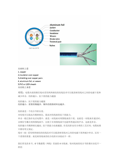
从材料上看
1, copper
2,insulation over copper
3,shielding over copper pairs
4, aluminum foil, or weave
5,PVC or LSZH sheath
从结构上来看
对绞:电缆内部的铜芯线对采用两两相绞的绞线技术可以抵消相邻线对之间的电磁干扰和减少串音,绞距越小,抗干扰的能力越强
绞距越小,抗干扰的能力越强
绞距越小,需要的铜越多,铜外的绝缘材料也越多。
绞距就是一个绞合节距长度。
对绞线可以提高共模抑制比,提高对绞线束的抗干扰能力。
串音一般泛指在电话电缆中,就是一对线束对周围线束的干扰,也就是一对线束在通话时,音频信号耦合到周围线束中,以致于在周围线束中也能听得通话的声音,这就是串音。
绞距越小共模抑制比越高,抗干扰能力也就越强。
但是绞距也有合理的工艺区间,电缆标准中都有明文规定。
线对(束)采用两两相绞的绞线技术可以抵消相邻线对之间的电磁干扰和减少串音,还有一个重要的要素,就是相邻线束的绞合绞距应该彼此不一样。
我们常见的5号、6号数据缆(网线)里面的4对线束,每对线束的绞合节距都应该是不一样的。
《接入网技术 》 第2章 铜线接入技术

ADSL基本原理及特点
传统的电话线系统使用的是铜线的低频部分(4kHz以 下频段)。而ADSL采用DMT(离散多音频)技术,将原 来电话线路4kHz到1.1MHz频段划分成256个频宽为 4.3125kHz的子频带。
其中,4kHz以下频段仍用于传送POTS(传统电话业务 ),20KHz到138KHz的频段用来传送上行信号, 138KHz到1.1MHZ的频段用来传送下行信号。DMT技术 可以根据线路的情况调整在每个信道上所调制的比特数, 以便充分地利用线路。
铜线接入线路分类
(2)音频对称电缆
音频对称电缆是由多股绝缘芯线按照一定的规则扭绞而成。 以话音信道为主要传输媒质的通信电缆(模拟用户环路的传输媒 质),话音信道是指传输频带在300~3400Hz的音频信道。 其芯线线径为0.4~0.9mm的铜线,每一芯线的外面用绝缘的纸 或塑料覆盖而成,多股绝缘芯线按照成对扭绞或星型四线组扭绞 的方式,并通过变换扭矩来减少不同线对之间的串音干扰。一条 大容量的音频对称电缆是由若干“扎组”构成,每个扎组由若干 “线对多元组”组成,一个线对多元组又包含若干个“线对单元 ”,一个线对单元可以包括12、13或50对等双绞线
铜线接入线路分类
铜线接入线路又分为双绞铜线,音频对称电缆和同轴 电缆
(1)双绞线 把两根绝缘的铜导线按照一定的密度逆时针互相绞在一起, 可降低导线彼此产生信号的干扰程度,每一根导线在传输中辐 射的电波会被另一根线上发出的电波抵消。其中绝缘外套中包 裹铜线两两相绞,形成双绞线对,因此得名双绞铜线。 双绞线数据电缆,按频率和信噪比可分为:3类,4类,5 类和超5类等。现在很多地方已经用上了六类线甚至七类线。 用在计算机网络通信方面至少是3类以上。
一般来说,子信道的信噪比越大,在该信道上调制的比 特数越多,如果某个子信道信噪比很差,则弃之不用。 ADSL可达到上行640kbps、下行8Mbps的数据传输率。
Belden 14 AWG 氧化铜导线说明书

1
14 104x34
Total Number of Conductors:
1
Insulation Insulation Material:
Insulation Material
Wall Thickness (mm)
HDPE - High Density Polyethylene 0.8128
Overall Insulation Overall Cable
EU Directive 2011/65/EU (ROHS II):
Yes
EU CE Mark:
No
EU Directive 2000/53/EC (ELV):
Yes
EU Directive 2002/95/EC (RoHS):
Yes
EU RoHS Compliance Date (mm/dd/yyyy):
07/01/2004
EU Directive 2002/96/EC (WEEE):
Yes
EU Directive 2003/11/EC (BFR):
Yes
CA Prop 65 (CJ for Wire & Cable):
Yes
MII Order #39 (China RoHS):
Yes
Plenum/Non-Plenum
Page 2 of 2
11-05-2015
Plenum (Y/N):
No
Electrical Characteristics (Overall)
Nom. Conductor DC Resistance: DCR @ 20°C (Ohm/km) 8.26812
Suggested Working Voltage:
铜导线公制连接器
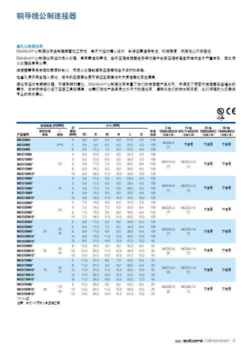
单孔公制接线耳Blackburn ®公制接线耳由电解铜管加工而成,其尺寸经过精心设计,能保证最佳导电性、机械强度、抗振性以及拔插性。
Blackburn ®公制接线耳经过退火处理,具有最佳延展性。
由于压缩连接器在安装过程中会因压缩或弯曲而造成舌片严重变形,因此退火处理非常有必要。
连接器需有承受振动载荷的能力,而退火处理能避免压接筒和舌片间材料断裂。
检查孔便于完全插入导线,适中的压接筒长度可保证压接操作中方便准确地定位模具。
接线耳经过电镀锡处理,可避免铜材氧化。
Blackburn ®公制接线耳丰富了我们的连接器产品系列,并满足了顾客对连接器日益增长的需求。
本手册详细介绍了压接工具和模具,如需订购该产品目录之外尺寸的接线耳,请联系我们的技术服务部,他们将随时为您提供专业的技术建议。
电缆连接器71 RA导线规格 (SQMM)Ø 螺柱尺寸 (MM)标准 6 吨 TBM62BSCR 14 吨 BPLT14BSCRI 26 吨 TBM26MCC 60 吨TBM60MCC 低绞合度| 7095MCD95-6 (2) MCD95-14(1)MCC95M10*9510 13,5 25,0 11,0 10,0 56,5 10,5 25不适用 不适用MCC95M12*12 13,5 25,0 14,0 12,0 61,5 13,2 25*UL ®认证注意:参见100页的公制压接工具。
电缆连接器71 RA导线规格 (SQMM)Ø 螺柱尺寸 (MM)标准 包装 6 吨 TBM62BSCR (压接工具)14 吨 BPLT14BSCRI (压接工具)26 吨 TBM26MCC (压接工具)60 吨TBM60MCC (压接工具)低绞合度导线| 软线1000800不适用不适用不适用MCD1000-60(2)MCC1000M202044,0 80,0 24,0 23,0 162.021,0 2*UL ®认证注意:参见100页的公制压接工具。
微小互连Cu
微小互连Cu0 序言现代电子信息技术的飞速发展,使得电子产品越来越普及. 在电子产品制造中,将晶片、阻容、MEMS等微元件加工组合构成微系统及工作环境的技术称为电子封装. 作为重要的制造技术,电子封装得到了广泛的研究[1-3]. 互连技术是电子封装中的关键步骤,其中钎焊在互连技术中应用最广.经钎焊获得的接头在封装中既起到机械支撑作用又起到电气连接作用. 随着微电子技术的发展进入集成系统芯片和模块芯片时代,微芯片对互连技术提出了高密度互连和高信号传输率的要求,这就需要接头具有较高的强度与服役温度. 然而,传统的电子封装研究[4-6]中接头的相组成以钎料为主,IMC(intermetallic compound)层则要尽可能的薄,因为金属间化合物是脆性物质,会导致接头可靠性下降. 但是,钎料强度不高,而IMC具有很高的强度,因此对稳定的全IMC接头的制备工艺及强度分析的研究是具有重要意义的. 固液互扩散键合法(solidliquid-inter-diffusion bonding)采用低温钎料锡在较低的温度下就可以键合形成全金属间化合物. 而IMC的熔点相比钎料要高很多,因此就可以达到低温键合,高温服役的效果.目前,Cao等人[7]在研究SLID键合方法时发现,若锡层厚度过薄其润湿性不好,会在接头中产生空洞,而过厚的锡层则会在熔化后由于压力而溢出,容易在电路板上发生短路. Liu等人[8]对接头结构做了进一步的优化,采用双钎料层结构,在钎料熔化后形成液液接触而非固液接触,有效提高了润湿性,进而提高接头界面质量、可靠性增强. Mo等人[9]对2.5 μm厚镀锡层焊点进行了低温钎焊研究,得到了Cu3Sn-Cu6Sn5-Cu3Sn与全Cu3Sn两种全IMC接头.在以上研究中,均是通过电镀的方法在铜基板沉积Sn层作为钎料,其优点是厚度可控,且双钎料层可以提高润湿性. 但是镀锡钎料往往会在界面反应过程中产生大量的空洞,从而影响接头的结合强度. 在电镀过程中电镀液浓度、环境温度、电流密度等因素均会对镀锡层的形貌质量造成影响[10-15].文中直接采用厚度为25 μm,表面平整的高纯Sn箔作为钎料,避免了电镀过程中容易出现的Sn层缺陷导致界面缺陷.关于接头的剪切性能,Choudhury等人[16]对接头中IMC体积分数占比与其强度之间的关系进行了研究. 研究结果说明随着IMCs的增加,接头的强度升高. Osborn等人[17]指出全IMCs接头连接强度更大程度的依赖于IMCs本身的性能,但IMCs因其脆性而被普遍认为机械性较差. Lee等人[18]认为是工艺–微观组织–性能内在的联系导致接头强度的不同.绘画审美上,中国画追求诗意的传达。
引线框架铜合金材料与SnAg3.0Cu0.5的界面组织
引线框架铜合金材料与SnAg3.0Cu0.5的界面组织集成电路由芯片、引线框架、塑封三部分组成,其中引线框架的作用是导电、散热、连接外部电路。
制作引线框架的材料不仅要具有高强度、高导电、高导热性能,而且还要有优良的钎焊性能,近年来铜合金引线框架材料因其优良的性能得到了广泛的应用。
引线框架通过引脚采用钎料进行焊接形成焊点,从而实现电子封装中的各级焊接。
当钎料与铜合金母材充分润湿形成焊点后,会在其界面处形成一层金属间化合物。
钎焊初期形成的金属间化合物可以确保铜合金母材与焊料之间有良好的冶金连接,金属间化合物的厚度直接影响焊点的性能,当金属间化合物的厚度小于1μm时,焊料和金属间化合物之间没有裂纹产生;当金属间化合物厚度介于1-10μm之间时,抗拉强度开始下降;当金属间化合物厚度大于10μm时,随着残余应力的积累,金属间化合物与焊料的拉伸强度显著下降,直至断裂。
电子设备出现的故障中有很大一部分是由于焊点接触不良造成的,尤其是移动式设备,焊点可靠性问题受到了越来越多的重视。
随着表面组装技术的迅速发展及无铅钎料的应用,无铅钎料焊点的可靠性已成为近年来微连接领域关注的热点之一。
在众多的无铅钎料合金当中,SnAgCu合金以其优良的润湿性能及力学性能被认为是最有潜力的含铅钎料的替代品。
金属间化合物的晶体结构、形貌以及它们对焊点力学性能的影响已经有人进行了大量的研究,但不同的铜合金成分对无铅焊料与铜合金框架材料的界面金属间化合物的影响却很少有人进行研究。
新型高性能框架材料Cu-Cr-Sn-Zn系合金具有优良的高导电性、高强度、耐软化温度、冲压成形性、电镀性等性能而得以开发。
日本报道的该合金的导电率为80/75%IACS,抗拉强度35/65kgf/mm2,显微硬度105/195HV,目前国内对该合金系的研究甚少。
本文着重研究该合金与目前常用的Cu-Fe-P系、Cu-Cr-Zr系合金与SnAgCu系钎料的钎焊焊点界面组织,比较不同的引线框架铜合金材料与SnAgCu系钎料焊点在焊接后以及经高温恒温时效后的界面组织,探讨了不同的铜合金成分对引线框架铜合金材料与SnAgCu 钎料界面金属间化合物厚度的影响。
引线框架铜合金
引线框架铜合金材料1)介绍引线框架:作为集成电路的芯片载体,是一种借助于键合材料(金丝、铝丝、铜丝)实现芯片内部电路引出端与外引线的电气连接,形成电气回路的关键结构件,它起到了和外部导线连接的桥梁作用,绝大部分的半导体集成块中都需要使用引线框架,是电子信息产业中重要的基础材料。
2)优势所在:科学技术现代化对铜及铜合金材料提出越来越多的新要求,引线框架的作用是导电、散热、联接外部电路,因此要求制作引线框架材料具有高强度、高导电、良好的冲压和蚀刻性能。
目前全世界百分之八十的引线框架使用铜合金高精带材制作,据不完全统计,引线框架合金约77种,按合金系划分主要有铜-铁-磷、铜-镍-硅、铜-铬-锆Cu-Fe-P、Cu-Ni-Si、Cu-Cr-Zr 三大系列,按着性能可分为高导电、高强度、中强中导等系列所有这些新要求,将推动铜及铜合金材料的现代化进程。
常用的铜基引线框架材料主要有C194和KFC合金,其中C194 (Cu-2.3Fe-0.1Zn-0.03P)属于Cu-Fe-P系合金,具有高导电、高导热性以及好的热稳定性,大量应用于电子封装(安装集成电路内置芯片外用的管壳,起着安放固定密封,保护集成电路内置芯片,增强环境适应的能力,并且集成电路芯片上的铆点也就是接点,是焊接到封装管壳的引脚上的)领域。
C194合金(Cu-2.35%Fe-0.12%Zn-0.03% P)是美国奥林公司20世纪60年代开发生产的引线框架材料,因其优良的导电性、导热性和低价格等特点成为引线框架材料的主导产品。
目前日本和德国是世界上最大的引线框架铜带出口国, 我国虽然可以自行生产一定量的C194合金材料,但合金性能与国外产品相比存在一定差距,国外合金性能为:抗拉强度500MPa,硬度151HV,电导率3.77×10⁻²S/m;而国内合金性能为:抗拉强度≥410 MPa,硬度120~145HV,电导率≥3.48×10 -2S/m。
- 1、下载文档前请自行甄别文档内容的完整性,平台不提供额外的编辑、内容补充、找答案等附加服务。
- 2、"仅部分预览"的文档,不可在线预览部分如存在完整性等问题,可反馈申请退款(可完整预览的文档不适用该条件!)。
- 3、如文档侵犯您的权益,请联系客服反馈,我们会尽快为您处理(人工客服工作时间:9:00-18:30)。
RealValueTM2008Introduction for Copper wireWe Pursue Beyond the Perfection TM2008 MK Electron Co., Ltd1. General informationRealValue™MK Electron Co, Ltd. 2008Beyond the Perfection TMDevelopment Background Market Demand¾ To minimize package manufacturing costÆ The lowest material cost Functional Demand¾ To maximize the package’s operating speedÆ Lower electrical resistance (Ag < Cu < Au < Al)¾ To maximize reliability of the packageÆ 100 times slower IMC growth rate (Al pad) Æ Higher strength which lowers mold sweep ratio Æ The best bondability (Cu wire on Cu pad)RealValue™MK Electron Co, Ltd. 2008Beyond the Perfection TMMerits & Demerits Merits• Excellent Electrical Properties Æ Lower Electric Resistivity • Excellent Mechanical Properties Æ Lower Wire Sweep during the Molding • Higher Bond Reliability and Device Performance Æ Hard to Form Harmful Intermetallic Compound Demerits• Oxide Formation in Wire Bonding Process • High Deformation Resistance of Free Air Ball • Chip Cratering & Pad PeelingRealValue™MK Electron Co, Ltd. 2008Beyond the Perfection TMManufacturing Process OverviewComposition Analysis Cu raw material (99.999% up) Doping (ppm Order) Continuous CastingClass 100Outgoing Inspection • Mechanical Properties • Despooling Test • Surface Condition • Labeling Visual InspectionClass 1,000Dia. CheckDrawingCleaningDeliveryPackingWindingMechanical Property CheckAnnealingRealValue™MK Electron Co, Ltd. 2008Beyond the Perfection TMProcess Difference Easy to form Cu oxide at high temperatureÎ Rapid cooling down to room temp. just after casting in inert gas atmosphereCooling ZoneWater Jacket Î Special atmosphere control in annealing process by the dual annealing systemAnnealing ZoneCooling Zone5%H2 + N2 Bal. (Preheated Gas)RealValue™Heating ElementQuartz TubeN2 Gas (Cooled Gas)Beyond the Perfection TMMK Electron Co, Ltd. 2008Forming gas for anti-oxidation9 Necessary of Cu bonding kit 9 Blowing direction and flow rate of forming gasEFO Torch BlowASM Cu Bonding KitForming Gas 5%H2 + N2RealValue™MK Electron Co, Ltd. 2008Beyond the Perfection TMRaw material comparisonPhysical PropertiesAtomic Weight Crystal Structure Density (at 20 oC) Melting Point Heat of Fusion Thermal Expansion Coeff. (0 - 100 oC) Heat Conductivity (0 - 100 oC) Specific Heat (0 - 100 oC) Electrical Resistivity (at 20 oC) Tensile StrengthRealValue™Cu63.54 FCC g/cm3oAu196.97 FCC 19.32 1064.18 12.4x10⁻³ 14.1x10⁻⁶ 315.5 130 2.4x10⁻⁸ 118.94 1084.62 13.1x10⁻³ 17.0x10⁻⁶ 397 386 1.67x10⁻⁸ 20CJ/mol / oC W/m.K J/kg.K Ohm-m Kgf/mm2MK Electron Co, Ltd. 2008Beyond the Perfection TMCu wire ProductCu wire have higher tensile strength than Au wireTensile strength at room temperature16 14 LV CD Gold [1.0mil] Characteristic by Cu wire typeBreaking Load (gr)CD type : Adopted for SO, TO PKG Stable performance CS type : Adopted for fine pad pitch PKG Lower hardness and stable 2nd bond LV type : Newly developing to prevent pad cratering & short tail12 10 8 6 4 2 0 2 < Gold > < Copper >46810121416Elongation (%)RealValue™MK Electron Co, Ltd. 2008Beyond the Perfection TMElectrical Resistance Low electrical resistance allows higher PKG speed30 27 Test ConditionTest Temp. : 25 +/- 1oC Tester : Nano-voltmeter (HP34420A) Wire Length : 300mmResistance (ohm)24 21 18 15 12 9 6 3 0.8 1.0 1.32N Au 4N Au 4N Cu Electrical Resistivity 2N Au = 2.90X10⁻⁸ ohm.m 4N Au = 2.30X10⁻⁸ ohm.m 4N Cu = 1.95X10⁻⁸ ohm.m Wire Size (um)RealValue™MK Electron Co, Ltd. 2008Beyond the Perfection TMWire hardness(Unit : Hv)Cu wire LV FAB 1.0mil WireTest ConditionAu wire CD 60 ~ 70 65 ~ 75/CS 55 ~ 65 65 ~ 75/4N 35 ~ 40 60 ~ 65Creep : 5sec2N 40 ~ 45 65 ~ 7050 ~ 60 60 ~ 70• Load : 50mNLoading time : 10sec※ Check the hardness in the same test conditions between C/W and G/WFISCHERSCOPE HM2000Bare wire & Bonded Ball RealValue™MK Electron Co, Ltd. 2008Beyond the Perfection TMFusing current(Unit : A)Wire length = 5mm Cu wire LV 0.8mil 0.9mil 1.0mil 1.2mil 1.5mil 2.0mil 0.44 0.52 0.62 0.79 1.08 1.63 CS 4N 0.41 0.48 0.56 0.70 1.03 1.53 Au wire 2N 0.40 0.47 0.54 0.68 1.00 1.49 LVWire length = 10mm Cu wire CS 0.40 0.45 0.54 0.66 0.86 1.28 4N 0.39 0.43 0.49 0.61 0.80 1.19 Au wire 2N 0.38 0.42 0.48 0.59 0.78 1.15RealValue™MK Electron Co, Ltd. 2008Beyond the Perfection TMBondability Bonded Ball Size : 2WD Wire Bonder : ASM Eagle 60 Test Die : Al-1.0Cu-0.8Si Pad200< Ball Shear Test >Bond Pull Test (grf)Au wire Cu Wire60 50 40 30 20 10 0< Bond Pull Test >Au wire Cu WireBall Shear Test (grf)150100500 1.0mil 1.3mil 2.0mil1.0mil1.3mil2.0milWire diameterWire diameterRealValue™MK Electron Co, Ltd. 2008Beyond the Perfection TMReliability of Cu wire Cu wire have higher reliability than Au wireTheoretical growth rate of IMC for Cu wire is around 100 times slower than that of Au wire< IMC and Kirkendall void formations > Test ConditionÆ Baking Temp. : 175 C Æ Baking Time : 1,000hroCu wire 1.0milAu wire 1.0mil< Thermal conditions for 100Å thick IMC formation >ItemsTime for IMC formation at 200oC Temp. for IMC formation in 0.15secRealValue™MK Electron Co, Ltd. 2008Cu-Al17sec 320oCAu-Al0.25sec 220oCBeyond the Perfection TM2. Latest Cu wire(Low hardness Cu wire)RealValue™MK Electron Co, Ltd. 2008Beyond the Perfection TMWork-hardening of Cu wire Effect of work-hardening & hardness; Work hardening & hardness of Cu wire cause chip damage and short tail problem Æ Work-hardening : Increment of metal hardness as the degree of transformationFAB hardness65% increaseBonded ball60.00 50.00 Force(mN) 40.00 30.00 20.00 10.00 0.00 0.00Test condition -. Wire Dia. : CD 2.0mil -. Load : 50mN -. Loading time : 12sec -. Creep time : 5secForce change as indenting depth4N 4N 4N 4N Au Cu Cu Au (Bonded ball) (Bonded ball) (FAB) (FAB)118Hv46Hv72Hv 25Hv 50Hv75Hv[ Cratering ]-. BAR : 0.25 (Height / Width)0.501.00 Depth(um)1.502.00[ Short tail ]RealValue™MK Electron Co, Ltd. 2008Beyond the Perfection TMWhat is difference ? Transformation of hardness value[ Unit : Hv ]Wire G/W C/W[CD type]FAB39.5 60.2 54.3Bonded Ball66.3 105.5 89.061.2 63.9 62.0C/W[LV type]Test condition -. Wire Dia. : 1.0mil -. Load : 50mN -. Loading time : 10sec -. Creep time : 5sec< Wire >< FAB >< Bonded Ball >Æ Though wire hardness are almost same, there are big differences in FAB and bonded ball hardness between Copper and gold wire.RealValue™MK Electron Co, Ltd. 2008Beyond the Perfection TMConcept of LV type Low hardness Pad damage Short tail• Apply optimized alloy design to reduce the work-hardening Process Improvement Ball shape Bondability• Uni-directional solidification • Uniformity of grain sizeLV typeBonded Ball HardnessCD type 105.515% reduceLV type 89.0RealValue™MK Electron Co, Ltd. 2008Beyond the Perfection TMBonded Ball Hardness At the same bonding conditions, ball height of LV and CD type are differentLV typeBonded Ball Hardness120 110Hardness [Hv]19.2um100 90 80 70 60105.5 89.0CD typeLVCDTest condition -. N = 20-. LV type is softer than CD type20.1um-. Tester : Micro hardness tester -. Wire Dia. : 1.0mil -. Load : 50mN -. Loading time : 10sec -. Creep time : 5secduring the bondingRealValue™MK Electron Co, Ltd. 2008Beyond the Perfection TMHardness Comparison Bonded ball hardness105100.8100Hardness [Hv]96.5 92.7 93.4 86.995 90 85 80 75 2N G/W Comp-4N78.6Comp-5NCDCSLV9 Measuring condition Æ LV is softer than other typeÆ Test M/C ; FischerscopeÆ Indent Load ; 50mN Æ Loading Time ; 10secRealValue™MK Electron Co, Ltd. 2008Æ N = 5ea Æ Creep ; 5secBeyond the Perfection TMPerformance Test (1.0mil) 2nd Bonding WindowSh or t[ LV ]75 ( CD ) 70 1st Bonded Ball Heightta ilHeight [um]Bonded Ball Height1480 ( CS )7.9um12 10 8 6 4 2 0LV CD S aLV mple 1차 LV CD S a mple LV 2차 LV CD S a mple LV 3차Power8.58 7.89 7.55 7.73 8.26 7.4165NS OL50 100Force시료명 Or de rÆ Bonding window : 2times broaderÆ At the same bonding Para., bonded ball thickness : 5% reduced MTBA (Mean Time Between Assistant)-. Test condition : 40 strips (25,000 wire)[ Unit : stop counts ]Wire Type LV CS CD RealValue™1st Test 7 12 -2nd Test 2 6 17MK Electron Co, Ltd. 20083rd Test 0 1 16 Æ Workability : more than 40% improvedBeyond the Perfection TMShelf life of Cu wire Recommended Shelf lifeCondition Shelf life On wire bonder 4 days Without N2 charging 10 days In N2 charged 6 months In N2 charged plastic bag (or In N2 box)EnvironmentClean room (25’C)Clean room (or Case on)Case onN2 packingStoring N2 BoxRealValue™MK Electron Co, Ltd. 2008Beyond the Perfection TMShelf life ; Oxide thickness Oxide growth vs. Electrical propertiesOxide Layer Thick. [Å]600 500 400 300 200 100 00 day 1 day 2 day 3 day 4 day 5 day 6 day 7 day 8 day 9 day 10 day 11 dayTest condition -. Wire : Cu wire 1.0mil -. 25’C , 45% RH -. Test Method : Auger spectroscopy -. Sputtering rate : 50Å/minExposed Time [day]0.61 0.57 0.53 0.49 0.45 0 1 2 3 4 5 6 7 8 9 10 11 day Test condition -. Wire length : 10mm -. Threshold time : 5ms -. Step voltage : 0.01V -. Test machine : TCE-887 11.0 Test condition -. Wire length : 300mm -. Test method : 4 probe test -. Test machine : HP 34420A[ Fusing Current (A) ][ Resistance (Ω) ]10.6 10.2 9.8 9.4 9.0 0 1 2 3 4567891011 day[ Exposed Time ][ Exposed Time ]Æ When exposed to air, oxide layer thickness increases with time but does not have significant effect on electrical functionsRealValue™MK Electron Co, Ltd. 2008Beyond the Perfection TMShelf life ; Oxide thickness 300Å and thicker oxide layer will degrade electrical superiority3.1 Electrical ResistanceTest Condition - Environment : Air - Baking Temp. : 175oC - Humidity : 50%RH1400Electrical Resistance (ohm)3.0 2.9 2.8Oxide Layer ThicknessOxide Layer Thickness (A)1200 1000 800Test condition600 400 200 02.7 2.6 2.5 0-. Aging Temp. : 175’C -. Test Method : Auger spectroscopy -. Sputtering rate : 50Å/mino1030601202403604806006000 60000Aging Time (min.)RealValue™MK Electron Co, Ltd. 2008Beyond the Perfection TMShelf life ; Bondability Consistent bonding performance up to 11 days from opening spool case100012BP T T e stBPT v alue [gr]800DPMO [ppm]NSOP NSOL Short tail1086600424000 0 day 1 2 3 4 5 6 7 8 9 10 11 d a y200BS T T e s t900BST v alue [gr]800123456789101170 60 50 40 30 20 10 0 0 day 1 2 3 4 5 6 7 8 9 10 11 d a yExposed Time [day]Test condition -. Wire : Cu wire 1.0mil -. Wire bonder : ASM eagle 60 (with Cu kit) -. Package : QFP 108LD -. Forming gas : 5% H2 + 95% N2 -. Gas flow rate : 0.5 liter/minRealValue™MK Electron Co, Ltd. 2008Beyond the Perfection TMSummary Advantage of :Cu wire-. Cost reduction -. Excellent electrical properties -. Lower mold sweep ratio -. Good reliability in the HTST Many site try to the below 1.0mil Cu wire application for the high-endpkg like BGA, but mass products are not yet As the Cu wire is easily oxidation than Au wire, so some environmentare needed to prevent oxidation during the manufacturing and bonding process Work hardening & hardness of Cu wire causes chip damage and shorttail problem, therefore low hardness Cu wire, suitable capillary design and the approach of bonding parameter control are needed to solve these problemRealValue™MK Electron Co, Ltd. 2008Beyond the Perfection TM。
