photo说明
nanophotomeC40说明书

nanophotomeC40说明书一、产品概述nanophotome C40是一种基于纳米技术的光电设备,它采用先进的材料和制造工艺,能够将光能转化为电能。
nanophotome C40在太阳能领域有着广泛的应用,可以应用于太阳能发电、光伏电池、太阳能热水器等领域。
nanophotome C40具有紧凑的设计和高效的能量转换效率,是一种理想的光电设备。
二、性能特点1. 高效能量转换效率:nanophotome C40能够高效地将光能转换为电能,充分利用光能资源。
2. 高温工作能力:nanophotome C40可以在高温环境下运行,并保持较高的转换效率。
3. 紧凑设计:nanophotome C40体积小巧,重量轻,便于安装和运输。
4. 长寿命:nanophotome C40采用耐高温、耐腐蚀的材料,具有较长的使用寿命。
5. 多场景适用:nanophotome C40适用于各种光照条件和环境,可广泛应用于户外和室内光伏项目。
三、使用方法1. 安装:将nanophotome C40固定在光照充足的位置,确保其可以充分接受光能。
2. 连接:将nanophotome C40的电源线连接到电源或电池上,确保供电正常。
3. 监测:通过连接监测设备,实时监测nanophotome C40的能量转换效率和输出功率。
4. 维护:定期清洁nanophotome C40的光能接收面,确保其工作效果良好。
四、注意事项1. 安全使用:在安装和使用nanophotome C40时,务必遵循电气安全操作规程,避免触电风险。
2. 防水防尘:nanophotome C40具有防水防尘设计,但请避免将其长时间暴露在雨水或灰尘中。
3. 温度适应:nanophotome C40具有较高的工作温度范围,但请避免将其长时间暴露在过高或过低的温度环境中。
4. 定期维护:定期检查和维护nanophotome C40,确保其处于最佳的工作状态。
PHOTOP 紫外LED曝光机C系列 C1000 说明书
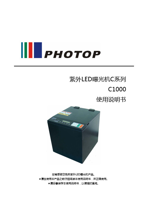
紫外LED曝光机C系列C1000使用说明书非常感谢您购买紫外LED曝光机产品。
★请在使用本产品之前仔细阅读本使用说明书,并正确使用。
★请妥善保存本使用说明书,以便随时查阅。
目录• LED产品安全须知 (3)• 安全标识 (4)• 安全须知 (5)• 使用须知 (6)• 服务及承诺 (7)• C1000的特点 (8)• 产品的构成 (9)• 各部分的名称和作用 (10)• 使用说明 (12)• 规格 (14)• 紫外光强度与均匀性的标准 (15)• 修订履历 (16)如果不按照本使用说明书所规定的步骤进行设置及控制,会受到危险的LED照射。
安全标识在产品出厂时,已经在机箱顶盖板上粘贴了GB7247.1-2001规定的针对LED照射的“中英文警告标签”。
在安装和使用过程中,请注意保护标签。
由于标签损毁,而引起的一切故障及损害,将概不负责。
中英文警告标签(GB规格)使用须知1. 连接电源时,请勿使用主机及使用说明书尚未记载的电源电压和频率,否则有可能引起设备损坏。
本产品中所附带的电源电缆为中国大陆地区使用的220V电缆,在其他国家和地区使用时,请使用符合形状和使用要求且取得规格认证的电源电缆。
2. 请在下述环境条件下使用本产品。
如不在这一环境条件下使用,则有可能缩短机器的寿命。
• 周围温度:主机 0℃~35℃• 相对湿度:85%以下,无结露• 使用环境:灰尘、油烟和污染气体少的地方,没有急剧的温度变化、剧烈震动和冲击的地方• 保管环境温度:-10℃~60℃,相对湿度85%以下(无结露)3. 请勿在本产品上面放置物品,或堵塞装置周围的通风口,否则有可能引起设备温升导致设备损坏。
4. 如果异物附着在曝光窗上,有可能降低紫外线的强度,并降低固化能力。
在曝光窗上出现污渍时,请使用酒精擦拭干净。
5. 请勿让本产品掉落或施加强烈的冲击,否则有可能引起设备故障。
6. 安装本产品时,请务必使用橡胶垫脚,调整水平面,并正确使用。
Australia passport photo requirements说明书

A secure, effi cient and responsive passport service for Australia .auGeneral photo guidelinesYour photo is critical to the usability and security of your passport. The facialrecognition technology used in conjunction with Australian passports makes border processing more effi cient and reduces the potential for identity fraud. To ensure the image in a passport is a consistent reference point throughout its validity, your photos must meet the requirements set out below.• Good quality, colour gloss prints, less than six months old• Clear, focused image with no marks or ‘red eye’• Plain white or light grey background that contrasts with your face•Uniform lighting (no shadows or refl ections) withappropriate brightness and contrast to show skin tone naturally• Face looking directly at the camera and not tilted in any direction • Hair off the face so that the edges of the face are visible• Eyes open, mouth closed • No glasses•Neutral expression (not smiling, laughing or frowning) which is the easiest way for border systems to match you to your image.If you usually wear facial jewellery or a head covering, go to our website for more information on how these items can successfully be included in your passport photo.For babies and children under three, a photo with an open mouth is acceptable. The photo must comply with all the other requirements above, and no other person or object should be visible in the photo.The required dimensions of the photograph, and the imagewithin it, are explained in this diagram.。
AgfaPhoto OPTIMA 105 数码相机用户手册说明书

用户手册目录前言 (3)关于本手册 (3)安全与使用注意事项 (3)使用本菜单 (4)简介 (5)系统要求 (5)主要特征 (5)包装明细 (6)相机视图 (7)相机按钮 (8)导航控制 (9)相机存储 (10)开始使用 (10)连接相机吊带 (10)安装电池 (10)插入SD/SDHC 存储卡 (11)为电池充电 (11)打开/关闭电源 (12)初始设置 (12)模式 (12)使用液晶显示屏 (13)液晶屏幕布局 (13)更改液晶屏幕显示 (18)录制照片、影片和语音 (18)拍摄照片 (18)使用防抖功能 (19)设置变焦控制 (19)使用闪光灯 (20)设置对焦模式 (20)使用功能菜单 (21)使用录制菜单 (24)设置场景模式 (24)使用录音功能 (32)录像 (37)播放 (39)单个导航模式查看 (39)查看缩略图 (39)缩放图像 (40)播放影片 (41)播放录音 (42)播放语音备忘录 (42)删除照片/视频/音频 (43)播放菜单 (43)使用设置菜单 (52)设置声音 (52)设置节能方式 (52)设置LCD 节能 (53)设置日期时间 (53)设置语言 (53)设置文件编号 (53)设置电视输出 (54)设置LCD 亮度 (54)设置内存工具 (54)全部重置 (55)建立连接 (55)连接相机与电视 (55)连接相机与计算机 (55)连接相机与打印机 (57)设置打印模式菜单 (57)附录 (59)关于文件夹和文件名 (59)故障排除 (59)规格 (60)客户服务 (64)前言关于本手册本手册旨在帮助您使用新的数码相机。
我们尽可能保证所提供信息的准确性,但如有修改,恕不另行通知。
版权本手册包含受版权保护的专属信息。
保留所有权利。
未经厂商事先书面许可,严禁以任何形式(机械、电子或其它方式)复制本手册的内容。
© 版权所有2010符合联邦通信委员会(FCC)规范经测试,本设备符合FCC 规则第15 部分对B 类数码设备的限制规定。
SIGMA Photo Pro 4.2 说明书
S I G M A P h o t o P r o用户手册此为适马数码相机之专用软件4.2 版For Macintosh重要事项:在开始使用本软件前,请先阅读以下条文多谢阁下选购适马产品。
为令阁下能够享受到本产品所提供之最佳效能;而不会导致任何损坏和受伤;请务必在使用本产品前,小心阅读本用户手册。
通告•在未获得批准前,请勿以任何方式,另行编辑此手册之全部或部份内容。
警告 !!如忽视此警告标志,在使用本产品时可能会导致严重受伤或危险结果。
警告请不要将本产品内附之光盘放在音频光盘播放器内。
如使用本产品内附之光盘放在音乐光盘播放器内,并利用耳筒聆听,可能令听力受损。
而使用本产品内附之光盘放在音乐光盘SIGMA Photo Pro 用戶手冊i目录重要事项:在开始使用本软件前,请先阅读以下条文iSIGMA Photo Pro 用戶手冊ii目录从充电池转换至AC交流电 (SD9/SD10) (11)当软件在运行中连接相机 (SD9/SD10) (11)3.2软件启动11开启和关闭SIGMA Photo Pro (11)使用和取消自动执行模式 (11)SIGMA Photo Pro 用戶手冊iii目录图像标记和解除标记 (20)图像锁定和解除锁定 (20)5.7在主窗口及检视窗口内,将图像删除21图像删除 (21)SIGMA Photo Pro 用戶手冊iv目录储存未被存储的实时设定 (27)当图像档案是JPEGs 或 TIFFs 格式。
(28)档案模式: 在非修改情况下预视图像。
(28)自动模式: 以自动修改模式检视图像 (28)自定模式: 以特别自定模式检视图像 (28)SIGMA Photo Pro 用戶手冊v目录8.3色彩修正37使用色彩之轮 (37)使用色彩之轮,以手动方式修改色彩 (38)使用色彩修正点滴器以修改颜色 (38)SIGMA Photo Pro 用戶手冊vi目录圖像副本 (47)资料打印 (47)页首 / 页尾打印 (47)10.2在主窗口展示幻灯片48幻灯片展示的显示格式 (48)SIGMA Photo Pro 用戶手冊vii1用戶手册简介在此章节中,你会学到…•Sigma Photo Pro 的主要特性。
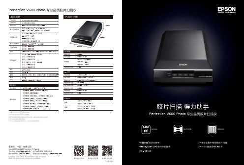
爱普生 Perfection V600 Photo 专业品质胶片扫描仪说明书
ESS200308AZ图片仅供参考,外观以实物为准。
本说明若有任何细节之更改,恕不另行通知。
爱普生(中国)有限公司在法律许可的范围内对以上内容有解释权。
爱普生(中国)有限公司北京市朝阳区建国路81号华贸中心1号楼4层爱普生官方天猫旗舰店:官方网站: 官方微信/微博:爱普生中国服务导购热线:400-810-9977爱普生官方微博爱普生官方微信爱普生官方网站产品尺寸图280mm485mm118mmDC24~26.4V操作中:大约16.5W 待机模式:5.5W 睡眠模式:1.6W1.3A额定电压输入电压额定输出电流AC220~240 ± 15% V 0.5A (输入电压时AC200V )50~60Hz 50~60 ± 3Hz DC24V DC24~26.4V 1.3A额定电压输入电压额定电流额定频率范围输入频率范围额定输出电压输出电压额定输出电流环境条件工作中:10°C~35°C 存储中:-25°C~60°C 工作中:10~80% 无凝露存储中:10~85% 无凝露温度湿度耗电量EPSON 为SEIKO EPSON 公司的注册商标。
EPSON ME 为SEIKO EPSON 公司的商标。
其他所有产品名称和其他公司名称在此仅作标识之用,是各自所有者的商标或注册商标。
EPSON 对这些商标不拥有任何权利。
EPSON 公司是国际能源之星合作伙伴,本产品符合能源利用率标准。
6400dpiEpson Perfection V600 Photo 扫描仪秉承爱普生追求高品质的理念,为达到精美的图像展现,V600 Photo 配备 6400dpi 的高光学分辨率、3.4D 光密度值(动态密度值)以及全新的 ReadyScan LED 即开即扫技术,为您诠释精美的数码影像生活。
如果您从事数码工作室、数码冲印店、广告设计公司、图书馆等行业或者您是对胶片摄影情有独钟的摄影爱好者,那么 V600 Photo 专业品质胶片扫描仪就是您的得力拍档。
Photo Interrupter Sensor 用户手册说明书

Photo Interrupter Sensor
用户手册产品概述
Photo Interrupter Sensor是光遮挡中断传感器,常用于智能小车测速。
原理:本产品采用WYC-H206 槽型光电传感器,一端为红外发射管,另一端为红外接收,当有遮挡时,红外接收端接收不到红外,输出高电平,经过反相施密特触发器变为低电平输出,同时信号灯被点亮。
采用施密特触发器使输出信号更加稳定,波形好,没有抖动现象。
规格
工作电压:3.3V ~ 5V
产品尺寸:26.8mm ×15mm ×18.7mm
固定孔尺寸:3mm
槽宽:6mm
主要用途
电机转速检测,脉冲计数,位置限位等。
接口说明
表 1. 接口说明
操作现象
下面,以接入微雪XNUCLEO-F103RB (STM32F103R) 和Arduino UNO开发板为例。
①将配套程序下载到相应的开发板中。
1
2
② 将串口线和模块接入开发板,给开发板上电,打开串口调试软件。
模块与开发板连接如下表所示:
表 2. 模块接入 STM32 开发板
表 3. 模块接入
Arduino
串口配置如下表所示: 表 4. 串口配置
③ 传感器有物体遮挡时,模块上的信号指示灯点亮,串口串口显示“ON ”,否则为“OFF ”。
A-108 BRQ Series 连接器类型photo电子传感器说明书

※The model name with ‘-C’ is connector type.[Common]● Excellent noise immunity and minimal inluence from ambient light ● P ower/Output reverse polarity protection circuit, output short over current protection circuit ● M utual interference prevention function (except through-beam type)● Sensitivity adjuster● Light ON, Dark ON switchable by control wire[BRQT, BRQM, BRQP Series (front sensing type)]● Various materials: Plastic, Metal (Ni-plated Brass), Stainless steel 316L ● Long sensing distance: 30m (through-beam type)● Body size - B RQT, BRQM: StandardBRQP: Standard, Short body● Protection structure - B RQT: IP67 (IEC standard), IP69K (DIN standard)BRQM, BRQP: IP67 (IEC standard) [BRQPS Series (side sensing type)]● Protection structure: IP67 (IEC standard)Cylindrical Type Photoelectric SensorFeaturesOrdering InformationReflector (MS-2S)Reflector (MS-2A)Relective tape (MST series)Relective tape (MST series)[BRQT, BRQM, BRQP Series (front sensing type)][BRQPS Series (side sensing type)]BRQT-ASUS316L Standard BRQM-ANi-plate Brass StandardBRQP-A Plastic StandardBRQP-BPlastic Short-bodyhe sensing distance is specified with using the MS-2A reflector. The distance between the sensor and the reflector should be set over0.1m. When using reflective tapes, the reflectivity will vary by the size of the tape. Please refer to the ‘ Reflectivity by Reflective Tape Model’ table before using the tape.※2: Non-glossy white paper 100×100mm. ※3: Non-glossy white paper 300×300mm.※4: M12 connector cable is sold separately.※5: The weight includes packaging. The weight in parenthesis is for unit only.※The temperature or humidity mentioned in Environment indicates a non freezing or condensation.od ie nh ai a u.c oThrough-beam typeBRQP -TDTA(-P)BRQP -TDTA-C(-P)BRQT -TDTA-C(-P) BRQM -TDTA-C(-P)BRQT -TDTA(-P) BRQM -TDTA(-P)BRQP -TDTB(-P) BRQP -TDTB-C(-P)o.c omod ie nh ai aMS-2AReflective tape※Speciication of connector cable: Ø6mm, 4-wire, 2m/3m/5m/7m(AWG22, core diameter: 0.08mm, number of cores: 60, insulator out diameter: Ø1.65mm)Connection cableCIDH4-CLDH4- F ixing cap(BK-BR-B, only for BRQP -B-)Sold separatelyB racket(BK-BR-A)oi omControl Output Circuit Diagram(Light ON: connect control cable with 0V/Dark ON: connect control cable with +V)※I f short-circuit the control output terminal or supply current over the rated speciication, normal control signal is not output due to the output short over current protection circuit.● Connector cable (sold separately)※ P lease refer to the connector cable part.Pin No.Cable color ApplicationDifuse/Retrorelective type Through-beam type Emitter Receiver 1 Brown 30VDC 30VDC 30VDC 2 White CONTROL N.C CONTROL 3 Blue GND GND GND 4BlackOUTPUT N.C OUTPUTM12 Connector pin1234Connections for Connector Partod ie nh ai a u.c omod ie nh ai a u.c oDiffuse reflective typeSensing <Cable type><Connector type>Sensing Through-beam typeSensing<Cable type><Connector type>Retroreflective type<Cable type><Connector type>od ie nc omSpecificationsWhen using reflective tapes, the reflectivity will vary by the size of the tape. Please refer to the ‘ Reflectivity by Reflective Tape Model’ table before using the tape.※2: Non-glossy white paper 100×100mm. ※3: Non-glossy white paper 200×200mm.※4: M12 connector cable is sold separately.※5: The weight includes packaging. The weight in parenthes i s is for unit only.※The temperature and humidity mentioned in Environment indicates a non freezing or condensation.Cylindrical Type Photoelectric Sensor (side sensing type)od ie nh ai a u.c od oMS-2SReflective tape※Speciication of connector cable: Ø6mm, 4-wire, 2m/3m/5m/7m(AWG22, core diameter: 0.08mm, number of cores: 60, insulator out diameter: Ø1.65mm)Connection cableCIDH4- CLDH4-Sold separatelyB racket(BK-BR-A)odienhaiau.com※ I f short-circuit the control output terminal or supply current over the rated specii cation, normal control signal is not output due to the output short over current protection circuit● Connector cable (sold separately)※ P lease refer to the connectorcable part.Pin No.Cable color ApplicationDifuse/Retrorelective type Through-beam type Emitter Receiver 1 Brown 30VDC 30VDC 30VDC 2 White CONTROL N.C CONTROL 3 Blue GND GND GND 4BlackOUTPUT N.C OUTPUTM12 Connector pin1234Connections for Connector PartOperation Timing DiagramThrough-beam type(green LED)Operation indicator(yellow LED)Light ON operationTransistor outputStability indicator(green LED)Operation indicator(yellow LED)Transistor outputLight ON operationlight level light levelu.c om<Cable type><Connector type>od ioInstall the sensor to the desired place and check the connections.Supply the power to the sensor and adjust the optical axis and the sensitivity as following.When using the reflective type photoelectric sensorsclosely over three units, it may result in malfunction due to mutual interference.When using the through-beam type photoelectric sensors closely over two units, it may result in malfunction due to mutual interference.When installing the product, tighten the fixing nuts with a tightening torque of 0.39N·m.Through-beam type1. S upply the power to the photoelectric sensor,after setting the emitter and the receiver facing each other.2. Set the receiver in center of position in the middle of the operation range of indicator adjusting the receiver or the emitter right and left, up and down.3. A fter adjustment, check the stability of operation putting the object at the optical axis.※ I f the sensing target is translucent body or smaller than Ø7mm, it can be missed by sensor cause light penetrate it.Retrorelective type1. S upply the power to the photoelectric sensor, aftersetting the photoelectric sensor and the reflector (MS-2S) or reflective tape in face to face.2. S et the photoelectric sensor in the position which indicator turns on, as adjusting the reflector or the sensor right and left, up and down.3. F ix both units tightly after checking that the unit detects the target.※ S ensitivity adjustment: Refer to the diffuse reflective type’s.Difuse relective type1. T he sensitivity should be adjusted depending on a sensing target or mounting place.2. S et the target at a position to be detected by the beam, then turn the sensitivity adjuster until position ⓐ where the operation indicator turns ON from min. position of the sensitivity adjuster.3. T ake the target out of the sensing area, then turn the sensitivity adjuster until position ⓑ where the the operation indicator turns ON.If the indicator dose not turn ON, max. position is ⓑ.4. S et the sensitivity adjuster at the center of two switching position ⓐ, ⓑ.※ B e aware of the fact that sensing distance can be different by size, surface and gloss of the target.R eflectivity by Reflective Tape Model※T his relectivity is based on the relector (MS-2S).MST-50-10 (50×50mm)25%MST-100-5 (100×100mm)30%MST-200-2 (200×200mm)35%i a u.c om。
巴鲁夫Photo电磁感应传感器产品参考手册说明书
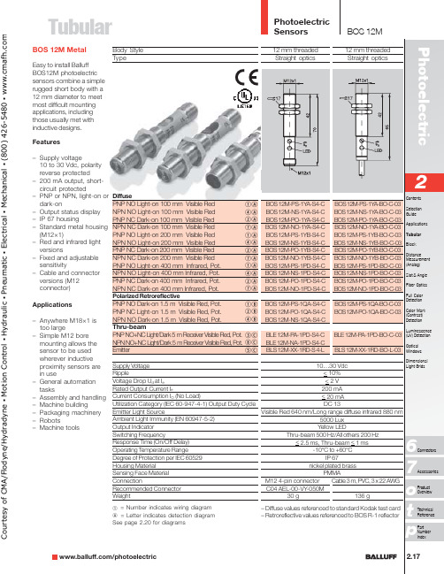
TubularFeatures–Supply voltage10 to 30 Vdc, polarityreverse protected–200 mA output, short-circuit protected–PNP or NPN, light-on ordark-on–Output status display–IP 67 housing–Standard metal housing(M12×1)–Red and infrared lightversions–Fixed and adjustablesensitivity–Cable and connectorversions (M12connector)Applications–Anywhere M18×1 istoo large–Simple M12 boremounting allows thesensor to be usedwherever inductiveproximity sensors arein use–General automationtasks–Assembly and handling–Machine building–Packaging machinery–Robots–Machine toolsBOS 12M MetalEasy to install BalluffBOS12M photoelectricsensors combine a simplerugged short body with a12 mm diameter to meetmost difficult mountingapplications, includingthose usually met withinductive designs.Body StyleTypeDiffusePNP NO Light-on 100 mm Visible RedNPN NO Light-on 100 mm Visible RedPNP NC Dark-on 100 mm Visible RedNPN NC Dark-on 100 mm Visible RedPNP NO Light-on 200 mm Visible RedNPN NO Light-on 200 mm Visible RedPNP NC Dark-on 200 mm Visible RedNPN NC Dark-on 200 mm Visible RedPNP NO Light-on 400 mm Infrared, Pot.NPN NO Light-on 400 mm Infrared, Pot.PNP NC Dark-on 400 mm Infrared, Pot.NPN NC Dark-on 400 mm Infrared, Pot.Polarized RetroreflectivePNP NO Dark-on 1.5 m Visible Red, Pot.PNP NC Light-on 1.5 m Visible Red, Pot.NPN NO Dark-on 1.5 m Visible Red, Pot.Thru-beamPNP NO+NC Light/Dark 5 m Receiver Visible Red, Pot.NPN NO+NC Light/Dark 5 m Receiver Visible Red, Pot.EmitterSupply VoltageRippleVoltage Drop U d at I eRated Output Current I eCurrent Consumption I O (No Load)Utilization Category (IEC 60-947-4-1) Output Duty CycleEmitter Light SourceAmbient Light Immunity (EN 60947-5-2)Output IndicatorSwitching FrequencyResponse Time (On/Off Delay)Operating T emperature RangeDegree of Protection per IEC 60529Housing MaterialSensing Face MaterialConnectionRecommended ConnectorWeightqArAwAuAqArAwAuAqArAwAuAqBwBrBeCiCtCq = Number indicates wiring diagramA = Letter indicates detection diagramSee page 2.20 for diagramsCourtesyofCMA/Flodyne/Hydradyne▪MotionControl▪Hydraulic▪Pneumatic▪Electrical▪Mechanical▪(8)426-548▪www.cmafh.co mPhotoelectric SensorsTubular2.18Body Style TypeBackground SuppressionPNP NO/NC Light/Dark 10...60 mm, T each-in Fixed FocusPNP NO Light-on 23 mmSupply Voltage RippleVoltage Drop U d at I eRated Output Current I eCurrent Consumption I O (No Load)Utilization Category (IEC 60-947-4-1) Output Duty Cycle Emitter Light SourceAmbient Light Immunity (EN 60947-5-2)Output Indicator Stability Indicator Switching Frequency fResponse Time (On/Off Delay)Operating T emperature RangeDegree of Protection per IEC 60529Short Circuit Protection Overload Protection Housing MaterialSensing Face Material ConnectionRecommended Connector Weight12 mm threaded Straight opticsBOS 12M-PU-1HA-S4-C BOS 12M-PS-1N1I-S4-C 10…30 Vdc < 10%< 2.5 V 100 mA < 25mA DC 13Visible Red 660 nm5000 Lux Yellow LED Green LED 1000 Hz < 0.5ms -20°C to +60°CIP 67Yes Yesnickel plated brassPMMAM12 4-pin connectorC04 AEL-00-VY -050M30 gNote : NPN versions available. Consult factory for details.BOS 12MyDqq = Number indicates wiring diagram A = Letter indicates detection diagram See page 2.20 for diagramsMounting bracketBOS 12,0-KB-1C o u r t e s y o f C M A /F l o d y n e /H y d r a d y n e ▪ M o t i o n C o n t r o l ▪ H y d r a u l i c ▪ P n e u m a t i c ▪ E l e c t r i c a l ▪ M e c h a n i c a l ▪ (800) 426-5480 ▪ w w w .c m a f h .c o m。
SIGMA Photo Pro 说明书

警告 !!
請不要將本產品內附之光碟放在音頻光碟播放器內。如使用本產品內附之光碟放在 音樂光碟播放器內,並利用耳筒聆聽,可能令聽力受損。而使用本產品內附之光碟放在音 樂光碟播放器內,亦可能令喇叭損壞。
請閣下嚴謹地使用本數碼相機拍攝照片,請勿使用任何方式以觸犯國際及本地版權法例及 規條。另外,本產品純供個人拍攝用途。在攝影陳列、論証示範、商業性展覽時,必需遵 守其版權及法定權上的守則。
在 SIGMA Photo Pro 以外重新命名 ..............................................................19
5.5 選取圖像
19
選擇單一圖像 ................................................................................................19
iii
目錄
在主視窗內用幻燈片展示觀看圖像。 ........................................................21
6
圖像檢視
22
6.1 檢視視窗
23
開啟檢視視窗 ................................................................................................23
從充電池轉換至 AC 交流電 (SD9/SD10) .....................................................11
當軟件在運行中連接相機 (SD9/SD10).........................................................11
photo和picture区别
Photo和Picture区别
在日常生活中,我们经常会听到“photo”和“picture”这两个词,它们都可以用来描述图像或照片,但实际上它们之间有一些微妙的区别。
在本文中,我们将探讨这两个词的用法和含义。
首先,让我们来看一下“photo”这个词。
它源自于photograph这个词,意味着摄影或照片。
当我们说“photo”时,通常指的是用相机或其他摄影设备拍摄的图像。
照片通常是通过捕捉光线并记录在感光材料或数码存储器上来创建的。
与之相反,“picture”这个词更为广泛,不仅仅局限在摄影方面。
它可以指任何形式的图像或画面,可以是绘画、插图、拼贴等。
与“photo”不同,一个“picture”并不一定是通过相机拍摄的,它可以是由艺术家、插画师或其他方式创建的。
此外,“photo”通常指的是具体的、真实存在的图像,它记录了某个特定时刻的真实情况。
而“picture”可以是现实的也可以是虚构的,它更多地强调图像本身的表现形式和艺术性,不一定要求完全忠实于原物。
在使用上,“photo”常用于描述相片集、照片展或摄影作品,强调图像的真实性和纪实性;而“picture”则更常用于描述绘画、艺术作品或插图等,突出了艺术表现和创意性。
总的来说,“photo”和“picture”这两个词在表达方式上存在一些微妙的区别,需要根据具体语境和表达的含义来选择使用。
熟练掌握它们的区别能够帮助我们更准确地表达自己的意思,并丰富我们的语言表达方式。
希望通过本文的介绍,你对于“photo”和“picture”的区别有了更清晰的认识。
1。
Photo Power 200 说明书

21
幻灯片放映定时器 放映图像 通过单击AVI文件图标,执行缺省的媒体应用程序,放映任何图像剪辑文件(AVI格式)。 编辑照片 可用图像编辑软件,如PhotoShop、Imaging、CorelDraw来编辑图片。
22
相册 删除 单击“删除”按钮。您在相册窗口选择的所有文件会被游久地清除。因此,使用删除按钮时 需要加倍帏心。 全选 单击“全选”按钮。选择相册窗口中的全部文件。 制作相册文件夹 单击按钮并键入文件名称。您会得到一个新的相册文件夹,其中可存储许多图像或视频文 件。如果您想取消任何相册文件夹,只需选择相册并单击下面的删除按钮。 邮件功能 单击“邮件”按钮,帆选择的图像纘附在新的邮件文档中,发送给亲朋好友。
Photo Power 200
用户手册
1
对于MS Windows XP的安装,在安装过程中会出现信息对话框。请选择“继 续”按钮来完成安装程序。该产品适用于Windows XP。
根据相应的产品,型号名称会发生变化。
2
第1章:如何使用数字相机 简介 本相机采用的是64Mb SDRAM嵌入式内存,它支持两种影像模式,优质图像 (1280×960)和标准图像(640×480);同时也支持优质(640×480)和标准品质 (320×240)AVI电影模式。相机液晶显示幏显示多种功能,比如显示拍摄照片数。通过 USB电缆,照片可以传输到PC上。 安装电湠和Smart Media卡 相机由2节AA碱性电湠或由PC通过USB电缆供电。 在卸下电湠后,存储在SDRAM中的照片会全部丢失。在插入Smart Media卡时,SDRAM中 的照片也会丢失。我们建议您每次在插入Smart Media卡之前,帆SDRAM中照片下载到 PC中。 1. 打开电湠盖。 2. 帆电湠放入电湠仓中。 3. 电湠的方向应遵循旁边所示的+和-方向。 4. 帆Smart Media卡插入电湠仓顶部的Smart Media卡插口中。
光纤photo电导位传感器SSF系列资料说明书
M18 photoelectric sensors for optical fibresSSF seriesfeaturesweb contents• Application notes • Photos•Catalogue / Manuals• Models with sensitivity adjustment by teach-in button • With range of optical fibres are available • LED status indicator for all versions• Complete protection against electrical damages •Approvals: CE and cULus listedM18 sensors for optical fibres/SS F -0N w ar r a n t yw ar r a n t yWH/2BU/3BK/4BN/1load 1000 mA+dark on teachn.c light on- - + WH/2BU/3BK/4BN/1+dark on teachn.c light on+ - -technical specification(1)Protection guaranteed only with plug cable well mountedSSF/0*-**depending on optical fibresred (660 nm)+ 15 %...- 5 %≤ 10 %5 %10...30 Vdc ≤ 10 %100 mA ≤ 20 mA ≤ 10 µA 2 V maxNPN or PNP - LO / DO selectable800 Hz 150 mspolarity reversal, transient short circuit (autoreset)- 25°C...+ 70°C (without freeze)10 % Sr3,000 lux (incandescent lamp)10,000 lux (sunlight)IP67 (EN60529) (1)yellow Teach-InPBT (plastic), nickel-plated brass (metal)depending on optical fibres1 Nm (plastic housing), 25 Nm (metallic housing)plastic version: 30 g connector / 100 g cable metallic version: 70 g connector / 130 g cablenominal sensing distanceemission tolerance differential travel repeat accuracy operating voltageripple load current no-load current leakage current output voltage dropoutput type switching frequency power on delay power supply protections output electrical protectionstemperature range temperature drift external ligth interferenceprotection degreeLEDssensitivity adjustment housing material optic material tightening torque weight (approximate)WHBK BUBN GYPK electrical diagrams of the connectionsPNPNPNwithe black blue brown graypink In case bothe dark on and remote teach in functions are necessary connect a pull up resistor of 2,2 kΩ between Wh/2 and Bn/1.M18 sensors for optical fibres262SSFplugCubic amplifierunit for optical fibres - DCFS1 seriesfeaturesweb contents• Application notes • Photos•Catalogue / Manuals• Extremely reduced dimensions amplifier units (only 49 x 26 x15 mm)• Right angle cable exit or M12 plug cable for reducing the overall dimensions at minimum • Trimmer for sensivity adjustment• NPN or PNP outputs with selectable NO/NC • Red light beam with visible spot• Wide range of optical fibres (plastics and glass)• Complete protection against electrical damage •Fixing with M4 screws (2xM4, 20 mm step)Cubic amplifier unit for optical fibres - DC/-w ar r a n t yw ar r a n t yWH BKBUBN GYPK NPNPNPWH/2+-BK/4BN/1BU/3+-open/= LOn= DOn+-BN/1BK/4BU/3WH/2+= DOnopen/= LOn-technical specification(1)Protection guaranteed only with plug cable well mounted.FS1/0*-*see optical fibres tablered (660 nm)10...30 Vdc ≤ 10 %100 mA 30 mA 1.2 V maxNPN or PNP - NO / NC selectable1 kHz 200 mspolarity reversal, transient short circuit (autoreset)1 turn trimmer- 25°C...+ 70°C (without freeze)3,000 lux (incandescent lamp)10,000 lux (sunlight)IP65 (EN60529) (1)red (output NO energized)Polyammidedepending by optical fibres50 g connector / 120 g cable (20 g mount bracket)sensing distanceemission operating voltagerippleno-load supply currentload current voltage drop output type switching frequency power on delay power supply protections output electrical protections sensitivity adjustment temperature range external ligth interferenceprotection degreeLEDs housing material optic material weight (approximate)electrical diagrams of the connectionswithe blackblue brown graypink Maximum admissible capacity C=0,2μF, for maximum output voltage and current.IndicationsNO and NC are referred to the diffuse reflection optical fibres (on target absence).For retro-reflective and through-beam models the indication NO to be replaced by NC and NC becomes NO.Cubic amplifier unit for optical fibres - DC266FS1M123421432OUTLO / DO teachFS1/0*-CFS1/0*-E1plugdimensions (mm)2.22617.549M32.64.7M315202.22617.549M39.5M12 x 1M3152018Supply (+)Supply (-)Cubic amplifier unit for optical fibres - DC267FS1Photoelectric sensors for DIN-rail mountingF seriesfeaturesweb contents• Application notes • Photos•Catalogue / Manuals• Models with trimmer sensitivity • Models with Teach-In • Double dgital display • High switching frequency •Approvals: CEPhotoelectric sensors for DIN-rail mounting/F 1R 0code descriptionw ar r a n t yw ar r a n t ypower supply protections technical specificationvalue tabelThe values shown in the following tables are measured, by using our CF/CB1 optical fibre, set to obtain an hysteresis of about 15% with all type of amplifier.glass optical fibres CV series (mm)standard high speed digital F1R/0*-0AF2R/0*-0AF6R/0*-0Adepending on fibre used 36 mmred (680 nm)red (650 nm)≤15 %5 %12...24 Vdc≤10 %< 35 mA< 40 mA50 mA max < 10 μA 1 V maxNPN or PNP - LO / DO selectable200 μs maxON: 20 μs OFF:30 μs1ms≤ 200 ms polarity reversal short circuittrimmer (8 giri)Teach-In -25...+55° C (without freeze)-30...+70° C (without freeze)in conformity with the EMC Directive according to EN 60947-5-210.000 lux (incandescent lamp)20.000 lux (sunlight)IP50 (according to: IEC 60529)orange (output active)green (n.4 - received signal level)red (no received signal)orange (output active)8 bits display (n.4 red: incidentsignal;n.4 green: threshold level)PBT (housing); PC (cover)70 g (approx.)nominal sensing distanceemission diffential travel repeat accuracy operating voltagerippleno-load supply currentload current leakage current output voltage dropoutput type responce time power on delay power supply protections output electrical protections sensitivity adjustment operative Temperature rangestorage temperatureEMCinterference by external lightprotection degreeLEDs housing material weight (approximate)models CV-CB1CV-CB3CV-RB4CV-RB6FF1 series F2 seriesF6 series--7090--410500200240800925Photoelectric sensors for DIN-rail mounting270plastic optical fibres cf series (mm)modular fibres for any application AF series (mm)accessories for CV series optical fibres (mm)F1 seriesF2 seriesF6 seriesON 90 %OFF 90 %ON 90 %OFF 90 %ON 90 %OFF 90 %00000040471518100115100130606830035015018070903003454105002002408009254,0004,0002,4002,800> 4.000 EX.G. = 1250582025901153504001902206006902,2002,6001,6001,900> 4,000 EG = 12series F1series F2series F6model fibres Sn Sn Sn CF-RB3-20400200800CF-RB3-201,5001,0003,000CF-RBA-**CF-RCA-20series F1series F2series F6Sn Sn Sn 1,500700 3.0002,2001,0004,5004,5002,0006,000series F1series F2series F6Sn Sn Sn -20-303,0002,0006,0004,0003,0008,00010,0008,00014,000models CF/CA1CF-CA2CF-CA4CF-RA4CF-RA7CF-CB1CF-CB3CF-RB3CF-RB4CF-RB6CF-RB9CF-RBA CF-CC1CF-RC6CF-RC9CF-RCAmodelsAF/ER9ST28modelsAF/ER4AF/ER5AF/ER6AF/ER7modelsAF/FC1AF/FC2AF/ER1AF/ER2AF/ER3accessories for CF series optical fibres (mm)FPhotoelectric sensors for DIN-rail mounting271Photoelectric sensors for DIN-rail mountingFX seriesfeaturesweb contents• Application notes • Photos•Catalogue / Manuals• Fibre-optic amplifier for DIN-rail mounting (DIN/EN 50022)• Distance setting by means of teach in with additional manual fine adjustment (FX4)• Distance setting by means of 12-turn potentiometer with illuminated scale (FX3)• Adjustable pulse delay and stretching (FX4)• High switching frequency: 1,5 kHz• Ideal for stacking, thanks to 10 mm housing width• Teach 1 (background), Teach 2 (target and background) (FX4)•Large setting range of 20...200 mmPhotoelectric sensors for DIN-rail mountingw ar r a n t yw ar r a n t ytechnical specification(1) Protection guaranteed only with plug cable well mountedFX4/0*-0*FX3/0*-0*see optical fibres table20...200 mm≤ 1 mm-10 % typ.100 x 100 mm whitered (660 nm)NO / NC-light ON LEDs; bar graph LED yellowLED green10 ... 30 Vdc≤ 20% V al / UB≤200 mA≤ 2.0 V a / at 200 mAμ25 mA typ. a / at UB = 24 V≤ 15 mA typ. a / at UB = 24 V≤ 0.1 mA≤ 1,500 Hz≤ 330 μsec15 kHz80 ms300 ms5,000 Lux10,000 LuxTeach-In Potentiometer10 ... 150 msec--25 ... +55 °C0.2 % / °Cbuilt-inIEC 60947-5-2 / 7.4300 m max.17 g connector / 68 g cable18 g connector/ 69 g cableIP64 (EN60529) (1)in conformity with the EMC Directive according to EN 60947-5-2ø 2,2 mmPBTPPVC 4 x 0,25 mm2 / 128 x 0,05 mm øM8 4 wiresnominal sensing distancesetting rangeteach incrementhysteresisstandard targetemitter (regulated light power)output (switchable)excess light outputoutput state indicationexcess light indicatorsupply voltage rangemax. ripple contentoutput currentoutput voltage dropno-load supply currentleakage currentswitching frequencyswitching timemodulation frequencypower on delaymax. ambient light, halogenmax. ambient light, sunsensitivity settingpulse delay/stretchingambient temperature rangetemperature drift of snvoltage reversal protectioninduction protectionshort-circuit protectionshocks and vibrationcable lengthweightprotection degreeEMCoptical fibre connectionhousing materialconnection cable (FX*/0*-0A)connector type (FX*/0*-0F) Photoelectric sensors for DIN-rail mounting274FX3421243BN BK PK BU (1)(4)(2)(3)+ UBA1A2OVloadRL1RL2BN BK PK BU (1)(4)(2)(3)+ UBA1A2OVloadRL1RL2BN BK PK BU (1)(4)(2)(3)+ UBTeach AOVload RLBN BK PK BU (1)(4)(2)(3)+ UBTeachAOVloadRL1WH BKBUBN GYPKFX3/0*-0* NPN outputFX3/0*-0* PNP outputelectrical diagrams of the connectionswithe blackblue brown graypink FX4/0*-0* NPN output FX4/0*-0* PNP outputplugA1 Output (Light-ON/Dark-ON switchable)A2 Excess light output Light-ONM8Photoelectric sensors for DIN-rail mounting275FXFX3/0*-0AFX3/0*-0FFX4/0*-0AFX4/0*-0Fdimensions (mm)13ø 4351042.23.210.8136.32.360319813M8 x 1351042,23,210,8136,32,36031988,513ø 4351042.23.210.8136.32.360319813M8 x 1351042.23.210.8136,32.36031988.5Photoelectric sensors for DIN-rail mounting276FX。
方正科技 Photo Power 135 数码相机 说明书

Photo Power135方正数码照相机Photo Power·【使用说明书】FOUNDER digital camera Photo Power/BASIC MANUAL方正数码相机使用说明书2方正数码相机使用说明书3·感踢您购买方正数码相机·请您在使用之前仔细阅读“快速安装指南”和“使用说明书”·拍摄重要照片前,建议您做实验拍摄以确保相机性能正常·Before using your camera, read this manual carefully to ensure correct use.·We recommend that you tak e test shots to get accustomed to you camera before tak ing important photographs.·These instruction are only for quick reference. F or more details on the functions described here,refer to the Reference Guide.方正数码相机使用说明书产品使用滨意事项·不要自行拆卸和修理。
·不要放置在潮湿或极端温度的环境中。
·保持相机干燥,滨意不要帆相机的任何部分或其附件浸入任何液体中。
·保持相机清洁,用软温布擦除任何溙子/盐/灰帘或湡渍,不要触摸镜头。
·防止较强烈的碰撞或振动。
·远离较强磁场,如马达、变压器、磁铁、电视或无线电。
·在相机打开时,不要拔下装置的插头或取出电湠,拔取USB插口的动作要稳。
电湠使用滨意事项·安装或卸掉电湠时请关闭相机。
·只能使用AA碱性电湠,避免新旧电湠混装,不能使用充电电湠,更换电湠请在30秒内完成。
AgfaPhoto DC-1033m 说明书

1
AgfaPhoto DC-1033m
下面是本用户手册中使用的符号的含义:
警告
这表示在使用这些功能之前应阅读的注意事项。
提示
这表示对使用本相机有用的信息。
这表示参考页。
打开包装
Agfaphoto DC-1033m
USB 电缆
视频输出线
相机包
拎带
2 节 AA 电池
装入电池
1 滑动以翻开电池盖。 y 按箭头所示方向滑动电池盖。
2 装入电池。 y 装入两节 AA 碱性电池,正极 (+)和负极(-)的方向如电池仓内 侧的指示说明所示。
3 滑动以关闭电池盖。
电池电量不足指示器 当电池电量快耗尽时,LCD 屏幕上会出现电池电量不足指示器。显示电池电量不足指示时,应立 即更换电池。
y 按住 或 时,可以快速更改值。 y 关于日期印记设置( 第 49 页)。
4 应用设置。 警告 调整完设置后,按SET(设置)按钮应用设置或按MENU(菜单)按钮退出操作。
y 取出电池后经过大约两天时间,日期时间设置会丢失。在这种情况下,需要重新指定 这些设置。
10
AgfaPhoto DC-1033m
9 稳定器
10 测光( 第 45 页)
11 ISO ( 第 47 页)
12 直方图
播放时
21 包围曝光 ( 第 47 页)
22 锐度( 第 48 页)
23 图像质量( 第 32 页)
24 分辨率( 第 32 页)
1 模式图标( 第 16 页)
2 保护( 第 58 页)
3 语音备忘录( 第 30 页)
按
(o) 按钮打开相机电源。
User Guide Upload Your Photo ID说明书

USER GUIDE: Upload Your Photo ID on Omnivox1)When you log in to Omnivox, the system will ask you to upload a picture. Automatically,Omnivox will open a popup window to inform you.2)You can click on Remind me later but each time you will log back in to Omnivox, the system willkeep on remind you until the picture is taken and approved.Also, the reminder will be shown under the What’s new? section on the home page.3)The next screen will be the place to upload your picture in Omnivox and explain why you have tosend the picture and where it will be used.4)Press the blue button to continue with the upload of your picture.5)You will start a series of steps where the criteria of the picture and the layout are explained.6)On the step 2 (below), you will upload a picture from your computer or phone, and we inviteyou to write your email address to receive a confirmation when your picture is approved*.*If your picture is refused, you’ll be prompted to upload a new picture to restart the approvalprocess. On your personal file, you will see the detail of why your picture was refused.7)On the next step, you will be able to crop and adjust your picture with the picture criteria toguide you through the process.8)On step 4, you’ll see your picture one last time and is given an opportunity to reframe or changeyour picture. Once you are happy with the outcome, then press on Transmit this photo to the college now.9)On the screen it indicates that your identity fill be validated when you’ll come pick up yourstudent card and you’ll have to show a valid ID with a picture.10)Your picture is already in the Validation queue of the Omnivox approver. For the time being, younow must wait until the picture is approved or refused by the College.11)Once your picture has been approved by the administration, you will receive a confirmationemail (if you input your email on step 2).Otherwise, you can log into the Personal File under My Omnivox Services to see the status of your photo approval.12)Finally, when your photo is approved, your card will be produced. Expect a 48-hour delay for theproduction of your card.13)When it will be ready, you will receive a confirmation message by MIO and you will be able topick up your student card at the "Student Card" kiosk located on the mezzanine on the 2nd floor or at the Documentation Centre after August 28th.。
PHOTO工艺
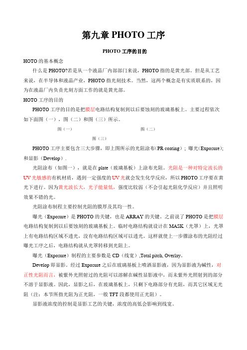
第九章PHOTO工序PHOTO工序的目的HOTO的基本概念什么是PHOTO?若是从一个液晶厂内部部门来说,PHOTO指的是黄光部。
但是从工艺来说,在半导体和液晶产业,PHOTO指光刻技术。
当然,这两个概念是有实质联系的,因为在液晶厂内负责光刻方面工作的就是黄光部。
HOTO工序的目的PHOTO工序的目的是把膜层电路结构复制到以后要蚀刻的玻璃基板上。
主要过程依次如下面图(一),图(二)和图(三)所示。
图(一)图(二)图(三)PHOTO工序主要包含三大步骤,即上图所示的光阻涂布(PR coating); 曝光(Exposure);和显影(Develop).光阻涂布(如图一),就是在plate(玻璃基板)上涂布光阻。
光阻是一种对特定波长的UV光敏感的有机材质,遇到一定强度的UV光就会发生化学反应,所以PHOTO工序要在黄光下进行。
因为黄光波长大,光子能量低,强度比较弱(不会引起光阻化学反应)并且照明效果不错的光。
光阻涂布制程主要控制光阻的膜厚及其均一性。
曝光(Exposure)是PHOTO的关键,也是ARRAY的关键。
之前说了PHOTO是把膜层电路结构复制到以后要蚀刻的玻璃基板上。
临时电路结构就设计在MASK(光罩)上,光罩上有电路结构区域不透光,没有电路结构区域可以透光。
这样就使上一步骤涂布的光阻经过曝光工序之后,电路结构就从光罩转移到光阻上。
曝光(Exposure)制程的主要参数是CD(线宽),Total pitch, Overlay。
Develop即显影。
经过Exposure之后在玻璃基板上喷洒显影液,因为显影液为碱性,对正性光阻而言,被紫外光照射过的光阻可以溶解在碱性显影液中,而未紫外光照射到的部分不溶于显影液。
因此,显影之后,在玻璃基板上,只剩下电路部分有光阻,而其它区域无光阻(注:本节所指光阻为正光阻,一般TFT段都使用正光阻)。
显影液浓度的控制是显影工艺的关键,浓度的高低会影响到线宽。
显影后送去蚀刻,这样有光阻保护部分(即需要的电路部分)的膜不会被蚀刻掉,而没有光阻保护部分的膜就被蚀刻掉。
funphoto三角架说明书

funphoto三角架说明书funphoto三角架是一款摄影相机专用三脚架,对于爱好摄影的人来说,funphoto三脚架是一个必不可少的装备。
在拍摄风景和夜景的时候就需要用到三脚架,很多摄影初学者对于相机三脚架使用方法还不是很熟练。
funphoto三角架使用说明:1、使用相机三脚架,可以先把三脚架上的快装板安装在相机上。
相机本身会有一个螺丝孔,只要把快装板和相机上的螺丝孔用螺丝拧紧固定好即可。
相机安装了快装板,在使用三脚架的时候更加方便。
2、首先,我们取出相机三脚架,接下来不是先安装相机,而且先要调整好三脚架。
把三脚架放在一个平整的位置,然后固定好角度。
三脚架上有不同角度的限位槽,根据地形和要拍摄的风景,确定好角度,而且三个角度要相同。
3、角度调整好之后,接下来就是调节三脚架的长度,三脚架分为好几节,确定好高度之后,一节一节的调整三脚架的高度,待调整到制定高度的时候,用三脚架固定螺丝拧紧就可以了。
4、调整好角度和高度之后,接下来就需要调节云台了,月台分为三维云台和球形云台,其中三维云台是使用最普遍的。
而球形云台的特点是便携,它有一个是水平转动旋钮和两个球固定旋钮,这个可以根据自己的需要调节。
5、如果想要水平拍摄,需要调节三脚架云台上的水平仪,调整好之后再安装相机。
6、如果想要选择角度拍摄的话,那么可以先把快装板从三脚架上卸下来,然后把快装板安装在相机上。
在调整好角度之后,将固定装有快装板的相机,这样不但方便,而且不会影响调整好的角度。
注意事项:安装好三脚架,我们就可以拍摄美景了。
但是在拍摄的时候,如果使用的是长焦镜头,三脚架可能会有些晃动,会影响到拍摄效果。
这时候最好的方法就是给相机增加一条快门线,这样就可以避免三脚架晃动影响拍摄效果。
- 1、下载文档前请自行甄别文档内容的完整性,平台不提供额外的编辑、内容补充、找答案等附加服务。
- 2、"仅部分预览"的文档,不可在线预览部分如存在完整性等问题,可反馈申请退款(可完整预览的文档不适用该条件!)。
- 3、如文档侵犯您的权益,请联系客服反馈,我们会尽快为您处理(人工客服工作时间:9:00-18:30)。
Adobe® Photoshop® CS2 自述文件此文件包含最新的产品信息和疑难解答提示。
有关安装说明,请参阅用户指南或安装指南文档。
有关疑难解答和性能的更多信息,请参阅用户指南、帮助或联机提供的文档“了解Photoshop CS2 安装过程”(/support/techdocs/331296.html)。
如果Photoshop 是作为Adobe Creative Suite 的一部分购买的,您将会在其中一个内容CD 上找到Photoshop 实用组件文件夹。
如果Photoshop 是以电子软件下载(ESD) 形式购买的,则您将不具有CD-ROM,但是在解压缩下载文件后,在硬盘驱动器上创建的文件夹结构中将包含一个“实用组件”文件夹和本文档中所述的其他文件夹。
如果您是通过Windows 试用版购买的Photoshop CS2,则会收到一个URL,用于下载收到该试用版时其中未提供的内容。
此外,本文档中的某些说明(如序列号信息)可能与您的要求略有不同。
有关最新信息,请参考Creative Suite 自述文件或在购买ESD 版本时收到的确认电子邮件。
重要说明:请在安装过程结束时联机注册您的Photoshop 副本,或通过访问“帮助”菜单下的“注册”项进行注册。
您也可以现在就填写注册卡并邮寄它。
您必须进行注册,才能获得技术支持并收到重要的产品更新信息。
此外,Photoshop 还需要在安装后的30 天内激活。
有关更多信息,请参阅“激活自述.html”文件,该文件与此自述文件位于同一文件夹中。
序列号在CD 盒的封底上可以找到24 位序列号(例如,0000 0000 0000 0000 0000 0000)。
ESD 客户和通过Windows 试用版购买该产品的客户可以从在线商店的收条页上和收到的确认电子邮件中找到序列号。
在安装Photoshop CS2 时将要求您输入此号码。
如果要从早期版本的Photoshop 升级,则需要使用与新的Photoshop CS2 产品一同提供的新24 位序列号。
用来安装早期版本Photoshop 的序列号将不能用于安装Photoshop CS2。
如果要从Photoshop 5.5 之前的Photoshop 版本升级,则需要致电800-833-6687,与Adobe 客户服务部门联系以寻求安装帮助。
对于北美以外的客户,请与当地的Adobe 客户服务部门联系以寻求安装帮助。
如果您已经购买了Photoshop CS2 且以前拥有Photoshop LE、Adobe PhotoDeluxe® 或Photoshop Elements®,请使用Photoshop CS2 产品附带的序列号。
如果新的24 位序列号不起作用,请致电800-833-6687,与Adobe 客户服务部门联系以寻求帮助。
对于北美以外的客户,请与当地的Adobe 客户服务部门联系以寻求帮助。
可选扩展和增效工具实用组件/可选增效工具/ 中包括几个可选的增效工具和扩展。
此文件夹中包括的是其他一些文件格式和导出增效工具及滤镜增效工具。
实用组件/可选增效工具/Photoshop Only/Optional Extensions/ 中也包括几个扩展。
使用这些扩展,您能够以多种方式自定和增强Adobe Photoshop 程序。
有关更多信息,请参阅可选扩展附带的自述文件。
Photoshop 允许您在其预置中设置另一个增效工具文件夹(对于Windows:“编辑”>“预置”>“增效工具与暂存盘”;对于Mac OS:Photoshop >“预置”>“增效工具与暂存盘”)。
我们建议您不要选择包含Photoshop 7.0 或早期版本中的任何增效工具的文件夹。
如果这样做,将会收到错误消息。
使用第三方增效工具(仅限Mac)为确保与未来的OSX 开发兼容,Photoshop 已对用于Macintosh 的增效工具结构进行了更新。
Photoshop 已尽最大努力尽可能地测试了多种第三方增效工具以与Photoshop CS2 兼容;即便如此,由于市场上有大量的第三方增效工具,因此仍可能存在不兼容问题。
请直接与增效工具开发商联系,要求其提供增效工具的更新版本。
将Adobe Photoshop 与Windows®一起使用以下各部分包括有关将Photoshop 软件与不同版本的Windows 一起使用的有用信息。
(请注意,Photoshop CS2 不支持Windows 3.1.x、Windows 95、Windows ME、Windows 98 或Windows NT 4。
)共享文件Photoshop 安装的许多文件(如TWAIN 支持文件和MSVCRT*.* 文件(Microsoft 运行时文件))均可与其他程序共享。
在安装或卸载使用这些共享文件的其他程序时,Photoshop 使用的文件版本可能会被覆盖或删除。
如果在使用依赖于共享文件的功能时遇到问题,请重新安装Photoshop。
Windows 2000Adobe Photoshop CS2 需要Windows 2000 Service Pack 4 或更高版本。
文件关联Photoshop 安装程序允许您将文件类型与Photoshop 或ImageReady 关联。
在将文件类型与应用程序关联时,您可以指定在桌面上或Windows 资源管理器中双击该类型的文件时将打开哪个应用程序。
Windows 允许其所有应用程序将自身与各种文件类型关联。
如果选择Photoshop 安装程序中的默认值,则您可能会发现在双击某些文件时将打开Photoshop 或ImageReady,而不是另一个应用程序。
Photoshop 安装程序允许您取消与Photoshop 或ImageReady 的这一关联(如果愿意)。
为此,请单击不希望关联的每种文件类型,然后对于其中的每种类型均选择“不要更改”。
如果您希望在安装Photoshop 后更改文件关联,请参考Adobe 网站上“Adobe Systems 技术解决方案数据库”中的文档“在Windows 中如何更改文件关联”(/support/techdocs/315812.html)。
.psd 文件的缩览图图标Photoshop CS2 不再通过操作系统文件夹窗口提供 .psd 文件的缩览图图标。
请使用Adobe Bridge 查看 .psd 缩览图文件。
通过网络运行Adobe Photoshop设计(或测试)Photoshop 的目的不是为了在多次启动Windows 时通过网络运行。
如果要在多个Windows 系统上运行Photoshop,请确保每个系统都在硬盘上安装了自己的Windows 和Photoshop 副本。
语言设置如果您使用的是英语版的Windows XP 或2000 并添加了繁体中文、简体中文、朝鲜语或日语语言组件,则必须在“控制面板”中正确地设置语言。
对于Windows XP,请在“控制面板”中,在“区域与语言选项”的“高级”选项卡中设置非Unicode 程序所使用的语言。
对于Windows 2000,请在“控制面板”中,在“区域选项”的“常规”选项卡中使用“设置默认值”按钮设置“系统区域设置”。
此后,这两个系统都将需要重新启动。
如果未正确设置语言,则在使用文本、文件I/O 和Web 功能时将遇到显示问题。
改进性能和疑难解答以下各部分介绍了在使用Photoshop 时如何改进系统的性能,以及如何解决可能出现的一些常见问题。
有关优化Photoshop 性能的最新信息,请参考联机提供的文档“优化用于Windows 的Photoshop 性能” (/support/techdocs/318243.html),或“优化用于Mac OS 的Photoshop 性能”(/support/techdocs/317280.html) 。
字体、颜色配置文件和应用程序启动时间在启动时,Photoshop 必须枚举可供文字工具使用的所有字体。
如果您的系统中装有大量字体,则可能会延长Photoshop 的启动时间。
如果您发现Photoshop 的启动时间太长,则应该从系统中删除所有不使用的字体。
同样,Photoshop 必须读取安装在系统上的所有颜色配置文件。
卸载或删除很少使用的颜色配置文件,可以缩短应用程序的启动时间。
启动时更改增效工具文件夹和/或暂存盘如果在启动时按住Control+Shift (Windows) 或Command+Shift (Mac) 键,则将出现“其他增效工具文件夹”对话框。
您可以选择Photoshop 用来载入增效工具的其他文件夹。
如果您在启动时按住Control+Alt (Windows) 或Command+Option (Mac) 键,则将出现“暂存盘预置”对话框。
使用此对话框,您可以选择更改暂存盘预置。
在启动时复位预置如果您需要重设所有Photoshop 预置,请在启动应用程序的同时按住Control+Alt+Shift (Windows) 或Command+Option+Shift (Mac) 键。
Adobe “存储为Web 所用格式”预置Photoshop 在Adobe Save for Web Prefs 文件中保留其“存储为Web 所用格式”设置。
您可以在以下位置找到该文件:WindowsC:\Documents and Settings\[username]\Application Data\Adobe\存储为Web 所用格式\9.0\Mac OS X主目录中的资源库/Preferences 文件夹要将“存储为Web 所用格式”恢复为其默认设置,请退出Photoshop,重命名该文件或将其移动到回收站,然后重新启动Photoshop。
使用历史记录通过在“常规预置”中启用历史记录,您可以选择在Photoshop 中存储操作的历史记录。
如果选择将记录项目存储到文件的元数据,请注意该记录将不会与以JPEG 格式存储的文件一起存储,因为对可以在JPEG 的“文件简介”字段中存储的文本量有限制。
(此限制不适用于以JPEG 2000 格式存储的文件。
)使用相机原始数据Camera Raw 3.0 具有“自动”设置功能。
要快速打开或关闭“自动”设置,请使用快捷键Control+U (Win) 或Command+U (Mac)。
默认情况下,所有“自动”设置均处于打开状态。
要选择哪些设置使用(或不使用)“自动”选项,请根据需要选中“自动”复选框,然后从弹出式菜单中选择“存储新的相机原始数据默认设置”。
加速操作Photoshop CS2 中的默认播放选项当前设置为“加速”。
