键盘扫描的VHDL实现
vhdl 4x4键盘扫描程序
WHEN "0100" =>
dyp_tmp <= "1100100";
WHEN "0101" =>
dyp_tmp <= "1001000";
BEGIN
row <= scan_key;
--dyp <= dyp_tmp;
ledct<="000001";
PROCESS(clk)
BEGIN
IF(clk'EVENT AND clk = '1')THEN
div_cnt <= div_cnt + 1;
WHEN "0110" =>
dyp_tmp <= "0001000";
WHEN "0111" =>
dyp_tmp <= "1100011";
WHEN "1000" =>
WHEN "0001" =>
dyp_tmp <= "1100111";
WHEN "0010" =>
dyp_tmp <= "0010010";
WHEN "0011" =>
key_code <= "1101";
WHEN "1011" =>
key_code <= "1110";
使用可编程逻辑器件实现矩阵键盘扫描模块的设计

使用可编程逻辑器件实现矩阵键盘扫描模块的设计给出了CPLD 部分模块的VHDL 语言实现和仿真波形。
在矩阵键盘的扫描、编码、输出完全不需CPU 控制的前提下,实现标准键盘和矩阵键盘双键盘同时使用。
在基于PC104 的便携式野外测试设备的设计中,键盘是常用的输入设备。
对于便携式设备野外工作时,一般使用小型(4×4)矩阵键盘就能满足设备的信息输入需要;室内调试时,使用标准PS2 键盘更方便、灵活。
一般的做法是保留PC104 的键盘接口用于接标准键盘,利用扩展I/O接口完成小矩阵键盘的扫描和输入。
这样做虽然可以实现设备双键盘同时工作的功能,却需耗费大量的CPU 处理时间扫描矩阵键盘,造成CPU 处理其他信息的能力下降。
而本文设计的基于CPLD 的矩阵键盘扫描模块能够很好地解决上述问题。
1 矩阵键盘扫描原理图1 给出了4×4 矩阵键盘的电路图,在图1 中KX[3..0]为扫描码输入,KY[3..0]为扫描码输出。
键盘扫描开始时,首先置KX[3..0]=“0000”;键盘扫描码寄存器和键盘扫描码缓存器Kreg[15..0]和Kscan[15..0]置成“1111111111111111”(全1为没有键按下,有键按下时至少有一位为0),一旦有键按下,KY[3..0]输出不全为“0”的扫描码触发键盘扫描功能开始键盘扫描,扫描开始后,依次将KX3、KX2、KX1、KX0 置“0”,分别将对应的4 组KY[3..0]输入值保存于Kscan[15..12]、Kscan[11..8] 、Kscan[7..4] 、Kscan[3..0]中,而后比较Kscan 和Kreg 的大小,如果Kscan 小于Kreg,将Kscan 保存于Kreg 中,重复上述扫描过程直到Kscan[15..0]各位输出全为“1”时,说明按下的键全部抬起,Kreg[15..0]中的每一个为“0”的位对应一个按下的键,保留扫描过程中的Kreg 最小值就可以处理组合键。
04陈阳 基于VHDL的键盘扫描及显示电路.

课程设计(论文)题目名称基于VHDL的键盘扫描及显示电路课程名称专业课程设计III学生姓名陈阳学号1041301004系、专业信息工程系、电子信息工程指导教师王少杰2013年11月05日运VHDL硬件描述语言和图形设计综合方法,实现了4×4键盘扫描电路的程序设计,通过运用QuartusⅡ软件平台生成电路符号,建立波形文件,设置输入端口,实现模拟仿真,得到仿真波形图。
FPGA/ CPLD 在数字系统设计中的广泛应用,影响到了生产生活的各个方面。
在FPGA/ CPLD 的设计开发中,VHDL 语言作为一种主流的硬件描述语言,具有设计效率高, 可靠性好, 易读易懂等诸多优点。
作为一种功能强大的FPGA/ CPLD 数字系统开发环境,Altera 公司推出的Quart us Ⅱ,为设计者提供了一种与结构无关的设计环境,使设计者能方便地进行设计输入、快速处理和器件编程,为使用V HDL 语言进行FPGA/ CPLD 设计提供了极大的便利。
矩阵键盘作为一种常用的数据输入设备,在各种电子设备上有着广泛的应用,通过7 段数码管将按键数值进行显示也是一种常用的数据显示方式。
在设计机械式矩阵键盘控制电路时,按键防抖和按键数据的译码显示是两个重要方面。
关键字:VHDL QuartusⅡ;数码管;FPGA/ CPLD;译码器摘要 (I)第2章方案设计 (1)1.1 题目分析 (1)2.2 矩阵键盘及显示电路设计路 (1)2.3 EDA技术的基本特征 (1)第3章电路设计 (2)2.1矩阵键盘及显示电路的实现 (2)2.2矩阵键盘及显示电路的电路符号 (2)2.3数码管显示译码模块设计 (2)第4章程序设计 (4)3.1键盘扫描模块程序、原理图及仿真波形 (4)3.2整体电路程序 (9)第5章仿真及结果 (11)第6章结束语 (12)参考文献......................................... . (13)第1章前言1.1EDA技术的介绍EDA是Electronic Design Automation的缩写,中文译为电子设计自动化,是现代电子设计技术的有力工具。
键盘扫描的VHDL实现

library ieee;use ieee.std_logic_1164.all;use ieee.std_logic_unsigned.all;entity jp isport(clk,start:in std_logic;kbcol:in std_logic_vector(3 downto 0); --行扫描信号kbrow:out std_logic_vector(3 downto 0); --列扫描信号seg7_out:out std_logic_vector(6 downto 0);--显示控制信号scan:out std_logic_vector(7 downto 0) --数码管地址选择控制信号);end jp;architecture one of jp issignal count,sta:std_logic_vector(1 downto 0);signal seg7:std_logic_vector(6 downto 0);signal dat:std_logic_vector(4 downto 0);signal fn:std_logic; --按键标志位,判断是否有键被按下beginscan<="00000001"; --只使用一个数码管显示--循环扫描计数器process(clk)beginif clk'event and clk='1'thencount<=count+1;end if;end process;--循环列扫描process(clk)beginif clk'event and clk='1'thencase count iswhen "00"=>kbrow<="0001";sta<="00";when "01"=>kbrow<="0010";sta<="01";when "10"=>kbrow<="0100";sta<="10";when "11"=>kbrow<="1000";sta<="11";when others=>kbrow<="1111";end case;end if;end process;--行扫描译码process(clk,start)beginif start='0'thenseg7<="0000000";elsif clk'event and clk='1'thencase sta iswhen "00"=>case kbcol iswhen "0001"=>seg7<="1111001";dat<="00011";when "0010"=>seg7<="1101101";dat<="00010";when "0100"=>seg7<="0110000";dat<="00001";when "1000"=>seg7<="1111110";dat<="00000";when others=>seg7<="0000000";dat<="11111";end case;when "01"=>case kbcol iswhen "0001"=>seg7<="1111000";dat<="00111";when "0010"=>seg7<="1011111";dat<="00110";when "0100"=>seg7<="1011011";dat<="00101";when "1000"=>seg7<="0110011";dat<="00100";when others=>seg7<="0000000";dat<="11111";end case;when "10"=>case kbcol iswhen "0001"=>seg7<="0011111";dat<="01011";when "0010"=>seg7<="1110111";dat<="01010";when "0100"=>seg7<="1111011";dat<="01001";when "1000"=>seg7<="1111111";dat<="01000";when others=>seg7<="0000000";dat<="11111";end case;when "11"=>case kbcol iswhen "0001"=>seg7<="1000111";dat<="01111";when "0010"=>seg7<="1001111";dat<="01110";when "0100"=>seg7<="0111101";dat<="01101";when "1000"=>seg7<="1001110";dat<="01100";when others=>seg7<="0000000";dat<="11111";end case;when others=>seg7<="0000000";end case;end if;end process;--产生按键标志位,用于存储按键信息fn<=not (dat(0) and dat(1) and dat(2) and dat(3) and dat(4));process(fn)beginif fn'event and fn='1'then --按键信息存储seg7_out <=seg7;end if;end process;end one;。
基于VHDL的键盘扫描电路设计教材

毕业论文(设计)题目:基于VHDL的键盘扫描电路设计系:机电工程系学生姓名:专业:电子信息工程班级:指导教师:起止日期: 2012.10.15——2013.01.06 2013年1 月6 日基于VHDL的键盘扫描电路设计(东海科学技术学院机电工程系,浙江舟山 316000)摘要随着科技的发展,时代的进步,生活的需要,在我们生活的很多地方领域,都有键盘的应用,而且它的应用非常广,当然键盘扫描的方法也有很多种。
键盘是单片机系统设计中一种主要的信息输入接口,合理的设计,不仅可以节省系统的设计成本,更可以使仪器设备的操作变得更为简单、方便、快捷,很大程度上提高系统综合性能。
随着信息产业和微电子技术的发展,很多系统设计技术已经成为信息产业最热门的技术之一,在很多地方上都有应用,比如航空航天、医疗保健、通讯、广播、工业、测量测试等很多热门领域。
并且随着工艺的进步和技术的发展,向更广泛的应用领域扩展。
本次设计主要是运用VHDL硬件描述语言和图形设计综合方法,在MAX+PLUSⅡ软件平台的环境下建立波形文件,生成电路符号,设置输入端口,实现程序的模拟仿真,得到仿真波形图,才完成了键盘扫描电路的程序设计。
这个电路设计是一个关于小型的计算器的键盘按键电路的设计,主要由5个部分组成,它们分别为分频器电路、键盘扫描计数器电路、按键检测电路、按键抖动消除电路和键盘编码电路。
本次设计主要是设计一个4×4矩阵式的键盘扫描电路,它具有列扫描和行扫描的功能,有2个输入端口,分别为clk和col,同时也有2个输出端口,分别为row和bianma,按下按键的数据通过端口行、列线输入到FPGA芯片中去,FPGA芯片内部的扫描模块会将数据传送到编码器中进行编码,最终完成本次电路的设计。
在生活中是这种小型的计算器是非常常用的,虽然体型很小,但却被广泛的使用,很多其他的东西都是在这种小型的计算器的键盘的基础上设计的。
关键词:键盘扫描;VHDL;MAX+PLUSⅡ;仿真AbstractWith the development of science and technology, the progress of the times, the need of the life, we live in a lot of place fields, there are keyboard application, but its application is very wide, of course, the keyboard scanning method also has a lot of, the keyboard is the design of single-chip microcomputer system a main information input interface, a reasonable design, not only can save the design cost of system, it can make the equipment operation more simple, convenient, fast, greatly improve the overall system performance. With the development of information industry and the development of microelectronic technology, a lot of system design technology has become the information industry one of the hottest technologies, in many places have applications, such as aerospace, medical care, communication, broadcast, industrial, testing and many other hot areas. And with the technology progress and technology development, to the more widespread application domain expansion.The main design is the use of VHDL hardware description language and graphic design method in the MAX+PLUS software platform, established under the wave file, generating circuit symbols, set the input port, procedures to achieve the simulation, get the simulation waveform, to complete the keyboard scanning circuit design program. The circuit design is a small calculator keyboard circuit design, mainly is composed by 5 parts, which respectively as the divider circuit, keyboard scan counter circuit, key detection circuit, key jitter elimination circuit and keyboard coding circuit. The design is the design of a 4 x 4 matrix keyboard scanning circuit, it has a column scanning and scanning function, having 2 input ports, respectively CLK and col, but also has 2 output ports, respectively row and bianma, press the key data through the port line, line input to the FPGA chip, FPGA chip inside the scanning module can transmit data to the encoder for encoding, the final completion of the circuit design. In life is such a small calculator is very common, though very small in size, but it is widely used, many other things are in such a small calculator keyboard design based on.Key words:keyboard scan; VHDL ; MAX+PLUS Ⅱ;simulation目录第1章绪论 (1)1.1研究的意义和背景 (1)1.2键盘在国内外的发展状况 (1)1.3本课题研究的主要问题 (2)第2章键盘扫描电路总体设计 (3)2.1 设计工具的简介 (3)2.1.1VHDL硬件描述语言 (3)2.1.2MAX+PLUSⅡ的简介 (3)2.1.3FPGA芯片的介绍 (5)2.2键盘扫描电路的基本流程 (7)2.3键盘扫描电路的原理框图 (8)第3章键盘扫描电路的模块电路设计 (10)3.1分频器电路 (10)3.2键盘扫描计数器电路 (11)3.3按键检测电路 (12)3.4按键抖动消除电路 (13)3.5 键盘编码电路 (13)3.6 扫描电路总电路图 (14)第4章顶层设计 (16)4.1端口定义 (16)4.2仿真结果 (17)4.3电路符号 (17)第5章软件调试 (18)5.1 分频器电路中 (18)5.2键盘扫描计数器电路中 (19)5.3按键检测电路中 (20)5.4按键抖动消除电路中 (20)5.5键盘编码电路中 (21)总结 (23)致谢 (24)[参考文献] (25)附录 (26)第1章绪论1.1研究的意义和背景键盘与我们的生活息息相关,可以说是在我们的生活中是无处不在的,比如说手机键盘、电视机的键盘、电脑的键盘等等。
实验四 译码扫描显示电路VHDL输入设计

实验二:计数器动态扫描实验一实验目的熟悉译码扫描动态显示的工作原理、设计过程和实现方法。
二实验内容与要求学习用VHDL设计译码扫描动态显示电路,完成编译、综合、适配、仿真和实验箱上的硬件测试。
三实验平台(1)硬件:计算机、GX-SOC/SOPC-DEVLABCycloneII EP2C35F672C8核心扳(2)软件:Quartus II四实验原理通过动态扫描一组4BIT 的输入,有控制开关控制数据的流向,即在哪个数码管上显示,在允许的条件产生后,扫描记录响应位置上的输入数据(开关选择),将结果动态地显示在共阴数码管上。
在能满足人眼要求的一定的扫描频率下,对数据进行动态显示。
五程序--显示电路--显示电路整合--ledscan.vhd 4 digit bcd-to-7 segment scan displaylibrary ieee ;use ieee.std_logic_1164.all;use ieee.std_logic_unsigned.all;entity ledscan isport(clk : in std_logic; --synchronousenable : in std_logic; --scan clockdata_bcd :in std_logic_vector(3 downto 0);--input bcdctrl : in std_logic_vector(2 downto 0);---ctrl the order of inputi.e. bcd_dataledseg : out std_logic_vector(6 downto 0);--output to 7 segmentledcom : out std_logic_vector(5 downto 0));--7 segment enableend ledscan;architecture behavior of ledscan issignal com_clk : std_logic_vector(2 downto 0);signal bcd_led : std_logic_vector(3 downto 0);signal data2show : std_logic_vector(23 downto 0);component comcounport(clk : in std_logic;--synchronouse clockenable : in std_logic;--scan clockcomclk : out std_logic_vector(2 downto 0));--output count end component;component com_encodeport(com_clk : in std_logic_vector(2 downto 0);--input countledcom : out std_logic_vector(5 downto 0));--output encodeend component;component bcd_muxport(com_clk : in std_logic_vector(2 downto 0);--input countbcd_data : in std_logic_vector(23 downto 0);--input display databcd_led : out std_logic_vector(3 downto 0));--output to 7 segment end component;component bcd_7segport(bcd_led : in std_logic_vector(3 downto 0);--input bcdledseg : out std_logic_vector(6 downto 0));--output to 7 segment end component;begininput_control:process(clk)beginif (clk'event and clk='1') thenif ctrl="000" thendata2show(3 downto 0)<=data_bcd;-- first value to showelsif ctrl="001" thendata2show(7 downto 4)<=data_bcd;-- 2nd value to showelsif ctrl="010" thendata2show(11 downto 8)<=data_bcd;-- 3rd value to showelsif ctrl="011" thendata2show(15 downto 12)<=data_bcd;-- 4th value to showelsif ctrl="100" thendata2show(19 downto 16)<=data_bcd;-- 5th value to showelsif ctrl="101" thendata2show(23 downto 20)<=data_bcd;-- 6th value to showelsedata2show<="000000000000000000000000";end if;end if;end process ;u0: comcoun port map (clk=>clk,enable=>enable,comclk=>com_clk);-- 7 segment com scan counteru1: com_encode port map(com_clk=>com_clk,ledcom=>ledcom);-- 7 segment com scan counter--u1: com_encode port map (com_clk,ledcom); --7 segment com encode u2: bcd_mux port map (com_clk=>com_clk,bcd_data=>data2show,bcd_led=>bcd_led);--multiplexeru3: bcd_7seg port map (bcd_led=>bcd_led,ledseg=>ledseg); --bcd to7 segment encoderend behavior;--七段显示扫描电路--comcoun.vhd 7 segment com scan counterlibrary ieee ;use ieee.std_logic_1164.all;use ieee.std_logic_unsigned.all;entity comcoun isport(clk : in std_logic;--synchronouse clockenable : in std_logic;--scan clockcomclk : out std_logic_vector(2 downto 0));--output countend comcoun;architecture behavior of comcoun issignal q : std_logic_vector(2 downto 0);--internal counted signal beginfscan:process(clk)beginif (clk'event and clk='1') thenif (enable='1') thenif q>=6 thenq<="000";--initial counterelseq<=q+1;--countingend if;end if;end if;end process fscan;comclk<=q; --output internal countend behavior;--计数译码电路 -- 6 共阴--com_encode.vhd 7 segment com encoderlibrary ieee ;use ieee.std_logic_1164.all;entity com_encode isport(com_clk :in std_logic_vector(2 downto 0);--input countledcom :out std_logic_vector(5 downto 0));--output encodeend com_encode;architecture behavior of com_encode isbeginledcom<="000001" when com_clk="001" else"000010" when com_clk="010" else"000100" when com_clk="011" else"001000"when com_clk="100" else"010000"when com_clk="101" else"100000";end behavior;--bcd_mux.vhd multiplexer of bcd-selectionlibrary ieee ;use ieee.std_logic_1164.all;entity bcd_mux isport(com_clk : in std_logic_vector(2 downto 0);--input countbcd_data :in std_logic_vector(23 downto 0);--input display data bcd_led : out std_logic_vector(3 downto 0));--output to 7 segment end bcd_mux;architecture behavior of bcd_mux isbeginbcd_led<=bcd_data(3 downto 0) when com_clk="001" elsebcd_data(7 downto 4) when com_clk="010" elsebcd_data(11 downto 8) when com_clk="011" elsebcd_data(15 downto 12)when com_clk="100" elsebcd_data(19 downto 16)when com_clk="101" elsebcd_data(23 downto 20)when com_clk="110" else"----";end behavior;--bcd对应七段显示器编码电路--bcd_7seg.vhd bcd to 7 segment encoderlibrary ieee ;use ieee.std_logic_1164.all;entity bcd_7seg isport(bcd_led :in std_logic_vector(3 downto 0);--input bcdledseg : out std_logic_vector(6 downto 0));--output to 7 segment end bcd_7seg;architecture behavior of bcd_7seg isbeginwith bcd_led selectledseg<="0111111" when "0000",--0"0000110" when "0001",--1"1011011" when "0010",--2"1001111" when "0011",--3"1100110" when "0100",--4"1101101" when "0101",--5"1111101" when "0110",--6"0100111" when "0111",--7"1111111" when "1000",--8"1101111" when "1001",--9"1110111" when "1010",--A"1111100"when "1011",--b"0111001"when "1100",--c"1011110" when "1101",--d"1111001"when "1110",--E"1110001" when "1111",--F"0000000" when others;end behavior;六引脚定义及代码图2-1引脚定义代码:# Copyright (C) 1991-2008 Altera Corporation# Your use of Altera Corporation's design tools, logic functions # and other software and tools, and its AMPP partner logic# functions, and any output files from any of the foregoing# (including device programming or simulation files), and any# associated documentation or information are expressly subject # to the terms and conditions of the Altera Program License# Subscription Agreement, Altera MegaCore Function License# Agreement, or other applicable license agreement, including,# without limitation, that your use is for the sole purpose of# programming logic devices manufactured by Altera and sold by# Altera or its authorized distributors. Please refer to the# applicable agreement for further details.# Quartus II: Generate Tcl File for Project# File: ACOUNT10.tcl# Generated on: Tue Nov 03 11:40:42 2009# Load Quartus II Tcl Project packagepackage require ::quartus::projectset need_to_close_project 0set make_assignments 1# Check that the right project is openif {[is_project_open]} {if {[string compare $quartus(project) "ACOUNT10"]} {puts "Project ACOUNT10 is not open"set make_assignments 0}} else {# Only open if not already openif {[project_exists ACOUNT10]} {project_open -revision ACOUNT10 ACOUNT10} else {project_new -revision ACOUNT10 ACOUNT10}set need_to_close_project 1}# Make assignmentsif {$make_assignments} {set_global_assignment -name FAMILY "Cyclone II"set_global_assignment -name DEVICE EP2C35F672C8set_global_assignment -name ORIGINAL_QUARTUS_VERSION 8.0set_global_assignment -name PROJECT_CREATION_TIME_DATE "11:03:58 NOVEMBER 03, 2009"set_global_assignment -name LAST_QUARTUS_VERSION 8.0set_global_assignment -name USE_GENERATED_PHYSICAL_CONSTRAINTS OFF -section_id eda_palaceset_global_assignment -name DEVICE_FILTER_PACKAGE FBGAset_global_assignment -name DEVICE_FILTER_PIN_COUNT 672set_global_assignment -name DEVICE_FILTER_SPEED_GRADE 8set_global_assignment -name MIN_CORE_JUNCTION_TEMP 0set_global_assignment -name MAX_CORE_JUNCTION_TEMP 85set_global_assignment -name VHDL_FILE com_encode.vhdset_global_assignment -name PARTITION_NETLIST_TYPE SOURCE -section_id Topset_global_assignment -name PARTITION_COLOR 14622752 -section_id Top set_global_assignment -name LL_ROOT_REGION ON -section_id "Root Region"set_global_assignment -name LL_MEMBER_STATE LOCKED -section_id "Root Region"set_global_assignment -name VHDL_FILE comcoun.vhdset_global_assignment -name VHDL_FILE COUNT10a.vhdset_global_assignment -name VHDL_FILE bcd_7seg.vhdset_global_assignment -name VHDL_FILE clkgen.vhdset_global_assignment -name VHDL_FILE ACOUNT10.vhdset_global_assignment -name VECTOR_WAVEFORM_FILE warefare.vwfset_global_assignment -name INCREMENTAL_VECTOR_INPUT_SOURCE warefare.vwfset_instance_assignment -name PARTITION_HIERARCHY root_partition -to | -section_id Topset_location_assignment PIN_P25 -to clkset_location_assignment PIN_F6 -to Clrset_location_assignment PIN_B22 -to enset_location_assignment PIN_H23 -to LEDCOM[5]set_location_assignment PIN_G26 -to LEDCOM[4]set_location_assignment PIN_G25 -to LEDCOM[3]set_location_assignment PIN_G24 -to LEDCOM[2]set_location_assignment PIN_G23 -to LEDCOM[1]set_location_assignment PIN_P18 -to LEDCOM[0]set_location_assignment PIN_F26 -to LEDSEG[6]set_location_assignment PIN_F25 -to LEDSEG[5]set_location_assignment PIN_J20 -to LEDSEG[4]set_location_assignment PIN_J21 -to LEDSEG[3]set_location_assignment PIN_F23 -to LEDSEG[2]set_location_assignment PIN_F24 -to LEDSEG[1]set_location_assignment PIN_E25 -to LEDSEG[0]set_location_assignment PIN_B21 -to EN6# Commit assignmentsexport_assignments# Close projectif {$need_to_close_project} {project_close}}七仿真图2-2 创建VHDL文件图2-3 PIN口设置图2-4 创建VERILOG文件图2-5 运行八导入程序图2-7 下载图2-8 实验结果。
基于VHDL的键盘扫描及显示电路毕业设计
基于VHDL的键盘扫描及显示电路一、工作原理:可编程器件的KEY_HANG[3..0]行信号输出端不停循环输出“1110”“1101”“1011”“0111”。
当没有键按下时可编程器件的KEY_LIE[3..0]列信号输入端检测到的是“1111”。
当有按键按下时,如按下1,此时KEY_HANG[3..0]行信号输出为“0111”,即KEY_HANG[3..0]的3管脚为“0”,可由电路看出,此时输入端KEY_LIE[3..0]检测到的将是“0111”。
KEY_LIE[3..0]的3管脚为0,可以在编写程序时,将输出信号KEY_HANG[3..0]与输入信号KEY_LIE[3..0]同时判断,比如可以认为当数据“KEY_HANG&KEY_LIE”为“01110111”时,可译码成数据1,。
同理可得其他按键的编码。
根据不同数据的编码译成不同的数据。
名称IO属性描述备注clk in 输入时钟,1K和40K频率KEY_HANG[3..0]out矩阵键盘的扫描输入端口KEY_LIE[3:0] in矩阵键盘的扫描输出端口START out 数据输出标志DISP DATA[6..0]out 数码管译码显示译码输出7bitDASP SEL[1..0] out数码管扫描输出2bitCLK_1K CLK_40K CLK_1K STARTKEY_HANG[3..0] CLE_40K DATA_P[7..0]DISP DATA[6..0] KEY_LIE DASP SEL[1..0]二、设计思路:1.循环输出行信号,检测列信号输入,将行列信号相并。
2.译键值。
3.去抖动。
在译没一个键值后,为了防止抖动,加了一个计算环节,一旦检测到列信号后,译码,紧跟着进入计数环节,此时键抖动不会进入其他环节,这样可以防止抖动。
4.数码管译码、循环显示。
电路的具体功能罗列如下:1) 采用4×4矩阵键盘作为操作数和操作符的输入设备。
VHDL独立按键扫描

library ieee;use ieee.std_logic_1164.all;use ieee.std_logic_arith.all;use ieee.std_logic_unsigned.all;entity key isport(A,B,C,D:in std_logic;--键盘模块的四个外接按键,编号依次是A、B、C、D clk_key:in std_logic;--时钟信号,作为消抖计时key_value:out std_logic_vector(1 downto 0);--输出按键值out_clk:out std_logic:='0'--键值传送脉冲信号,宽度为8个时钟信号周期_| |____);end entity;architecture art of key issignal key_value_1:std_logic_vector(1 downto 0);signal abcd:std_logic_vector(3 downto 0);beginabcd<=A&B&C&D;--------------------------------------------------------------------process(clk_key)variable counter: std_logic_vector(15 downto 0);variable state:integer range 4 downto 0;beginif rising_edge(clk_key)thencase state iswhen 0 => if (abcd(0)='0' or abcd(1)='0' or abcd(2)='0'or abcd(3)='0') thenstate:=1;else state:=0;end if;when 1 => if counter>="1111111111111110" thenstate:=2;counter:="0000000000000000";else counter:=counter+1;state:=1;end if;when 2 => if abcd(0)='0' or abcd(1)='0' or abcd(2)='0'or abcd(3)='0' thencase abcd iswhen "0111"=>key_value_1<="00";state:=3;when "1011"=>key_value_1<="01";state:=3;when "1101"=>key_value_1<="10";state:=3;when "1110"=>key_value_1<="11";state:=3;when others=>state:=0;end case;else state:=0;end if;when 3 => if (abcd(0)='0' or abcd(1)='0' or abcd(2)='0'or abcd(3)='0')thenif counter>="0000000000000011"then -----------------------------------------counter:="0000000000000000";out_clk<='1';else counter:=counter+1;end if;state:=3;elsestate:=4;out_clk<='1';end if;when 4 => if counter>="0000000000000111" thenstate:=0;counter:="0000000000000000";out_clk<='0';else counter:=counter+1;state:=4;end if;end case;end if;end process;--------------------------------------------------------------------------------process(key_value_1)beginif clk_key'event and clk_key='0' thenkey_value<=key_value_1;end if;end process;end art;。
可编程器件与硬件描述语言VHDL_PS2键盘

PS2键盘扫描总原理图:说明:总的原理图中共包含4个模块,分别是PS2键盘按键数据读取模块KEY_DATA、数据转换模块CONVERT、数码管显示模块LED、液晶显示模块LCD,以下就各个模块分别作进一步的说明:(1)PS2键盘按键数据读取模块KEY_DATA宏模块图:VHDL代码:library IEEE;use IEEE.STD_LOGIC_1164.ALL;use IEEE.STD_LOGIC_ARITH.ALL;use IEEE.STD_LOGIC_UNSIGNED.ALL;entity KEY_DATA isport(sys_clk : in STD_LOGIC;k_data : in STD_LOGIC;k_clock : in STD_LOGIC;reset : in STD_LOGIC;data : out STD_LOGIC_VECTOR(7 DOWNTO 0);request : out STD_LOGIC);end KEY_DATA;architecture Behavioral of KEY_DATA issignal tmp : STD_LOGIC_VECTOR(11 downto 0) :="000000000000"; --记录一帧的信号signal now_kbclk,pre_kbclk : std_logic;signal scan : STD_LOGIC_VECTOR(10 DOWNTO 0);beginprocess(reset,k_clock,sys_clk)beginif reset='1' then tmp<="000000000000";elsif sys_clk'event and sys_clk='1' thenpre_kbclk <= now_kbclk;now_kbclk <= k_clock;if(pre_kbclk > now_kbclk) then --检测到ps2键盘时钟的下降沿if tmp(0)='0' thentmp <= k_data & "01111111111"; --开始存入数据,"01111111111"中的"0"用于之后判断一帧数据是否读取完毕elsetmp <= k_data & tmp(11 downto 1); --存数据end if;end if;end if;end process;process(tmp)beginif tmp(0) = '0' then --一帧数据读取完毕scan <= tmp(11 downto 1);data <= scan(8 downto 1);request<='1';elsedata <="00000000";request<='0';end if;end process;end Behavioral;管脚说明:reset为复位信号,高电平有效,使输出置0;sys_clk为系统时钟信号(25MHz);k_clock为键盘时钟信号;k_data为键盘数据信号;data(7:0)为输出信号,表示读取的键盘扫描码;request也为输出信号,该管脚为”1”表示一次按键的扫描码已读取完毕,用以通知后续转换电路将扫描码转换为ASCII码。
基于VHDL的键盘扫描及显示电路设计
取消所有断点。
断点设置完毕后,按F5键或点击Debug下的GO,程序将执行到断点处停止,这时寄存器窗口中sec的值便是定时时间(10ms),如图16所示。
在μV2仿真环境下可以真实地模拟单片机定时器的工作状态。
6.单片机串行通信的模拟仿真Keil C51的μV2调试器提供了对单片机串行通信的模拟仿真,当源程序编译通过后,鼠标单击菜单栏的Debug/Start DebugSession,进入模拟调试环境并选择Peripherals/Serial,打开Serial串口参数窗口,如图17所示,其中Mode栏里表示单片机的通信方式,“8 bit var ,baudrate”表示当前的通信格式是8位,速率可变。
SBUF栏内的数值即为单片机发送的数据,Baudrate栏中的Audrate框里的数值为通信速率,IRQ代表中断标志TI或RI。
当然你也可以在命令栏中键入“SBUF”来随时观察SBUF缓存器的数据,如图18。
一般情况下在命令栏中键入“SBUF”看到的是单片机的发送数据,如果要给单片机发送数据,并观察数据运行结果,可采用“SIN”指令。
假设发到单片机的数据是01H,如果你想模拟这个过程,可以在命令栏中键入“SIN=0X01”,这时单片机通过串口收到的数据即是“01H”,然后可以在μV2环境下采图18图17用单步或其它方式调试程序,可一目了然地看到单片机串口参数的变化过程。
在μV2下通过这种调试程序的方法可以准确地模拟通信口的发送和接收数据的全过程。
总之, Keil公司的μVision2内嵌的单片机软件仿真器可以真实地模拟单片机的工作过程及状态,在许多场合下甚至可以不使用硬件仿真器,仅仅通过在μV2下的模拟调试便可以完成一个中小规模的单片机项目的调试工作,提高了单片机的开发效率。
◆VHDL语言是一种标准硬件描述语言,本文介绍的是用VHDL来对键盘扫描电路进行描述的设计。
矩阵式键盘是一种常见的输入装置,在日常生活中,矩阵式键盘在计算机、电话、手机、微波炉等各式电子产品上已经被广泛应用。
4_4键盘VHDL程序
elsif clkfrq'event and clkfrq = '1' then
if cntscn = "11" then
cntscn <= "00";
else
cntscn <= cntscn+1;
when "11" => scnlin <= "1110";
when others => null;
end case;
end if;
end process;
signal cntscn : std_logic_vector(1 downto 0);
signal scnlin : std_logic_vector(3 downto 0);
signal cntfrq : integer range 30000 downto 0;
when "01111110" =>leds <= "1100";
when "10111110" =>leds <= "1101";
when "11011110" =>leds <= "1110";
--signal cntfrq : std_logic_vector(3 downto 0); --仿真时用的
signal lednum : std_logic_vector(7 downto 0);
begin
process(rst,clk, clkfrq) -- 晶振为50MHz,进行25000分频产生扫描时钟(1000Hz)
矩阵式键盘扫描与键码检测(VHDL)
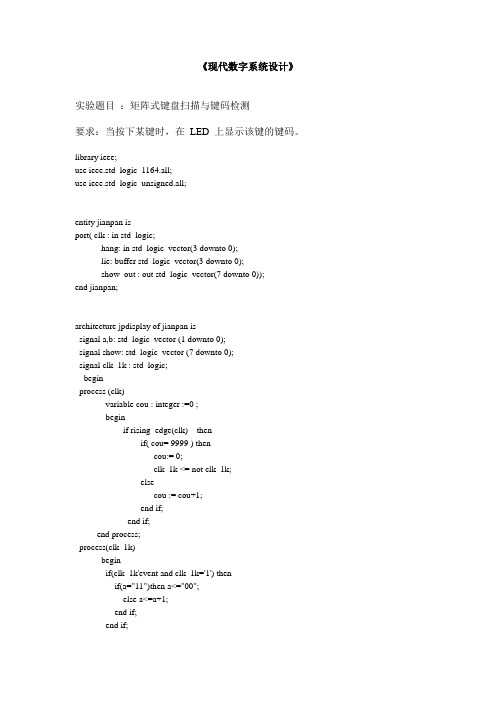
《现代数字系统设计》实验题目:矩阵式键盘扫描与键码检测要求:当按下某键时,在LED 上显示该键的键码。
library ieee;use ieee.std_logic_1164.all;use ieee.std_logic_unsigned.all;entity jianpan isport( clk : in std_logic;hang: in std_logic_vector(3 downto 0);lie: buffer std_logic_vector(3 downto 0);show_out : out std_logic_vector(7 downto 0));end jianpan;architecture jpdisplay of jianpan issignal a,b: std_logic_vector (1 downto 0);signal show: std_logic_vector (7 downto 0);signal clk_1k : std_logic;beginprocess (clk)variable cou : integer :=0 ;beginif rising_edge(clk) thenif( cou= 9999 ) thencou:= 0;clk_1k <= not clk_1k;elsecou := cou+1;end if;end if;end process;process(clk_1k)beginif(clk_1k'event and clk_1k='1') thenif(a="11")then a<="00";else a<=a+1;end if;end if;end process;process(clk_1k)begincase a iswhen "00"=>lie<="0001";b<="00";when "01"=>lie<="0010";b<="01";when "10"=>lie<="0100";b<="10";when "11"=>lie<="1000";b<="11";when others=>show<="00000000";end case;end process;process(clk_1k)begincase b iswhen "00" =>case hang iswhen "0001"=>show<="00111111"; --0when "0010"=>show<="00000110"; --1when "0100"=>show<="01011011"; --2when "1000"=>show<="01001111"; --3when others=>show<="00000000";end case;when "01" =>case hang iswhen "0001"=>show<="01100110"; --4when "0010"=>show<="01101101"; --5when "0100"=>show<="01111101"; --6when "1000"=>show<="00000111"; --7when others=>show<="00000000";end case;when "10" =>case hang iswhen "0001"=>show<="01111111"; --8when "0010"=>show<="01101111"; --9when "0100"=>show<="01110111"; --awhen "1000"=>show<="01111100"; --bwhen others=>show<="00000000";end case;when "11" =>case hang iswhen "0001"=>show<="00111001"; --cwhen "0010"=>show<="01011110"; --dwhen "0100"=>show<="01111001"; --ewhen "1000"=>show<="01110001"; --fwhen others=>show<="00000000";end case;when others=> show<="00000000";end case;show_out <= show;end process;end jpdisplay;。
键盘扫描

基于FPGA的键盘扫描电路一、设计目的:1.通过设计熟练掌握VHDL硬件描述语言在FPGA芯片上实现键盘接口设计;二、设计要求:1.键盘按钮数为4,系统时钟10MHz;2.能识别出所按按钮;3.按钮被按下后,视为此按钮输入一次,若按钮长时间不松,(时限1S)后每隔0.5S视为再次输入,直至按钮松开;4.要求能对按钮按下时指令的抖动能正确处理。
对持续时间小于50ms的输入不作响应;5.各键设置不同优先级,多键同时按下时,视为优先级较高的按键被按下;三、设计内容1.行列式键盘介绍1)行列式键盘概述为了减少键盘与单片机接口时所占用I/O口线的数目,在键数较多时,通常都将键盘排列成行列矩阵式,行列式键盘又叫矩阵式键盘。
用带有I/O口的线组成行列结构,按键设置在行列的交点上。
例如用2*2的行列结构可以构成4个键的键盘,4*4的行列结构可以构成有16个键的键盘。
这样,当按键数量平方增长时,I/O口线只是线性增长,这样就可以节省I/O口线。
2)行列式键盘原理行列式键盘的电路原理图如图3所示图3 行列式键盘电路原理图按键设置在行列线交叉点,行、列线分别连接到按键开关的两端。
列线通过上拉电阻接+5V的电压,即列线的输出被钳位到高电平状态。
行线与按键的一个引脚相连,列线与按键的另一个引脚相连。
判断键盘中有无按键按下是通过行线送入扫描信号,然后从列线读取状态得到的。
其方法是依次给行线送低电平,检查列线的输入。
如果列线信号全为高电平,则代表低电平信号所在的行中无按键按下;如果列线有输入为低电平,则低电平信号所在的行和出现低电平的列的交点处有按键按下。
设行扫描信号为keydrv3~keydrv0,列线按键输入信号keyin3~keyin0与按键位置的关系如表1所示。
表1 行扫描信号、列按键输入信号与按键位置的关系2 键盘电路与FPGA 接口实现1)系统结构和模块划分keydrv3~keydrv0keyin3~keyin0 对应的按键11101110 1 1101 2 1011 3 0111 41101 1110 5 1101 6 1011 7 0111 81011 1110 9 1101 0 1011 A 0111 B0111 1110 C 1101 D 1011 E 0111 F图4 键盘接口电路结构图由行列式键盘的原理可以知道,要正确地完成按键输入工作必须有按键扫描电路产生keydrv3~keydrv0信号。
键盘扫描及计算器VHDL仿真.docx
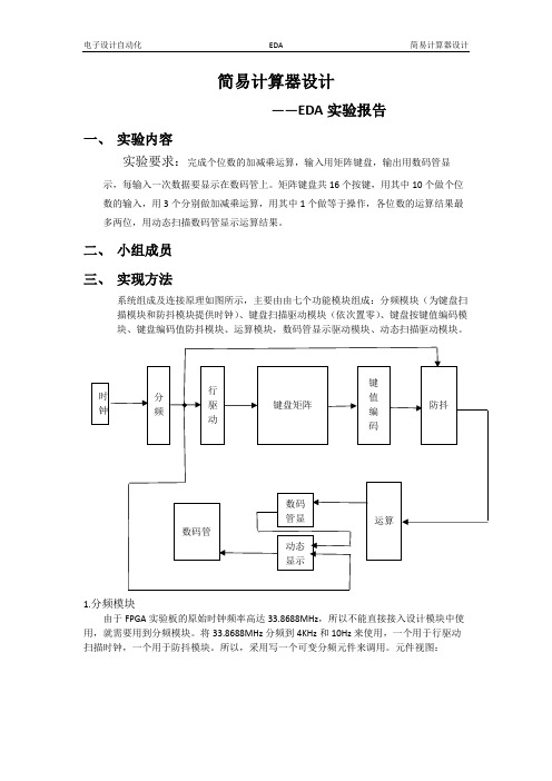
简易计算器设计——EDA实验报告一、实验内容实验要求:完成个位数的加减乘运算,输入用矩阵键盘,输出用数码管显示,每输入一次数据要显示在数码管上。
矩阵键盘共16个按键,用其中10个做个位数的输入,用3个分别做加减乘运算,用其中1个做等于操作,各位数的运算结果最多两位,用动态扫描数码管显示运算结果。
二、小组成员三、实现方法系统组成及连接原理如图所示,主要由由七个功能模块组成:分频模块(为键盘扫描模块和防抖模块提供时钟)、键盘扫描驱动模块(依次置零)、键盘按键值编码模块、键盘编码值防抖模块、运算模块,数码管显示驱动模块、动态扫描驱动模块。
1.分频模块由于FPGA实验板的原始时钟频率高达33.8688MHz,所以不能直接接入设计模块中使用,就需要用到分频模块。
将33.8688MHz分频到4KHz和10Hz来使用,一个用于行驱动扫描时钟,一个用于防抖模块。
所以,采用写一个可变分频元件来调用。
元件视图:主要代码如下(完整代码见附录,下同):architecture RTL of freq_division iscomponent fredivn isgeneric(n:positive);Port ( clkin:in STD_LOGIC;clkout:out STD_LOGIC);end component;beginU1:fredivngeneric map(n=>3)port map(clkin=>clk,clkout=>clkout_kb);end RTL;仿真结果如下图:达到预期的目的2.行驱动模块(依次对行置零):键盘扫描的原理就是检测行列信号然后判断出具体是按下了哪一个按键。
所以,对行依次置零,当置零频率较快时,按下某一个按键后,一定能得到某一列的信号输出为零,如下图:当行信号为1110时,若按下了0键,就会得到1110的列信号,立马就快可以译码出按键值,若按下4键、8键、C键则都不会有输出。
【例7-3】4x4键盘的VHDl扫描程序[2页]
![【例7-3】4x4键盘的VHDl扫描程序[2页]](https://img.taocdn.com/s3/m/0754ed03856a561253d36f58.png)
【例7-3】4X4键盘的VHDL扫描程序library ieee;use ieee.std_logic_1164.all;entity kbscan isport( clk :in std_logic;Kin :in std_logic_vector(3 downto 0);kout :out std_logic_vector(3 downto 0);result :out integer range 0 to 16);end kbscan;architecture bev of kbscan issignal scans :std_logic_vector(7 downto 0);signal scan: std_logic_vector(3 downto 0);signal I : integer range 0 to3;beginscans<=kin & scan;kout<=scan;process(clk) --进程,产生扫描信号beginif (clk'event and clk='1') thenif(i=3) theni<=0;else i<=i+1;end if;case i iswhen 0=> scan<=”1000”;when 1=> scan<=” 0100”;when 2=> scan<=” 0010”;when 3=> scan<=” 0001”;end case;end if;end process;process(clk) --进程,根据信号译码beginif (clk'event and clk='1') thenif(kin=”0000”) thenresult<=16;elsecase scans iswhen “00011000”=>result<=0;when “00101000”=>result<=1;when “01001000”=>r esult<=2;when “10001000”=>result<=3;when “00010100”=>result<=4;when “00100100”=>result<=5;when “01000100”=>result<=6;when “10000100”=>result<=7;when “00010010”=>result<=8;when “00100010”=>result<=9;when “01000010”=>result<=10;when “10000010”=>resu lt<=11;when “00010001”=>result<=12;when “00100001”=>result<=13;when “01000001”=>result<=14;when “10000001”=>result<=15;when others =>result<=16;end case;end if;end if ;end process;end bev;。
- 1、下载文档前请自行甄别文档内容的完整性,平台不提供额外的编辑、内容补充、找答案等附加服务。
- 2、"仅部分预览"的文档,不可在线预览部分如存在完整性等问题,可反馈申请退款(可完整预览的文档不适用该条件!)。
- 3、如文档侵犯您的权益,请联系客服反馈,我们会尽快为您处理(人工客服工作时间:9:00-18:30)。
library ieee;
use ieee.std_logic_1164.all;
use ieee.std_logic_unsigned.all;
entity jp is
port(
clk,start:in std_logic;
kbcol:in std_logic_vector(3 downto 0); --行扫描信号
kbrow:out std_logic_vector(3 downto 0); --列扫描信号
seg7_out:out std_logic_vector(6 downto 0);--显示控制信号
scan:out std_logic_vector(7 downto 0) --数码管地址选择控制信号
);
end jp;
architecture one of jp is
signal count,sta:std_logic_vector(1 downto 0);
signal seg7:std_logic_vector(6 downto 0);
signal dat:std_logic_vector(4 downto 0);
signal fn:std_logic; --按键标志位,判断是否有键被按下
begin
scan<="00000001"; --只使用一个数码管显示
--循环扫描计数器
process(clk)
begin
if clk'event and clk='1'then
count<=count+1;
end if;
end process;
--循环列扫描
process(clk)
begin
if clk'event and clk='1'then
case count is
when "00"=>
kbrow<="0001";
sta<="00";
when "01"=>
kbrow<="0010";
sta<="01";
when "10"=>
kbrow<="0100";
sta<="10";
when "11"=>
kbrow<="1000";
sta<="11";
when others=>
kbrow<="1111";
end case;
end if;
end process;
--行扫描译码
process(clk,start)
begin
if start='0'then
seg7<="0000000";
elsif clk'event and clk='1'then
case sta is
when "00"=>
case kbcol is
when "0001"=>
seg7<="1111001";
dat<="00011";
when "0010"=>
seg7<="1101101";
dat<="00010";
when "0100"=>
seg7<="0110000";
dat<="00001";
when "1000"=>
seg7<="1111110";
dat<="00000";
when others=>
seg7<="0000000";
dat<="11111";
end case;
when "01"=>
case kbcol is
when "0001"=>
seg7<="1111000";
dat<="00111";
when "0010"=>
seg7<="1011111";
dat<="00110";
when "0100"=>
seg7<="1011011";
dat<="00101";
when "1000"=>
seg7<="0110011";
dat<="00100";
when others=>
seg7<="0000000";
dat<="11111";
end case;
when "10"=>
case kbcol is
when "0001"=>
seg7<="0011111";
dat<="01011";
when "0010"=>
seg7<="1110111";
dat<="01010";
when "0100"=>
seg7<="1111011";
dat<="01001";
when "1000"=>
seg7<="1111111";
dat<="01000";
when others=>
seg7<="0000000";
dat<="11111";
end case;
when "11"=>
case kbcol is
when "0001"=>
seg7<="1000111";
dat<="01111";
when "0010"=>
seg7<="1001111";
dat<="01110";
when "0100"=>
seg7<="0111101";
dat<="01101";
when "1000"=>
seg7<="1001110";
dat<="01100";
when others=>
seg7<="0000000";
dat<="11111";
end case;
when others=>
seg7<="0000000";
end case;
end if;
end process;
--产生按键标志位,用于存储按键信息
fn<=not (dat(0) and dat(1) and dat(2) and dat(3) and dat(4));
process(fn)
begin
if fn'event and fn='1'then --按键信息存储
seg7_out <=seg7;
end if;
end process;
end one;。
