50.34-698自动化系统
自动化系统报价单

自动化系统报价单一、引言自动化系统是现代工业中不可或缺的重要组成部分,它能够提高生产效率、降低人力成本、提升产品质量等。
本报价单旨在为您提供一份详细的自动化系统报价,以满足您的需求。
二、系统概述本自动化系统报价单所涵盖的是一个针对生产线的自动化控制系统。
该系统包括以下主要组成部分:1. 控制器:采用先进的PLC(可编程逻辑控制器)控制器,具有高性能和稳定性,能够实时监测和控制生产线的各个环节。
2. 传感器:配备多种传感器,如温度传感器、压力传感器、光电传感器等,用于实时采集各种参数数据,并反馈给控制器进行处理。
3. 执行器:包括电动执行器、气动执行器等,用于根据控制器的指令执行相应的动作,实现自动化控制。
4. 人机界面:采用触摸屏或工业级显示器,提供直观的操作界面,方便操作人员进行监控和控制。
5. 通信模块:用于与上位机或其他设备进行数据交互,实现远程监控和控制。
三、详细报价以下是本报价单中各个组成部分的详细报价:1. 控制器:PLC控制器型号XYZ-1000,单价1000美元,数量:1台,总价:1000美元。
2. 传感器:温度传感器型号ABC-200,单价50美元,数量:10个,总价:500美元;压力传感器型号DEF-300,单价80美元,数量:5个,总价:400美元;光电传感器型号GHI-400,单价60美元,数量:8个,总价:480美元。
总价:1380美元。
3. 执行器:电动执行器型号JKL-500,单价200美元,数量:2个,总价:400美元;气动执行器型号MNO-600,单价150美元,数量:3个,总价:450美元。
总价:850美元。
4. 人机界面:触摸屏型号PQR-700,单价300美元,数量:1个,总价:300美元;工业级显示器型号STU-800,单价250美元,数量:2个,总价:500美元。
总价:800美元。
5. 通信模块:通信模块型号VWX-900,单价150美元,数量:1个,总价:150美元。
通信建设工程预算定额第三册无线通信设备安装工程

通信建设工程预算定额第三册无线通信设备安装工程中华人民共和国工业和信息化部二00八年五月工业和信息化部文献工信部规[2023]75号有关公布《通信建设工程概算预算编制措施》及有关定额旳告知各省、自治区、直辖市通信管理局,中国电信集团企业、中国网络通信集团企业、中国移动通信集团企业、中国联合通信有限企业、中国卫星通信集团企业、中国铁通集团有限企业:为适应通信建设发展需要,合理和有效控制工程建设投资,规范通信建设概算、预算旳编制与管理,根据国家法律、法规及有关规定,我部修订了《通信建设工程概算、预算编制措施及费用定额》(邮部【1995】626号)以及通信建设工程预算定额等原则。
新修订旳通信建设工程概算、预算定额配套文献包括:《通信建设工程概算、预算编制措施》,《通信建设工程费用定额》,《通信建设工程施工机械、仪器仪表台班定额》,《通信建设工程预算定额》(共五册:第一册通信电源设备安装工程、第二册有线通信设备安装工程、第三册无线通信设备安装工程、第四册通信线路工程、第五册通信管道工程)。
现予公布,自2008年7月1日起实行。
自实行之日起原邮电部《有关公布<通信建设工程概算、预算编制措施及费用定额>等原则旳告知》(邮部【1995】626号)以及《有关公布<通信建设工程施工机械台班费用定额>等2项定额原则旳告知》(邮部【1996】528号)同步废止。
附件:1.通信建设工程概算、预算编制措施2.通信建设工程费用定额3.通信建设工程施工机械、仪器仪表台班定额4.通信建设工程预算定额中华人民共和国工业和信息化部(章)二00八年五月二十四日(附件另发)主题词:邮电通信建设预算告知抄送:国家发展和改革委员会,财政部,住房和城镇建设部。
工业和信息化部办公厅2008年5月27日印发总说明一、通信建设工程预算定额(如下简称本定额)系通信行业原则。
二、本定额按通信专业工程分册,包括:第一册通信电源设备安装工程(册名代号TSD)第二册有线通信设备安装工程(册名代号TSY)第三册无线通信设备安装工程(册名代号TSW)第四册通信线路工程(册名代号TXL)第五册通信管道工程(册名代号TGD)三、本定额是编制通信建设项目投资估算、概算、预算和工程量清单旳基础。
和谐XPS安全自动化产品数据表说明书

Product data sheetSpecificationsTime delayed output, Harmony XPS,for Estop, guard, OSSD, 24 V AC/DC, springXPSBAT12A1ACMainRange of ProductHarmony Safety Automation Product or Component Type Safety module Safety module name XPSBATSafety module application For emergency stop and protective guard applications For OSSD monitoringFunction of moduleEmergency stop button with 2 NC contacts Guard monitoring with 1 or 2 limit switches Light curtain monitoring RFID switchMonitoring of electro-sensitive protection equipment (ESPE)Safety levelCan reach PL e/category 4 for normally open relay contact ISO 13849-1Can reach SILCL 3 for normally open relay contact IEC 62061Can reach SIL 3 for normally open relay contact IEC 61508Can reach PL c/category 1 for normally closed relay contact ISO 13849-1Can reach SILCL 1 for normally closed relay contact IEC 62061Can reach SIL 1 for normally closed relay contact IEC 61508Safety reliability dataMTTFd > 30 years ISO 13849-1Dcavg >= 99 % ISO 13849-1PFHd = 0.98E-09 for SS0 ISO 13849-1PFHd = 0.96E-09 for SS1 ISO 13849-1HFT = 1 IEC 62061PFHd = 0.98E-09 for SS0 IEC 62061PFHd = 0.96E-09 for SS1 IEC 62061SFF > 99% IEC 62061HFT = 1 IEC 61508-1PFHd = 0.98E-09 for SS0 IEC 61508-1PFHd = 0.96E-09 for SS1 IEC 61508-1SFF > 99% IEC 61508-1Type = B IEC 61508-1Electrical circuit type NC pair OSSD pairConnections - terminalsRemovable spring terminal block, 0.2...2.5 mm² solid or flexibleRemovable spring terminal block, 0.25...2.5 mm² flexible with ferrule single conductor Removable spring terminal block, 0.2...1.5 mm² solid or flexible twin conductorRemovable spring terminal block, 2 x 0.25...1 mm² flexible with ferrule without cable end, with bezel Removable spring terminal block, 2 x 0.5...1.5 mm² flexible with ferrule with cable end, with bezel [Us] Rated Supply Voltage24 V AC - 15...10 %24 V DC - 20...20 %ComplementarySynchronisation time between inputs 0.5 s 2 sType of startAutomatic/manual/monitored Power consumption in W2 W 24 V DCD i s c l a i m e r : T h i s d o c u m e n t a t i o n i s n o t i n t e n d e d a s a s u b s t i t u t e f o r a n d i s n o t t o b e u s e d f o r d e t e r m i n i n g s u i t a b i l i t y o r r e l i a b i l i t y o f t h e s e p r o d u c t s f o r s p e c i f i c u s e r a p p l i c a t i o n sPower consumption in VA5 VA 24 V AC 50/60 HzInput protection type Internal, electronicSafety outputs 2 NO1 NOSafety inputs2Maximum wire resistance500 OhmTime delay range0...900 sInput compatibility Normally closed circuit ISO 14119Mechanical contact ISO 14119OSSD pair IEC 61496-1-2Normally closed circuit ISO 138503-wire proximity sensors PNP[Ie] rated operational current5 A AC-13 A AC-155 A DC-13 A DC-13Control outputs 3 pulsed outputInput/Output type Semiconductor output Z1, 20 mA[Ith] conventional free air12 Athermal currentAssociated fuse rating6 A gG NO relay output circuit IEC 60947-1 Minimum output current20 mA relay outputMinimum output voltage24 V relay outputMaximum response time on20 msinput open[Ui] rated insulation voltage250 V 2)EN/IEC 60947-1[Uimp] rated impulse withstand4 kV II EN/IEC 60947-1voltageLocal signalling LED green power power ONLED red error errorLED yellow state 1 safety output instantaneousLED yellow state 2 safety output delayedLED yellow start 1 startLED yellow start 2 startLED yellow S12 safety input S12LED yellow S22 safety input S22Mounting Support35 mm symmetrical DIN railDepth 4.72 in (120 mm)Height 3.94 in (100 mm)Width 1.77 in (45 mm)Net Weight0.77 lb(US) (0.350 kg)EnvironmentStandards IEC 60947-5-1IEC 61508-1 functional safety standardIEC 61508-2 functional safety standardIEC 61508-3 functional safety standardIEC 61508-4 functional safety standardIEC 61508-5 functional safety standardIEC 61508-6 functional safety standardIEC 61508-7 functional safety standardISO 13849-1 functional safety standardIEC 62061 functional safety standardProduct certifications TÜVcULusIP degree of protection IP20 terminals)EN/IEC 60529IP40 housing)EN/IEC 60529IP54 mounting area)EN/IEC 60529 Ambient air temperature for-13…131 °F (-25…55 °C)operationAmbient Air Temperature for-13…185 °F (-25…85 °C)StorageRelative Humidity5…95 % non-condensingOrdering and shipping detailsCategory22477-SAFETY MODULES (PREVENTA)Discount Schedule SAF2GTIN3606482034037Nbr. of units in pkg.1Package weight(Lbs)10.65 oz (302 g)Returnability NoPacking UnitsUnit Type of Package 1PCEPackage 1 Height 2.52 in (6.4 cm)Package 1 width 5.24 in (13.3 cm)Package 1 Length 6.02 in (15.3 cm)Unit Type of Package 2S03Number of Units in Package 216Package 2 Weight11.92 lb(US) (5.409 kg)Package 2 Height11.81 in (30 cm)Package 2 width11.81 in (30 cm)Package 2 Length15.75 in (40 cm)Package 3 Height11.81 in (30 cm)Offer SustainabilitySustainable offer status Green Premium productCalifornia proposition 65WARNING: This product can expose you to chemicals including: Lead and lead compounds, which isknown to the State of California to cause cancer and birth defects or other reproductive harm. For moreinformation go to REACh Regulation REACh DeclarationEU RoHS Directive Pro-active compliance (Product out of EU RoHS legal scope)EU RoHS DeclarationMercury free YesRoHS exemption information YesChina RoHS Regulation China RoHS declarationEnvironmental Disclosure Product Environmental ProfileCircularity Profile End of Life InformationWEEE The product must be disposed on European Union markets following specific waste collection andnever end up in rubbish bins.Dimensions Drawings DimensionsFront and Side Views(A) : Product drawing(B) : Spring terminal(C) : Side view(1) : Removable terminal blocks, top(2) : Removable terminal blocks, bottom(3) : LED indicators(4) : Delay factor selector(5) : Delay base selector(6) : Sealable transparent coverMounting to DIN railScrew-mountingConnections and SchemaWiring Diagram(1) : A1-A2 (Power supply)(2) : S11–S21 (Control outputs (DC+) of safety-related inputs), S12-S22 (Input channels (CH+) of safety-related inputs)(3) : Y1 (Control output of Start/Restart input), Y2 (Input channel for automatic/manual start), Y3 (Input channel for monitored start with falling edge)13-14-23-24 : Terminals of the safety-related outputs (instantaneous)37-38 : Terminals of the safety-related outputs (delayed)Z1 : Solid state output, not safety-related。
BF6910(BF6911)ASXX规格书
3.1 引脚图 ....................................................................................................................................................... 6 3.2 引脚描述 ................................................................................................................................................... 6
系统性能偏差表
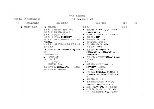
系统技术性能偏差表投标方名称:威胜集团有限公司日期:2014年11月20日序号系统或设备名称招标文件要求投标书指标偏差说明1 费控智能电能表 3.1规格要求单相表:准确度等级:有功2.0级;三相表:准确度等级:有功1级;单相表:参比电压:220V;三相表:参比电压:3³220/380V;参比电流:电能表采用直接接入方式,规格为5(60)A。
脉冲常数:电能表的脉冲常数由下式决定并取百位整数:C= (2~3)³107/(m²Un²Imax²t)imp/kWh,式中:C——电能表常数;m——测量单元数;Un——参比电压;Imax——最大电流;t——时间间隔,为1h。
电表脉冲常数:1200 imp/kWh。
三相表:统一按照国网公司标准设置。
单相表:●电流规格:1.5(6)A、5(30)A、5(40)A、5(60)A、10(40)A、●10(60)A、10(100)A、20(80)A●参比电压:220V●参比频率:(50±2.5)Hz●准确度等级:有功2级●静态功耗:≤1.5W、10V A●设计寿命:≥15年●脉冲常数:6400imp/kW²h、3200imp/kW²h、1600imp/kW²h、800imp/kW²h●外型尺寸:长³宽³厚=160mm³112mm³71mm三相表:●参比电压:3³57.7V/100V,3³220V/380V(三相四线)●3³100V(三相三线)●标定电流:3³1.5(6)A、3³5(20)A、3³10(40)A、3³15(60)A、3³10(100)A等●频率范围:50±2.5Hz;●电压测量范围及误差:PT供电时:70%Un~130% Un,偏差≤0.5%●功耗:<1.5W,6V A(每一电压线路)●时钟误差:≤0.5 s/d ((在-40℃~+85℃的温度范围内±3.5ppm的晶振))无偏差●内部电池寿命:≥10年●设计寿命:≥1.5³105 h ●MTBF:60000h●冲击电压:6kV●交流电压:4kV●快速瞬变脉冲群:4kV2 费控智能电能表 3.2机械性能要求电能表的机械和结构要求除应符合国家电网公司《单相智能电能表型式规范》的规定外,还应满足下述条款的要求。
DLT698(可编辑)
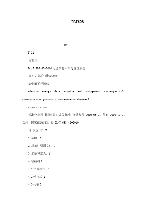
DLT698ICS:F 21备案号:DL/T 698.42-2010电能信息采集与管理系统第4-2 部分通信协议-集中器下行通信electro energy data acquire and management systempart4-2: communication protocol- concentrator downwardcommunication标准分享网提示:非正式版标准仅供参考2010-05-01 发布 2010-10-01 实施国家能源局发布 DL/T 698.42-2010目次前言 II1 范围. 12 规范性引用文件 13 术语和定义. 14 帧结构14.1字节格式. 14.2帧格式 14.3传输35 数据标识 35.1数据标识结构 35.2数据传输形式 56 应用层56.1读数据 56.2读通信地址66.3写数据 66.4广播校时. 76.5写通信地址76.6更改通信速率 76.7修改密码. 86.8最大需量清零 8附录 A 规范性附录数据标识编码表. 10附录 B 规范性附录预付费数据结构23附录 C(规范性附录)状态字、特征字和错误信息字 24附录 D(资料性附录)帧校验序列(FCS)算法. 25I标准分享网 //0>. 免费下载DL/T698.42-2010前言DL/T 698《电能信息采集与管理系统》是对 DL/T 698-1999《低压电力用户集中抄表系统技术条件》的修订,DL/T698 由下列部分组成:DL/T 698.1-2009 电能信息采集与管理系统第 1部分总则;DL/T 698.2-2010 电能信息采集与管理系统第 2部分主站技术规范;DL/T 698.31-2010 电能信息采集与管理系统第 3-1 部分电能信息采集终端技术规范-通用要求;DL/T 698.32-2010 电能信息采集与管理系统第 3-2 部分电能信息采集终端技术规范-厂站采集终端特殊要求;DL/T 698.33-2010 电能信息采集与管理系统第 3-3 部分电能信息采集终端技术规范-专变采集终端特殊要求;DL/T 698.34-2010电能信息采集与管理系统第 3-4部分电能信息采集终端技术规-公变采集终端特殊要求;DL/T 698.35-2010 电能信息采集与管理系统第 3-5 部分电能信息采集终端技术规范-低压集中抄表终端特殊要求;DL/T 698.41-2010 电能信息采集与管理系统第 4-1 部分通信协议-主站与电能采集终端通信;DL/T 698.42-2010 电能信息采集与管理系统第 4-2 部分通信协议-集中器下行通信。
提取车间自动化系统URS

提取车间自动化系统用户需求说明目录1.介绍 (3)2. 目的 (3)3.范围 (3)3.1系统范围 (3)3.2工程内容和施工范围 (3)4.职责 (4)4.1系统使用部门 (4)4.2设备工程部 (4)4.3质量管理部 (4)5. 缩略语 (4)6. 法规和指南 (6)1.1法规 (6)2.2 指南 (6)7.公用系统参数需求 (7)8.用户需求 (8)9.推荐供应商品牌 (31)10. 附件错误!未定义书签。
1.介绍本用户需求说明(URS)是为了规定****制药有限公司提取车间自动化控制系统工程的技术要求,为该系统的招标提供技术依据,并作为后续验证工作的基础,包括:FAT草案和报告、DQ草案和报告、SAT草案和报告、IQ草案和报告、OQ草案和报告、PQ草案和报告。
本文件作为供应商编制设备设计制造、调试和服务技术条款的基础,供应商应根据本文件需求逐条做出响应,提供其技术要求是否满足本文件需求标准,如有偏差和不符合项应列出,并详细说明或提供解决方案。
在本URS中用户仅提出基本的技术要求和设备的基本要求,并未涵盖和限制卖方设备具有更高的设计与制造标准和更加完善的功能、更完善的配置和性能、更优异的部件和更高水平的控制系统。
卖方应在满足本URS的前提下提供卖方能够达到的更高标准和功能的高质量设备及其相关服务。
卖方的设备应满足中国有关设计、制造、安全、环保等规程、规范和强制性标准要求。
如遇与卖方所执行的标准发生矛盾时,应按较高标准执行(强制性标准除外)。
2.目的用户需求说明是系列技术说明中的第一个。
它是用户对项目范围的预期情况进行的高层次说明,是用户对提取车间自动化控制系统工程的技术要求的详述,是设计的依据,决定了中药产业化项目取车间自动化控制系统的性能,同时为中药产业化项目取车间自动化控制系统设计、测试、验证提供了可接受标准依据。
3.范围3.1系统范围系统描述:本系统包括取车间自动化控制系统及其附属仪表、阀门等设施等所有必要的附件。
Agilent Bravo 自动化液体处理平台配件选择指南说明书

Accessories for the Agilent Bravo Automated Liquid Handling PlatformSelection GuideIntroductionThe Agilent Bravo Automated Liquid Handling Platform provides unparalleledversatility and precision in a compact footprint. With proven high-accuracy pipette heads and a flexible nine-position open deck, it offers the flexibility needed to scale-up applications ranging from serial dilutions to PCR and cell-based assays. A carefully designed group of accessories is at the heart of the Bravo’s flexibility, providing the range of tools needed by scientists and engineers to reduce manual intervention and increase throughput and walkway time when automating routine and customized applications. Bravo accessories make it possible to configure any of the nine available deck positions for shaking, heating, cooling, filtration, and more.The Bravo Automated Liquid Handling Platform is compatible with the following: • Agilent designed and tested accessories• Proven, industry standard accessories customized for use with the Bravo platform • User accessories that fit with the Bravo platform open architectureFigure 1. The Bravo Platform 9-position deck accommodates accessories designed to facilitate applications. The labeled deck image includes a Bravo accessories configuration designed for Next Generation Sequencing sample preparation.Example of a Bravo deck layout Components1. Available for an accessory2. Available for an accessory3. Available for an accessory4. Peltier Thermal Station with Custom Plate Nest5. Orbital Shaking Station6. Peltier Thermal Station with Custom Plate Nest7. Magnetic Bead Accessory 8. Available for an accessory 9. Thermal Station1472583691 - Agilent VWorks Automation Control Software.2 - Agilent Bravo Platform accessories may contain 3rd-party components which have been customized and optimized for use with the Bravo Platform, and which are supported by Agilent.3 - NA = Not applicable.For Research Use Only. Not for use in diagnostic procedures. This information is subject to change without notice.©Agilent Technologies, Inc., 2012Published in the USA, April 12, 20125991-0126ENApplications Enabled by Bravo AccessoriesBravo Platform accessories are carefully designed tools that deliver the flexibility and versatility you need to automate a wide range of key applications. The table below shows a selection of applications that are enabled using BravoPlatform accessories. For complete configurations tailored to yourapplication, contact Agilent.Agilent Bravo Platform ConsumablesA complete range of pipette tips is also available for use with Bravo Platform accessories. Visit /lifesciences/pipettetips for more information.Learn More/lifescience/automationFind a local Agilent customer center /chem/contactus USA and Canada 1-800-227-9770*****************************Europe************************Asia Pacific************************。
【微计算机信息】_工业控制软件_期刊发文热词逐年推荐_20140725

通用型 通信板卡 逆变器 运动控制 迁移映射 输出 软启动 软件重用 软件路由模拟 软件设计 软件模拟 软plc 超越函数e-τ s 超声波测距 调频连续波雷达测距 试验环道 设计模式 设备驱动 计算机系统 视频监控 规则采样法 衰减系数 蚁群优化算法 虚拟驾驶员 虚拟仪器 蓝牙技术 芯体卷绕 脉冲量 网际组态软件webaccess 网络路由 网络控制 网络 网卡 组态王6.5 组态王6.1 组态 红外探测 系统软件 系统测评 粒子群算法 管控一体 等效面积法 移相触发 磨矿分级流程 硬件设计 硬件组态 短时交通流 监测控制 监控 电路 电池 电机 电力信息 用户模式
推荐指数 5 5 4 4 4 4 3 3 3 3 3 3 3 2 2 2 2 2 2 2 2 2 2 2 2 2 2 2 2 2 2 2 2 2 2 2 2 2 2 2 2 2 1 1 1 1 1 1 1 1 1 1
2009年 序号 1 2 3 4 5 6 7 8 9 10 11 12 13 14 15 16 17 18 19 20 21 22 23 24 25 26 27 28 29 30 31 32 33 34 35 36 37 38 39 40 41 42 43 44 45 46 47 48 49 50 51 52
科研热词 控制系统 plc 嵌入式 opc 单片机 labview dsp 自动化 胶印机 组态软件 监控 数据采集 工业控制 工业以太网 嵌入式系统 实时监控 天线通信 墨斗操作台 协议 profibus-dp opc服务器 lf2407 led ifix fpga can总线 集散控制系统 集成驱动控制器 防抖系统 长距输送 锌空电池 远程控制 运动关节 软件项目 软件平台 软plc 车身网络 踝关节康复并联机器人 路灯监控 跟踪控制 超文本传输协议 超临界萃取 调速控制 试验机控制系统 译码 计算机 视频监控 行为特征 虚拟化 虚拟仪器技术 节能 自整定
3 ABB选型价格查询手册 转换开关 低压产品
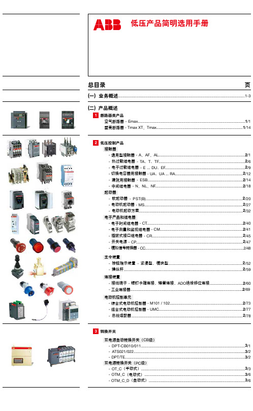
1 断路器类产品 空气断路器 - Emax...................................................................................................1/1 塑壳断路器 - Tmax XT、Tmax................................................................................1/14
连接装置 - 接线端子 - 螺钉卡箍连接、弹簧连接、ADO绝缘移位连接...............................2/60 - 工业连接器........................................................................................................2/69
双电源转换开关(PC级) - OT_C(手动式)................................................................................................3/3 - OTM_C(电动式).............................................................................................3/6 - OTM_C_D(自动式).........................................................................................3/6
安装说明-Compact 5000 I O 数字量 8 点安全拉出型输入模块说明书
安装说明Compact 5000 I/O 数字量 8 点安全拉出型输入模块目录号 5069-OBV8S 、5069-OBV8SKThe 5069-OBV8S 和 5069-OBV8SK 模块是 8 点安全拉出型输入模块。
这些模块在安全控制网络上提供满足以下要求的安全 I/O ,该等要求包括 SIL CL3 和 PLe, Cat. 4,如 IEC 61508、IEC 61511、IEC 62061 和 ISO 13849-1 中所规定。
该模块提供拉出型输出和双极性类型输出。
您可将 Compact 5000™ I/O 安全模块用作带 CompactGuardLogix®5380 控制器的本地和远程 I/O 模块,以及带 Compact GuardLogix 5380 和 GuardLogix 5580 控制器的远程 I/O 模块。
5069-IB8SK 模块提供与 5069-IB8S 模块相同的功能,但具有保形涂层,有助于在恶劣环境中提供保护。
使用 Studio 5000 Logix Designer® 软件配置模块。
Compact GuardLogix 5380 和 GuardLogix 5580 控制器必须使用 32.011 或更高的固件版本,才可使用 Compact 5000 I/O 安全模块。
Compact 5000 I/O 安全模块采用生产者/消费者通信模式。
生产者/消费者通信模式是模块与其他系统设备之间的一种智能数据交换,在通信过程中,每个模块都会生成数据,而不是先被轮询。
有关如何使用 Compact 5000 I/O 模块的更多信息,请参见第12页的其他资源中列出的出版物。
变更摘要主题页码关于模块5安装系统5安装可拆卸端子块7安装模块8安装终端盖9对可拆卸端子块进行接线9断开电线与可拆卸端子块之间的连接9使用束线带10为系统供电10拆卸模块10技术参数11其他资源12主题页码删除接线图有关如何连接模块的信息,请参阅中第12页的其他资源列出的出版物不适用Compact 5000 I/O 数字量 8 点安全拉出型输入模块ATTENTION:Read this document and the documents listed in the Additional Resources section about installation, configuration and operation of this equipment before you install, configure, operate ormaintain this product. Users are required to familiarize themselves with installation and wiring instructions in addition to requirements of all applicable codes, laws, and standards.Activities including installation, adjustments, putting into service, use, assembly, disassembly, and maintenance are required to be carried out by suitably trained personnel in accordance with applicable code of practice.If this equipment is used in a manner not specified by the manufacturer, the protection provided by the equipment may be impaired.注意:在安装、配置、操作和维护本产品前,请阅读本文档以及“其他资源”部分列出的有关设备安装、配置和操作的相应文档。
河北隶能电气产品选型手册2019-1

系列号
型号
保护功能
备注
LN-9100 变电站 综合自 动化系
统
LN-9185 微机变压器差 动保护测控装
置
LN-9175 微机变压器后 备保护测控装
置
LN-9176 微机变压器保 护测控装置
LN-9116 微机线路保护
测控装置
差速断保护,比率制动及谐波制动
的差动保护,重瓦斯,有载重瓦斯,
轻瓦斯,有载轻瓦斯,油温,压力
ห้องสมุดไป่ตู้ 系统构成
变电站层:包括当地监控系统和通讯管理系统,全面提供设备状态监视与控 制、保护信息记录与分析,通讯管理系统将采集信息经灵活处理后及时准确的上 传至调度所;间隔层:包括按间隔分布式配置的保护、测控和自动控制装置。间 隔层设备根据需要可集中组屏或直接下放至开关柜,各间隔层设备相对独立,仅 通过现场总线 CAN 网互联,并同变电站层的通讯管理机通信。
LN-8000 系列微机小电流系统接地选线装置是我公司最新研制的新型小电 流系统接地选线装置,它适用于中性点不接地或经消弧线圈、电阻接地的运行方 式系统,能够迅速准确地查找出系统单相接地线路。该装置以 32 位微处理器为 核心,配以液晶显示器、信号灯指示、轻触式按键。具有操作简单,选线准确, 速度更快、运行可靠等特点。
零序过压,负序过流保护,低电压
护测控
保护,非电量保护等功能
发电厂 保护系
统
LN-9146 微机备用电源 自投保护测控
装置
LN-9169 微机母线绝缘
监察装置 LN-9165 微机公用测控
装置 LN-9187 微机发电机差 动保护装置 LN-9177 微机发电机后 备保护装置 LN-9178 微机发电机后 备保护装置 LN-9193 励磁电压调整
柳林 MGTR-W4131 微功耗遥测终端使用说明书

MGTR-W4131微功耗遥测终端产品使用手册智能传感终端系列版本:1.0.0日期:2022-4-11状态:临时文件市柳林自动化设备有唐山市柳林自动化设备有限公司市柳林自动化设备有限公司前言唐山市柳林自动化设备有限公司是一家专业从事物联网安全通讯终端、智能仪表与智慧应用系统的研发、生产、销售和系统工程技术服务的高新技术企业,河北省双软企业。
公司成立于2007年,拥有1总部(唐山)提供物联网智能终端、数字孪生、SaaS、PaaS、DaaS的研发、生产及销售;1中心(合肥)负责工程系统运维及客户服务,倾听需求,解决问题,成就客户;1研究院(南京)提供生态系统服务10+优质生态合作伙伴、100+核心渠道伙伴、20万+已实施系统现场软硬件设备在线运行。
如您需要任何帮助,您可以关注“唐山柳林自动化”公众号了解产品信息,也可以随时联系我司唐山总部,联系方式如下:地址:河北唐山高新区火炬路410号110楼3号客服热线:130****1802(24小时在线)邮箱:*********************网址:https://免责声明由于产品版本升级或其他原因,本文档内容会不定期更新。
除非另有约定,本文档仅作为使用指导,本文档中的所述内容、信息和建议均不构成任何明示或暗示的担保。
设备正常操作及安装对于测量的精度以及可靠性影响很大,因此必须保证安装的正常性,并进行反复检查。
保密义务除非唐山市柳林自动化设备有限公司特别授权,否则我司所提供文档和信息的接收方须对接收的文档和信息保密,不得将其用于除本项目的实施与开展以外的任何其他目的。
未经我司书面同意,不得获取、使用或向第三方泄露我司所提供的文档和信息。
对于任何违反保密义务、未经授权使用或以其他非法形式恶意使用所述文档信息或图片的违法侵权行为,我司有权追究法律责任。
版权申明本文档版权属于唐山市柳林自动化设备有限公司,任何人未经我司允许而复制转载该文档将承担法律责任。
版权所有©唐山市柳林自动化设备有限公司2022,保留一切权利。
Agilent 34980A多功能开关 测量单元数据手册说明书

Agilent 34980AMultifunction Switch/Measure Unit Data Sheet•8-slot mainframe with 19 mix-and-match plug-in modules so you can create your own custom configuration •High-performance switching:Up to 560 2-wire multiplexer channels or 1024 matrix cross-points in one mainframe •Optional built-in 6 12-digit DMM lets you make 11 measurements with over 3000 readings/sec •Easy to integrate: Built-in Ethernet, USB 2.0, and GPIB connectivity, standard connectors and software drivers for most common programming environmentsC O N F I G U R E,C O N N E C T,G OIf you use automated test equipment for design validation or manufacturing,you now have a cost-effectivealternative to PXI and VXI test-system platforms. The 34980A multifunction switch/measure unit provides compa-rable functionality that is much easier to use than PXI and VXI and costs less.The 34980A helps you lower your cost of test and accelerate your test-system integration and development.The 34980A handles your system switching needs up to 20 GHz and provides basic measurements and system control. It offers optional DMM measurements, counter/totalizerfunctionality, digital I/O with pattern capabilities, and analog outputs with basic waveforms—all in one low-cost,compact box. And with its standard connectors and software drivers,computer-standard I/O, and Web browser interface, the 34980A easily integrates into electronic functional test and data acquisition systems.Flexible switching, measure-ments, and system controlThe 34980A accommodates up to 8 plug-in modules to give you the flexibility you need. Choose from 19different modules to define your own configuration. You can buy what you need now and add to it or reconfigure it as your requirements change. Whether you are measuring tempera-ture, AC or DC voltage, resistance,frequency, current, or custom mea-surements, the 34980A offers thefunctionality you need in a single box.Switch in different measurements with high-performance signal switching—no external signal conditioning is required. Choose between different switch types and topologies with frequency ranges from DC to 20 GHz.The 34980A offers high-density multiplexers for scanning multiple channels, matrices for connecting multiple points at one time, and general purpose switches for simple control and high power e the 34980A to route individual signals or monitor multiple signals over a specified period of time—monitor a single channel or multiple channels, set alarms, and identify irregularities.The 34980A also offers flexible choices for system control. You can control external devices such as microwave switches, attenuators, solenoids, and power relays. Or use the digital inputs to sense limit-switch and digital-bus status.Optimized for test systemsThe 34980A has the performance you need for medium- to high-density switching/measurement applications such as design verification, functional test and data acquisition. Your signals are switched to the right measurement device without compromising signal integrity. Switch your signals to the optional internal DMM and achieve optimal throughput on switch closure time. Or, if you prefer, you can easily connect to external instruments such as DMMs, scopes, power supplies,and more. What’s more, with the built-in Ethernet interface, you can control the 34980A and collect data from remote locations.The rugged instrument comes with a variety of system-ready features:•Web browser interface shows settings at a glance and provides remote access and control •Self-guiding front panel to configure,troubleshoot or view data •Low EMI and efficient system cooling•Heavy-duty cabling and connection options•Rack mount options•Relay counters help predict end-of-life•In-rack calibration for reduced maintenance time•DMM measurement accuracies include the switch for simple calculations2High-performance unit provides low-cost alternative to PXI and VXI switch and measurement platformsMake system connections easilyand quickly with simple, reliable connection options:•Built-in Ethernet, USB 2.0, and GPIB connectivity•Standard IVI and LabVIEW software drivers•Low-cost, standard 50- or 78-pin Dsub connectors and cables •Detachable terminal blocks with strain relief•Mass interconnect solutions In addition, the 34980A comes with Agilent E2094N IO Libraries Suite 14.0. Quickly establish an error-free connection between your PC and instruments—regardless of vendor.The IO Libraries provide robustinstrument control and work with the software development environment you choose.Easier signal routing with four2-wire internal analog buses. You can route your measurements directly to the internal DMM, or you can connect to external instruments through the analog bus connector on the rear of the mainframe. And since you have four 2-wire buses, you can dedicate one bus for use with the internal DMM and use the other three buses for module extensions or additional signal routing between modules,reducing your wiring needs.You can define switch sequences to control complex signal routing and the order of switch closures. Assign a sequence, give it a name and then execute it with the name you created. External trigger capabilities make it easy for you to time and synchronize measurements and other events. This can help you determine when to begin or end an acquisition.Measurements you can trustGet proven performance from Agilent instruments, with the resolution,repeatability, speed, and accuracy you’ve come to expect.The 34980A offers built-in signal conditioning and modular flexibility.When you use it with the internalDMM, you can configure each channel independently for the measurements you choose. It includes a variety of features that give you confidence in your measurements:•61⁄2digits of resolution with .004% of accuracy with DC voltage measurements•Alarms per channel—high limit, low limit, or both•Math functions—use Mx+B for custom linear conversions and converting raw inputs•Built-in thermocouple reference for temperature measurements (34921T)•Time-stamped readingsThe integrated DMM is mounted inside the mainframe and does not consume any of the eight user-available slots. You can access the DMM through any switch module that connects to the analog bus, or directly from the analog bus connector on the rear of the mainframe. The internal DMM gives you the flexibility to measure 11 types of inputs:•Temperature with thermocouples,RTDs, or thermistors (with 34921A)•DC and AC voltage •2- and 4-wire resistance •Frequency and period •DC and AC currentYou can control the DMM directly, or configure it to work in conjunction with the switches. Each switch channel can be configured independently for measurement functions, scale factors and alarm limits. Advanced measure-ment features such as offset compen-sation, variable integration time, and delay are also selectable on a per-channel basis.The DMM inputs are shielded and optically isolated from the 34980A’s earth-referenced circuitry andcomputer interface, and as a result,you get up to 300 V of input isolation.This is important for reducing ground-loops and common-mode voltage errors associated with long wiring runs and floating sources.Simple DMM calibration isaccomplished with just the analog bus connection on the rear panel of the mainframe. You don't need to remove the mainframe from the rack or dedicate a channel for calibration.34Set up scan listsmultiline displayScan multiple channels, close specified channel list,or monitor results on a single channel Configure measurements by channelUse keypad to enter channel number or knob to scrollStore up to 500,000 readings with timestamp6 1⁄2 digit DMM measurements with 11 functionsAccess to four2-wire analog busesExternal trigger to synchronize eventsOptional terminal blocks,standard cables or connector kits19 plug-in modules to choose from567891011131415Figure 9.34945A/34945EXT microwave switch/attenuator driver34945A module Y1150A -Y1155Adistribution boardsordered separately34945EXT extenderboard holds4 distribution boards1634980A system control modules171920222425Ordering instructions26Rack kit27Agilent Technologies’ Test and Measurement Support, Services, and AssistanceAgilent Technologies aims to maximize the value you receive, while minimizing your risk and problems. We strive to ensure that you get the test and measurement capabilities you paid for and obtain the support you need. Our extensive support resources and services can help you choose the right Agilent products for your applications and apply them successfully. Every instrument and system we sell has a global warranty. Two concepts underlie Agilent's overall support policy: “Our Promise”and “Your Advantage.”Our PromiseOur Promise means your Agilent test and measurement equipment will meet its advertised performance and functionality. When you are choosing new equipment, we will help you with product information, including realistic performance specifications and practical recommendations from experienced test engineers. When you receive your new Agilent equipment, we can help verify that it works properly, and help with initial product operation.Your AdvantageYour Advantage means that Agilent offers a wide range of additional expert test and measurement services, which you can purchase according to your unique technical and business needs. Solve problems efficiently and gain a competitive edge by contracting with us for calibration, extra-cost upgrades, out-of-warranty repairs, and onsite education and training, as well as design, system integration, project management, and other professional engineering services. Experienced Agilent engineers and technicians worldwide can help you maximize your productivity, optimize the return on investment of your Agilent instruments and systems, and obtain dependable measurement accuracy for the life of those products./find/emailupdatesGet the latest information on the products and applications you select.Agilent T&M Software and ConnectivityAgilent's Test and Measurement software and connectivity products, solutions and developer network allows you to take time out of connecting your instruments to your computer with tools based on PC standards, so you can focus on your tasks, not on your connections. Visit /find/connectivity for more information.For more information on Agilent Technologies’ products, applications or services, please contact your local Agilent office. The complete list is available at: /find/contactus Phone or FaxUnited States:(tel) 800 829 4444(fax) 800 829 4433Canada:(tel) 877 894 4414(fax) 800 746 4866China:(tel) 800 810 0189(fax) 800 820 2816Europe:(tel) (31 20) 547 2111(fax) (31 20) 547 2390Japan:(tel) (81) 426 56 7832(fax) (81) 426 56 7840Korea:(tel) (82 2) 2004 5004(fax) (82 2) 2004 5115Latin America:(tel) (650) 752 5000Taiwan:(tel) 0800 047 866(fax) 0800 286 331Other Asia Pacific Countries:(tel) (65) 6375 8100(fax) (65) 6836 0252Email:*******************Product specifications and descriptions in this document subject to change without notice. Microsoft, Windows and Visual Studio are U.S. registered trademarks of Microsoft Corporation.© Agilent Technologies, Inc. 2005Printed in USA, March 15, 20055989-1437ENAgilent Email Updates 。
【电子技术应用】_软件公司_期刊发文热词逐年推荐_20140725
科研热词 labview 齿轮箱 监测仪器 电子设计 泰克公司 数据采集 数字示波器 振动噪声 性能 工程师 嵌入式 宽带信号 信号分析软件 pxi总线 驱动程序 频谱分析仪 频谱事件 音频编解码器 非盈利组织 集成电路 远程监控 运营商级 软件编解码器 软件开发工具 软件开发 软件平台 软件基带处理 车载 谐波 读写器 语音 设计方法学 设计人才 计算机系统 解决方案 视频编解码器 视频 自动校准 自动化测试策略 网络问题 网络小包 网络安全平台 网关解决方案 系统成本 系统开发 系列产品 竞赛 移位寄存器 硬件配置 矿井人员定位 矢量信号分析仪 相结合
多通道缓冲串口 多线程技术 多核 多媒体信息系统 多媒体 处理器 图形化 吞吐量 合作项目 合作伙伴关系 可编程逻辑器件 可检测 发展趋势 双核 即插即用 印刷电路板 单芯片 单片机小系统 协会 半导体器件 加速度传感器 创新企业 内存配置 内存地址 共同提高 倍福plc 信息系统平台 信息带 信号采集 便携式 低功耗设计技术 产品开发 互用性 串行接口 中国大学生 业务模式 下一代自动化测试系统 上行传输 wi-fi功能 twincat tms320c5402 spi sopc sd卡 rf信号 pxi-6602 pxi-5112 msp430f2012 msp430 max2769芯片 max1270 lpc2119 linux ican-bus
1 1 1 1 1 1 1 1 1 1 1 1 1 1 1 1 1 1 1 1 1 1 1 1 1 1 1 1 1 1 1 1 1 1 1 1 1 1 1 1 1 1 1 1 1 1 1 1 1 1 1 1 1 1
53 54 55 56 57 58 59 60 61 62 63 64 65 66 67 68 69 70 71 72 73 74 75 76 77 78 79 80 81 82 83 84 85 86 87 88 89 90 91 92 93 94 95 96 97 98 99 100 101 102 103 104 105 106
自动化系统报价单

自动化系统报价单一、引言自动化系统是一种集成为了多种技术和设备的系统,旨在实现生产过程的自动化、高效化和智能化。
本报价单旨在为客户提供一份详细的自动化系统报价,并介绍系统的具体配置、功能和优势。
二、系统配置1. 控制器- 型号:AC2000- 功能:支持多种输入输出接口,可实现对生产过程的精确控制和监测。
- 数量:1台2. 传感器- 型号:S200- 功能:用于实时监测温度、湿度、压力等参数,并将数据传输给控制器。
- 数量:4个3. 执行器- 型号:A300- 功能:根据控制器的指令,执行相应的动作,如开关、挪移等。
- 数量:8个4. 人机界面- 型号:HMI5000- 功能:提供直观的操作界面,方便用户对系统进行设定和监控。
- 数量:1台5. 通信模块- 型号:CM100- 功能:支持多种通信协议,实现系统与其他设备的数据交换和远程控制。
- 数量:1个6. 软件- 型号:AutoControl- 功能:提供系统的编程和配置工具,支持用户自定义功能和逻辑。
- 数量:1份三、系统功能1. 实时监测:通过传感器对生产过程中的关键参数进行实时监测,确保生产过程的稳定性和质量。
2. 自动控制:根据预设的参数和逻辑,控制器对执行器进行指令控制,实现生产过程的自动化和精确控制。
3. 报警与安全保护:系统具备报警功能,当监测到异常情况时,及时发出警报并采取相应的措施,确保生产过程的安全。
4. 数据记录与分析:系统能够记录生产过程中的关键数据,并提供数据分析功能,匡助用户了解生产过程的变化和趋势。
5. 远程监控与控制:通过通信模块,用户可以远程监控和控制系统,实现远程操作和管理。
四、系统优势1. 灵便可扩展:系统采用模块化设计,可以根据客户需求进行灵便配置和扩展,满足不同规模和复杂度的自动化需求。
2. 高性能:控制器和执行器采用先进的技术和材料,具备高精度、高速度和高可靠性,确保系统的稳定性和性能。
3. 易操作:人机界面提供直观的操作界面和友好的用户体验,即使对于非专业人士也易于操作和维护。
698规约智能电能表解析

698规约是中国电力行业智能电能表通信协议的一种,适用于电力系统中的智能电能表和数据采集终端等设备。
该协议基于串行通信,使用RS485总线作为传输媒介,保证了数据的稳定传输和可靠的远程控制。
三相四线智能电能表可以支持698规约,具有以下特点:
1. 可以实现电能的计量和数据采集,支持远程通信和控制。
2. 可以实现多种数据采集和传输方式,如RS485、DLT/645等。
3. 可以支持多种通信协议,包括698规约和DLT/645等,可以与电力系统中的其他设备进行互联互通。
在数据帧格式方面,698规约的数据传输格式一般为二进制格式,包含了电能表的各种参数和数据。
具体来说,数据帧格式包括以下几个部分:
1. 起始码:用于标识数据帧的起始,以同步接收器和发送器。
2. 地址码:标识电能表的地址,以便正确路由数据。
3. 控制码:表示当前帧的类型、方向、响应类型等信息。
4. 数据码:包含电能表的各种参数和数据,如电能、电压、电流等。
5. 帧校验:用于校验数据传输的正确性。
总的来说,698规约智能电能表是一种能够实现远程监控、数据采集和操作控制的智能设备,具有高精度、高可靠性、高灵活性等优点,广泛应用于各种电力系统中。
Agilent 3499 开关 控制系统产品概述:定义自动化测试设备高质量的意义说明书

Defining theMeaning of Quality in ATEAgilent Technologies3499Switch/Control SystemProduct OverviewHigh Quality,Low Impact,Easy DecisionThe Agilent 3499 switch/control system is designed for high quality signal switching in your automated test equipment (ATE) applications. There’s no compromise in signal integrity when you leverage your test equipment with the 3499 switching topology. Its high-speedarchitecture and high-density switching capabilities will keep your test throughput to a maximum. And its low price and compact design means you get this great performancewith minimal impact on your budget and operating environment. That’s a primary advantage of coming to Agilent for your ATE solutions.We constantly push the quality envelope in our designs. So you can always have assurance about the quality of your products.2At Agilent, we continuously strive for the highest quality in our products.So you can do the same with yours.Learn more at /find/34993The Agilent 3499 family defines the standard for quality in switch/control solutions worldwide.And you get a powerful architecture, compactdesign, and low price.The "Right Test"Wide range of 30 different modules means you can get the precise test solution you need: no more no less.High Throughput, Small Footprint You can increase test throughput and equipment utilization without adding floor space to your manufacturing area.Smart DesignMulti-function modules that integrateswitching and digital I/O allow you to make best use of all available resources.Easy Set-UpEasy wiring simplifies cabling and increases reliability. Simple, robust interconnections accelerate system set-up and module swapping.Simple MaintenanceBuilt-in relay cycle counters help make sure maintenance happens on schedule,as expected.High speed, high density, highly usable. The Agilent 3499 gets high marks in ATE environments worldwide.Performance Overview•3499B - two-slots, up to 80 channels•3499A - five-slots, up to 200 channels•3499C – 9/14 slots, up to 360 channels350channels per second, or open/close 200 channelsin less than 0.1 second.You can choose from 30 different plug-in modules to switch:•electronic signals from DC to 20 GHz,•voltages to 1,000 V, or currents to 8 A•optical signals from 1270 to 1670 nmAll units have an efficient user interface that works equally well on the manufacturing floor and in desktop applications. High-performance switching modules, multifunction modules, built-in relay cycle counters and straightforward connections all contribute to the performance and day-to-day usability of the 3499. Here’s what it means in the real world…Improved Throughput While traditional switching mainframes open/close relays in sequence, the Agilent 3499A/B/C systems use innovative parallel driving circuits to open/close switches simultaneously, significantly increasing test throughput. These systems also provide high-density modules with up to 40 channels per module. Three multi-function modules integrate switching, digital I/O, and DAC’s in one module to enhance system performance.4Learn more at /find/34995Crimp &Insert terminal blockScrew terminal blockDIN96-to-D25 cableTotal FlexibilityThe 3499A, B, and C mainframes accommodate a full range of 30modules, including multiplexer,fiber-optical multiplexer, general-purpose relay, matrix, digital I/O,VHF module, RF module,microwave module, Form-C relay,and three special multifunction modules. By combining these mainframes and modules, a test system can be set up with fewer modules in less space, and the cost and complexity of the system can be reduced.with the 3499. Usability features include:•Standard RS-232 and GPIB interfaces•SCPI (Standard Commands for Programmable Instruments) •Simplified configuration procedures•Self-guiding front panel interface•Easy-to-use module connection accessoriesSimplify control of switch modules with Agilent TestExec SL 5.0software (available separately).Operate switches using user-defined signal names rather than writing SCPI commands. TestExec SL includes example setups for the most popular 3499 modules.Cost-Sensitive TestWith three mainframes and 30modules to choose from, you can make sure the 3499 meets your exact needs. Build the system you need today, add more modules later as your needschange. That means you buy only the test capability you need.Newly designed high-density switch modules further reduce the cost-of-test by combining a large number of channels on a single module. And with up to 40switching channels per module,the 3499 reduces per-channel cost while saving rack and floor space. You get a simpler system with fewer modules, reducing the cost of buying, owning and maintaining your system.Multi-Function FlexibilityThree multifunction modules are supported with the 3499.The Agilent N2264A includes 12general-purpose relay channels, three high-current general-purpose relay channels,and 16 bits of digital I/O. These high current channels are ideal for mobile phone test, battery test and UPS test where only two or three high-current channels are required. The N2265A combines a 4x4 matrix switch with 16 bits of digital I/O on one module. The N2269A provides 16-bit optically isolated digital I/O and two 16-bit DACs in one module, along with three power relay channels that can switch signals up to 5 A.Simple WiringThe 3499 reduces wiring time with removable screw terminal blocks and crimp-and-insertterminal blocks that are detachable from the switching modules.This eliminates the need to spend time rewiring the connectors if a switching module is replaced.The seven high-density modules use industry standard DIN96connectors for better flexibility.The modules are equipped with DIN96-to-D50(25) cables for easy connection to the DUT and test instruments. These cables completely eliminate wiring.Minimum DowntimeThe 3499 takes the guesswork out of relay maintenance. A built-in relay cycle counter automatically counts every individual relay closure and stores the values onboard in non-volatile memory.A simple command (DIAG: CYC?Chan. xx) recalls the total number of cycles completed for each individual relay. You can use the counter to accurately predict end-of-life relay failures, and perform preventive maintenance ahead of time, virtually eliminating unplanned downtime due to failed relays.Easy MigrationThe 3499 is hardware and software compatible with its predecessor,the 3488A. All 3488A modules will work in a 3499A/B/C mainframe with all combinations of N2260A-82A modules. The 3499A/B/C mainframes can be operated with SCPI (Standard Commands for Programmable Instruments)or the 3488A command sets.Upgrading from the 3488A to the 3499A or 3499C increases channel capacity and lowers your cost-per-channel with no additional cost in modules or software revisions.6operationeasierprotects your investment30 plug-in modules to choose from for switching and control2-slot Agilent 3499B mainframe offers up to 80 channels5-slot Agilent 3499A mainframe offers up to 200 channels9-slot Agilent 3499C mainframe offers up to 360 channelsBuilt-in digital I/O and external trigger link Built-in GPIB and RS-232 interfacesLearn more at /find/34997The Agilent 3499 adapts to the needs of manufacturers in the real world.Mobile Phone TestA typical test system for mobile phones includes aswitch system, a GSM/CDMA test set, a DMM (digitalmultimeter), a power supply,and a spectrum analyzer. An Agilent 3499A with just three modules provides a complete switching solution for this test system. The threegeneral-purpose high-current relays in the N2264Amultifunction module switch the mobile phone power supplies: main battery,backup battery, or charger.With the three relays on the N2264A, the DMM tests the sleeping, standby, andworking current between 0.1mA and about 4 A. Eight bits of digital I/O provided by the N2263A module drives theexternal solenoid coils to simulate key pressing. Eight additional bits of digital I/O are used to drive a coaxial relay to route the RF signal coming from the phone antenna to the GSM/CDMA test set (for camping, call set-up,power level, or biterror- rate test),or to a spectrum analyzer (for spectrum leakage tests). Three more bits of digital I/O are used to communicate with the mobile phone under test. Working with the DMM, the N2262A matrix module switches the voice signals to/from the mobile phone for audio testing.Pager TestA typical test system that tests a pager PC board consists of a 3499B equipped with onemultiplexer module, one matrix module , one DMM, and one power supply. This compact test system can test one pager. In this configuration, one two-meter rack is capable of holding six to eight test systems. One N2262A matrix channel switches the DUT on and off. Using a N2260A multiplexer channel, the DMM tests the bias voltage of the mixer, front-endamplifier, and filters to ensure that the different circuits of the pager are working ing anothermultiplexer channel,the DMM also tests the working/standby current to ensure that the pager’s battery has adequate working life.A typical mobile phone final testSDH Multiplexer T est SystemTesting SDH multiplexers is a more complex task. A typical test system consists of a communication performance analyzer, a optical multi-meter, and a switch mainframe. The mainframe is equipped withtwo1x 8 optical multiplexers,a quad1x2 optical multiplexer, four RF multiplexers, and a general purpose 1 x 20 multiplexer. This system can test eight SDH multiplexer modules in the same test in the final production test procedure. Test items include eye diagrams, BER, optical power level, optical signal crosstalk,2MHz mask, jitter and APD sensitivity.The typical test time lasts about3-4 hours per module. In differenttest items, the optical signal fromthe Agilent 37718A analyzer mustsequentially loop through eightdifferent DUTs switched by theN2282A and N2280A opticalmultiplexers. The 44472A RFmultiplexers are used to route theelectronic synchronized signal orFor more information, pleaseview our Test System Switchingapplication note online at/find/34998Learn more at /find/3499Broad configuration flexibility using up to 30 plug-in modules accounts for the wide adoption of the Agilent 3499 worldwide. The following tables make the point. The 3499 is built for the unpredictable, ever-shifting needs of ATE.Go ConfigureAgilent 3499 Mainframe Selection Table Slot Capacity3499A:5 slots 3499B:2 slots.3499C:9 logical slots, 14 physical slots(six 1-slot, one 2-slot, two 3-slot)Physical Size3499A:2U high, full rack wide 3499B:2U high, half-rack wide 3499C:5U high, full rack wide910Agilent Technologies Products Mainframes3499A5-Slot Switch/Control Mainframe, includes hard copy manual and power cord. Plug-in modules are ordered separately and are required for operation.3499A-0B0Delete Hard Copy User's Manual 3499A-1CP Rack Mount Kit with Handles 3499A-1CM Rack Mount Kit3499A-0B1Add additional User's Manual 3499B2-Slot Switch/Control Mainframe, includes hard copy manual and power cord. Plug-in modules are ordered separately and are required for operation.3499B-0B0Delete Hard Copy User's Manual 3499B-1CM Rack Mount Kit with half-rack filler panel3499B-0B1Add additional User's Manual 3499C9/14-Slot Switch/Control Mainframe. User's manual is not included. Must order 3499C-0B1 for hardcopy of the User's Manual. Plug-in modules are ordered separately and are required for operation.3499C-0B1Hardcopy of User's ManualFor rackmount kit w/o handles, order the Agilent standard cabinet accessory 5063-9216For rackmount kit with handles, order the Agilent standard cabinet accessory 5063-9223. Mainframe Filler Panels3499C-FP11-slot width filler panel for3499A/B/C mainframes3499C-FP22-slot width filler panel for3499A/B/C mainframes Plug-in modules, screw terminal blocksNOT includedN2260A40-channel Multiplexer ModuleN2261A40-channel General Purpose Relay ModuleN2262A4 x 8 Matrix ModuleN2263A32-bit Digital I/O ModuleN2264A12 + 3 GP + 16-bit Digital I/O ModuleN2265A4 x 4 Matrix + 16-bit Digital I/O ModuleN2266A40-channel High-speed MultiplexerModuleN2267A8-channel 8 A General Purpose RelayModuleN2268A Dual 1 x 4 RF (3.5 GHz) MultiplexerModuleN2269A32-bit Optical Isolated DIO + 2 DACsModuleN2270A10-channel 1000 V Multiplexer ModuleN2272A1 x 9 RF (1GHz) Multiplexer ModuleN2276A Dual 1 x 6 Microwave MultiplexerModuleN2276A-204Dual 1 x 4 MultiplexerN2276A-206Dual 1 x 6 MultiplexerN2276B Microwave Multiplexer Driver ModuleN2280A Quad Optical 1 x 2 Multiplexer Module,SC/APCN2281A Dual Optical 1 x 4 Multiplexer Module,SC/APCN2282A1 x 8 Optical Multiplexer Module, SC/APCN2289A Mini-DIN-to-D9 cable for built-in DIO in3499A/BN2290A Screw terminal block for N2260A andN2266AN2291A Screw terminal block for N2261AN2292A Screw terminal block for N2262AN2293A Screw terminal block for N2263AN2294A Screw terminal block for N2264AN2295A Screw terminal block for N2265AN2296A Crimp & Insert terminal block for N2260-5AN2297A DIN96-to-Twin-D50 cable for N2260-5AN2298A DIN96-to-D25 cable for N2262AN2299A DIN96-to-Quad-D25 cable for N2260-5AN2320A Crimp & Insert Connection kit for N2270AN2327A Crimp & Insert Connection kit for N2267AN2329A Screw Connection Kit for N2269APlug-in modules (Agilent 3488A family),screw terminal blocks included44470A10-channel Relay Multiplexer Module44470D20-channel Relay Multiplexer Module44471A10-channel GP Relay Module44471D20-channel GP Relay Module44472A Dual 1 x 4 RF (300MHz) MultiplexerModule (50Ω)44473A4x4 Matrix Switch Module44474A16-bit Digital I/O Module44475A Breadboard Module44476A Microwave Multiplexer Module44476B Microwave Switch Driver Module44477A7-channel Form-C Relay Module44478A Dual 1x4 RF (1.3 GHz) Multiplexer (50Ω)44478B Dual 1x4 RF (1.3 GHz) Multiplexer (75Ω)44480A Connector Kit for 44470A44480B Connector Kit for 44470DOrdering Information11Learn more at /find/3499Agilent Technologies' Test and Measurement Support, Services, and AssistanceAgilent Technologies aims to maximize the value you receive, while minimizing your risk and problems. We strive to ensure that you get the test and measurement capabilities you paid for and obtain the support you need. Our extensive support resources and services can help you choose the right Agilent products for your applications and apply them successfully. Every instrument and system we sell has a global warranty. Support is available for at least five years beyond the production life of the product. Two concepts underlie Agilent's overall support policy: "Our Promise" and "Your Advantage."Our PromiseOur Promise means your Agilent test and measurement equipment will meet its advertised performance and functionality. When you are choosing new equipment, we will help you with product information, including realistic performance specifications and practical recommendations from experienced test engineers. When you use Agilent equipment, we can verify that it works properly, help with product operation, and provide basic measurement assistance for the use of specified capabilities, at no extra cost upon request. Many self-help tools are available.Your AdvantageYour Advantage means that Agilent offers a wide range of additional expert test and measurement services, which you can purchase according to your unique technical and business needs. Solve problems efficiently and gain a competitive edge by contracting with us for calibration, extra-cost upgrades, out-of-warranty repairs, and on-site education and training, as well as design, system integration, project management, and other professional engineering services. Experienced Agilent engineers and technicians worldwide can help you maximize your productivity, optimize the return on investment of your Agilent instruments and systems, and obtain dependable measurement accuracy for the life of those products.By internet, phone, or fax, get assistance with all your test & measurement needs Online assistance:/find/assistPhone or FaxUnited States:(tel)180****4844Canada:(tel)187****4414(fax) (905) 282 6495China:(tel) 800 810 0189(fax) 800 820 2816Europe:(tel) (31 20) 547 2323(fax) (31 20) 547 2390Japan:(tel) (81) 426 56 7832(fax) (81) 426 56 7840Korea:(tel) (82 2) 2004 5004(fax) (82 2) 2004 5115Latin America:(tel) (305) 269 7500(fax) (305) 269 7599Taiwan:(tel) 0800 047 866(fax) 0800 286 331Other Asia Pacific Countries:(tel) (65) 6375 8100(fax) (65) 6836 0252(e-mail)*******************Data subject to change© Agilent Technologies, Inc. 2002Printed in the USA April 19, 20025988-6102ENAgilent Email Updates/find/emailupdatesGet the latest information on the products and applications you select.。
- 1、下载文档前请自行甄别文档内容的完整性,平台不提供额外的编辑、内容补充、找答案等附加服务。
- 2、"仅部分预览"的文档,不可在线预览部分如存在完整性等问题,可反馈申请退款(可完整预览的文档不适用该条件!)。
- 3、如文档侵犯您的权益,请联系客服反馈,我们会尽快为您处理(人工客服工作时间:9:00-18:30)。
УДК 628.012.011.56: 006.354 类别标准化指导文件方法指示信息工艺标准化系统的全套标准和指导文件РД50-34.698自动化系统文件内容的要求ОКСТУ 0034推行日期:年月1日本方法指示适用于在各种活动范围(控制、研究、设计和其他)内采用的自动化系统(AC),包括自动化系统的配合,并且规定了在建立AC时编制的文件内容的要求。
1.总则1.1 在建立AC时,所编制的文件内容的要求,由本指示,以及相应的编程文件统一制(ЕСПД)、设计文件统一制(ЕСКД)、施工设计文件系统(СПДС)的国家标准和ГОСТ34.602加以规定。
文件的形式和成套性由ГОСТ 34.201规则规定。
1.2 文件的内容对于所有形式是通用的,在必要时,可以由文件设计者根据所建立AC的特性加以补充。
允许编入文件的补充章节和概念,联合或者删除章节。
1.3 按照ГОСТ34.201关于AC设计编制的每个文件的内容,由设计者根据每个设计项目(系统、子系统和其他) 进行确定。
1.4 根据ГОСТ34.601,设计者根据下一步使用文件必须的和足够的信息内容,确定在预设计阶段编制的文件的内容和单位管理人。
这些文件的内容见附件1和2。
1.5 在必要时,文件编制成书或册,在文件书册中应包含目录。
2. 文件在总体系统方案方面的内容的要求2.1 草图的(技术的)设计明细2.1.1 明细包括根据AC建立相应阶段编制的和从其他AC设计中采用的所有文件的清单。
2.1.2 明细按照AC设计的章节-部分进行填写。
2.1.3 文件应该按照标准ГОСТ2.106完成。
章节和分节的名称以标题的形式列入图表《代号》和《名称》中,并且在下面划上着重号分开。
2.2 草图、技术设计的说明书2.2.1 文件应包含以下章节:1) 总则;2) 活动过程描写;3) 主要技术方案决议;4) 自动化项目准备系统开工的措施。
2.2.2 在章节《总则》中有以下内容:1) 新建AC的名称和文件名称,编号和批准日期,在这些基础上进行AC的设计;2) 参与系统设计的单位清单,每个阶段的完成日期;3) 使用AC的目的、用途和区域;4) 设计决议符合现行有效的技术安全、防火和防爆安全及其他标准和规范的确认;5) 在设计时所使用的标准-技术文件的说明;6) 在设计编制时所使用的关于科学研究工作(НИР)、先进经验、发明的说明;7) 系统建立的顺序和每个顺序的内容。
2.2.3 在章节《活动过程说明》中应该描述程序(工序)的组成,考虑保证自动化和非自动化活动过程的相互联系和兼容性,形成AC功能作用条件下对施工单位的要求。
2.2.4 在章节《主要技术决议》中有以下内容:1) 系统和子系统的结构,系统和子系统用户之间信息交换用联系手段和方法的方案决议;2)AC同邻接系统的相互联系,其兼容性保证的方案决议;3) 系统工作功能、诊断参数方案;4)AC人员的人数、技能和职能决议,人员的工作制度和相互协作秩序的决议;5) 关于保证技术任务书(ТЗ) 中给定的确定系统质量的系统(子系统)消费特性的说明;6) 由系统(子系统)实现的功能和综合任务组成;7) 全套技术手段的决议,以及这些手段在项目上的分布;8) 信息组成、信息量、信息组织的方法、机械载体的种类、输入和输出文件和消息、信息处理顺序和其他成份方面的决议;9) 编程设备组成、活动语言、程序和工序的算法及它们的实现方法的决议;在章节中的那些按照标准ГОСТ34.201可以包含的其他文件以图例的方式引入。
2.2.5 在章节《自动化项目准备系统开工的措施》中有以下内容:1) 将信息转换为有利于在电子计算机上处理方式的措施;2) 工作人员技能培训和检测的措施;3) 必要部门和工位的建立措施;4) 自动化项目更改措施;5) 按照被建立AC的特点采取的其他措施。
2.3 功能结构图文件《功能结构图》包含内容为:1) AC(AC子系统)的功能结构原件,自动化功能和(或)任务(综合任务);在只是用技术手段(自动的)或者只是人工手段实现自动化功能时活动(工序)的总集;2) 元件之间以及同外部环境之间的信息联系,通讯时传递的简短消息内容说明和(或)信号,在必要时,采取的其他形式的通讯(输入关系,主从关系和其他);3) 功能结构部分的零件图(必要时)。
2.4 外购件明细—按ГОСТ2.106。
2.5 自动化功能说明2.5.1 文件《自动化功能说明》包含以下章节:1) 原始数据;2)AC的目的和自动化功能;3) 功能结构特性;4) 典型方案决议(在出现时)。
2.5.2 在章节《原始数据》中有:1) 在AC设计功能部分编制时使用的原始材料和文件清单;2) 影响自动化功能设计方案决议的控制项目特性;3) 同被设计AC相互通信的控制系统数据,以及那些应同用户和其他系统进行交换的信息概论;4) 项目和其控制系统一起的信息模式说明。
2.5.3 在章节《AC的目的和自动化功能》中引入达到规定目的成绩的自动化功能说明:2.5.4 章节《功能结构特性》包含内容为:1)AC子系统清单及在每一个子系统中实现的功能和(或)任务指示;2) 功能完成过程的说明(在必要时);3) 在用技术手段和人力完成的自动化功能分配的活动(工序)的必要描述;4) 自动化功能(精度、可靠性和其他)及任务方案决议实现过程的临时规程和特性的要求。
2.5.5 在章节《典型方案决议》中列入功能、任务、综合任务指示以及为完成这些所采取的典型方案决议的清单。
2.6 任务(综合任务)布置说明2.6.1 文件包含以下章节:1) 综合任务特性;2) 输出信息;3) 输入信息。
2.6.2 在章节《综合任务特性》中应列入:1) 综合任务的用途;2) 项目(管理工艺项目,企业部门和其他)清单,在进行这些管理时解决综合任务;3) 决议的周期和持续时间;4) 用自动化方式(必要时)综合任务解决终止的条件;5) 该综合任务和其他AC综合(任务)的联系;6) 确定具体解决任务条件和临时特性的人的职位和(或)部门名称(如果这些不由系统的总体算法功能进行确定)。
7) 在不同的综合任务解决情况下,人和技术手段之间活动的分配。
2.6.3 章节《输出信息》包括:1) 输出消息的清单和说明;2) 具有独立输出消息信息意义值的结构单元清单和说明(指标、要素和它们的总和,控制信号),或者含有这些数据的文件摘引。
2.6.3.1 在每一个输出消息的说明中应该指明:1) 标识符;2) 提交消息的格式(文件,录像、控制信号)和对它们的要求;3) 给出的周期性;4) 给出期限和决议允许的延迟时间;5) 输出信息的接收单位和用途。
2.6.3.2 在每一个信息结构单元说明中应该指明:1) 名称;2) 含有信息结构单元的输出消息的标识符;3) 对计算精度和可靠性的要求(在必要时)。
2.6.4 章节《输入信息》应包括:1) 输入消息(标识符、表达格式、接收期限和频率)的清单和说明;2) 输入消息或者包含这些信息的引用文件的消息结构单元的清单和说明;2.6.4.1 在每一个输入消息的信息结构单元说明中应该指明:1) 名称;2) 其数值要求的精度(在必要时);3) 信息源(文件、录像、设备、电报、在机械载体上的数据库和其他);4) 信息源的标识符。
2.6.5 可以以附件的形式给出插图材料、表格或者辅助特性文本,以及具有独立代号的文件(文件格式的图纸、群信息说明、原理图和其他)。
2.7 局部预算和局部预算计算局部预算和局部预算计算包括:根据СНиП1.02.01和其他确定AC及其组成部分价值的文件的要求,在建造AC时完成的工作量和建造的设施的预算价值说明。
备注:在同规划进行比较,工作量和设施的预算价值发生改变时应更明确AC的经济效益。
2.8 合格证2.8.1 文件包含以下章节:1) 关于AC的总则;2)AC主要技术特性;3) 配套情况;4) 验收证明(纪要);5) 制造商(供货商)担保;6) 索赔的说明。
2.8.2 在章节《关于AC的总则》中应指明AC的名称,由设计者给其确定的代号,供货企业的名称和其他关于AC的完整说明。
2.8.3 在章节《AC主要技术特性》中应该列入以下内容:1)AC实现功能的组成说明,其中包括测量的和控制的功能;2)AC功能作用原理说明;3)AC功能作用总的规程和参数,其工作参数可能变化的说明;4)AC和其他系统的兼容性说明。
2.8.4 在章节《配套情况》中指明所有直接属于AC组成成份的全套技术和编程设施,单独的设备,其中包括数据载体和运行文件。
2.8.5 在章节《验收证明》中写入AC验收并投入工业运行纪要的签字日期,以及纪要签字人的姓名。
2.8.6 在章节《制造担保》中写入AC整件的质保期,如果其组成部分的质保期不同AC整件的质保期相吻合,则AC单独组成部分的质保期也应包括。
2.8.7 在章节《索赔的说明》中记录所有提出的索赔,它们的简短说明和索赔时采取的措施。
2.9 履历本2.9.1 文件包含以下章节:1) 总则;2) 主要技术特性;3) 配套情况;4) 验收证明;5) 责任担保;6)AC状态说明;7) 索赔的说明。
2.9.2 在章节《总则》中指明AC的名称,由设计者给其确定的代号,设计者名称,AC交付投入运行的日期,AC运行人员总的说明,填写履历本的要求和其存放地点,其中包括工作人员应该熟悉的技术文件的清单。
2.9.3 在章节《主要技术特性》中指明:1) 实现功能的清单;2)AC及其组成部分的数值和质量特性;3)AC功能作用原理说明,功能作用规程和参数;4)AC和其他系统相互作用的说明。
2.9.4 在章节《配套情况》中指明:1) 技术和编程设备清单,其中包括数据载体;2) 使用文件清单。
2.9.5 在章节《验收证明》中指明:1)AC及其组成部分验收交付工业运行纪要的签字日期;2) 进行AC验收的委员会代表的姓名。
2.9.6 在章节《责任担保》中指明:、1)AC系统整体和具有不同质保期限的各部分设计者的担保责任;2) 质保有效期少于系统质保期的AC技术设备清单。
2.9.7 在章节《AC状态说明》中指明:1) 故障的说明,其中包括日期、时间、特性、发生原因和消除故障的人员;2) 运行和事故状态的辅助,采取的措施;3) 测量设备和测量通道精度特性检测说明(对于АСУ ТП);4) 技术设备修理和软件更改说明,包含基础、日期和更改内容;5) 规程工作(预防性工作及其结果)完成说明。
2.9.8 在章节《索赔的说明》中指明索赔的说明,包括编号、日期、索赔纪要的简短说明,以及在纪要中消除记录的说明。
2.10 系统可靠性的设计评估2.10.1 文件包含以下章节:1) 引言;2) 原始数据;3) 计算方法;4) 可靠性指标计算;5) 计算结果分析。
