burndown_chart_template_version3iii
EMFuture_API库使用手册
EMFuture_API库使用手册2014.12,第三版中嵌科技有限公司版权所有文档修订:版权申明:本公司保留在未通知用户的情况下,对其产品、服务及文档进行更正、修改、增减等其他一切变更的权利。
在定购前,用户应获取相关信息的最新版本,并确认这些信息是完全和最新的,在不用于商业目的的情况下,公司允许用户对其文档、产品进行复制。
用户可以登录公司网站(),获取最新产品信息。
目录1、API库的使用方法 (4)2、库函数返回值定义 (5)3、串口操作函数 (6)3.1 预定义 (6)3.2 OpenCom 函数 (6)3.3 SetComCfg函数 (7)3.4 ReadCom函数 (7)3.5 WriteCom函数 (8)3.6 CloseCom函数 (8)4、ADC设备操作函数 (9)4.1 预定义 (9)4.2 OpenAdc函数 (10)4.3 CloseAdc函数 (10)4.4 SetAdcCfg函数 (11)4.5 GetAdcCfg函数 (12)4.6 ReadAdcSampling函数 (13)5、DAC设备操作函数 (14)5.1 预定义 (14)5.2 OpenDac函数 (14)5.3 SetDacCfg函数 (15)5.4 WriteDacRawVal函数 (15)5.5 WriteDacfloatVal函数 (16)5.6 CloseDac函数 (16)6、GPIO操作函数 (17)6.1 SetEnIOOutState函数 (17)6.2 GetEnIOOutState函数 (17)6.3 SetEnIOPulseState函数 (18)6.4 GetEnIOPulseCfg函数 (18)6.5 GetEnIOInValue函数 (19)6.6 SetEnIOEventCfg函数 (19)6.7 GetEnIOEventCfg函数 (20)7、RTC设备操作函数 (21)7.1 GetRtcTime函数 (21)7.2 SetRtcTime函数 (22)8、定时器操作函数 (23)8.1 预定义 (23)8.2 CreateTimer函数 (23)8.3 UserusDelayms函数 (24)9、高精度定时器操作函数 (25)9.1 预定义 (25)9.2 CreateHighResTimer函数 (25)9.3 UserusDelayus函数 (26)9.4 DelHighResTimer函数 (26)10、看门狗操作函数 (27)10.1 EnableWtd函数 (27)10.2 FeedWtd函数 (27)10.3 DisableWtd函数 (28)11、串行ID芯片操作函数 (29)11.1 ReadSerialID函数 (29)12、温度传感器操作函数 (30)12.1 预定义 (30)12.2 SetSensorCfg函数 (30)12.3 ReadSensorVal函数 (31)13、蜂鸣器和运行指示灯操作函数 (32)13.1 预定义 (32)13.2 IoctlBuzzer函数 (32)13.3 IoctlRunLed函数 (33)14、键盘操作函数 (34)14.1 键盘API预定义 (34)14.2 OpenKbd函数 (34)14.3 FlushKbd函数 (35)14.4 GetKeyValue函数 (35)14.5 CloseKbd函数 (36)15、端口操作函数 (37)15.1 预定义 (37)15.2 OpenPortDev函数 (38)15.3 ClosePortDev函数 (38)15.4 SetPortCfg函数 (39)15.5 GetPortCfg函数 (39)15.6 InPortw函数 (40)15.7 OutPortw函数 (40)15.8 InPortl函数 (41)15.9 OutPortl函数 (41)15.10 InPortb函数 (42)15.11 OutPortb函数 (42)16、用户层GPIO操作函数 (43)16.1 预定义 (43)16.2 SetGPIOCfg函数 (43)16.3 GPIOOutValue函数 (44)16.4 GPIOInValue函数 (44)16.4 FreeGPIOCfg函数 (45)1、API库的使用方法步骤一将API库emfuture_api从产品CD中(一般位于Software/SDK目录)拷贝到开发PC上,建议将API库与应用程序放在同一级子目录中。
NuMicro N9H30系列开发板用户手册说明书

NuMicro®FamilyArm® ARM926EJ-S BasedNuMaker-HMI-N9H30User ManualEvaluation Board for NuMicro® N9H30 SeriesNUMAKER-HMI-N9H30 USER MANUALThe information described in this document is the exclusive intellectual property ofNuvoton Technology Corporation and shall not be reproduced without permission from Nuvoton.Nuvoton is providing this document only for reference purposes of NuMicro microcontroller andmicroprocessor based system design. Nuvoton assumes no responsibility for errors or omissions.All data and specifications are subject to change without notice.For additional information or questions, please contact: Nuvoton Technology Corporation.Table of Contents1OVERVIEW (5)1.1Features (7)1.1.1NuMaker-N9H30 Main Board Features (7)1.1.2NuDesign-TFT-LCD7 Extension Board Features (7)1.2Supporting Resources (8)2NUMAKER-HMI-N9H30 HARDWARE CONFIGURATION (9)2.1NuMaker-N9H30 Board - Front View (9)2.2NuMaker-N9H30 Board - Rear View (14)2.3NuDesign-TFT-LCD7 - Front View (20)2.4NuDesign-TFT-LCD7 - Rear View (21)2.5NuMaker-N9H30 and NuDesign-TFT-LCD7 PCB Placement (22)3NUMAKER-N9H30 AND NUDESIGN-TFT-LCD7 SCHEMATICS (24)3.1NuMaker-N9H30 - GPIO List Circuit (24)3.2NuMaker-N9H30 - System Block Circuit (25)3.3NuMaker-N9H30 - Power Circuit (26)3.4NuMaker-N9H30 - N9H30F61IEC Circuit (27)3.5NuMaker-N9H30 - Setting, ICE, RS-232_0, Key Circuit (28)NUMAKER-HMI-N9H30 USER MANUAL3.6NuMaker-N9H30 - Memory Circuit (29)3.7NuMaker-N9H30 - I2S, I2C_0, RS-485_6 Circuit (30)3.8NuMaker-N9H30 - RS-232_2 Circuit (31)3.9NuMaker-N9H30 - LCD Circuit (32)3.10NuMaker-N9H30 - CMOS Sensor, I2C_1, CAN_0 Circuit (33)3.11NuMaker-N9H30 - RMII_0_PF Circuit (34)3.12NuMaker-N9H30 - RMII_1_PE Circuit (35)3.13NuMaker-N9H30 - USB Circuit (36)3.14NuDesign-TFT-LCD7 - TFT-LCD7 Circuit (37)4REVISION HISTORY (38)List of FiguresFigure 1-1 Front View of NuMaker-HMI-N9H30 Evaluation Board (5)Figure 1-2 Rear View of NuMaker-HMI-N9H30 Evaluation Board (6)Figure 2-1 Front View of NuMaker-N9H30 Board (9)Figure 2-2 Rear View of NuMaker-N9H30 Board (14)Figure 2-3 Front View of NuDesign-TFT-LCD7 Board (20)Figure 2-4 Rear View of NuDesign-TFT-LCD7 Board (21)Figure 2-5 Front View of NuMaker-N9H30 PCB Placement (22)Figure 2-6 Rear View of NuMaker-N9H30 PCB Placement (22)Figure 2-7 Front View of NuDesign-TFT-LCD7 PCB Placement (23)Figure 2-8 Rear View of NuDesign-TFT-LCD7 PCB Placement (23)Figure 3-1 GPIO List Circuit (24)Figure 3-2 System Block Circuit (25)Figure 3-3 Power Circuit (26)Figure 3-4 N9H30F61IEC Circuit (27)Figure 3-5 Setting, ICE, RS-232_0, Key Circuit (28)Figure 3-6 Memory Circuit (29)Figure 3-7 I2S, I2C_0, RS-486_6 Circuit (30)Figure 3-8 RS-232_2 Circuit (31)Figure 3-9 LCD Circuit (32)NUMAKER-HMI-N9H30 USER MANUAL Figure 3-10 CMOS Sensor, I2C_1, CAN_0 Circuit (33)Figure 3-11 RMII_0_PF Circuit (34)Figure 3-12 RMII_1_PE Circuit (35)Figure 3-13 USB Circuit (36)Figure 3-14 TFT-LCD7 Circuit (37)List of TablesTable 2-1 LCD Panel Combination Connector (CON8) Pin Function (11)Table 2-2 Three Sets of Indication LED Functions (12)Table 2-3 Six Sets of User SW, Key Matrix Functions (12)Table 2-4 CMOS Sensor Connector (CON10) Function (13)Table 2-5 JTAG ICE Interface (J2) Function (14)Table 2-6 Expand Port (CON7) Function (16)Table 2-7 UART0 (J3) Function (16)Table 2-8 UART2 (J6) Function (16)Table 2-9 RS-485_6 (SW6~8) Function (17)Table 2-10 Power on Setting (SW4) Function (17)Table 2-11 Power on Setting (S2) Function (17)Table 2-12 Power on Setting (S3) Function (17)Table 2-13 Power on Setting (S4) Function (17)Table 2-14 Power on Setting (S5) Function (17)Table 2-15 Power on Setting (S7/S6) Function (18)Table 2-16 Power on Setting (S9/S8) Function (18)Table 2-17 CMOS Sensor Connector (CON9) Function (19)Table 2-18 CAN_0 (SW9~10) Function (19)NUMAKER-HMI-N9H30 USER MANUAL1 OVERVIEWThe NuMaker-HMI-N9H30 is an evaluation board for GUI application development. The NuMaker-HMI-N9H30 consists of two parts: a NuMaker-N9H30 main board and a NuDesign-TFT-LCD7 extensionboard. The NuMaker-HMI-N9H30 is designed for project evaluation, prototype development andvalidation with HMI (Human Machine Interface) function.The NuMaker-HMI-N9H30 integrates touchscreen display, voice input/output, rich serial port serviceand I/O interface, providing multiple external storage methods.The NuDesign-TFT-LCD7 can be plugged into the main board via the DIN_32x2 extension connector.The NuDesign-TFT-LCD7 includes one 7” LCD which the resolution is 800x480 with RGB-24bits andembedded the 4-wires resistive type touch panel.Figure 1-1 Front View of NuMaker-HMI-N9H30 Evaluation BoardNUMAKER-HMI-N9H30 USER MANUAL Figure 1-2 Rear View of NuMaker-HMI-N9H30 Evaluation Board1.1 Features1.1.1 NuMaker-N9H30 Main Board Features●N9H30F61IEC chip: LQFP216 pin MCP package with DDR (64 MB)●SPI Flash using W25Q256JVEQ (32 MB) booting with quad mode or storage memory●NAND Flash using W29N01HVSINA (128 MB) booting or storage memory●One Micro-SD/TF card slot served either as a SD memory card for data storage or SDIO(Wi-Fi) device●Two sets of COM ports:–One DB9 RS-232 port with UART_0 used 75C3232E transceiver chip can be servedfor function debug and system development.–One DB9 RS-232 port with UART_2 used 75C3232E transceiver chip for userapplication●22 GPIO expansion ports, including seven sets of UART functions●JTAG interface provided for software development●Microphone input and Earphone/Speaker output with 24-bit stereo audio codec(NAU88C22) for I2S interfaces●Six sets of user-configurable push button keys●Three sets of LEDs for status indication●Provides SN65HVD230 transceiver chip for CAN bus communication●Provides MAX3485 transceiver chip for RS-485 device connection●One buzzer device for program applicationNUMAKER-HMI-N9H30 USER MANUAL●Two sets of RJ45 ports with Ethernet 10/100 Mbps MAC used IP101GR PHY chip●USB_0 that can be used as Device/HOST and USB_1 that can be used as HOSTsupports pen drives, keyboards, mouse and printers●Provides over-voltage and over current protection used APL3211A chip●Retain RTC battery socket for CR2032 type and ADC0 detect battery voltage●System power could be supplied by DC-5V adaptor or USB VBUS1.1.2 NuDesign-TFT-LCD7 Extension Board Features●7” resolution 800x480 4-wire resistive touch panel for 24-bits RGB888 interface●DIN_32x2 extension connector1.2 Supporting ResourcesFor sample codes and introduction about NuMaker-N9H30, please refer to N9H30 BSP:https:///products/gui-solution/gui-platform/numaker-hmi-n9h30/?group=Software&tab=2Visit NuForum for further discussion about the NuMaker-HMI-N9H30:/viewforum.php?f=31 NUMAKER-HMI-N9H30 USER MANUALNUMAKER-HMI-N9H30 USER MANUAL2 NUMAKER-HMI-N9H30 HARDWARE CONFIGURATION2.1 NuMaker-N9H30 Board - Front View Combination Connector (CON8)6 set User SWs (K1~6)3set Indication LEDs (LED1~3)Power Supply Switch (SW_POWER1)Audio Codec(U10)Microphone(M1)NAND Flash(U9)RS-232 Transceiver(U6, U12)RS-485 Transceiver(U11)CAN Transceiver (U13)Figure 2-1 Front View of NuMaker-N9H30 BoardFigure 2-1 shows the main components and connectors from the front side of NuMaker-N9H30 board. The following lists components and connectors from the front view:NuMaker-N9H30 board and NuDesign-TFT-LCD7 board combination connector (CON8). This panel connector supports 4-/5-wire resistive touch or capacitance touch panel for 24-bits RGB888 interface.Connector GPIO pin of N9H30 FunctionCON8.1 - Power 3.3VCON8.2 - Power 3.3VCON8.3 GPD7 LCD_CSCON8.4 GPH3 LCD_BLENCON8.5 GPG9 LCD_DENCON8.7 GPG7 LCD_HSYNCCON8.8 GPG6 LCD_CLKCON8.9 GPD15 LCD_D23(R7)CON8.10 GPD14 LCD_D22(R6)CON8.11 GPD13 LCD_D21(R5)CON8.12 GPD12 LCD_D20(R4)CON8.13 GPD11 LCD_D19(R3)CON8.14 GPD10 LCD_D18(R2)CON8.15 GPD9 LCD_D17(R1)CON8.16 GPD8 LCD_D16(R0)CON8.17 GPA15 LCD_D15(G7)CON8.18 GPA14 LCD_D14(G6)CON8.19 GPA13 LCD_D13(G5)CON8.20 GPA12 LCD_D12(G4)CON8.21 GPA11 LCD_D11(G3)CON8.22 GPA10 LCD_D10(G2)CON8.23 GPA9 LCD_D9(G1) NUMAKER-HMI-N9H30 USER MANUALCON8.24 GPA8 LCD_D8(G0)CON8.25 GPA7 LCD_D7(B7)CON8.26 GPA6 LCD_D6(B6)CON8.27 GPA5 LCD_D5(B5)CON8.28 GPA4 LCD_D4(B4)CON8.29 GPA3 LCD_D3(B3)CON8.30 GPA2 LCD_D2(B2)CON8.31 GPA1 LCD_D1(B1)CON8.32 GPA0 LCD_D0(B0)CON8.33 - -CON8.34 - -CON8.35 - -CON8.36 - -CON8.37 GPB2 LCD_PWMCON8.39 - VSSCON8.40 - VSSCON8.41 ADC7 XPCON8.42 ADC3 VsenCON8.43 ADC6 XMCON8.44 ADC4 YMCON8.45 - -CON8.46 ADC5 YPCON8.47 - VSSCON8.48 - VSSCON8.49 GPG0 I2C0_CCON8.50 GPG1 I2C0_DCON8.51 GPG5 TOUCH_INTCON8.52 - -CON8.53 - -CON8.54 - -CON8.55 - -NUMAKER-HMI-N9H30 USER MANUAL CON8.56 - -CON8.57 - -CON8.58 - -CON8.59 - VSSCON8.60 - VSSCON8.61 - -CON8.62 - -CON8.63 - Power 5VCON8.64 - Power 5VTable 2-1 LCD Panel Combination Connector (CON8) Pin Function●Power supply switch (SW_POWER1): System will be powered on if the SW_POWER1button is pressed●Three sets of indication LEDs:LED Color DescriptionsLED1 Red The system power will beterminated and LED1 lightingwhen the input voltage exceeds5.7V or the current exceeds 2A.LED2 Green Power normal state.LED3 Green Controlled by GPH2 pin Table 2-2 Three Sets of Indication LED Functions●Six sets of user SW, Key Matrix for user definitionKey GPIO pin of N9H30 FunctionK1 GPF10 Row0 GPB4 Col0K2 GPF10 Row0 GPB5 Col1K3 GPE15 Row1 GPB4 Col0K4 GPE15 Row1 GPB5 Col1K5 GPE14 Row2 GPB4 Col0K6GPE14 Row2GPB5 Col1 Table 2-3 Six Sets of User SW, Key Matrix Functions●NAND Flash (128 MB) with Winbond W29N01HVS1NA (U9)●Microphone (M1): Through Nuvoton NAU88C22 chip sound input●Audio CODEC chip (U10): Nuvoton NAU88C22 chip connected to N9H30 using I2Sinterface–SW6/SW7/SW8: 1-2 short for RS-485_6 function and connected to 2P terminal (CON5and J5)–SW6/SW7/SW8: 2-3 short for I2S function and connected to NAU88C22 (U10).●CMOS Sensor connector (CON10, SW9~10)–SW9~10: 1-2 short for CAN_0 function and connected to 2P terminal (CON11)–SW9~10: 2-3 short for CMOS sensor function and connected to CMOS sensorconnector (CON10)Connector GPIO pin of N9H30 FunctionCON10.1 - VSSCON10.2 - VSSNUMAKER-HMI-N9H30 USER MANUALCON10.3 - Power 3.3VCON10.4 - Power 3.3VCON10.5 - -CON10.6 - -CON10.7 GPI4 S_PCLKCON10.8 GPI3 S_CLKCON10.9 GPI8 S_D0CON10.10 GPI9 S_D1CON10.11 GPI10 S_D2CON10.12 GPI11 S_D3CON10.13 GPI12 S_D4CON10.14 GPI13 S_D5CON10.15 GPI14 S_D6CON10.16 GPI15 S_D7CON10.17 GPI6 S_VSYNCCON10.18 GPI5 S_HSYNCCON10.19 GPI0 S_PWDNNUMAKER-HMI-N9H30 USER MANUAL CON10.20 GPI7 S_nRSTCON10.21 GPG2 I2C1_CCON10.22 GPG3 I2C1_DCON10.23 - VSSCON10.24 - VSSTable 2-4 CMOS Sensor Connector (CON10) FunctionNUMAKER-HMI-N9H30 USER MANUAL2.2NuMaker-N9H30 Board - Rear View5V In (CON1)RS-232 DB9 (CON2,CON6)Expand Port (CON7)Speaker Output (J4)Earphone Output (CON4)Buzzer (BZ1)System ResetSW (SW5)SPI Flash (U7,U8)JTAG ICE (J2)Power ProtectionIC (U1)N9H30F61IEC (U5)Micro SD Slot (CON3)RJ45 (CON12, CON13)USB1 HOST (CON15)USB0 Device/Host (CON14)CAN_0 Terminal (CON11)CMOS Sensor Connector (CON9)Power On Setting(SW4, S2~S9)RS-485_6 Terminal (CON5)RTC Battery(BT1)RMII PHY (U14,U16)Figure 2-2 Rear View of NuMaker-N9H30 BoardFigure 2-2 shows the main components and connectors from the rear side of NuMaker-N9H30 board. The following lists components and connectors from the rear view:● +5V In (CON1): Power adaptor 5V input ●JTAG ICE interface (J2) ConnectorGPIO pin of N9H30Function J2.1 - Power 3.3V J2.2 GPJ4 nTRST J2.3 GPJ2 TDI J2.4 GPJ1 TMS J2.5 GPJ0 TCK J2.6 - VSS J2.7 GPJ3 TD0 J2.8-RESETTable 2-5 JTAG ICE Interface (J2) Function●SPI Flash (32 MB) with Winbond W25Q256JVEQ (U7); only one (U7 or U8) SPI Flashcan be used●System Reset (SW5): System will be reset if the SW5 button is pressed●Buzzer (BZ1): Control by GPB3 pin of N9H30●Speaker output (J4): Through the NAU88C22 chip sound output●Earphone output (CON4): Through the NAU88C22 chip sound output●Expand port for user use (CON7):Connector GPIO pin of N9H30 FunctionCON7.1 - Power 3.3VCON7.2 - Power 3.3VCON7.3 GPE12 UART3_TXDCON7.4 GPH4 UART1_TXDCON7.5 GPE13 UART3_RXDCON7.6 GPH5 UART1_RXDCON7.7 GPB0 UART5_TXDCON7.8 GPH6 UART1_RTSCON7.9 GPB1 UART5_RXDCON7.10 GPH7 UART1_CTSCON7.11 GPI1 UART7_TXDNUMAKER-HMI-N9H30 USER MANUAL CON7.12 GPH8 UART4_TXDCON7.13 GPI2 UART7_RXDCON7.14 GPH9 UART4_RXDCON7.15 - -CON7.16 GPH10 UART4_RTSCON7.17 - -CON7.18 GPH11 UART4_CTSCON7.19 - VSSCON7.20 - VSSCON7.21 GPB12 UART10_TXDCON7.22 GPH12 UART8_TXDCON7.23 GPB13 UART10_RXDCON7.24 GPH13 UART8_RXDCON7.25 GPB14 UART10_RTSCON7.26 GPH14 UART8_RTSCON7.27 GPB15 UART10_CTSCON7.28 GPH15 UART8_CTSCON7.29 - Power 5VCON7.30 - Power 5VTable 2-6 Expand Port (CON7) Function●UART0 selection (CON2, J3):–RS-232_0 function and connected to DB9 female (CON2) for debug message output.–GPE0/GPE1 connected to 2P terminal (J3).Connector GPIO pin of N9H30 Function J3.1 GPE1 UART0_RXDJ3.2 GPE0 UART0_TXDTable 2-7 UART0 (J3) Function●UART2 selection (CON6, J6):–RS-232_2 function and connected to DB9 female (CON6) for debug message output –GPF11~14 connected to 4P terminal (J6)Connector GPIO pin of N9H30 Function J6.1 GPF11 UART2_TXDJ6.2 GPF12 UART2_RXDJ6.3 GPF13 UART2_RTSJ6.4 GPF14 UART2_CTSTable 2-8 UART2 (J6) Function●RS-485_6 selection (CON5, J5, SW6~8):–SW6~8: 1-2 short for RS-485_6 function and connected to 2P terminal (CON5 and J5) –SW6~8: 2-3 short for I2S function and connected to NAU88C22 (U10)Connector GPIO pin of N9H30 FunctionSW6:1-2 shortGPG11 RS-485_6_DISW6:2-3 short I2S_DOSW7:1-2 shortGPG12 RS-485_6_ROSW7:2-3 short I2S_DISW8:1-2 shortGPG13 RS-485_6_ENBSW8:2-3 short I2S_BCLKNUMAKER-HMI-N9H30 USER MANUALTable 2-9 RS-485_6 (SW6~8) FunctionPower on setting (SW4, S2~9).SW State FunctionSW4.2/SW4.1 ON/ON Boot from USB SW4.2/SW4.1 ON/OFF Boot from eMMC SW4.2/SW4.1 OFF/ON Boot from NAND Flash SW4.2/SW4.1 OFF/OFF Boot from SPI Flash Table 2-10 Power on Setting (SW4) FunctionSW State FunctionS2 Short System clock from 12MHzcrystalS2 Open System clock from UPLL output Table 2-11 Power on Setting (S2) FunctionSW State FunctionS3 Short Watchdog Timer OFFS3 Open Watchdog Timer ON Table 2-12 Power on Setting (S3) FunctionSW State FunctionS4 Short GPJ[4:0] used as GPIO pinS4Open GPJ[4:0] used as JTAG ICEinterfaceTable 2-13 Power on Setting (S4) FunctionSW State FunctionS5 Short UART0 debug message ONS5 Open UART0 debug message OFFTable 2-14 Power on Setting (S5) FunctionSW State FunctionS7/S6 Short/Short NAND Flash page size 2KBS7/S6 Short/Open NAND Flash page size 4KBS7/S6 Open/Short NAND Flash page size 8KBNUMAKER-HMI-N9H30 USER MANUALS7/S6 Open/Open IgnoreTable 2-15 Power on Setting (S7/S6) FunctionSW State FunctionS9/S8 Short/Short NAND Flash ECC type BCH T12S9/S8 Short/Open NAND Flash ECC type BCH T15S9/S8 Open/Short NAND Flash ECC type BCH T24S9/S8 Open/Open IgnoreTable 2-16 Power on Setting (S9/S8) FunctionCMOS Sensor connector (CON9, SW9~10)–SW9~10: 1-2 short for CAN_0 function and connected to 2P terminal (CON11).–SW9~10: 2-3 short for CMOS sensor function and connected to CMOS sensorconnector (CON9).Connector GPIO pin of N9H30 FunctionCON9.1 - VSSCON9.2 - VSSCON9.3 - Power 3.3VCON9.4 - Power 3.3V NUMAKER-HMI-N9H30 USER MANUALCON9.5 - -CON9.6 - -CON9.7 GPI4 S_PCLKCON9.8 GPI3 S_CLKCON9.9 GPI8 S_D0CON9.10 GPI9 S_D1CON9.11 GPI10 S_D2CON9.12 GPI11 S_D3CON9.13 GPI12 S_D4CON9.14 GPI13 S_D5CON9.15 GPI14 S_D6CON9.16 GPI15 S_D7CON9.17 GPI6 S_VSYNCCON9.18 GPI5 S_HSYNCCON9.19 GPI0 S_PWDNCON9.20 GPI7 S_nRSTCON9.21 GPG2 I2C1_CCON9.22 GPG3 I2C1_DCON9.23 - VSSCON9.24 - VSSTable 2-17 CMOS Sensor Connector (CON9) Function●CAN_0 Selection (CON11, SW9~10):–SW9~10: 1-2 short for CAN_0 function and connected to 2P terminal (CON11) –SW9~10: 2-3 short for CMOS sensor function and connected to CMOS sensor connector (CON9, CON10)SW GPIO pin of N9H30 FunctionSW9:1-2 shortGPI3 CAN_0_RXDSW9:2-3 short S_CLKSW10:1-2 shortGPI4 CAN_0_TXDSW10:2-3 short S_PCLKTable 2-18 CAN_0 (SW9~10) Function●USB0 Device/HOST Micro-AB connector (CON14), where CON14 pin4 ID=1 is Device,ID=0 is HOST●USB1 for USB HOST with Type-A connector (CON15)●RJ45_0 connector with LED indicator (CON12), RMII PHY with IP101GR (U14)●RJ45_1 connector with LED indicator (CON13), RMII PHY with IP101GR (U16)●Micro-SD/TF card slot (CON3)●SOC CPU: Nuvoton N9H30F61IEC (U5)●Battery power for RTC 3.3V powered (BT1, J1), can detect voltage by ADC0●RTC power has 3 sources:–Share with 3.3V I/O power–Battery socket for CR2032 (BT1)–External connector (J1)●Board version 2.1NUMAKER-HMI-N9H30 USER MANUAL2.3 NuDesign-TFT-LCD7 -Front ViewFigure 2-3 Front View of NuDesign-TFT-LCD7 BoardFigure 2-3 shows the main components and connectors from the Front side of NuDesign-TFT-LCD7board.7” resolution 800x480 4-W resistive touch panel for 24-bits RGB888 interface2.4 NuDesign-TFT-LCD7 -Rear ViewFigure 2-4 Rear View of NuDesign-TFT-LCD7 BoardFigure 2-4 shows the main components and connectors from the rear side of NuDesign-TFT-LCD7board.NuMaker-N9H30 and NuDesign-TFT-LCD7 combination connector (CON1).NUMAKER-HMI-N9H30 USER MANUAL 2.5 NuMaker-N9H30 and NuDesign-TFT-LCD7 PCB PlacementFigure 2-5 Front View of NuMaker-N9H30 PCB PlacementFigure 2-6 Rear View of NuMaker-N9H30 PCB PlacementNUMAKER-HMI-N9H30 USER MANUALFigure 2-7 Front View of NuDesign-TFT-LCD7 PCB PlacementFigure 2-8 Rear View of NuDesign-TFT-LCD7 PCB Placement3 NUMAKER-N9H30 AND NUDESIGN-TFT-LCD7 SCHEMATICS3.1 NuMaker-N9H30 - GPIO List CircuitFigure 3-1 shows the N9H30F61IEC GPIO list circuit.Figure 3-1 GPIO List Circuit NUMAKER-HMI-N9H30 USER MANUAL3.2 NuMaker-N9H30 - System Block CircuitFigure 3-2 shows the System Block Circuit.NUMAKER-HMI-N9H30 USER MANUALFigure 3-2 System Block Circuit3.3 NuMaker-N9H30 - Power CircuitFigure 3-3 shows the Power Circuit.NUMAKER-HMI-N9H30 USER MANUALFigure 3-3 Power Circuit3.4 NuMaker-N9H30 - N9H30F61IEC CircuitFigure 3-4 shows the N9H30F61IEC Circuit.Figure 3-4 N9H30F61IEC CircuitNUMAKER-HMI-N9H30 USER MANUAL3.5 NuMaker-N9H30 - Setting, ICE, RS-232_0, Key CircuitFigure 3-5 shows the Setting, ICE, RS-232_0, Key Circuit.NUMAKER-HMI-N9H30 USER MANUALFigure 3-5 Setting, ICE, RS-232_0, Key Circuit3.6 NuMaker-N9H30 - Memory CircuitFigure 3-6 shows the Memory Circuit.NUMAKER-HMI-N9H30 USER MANUALFigure 3-6 Memory Circuit3.7 NuMaker-N9H30 - I2S, I2C_0, RS-485_6 CircuitFigure 3-7 shows the I2S, I2C_0, RS-486_6 Circuit.NUMAKER-HMI-N9H30 USER MANUALFigure 3-7 I2S, I2C_0, RS-486_6 Circuit3.8 NuMaker-N9H30 - RS-232_2 CircuitFigure 3-8 shows the RS-232_2 Circuit.NUMAKER-HMI-N9H30 USER MANUALFigure 3-8 RS-232_2 Circuit3.9 NuMaker-N9H30 - LCD CircuitFigure 3-9 shows the LCD Circuit.NUMAKER-HMI-N9H30 USER MANUALFigure 3-9 LCD Circuit3.10 NuMaker-N9H30 - CMOS Sensor, I2C_1, CAN_0 CircuitFigure 3-10 shows the CMOS Sensor,I2C_1, CAN_0 Circuit.NUMAKER-HMI-N9H30 USER MANUALFigure 3-10 CMOS Sensor, I2C_1, CAN_0 Circuit3.11 NuMaker-N9H30 - RMII_0_PF CircuitFigure 3-11 shows the RMII_0_RF Circuit.NUMAKER-HMI-N9H30 USER MANUALFigure 3-11 RMII_0_PF Circuit3.12 NuMaker-N9H30 - RMII_1_PE CircuitFigure 3-12 shows the RMII_1_PE Circuit.NUMAKER-HMI-N9H30 USER MANUALFigure 3-12 RMII_1_PE Circuit3.13 NuMaker-N9H30 - USB CircuitFigure 3-13 shows the USB Circuit.NUMAKER-HMI-N9H30 USER MANUALFigure 3-13 USB Circuit3.14 NuDesign-TFT-LCD7 - TFT-LCD7 CircuitFigure 3-14 shows the TFT-LCD7 Circuit.Figure 3-14 TFT-LCD7 CircuitNUMAKER-HMI-N9H30 USER MANUAL4 REVISION HISTORYDate Revision Description2022.03.24 1.00 Initial version NUMAKER-HMI-N9H30 USER MANUALNUMAKER-HMI-N9H30 USER MANUALImportant NoticeNuvoton Products are neither intended nor warranted for usage in systems or equipment, anymalfunction or failure of which may cause loss of human life, bodily injury or severe propertydamage. Such applications are deemed, “Insecure Usage”.Insecure usage includes, but is not limited to: equipment for surgical implementation, atomicenergy control instruments, airplane or spaceship instruments, the control or operation ofdynamic, brake or safety systems designed for vehicular use, traffic signal instruments, all typesof safety devices, and other applications intended to support or sustain life.All Insecure Usage shall be made at customer’s risk, and in the event that third parties lay claimsto Nuvoton as a result of customer’s Insecure Usage, custome r shall indemnify the damagesand liabilities thus incurred by Nuvoton.。
Brother PT-9500PC 打印机 Linux 驱动程序说明书

Appendix A Printer properties..........................................................................................................................9
This software provides the installer package that automatically copies the appropriate driver file (from those mentioned above) to your Linux distribution.
Table of Contents
1. Overview 1
1.1.
Introduction ..................................................................................................................................1
F.1. Retrieving print error information...............................................................................................23
F.2. MFC-compatible Linux drivers...................................................................................................23
Klocwork培训手册K9.1
4.2 命令行分析 ........................................................................................................................... 11 4.3 KMC 分析步骤.......................................................................................................................12 4.4 TORNADO 程序分析 .................................................................................................................14
STM32固件库使用手册的中文翻译版
因为该固件库是通用的,并且包括了所有外设的功能,所以应用程序代码的大小和执行速度可能不是最优 的。对大多数应用程序来说,用户可以直接使用之,对于那些在代码大小和执行速度方面有严格要求的应 用程序,该固件库驱动程序可以作为如何设置外设的一份参考资料,根据实际需求对其进行调整。
1.3.1 变量 ................................................................................................................................................ 28 1.3.2 布尔型 ............................................................................................................................................ 28 1.3.3 标志位状态类型 ........................................................................................................................... 29 1.3.4 功能状态类型 .............................................................................................................
犀牛中文教程:Rhinoceros 3D 参考手册 Rhinoceros NURBS modeling forWindows

RHINO参 考 手 册
Rhinoceros
第
4 页 , 共 733 页
使 下 一 個 觀 視 視 窗 成 為 最 上 層 觀 視 視 窗 (NextViewportToTop) ................................ ......41 關 閉 觀 視 視 窗 (CloseViewport) ................................ ................................ ..................... 42 放 大 觀 視 視 窗 (MaxViewport) ................................ ................................ ........................ 42 複 製 窗 至 所 有 的 觀 視 視 窗 (CopyViewToAll) ................................ ................................ ...42 設 定 最 大 觀 視 視 窗 (SetMaximizedViewport) ................................ ................................ .42 複 製 顯 示 視 窗 至 剪 貼 簿 (CopyDisplayWindowToClipboard)................................ .........43 選 取 色 彩 對 話 窗 (Select Color dialog box) ................................ ................................ ...43 顯 示 指 令 歷 史 (Command history display) ................................ ................................ ...44 指 令 歷 史 (CommandHistory)................................ ................................ ........................ 44 貼 上 指 令 (CommandPaste) ................................ ................................ .......................... 44 讀 入 指 令 檔 (ReadCommandFile) ................................ ................................ ................. 45 第 3章 檔 案 功 能 表 ................................ ................................ ................................ ............. 47
美国南线铜业公司
4.5 Pot Preheat............................................................................................................44
锅预热
4.6 CO-Analyzer..........................................................................................................45
基础
3.1.2 Placement of Shell………………………………………………….22
放置架
3.1.3Blower………………………………………………………………23
风机
3.1.4Control Panels and Wiring……………………….…………………23
控制面板和线路
3.1.5Piping………………………………………………………………..24
此文档的所有信息被视为美国南线的机密信息,版权为美国乔治亚州卡罗敦南线公司所有。除了书写权不是美国南线公司所有,所有的设计、制造、使用、复制,销售和其他版权为美国南线公司所有。
SECTION Ⅰ
第一部分
TRAINING AND OPERATIONAL INSTRUCTIONS
FOR SCR FURNACE OPERATOR TRAINEE
4.0 operating sequence...............................................................................................35
全面的的Cydia源推荐

360手机卫士_1.8.1-310302(这个...不解释)3G Unrestrictor_5.0.1-2(解放WIFi限制软件,使用3G/EDGE/GPRS来连接应用软件---这个必需滴,虽然俺用的是移动卡)Action Menu Plus Pack_1.2.3(系统复制粘贴增强---会自带Action Menu,中文)Activator_1.6.1(强大的手势操作软件彻彻底底解放你那脆弱的HOME键---装SBSETTING 时会自带,中文)AddCallHistory_3.2(通知记录伪造工具,这个的用途大家自己理会哈... ---无汉化)afc2add_1.01(服务补丁,解决越狱后连接iFunBox的)Airplane SBSettings_2.1(飞行模式的SBS插件---装SBS会自带)AllMail_1.4-1(邮件补丁,隐藏,标记及设密什么的---无汉化)AppInfo_1.5(查看所有安排软件的信息-包含Cydia安装的软件,可看到版本等,支持链接Cydia,无汉化会乱码中文插件名称)AppSize_1.3(想知道你已装软件的大小,时间,金额?装了这个后,按住HOME再轻按软件图标,嗯,后面出现的你自己看. ---无汉化)Appslide_1.1.1-1(退出当前程序时返回前一个打开的程序---自桌面进入的程序返回桌面---无图标)AppStorelous_2.7-50(给AppStore增加两个按钮:列队和Installous下载,前提是已装Intallous) Appsync for iOS5+_2.2(这个不废话,安装破解软件必备的插件)AppTivator_1.1-1(双击桌面图标进入指定程序. 个人觉得很有意思的一个软件,推荐.灵敏度要求高-依靠activator激活)AttachmentSaver_1.4.0(解放您的自带mail下载附件格式的限制---无图标)Autolock SBSttings_4.2-1(自动锁定的SBS插件-解决临时不需自动锁定)Barrel_1.5.9-1(改变翻页的方式,效果很炫!---有汉化)BatteryDetective_1.2.1-2(电池情况详细列出,必装---无汉化)Bigify+_2.3(修改图标方向颜色等的插件,也非常炫---有汉化)BiteSMS_6.1(很不错的短信软件!替代系统短信软件的最佳选择!)BossPaper_1.2.1(自动壁纸不能自动找到系统壁纸,请先去Cydia下载一个壁纸以创建链接,推荐Simple and clean wallpapers -找遍Cydia只得这个最小,只有98K,然后在/var/mobile/media/BossPaer/下创建文件夹并导入自己喜欢的壁纸,特大推荐---无汉化) Bulletin_1.1(锁屏状态下也可调出通知中心---中文版)CallTell for 3GS and i4_4.0(来电联络人姓名及号码读出---有汉化,有SBS的插件,请单独在Insanelyi源装)ClearLockNotifications_1.0-2(锁屏时推送信息&轻轻点图标向右滑动一点点& 删除插件,必备,)Custom NC Background_1.0(使用相片做通知中心背景---有汉化)CyDelete_2.0.5-1(直接在桌面删除程序)DOCK_2.2.3-1(这个超实用,在侧边条增加快捷程序打开方式,必装---别装官方版的,否则有激活码也会无限激活模式)Dreamboard_1.1.4(超级主题更换工具,可装大型主题,与WB有冲突.自带Endroid主题!退出点击DreamBoard的图标&可能需要进入软件列表才能找到)FakeClockup_1.0(欺骗系统被加速感觉,炫机用,建议倍速设置在1.4或1.6.否则伤眼) Flowtation_1.1.4(下拉通知中心时主屏幕随之下拉后退的装酷插件---有汉化) FolderEnhancer_1.5.7.1-1(无限文件夹,请装[]这个源的,一定不计装完的重启再重启两次手机.实测已破解---有汉化)Graviboard_2.0-1(让桌面图标充满重力感应,可以甩来甩去!很有趣!炫机!---目前汉化不全)Gridlock_1.2.6-1(让你的桌面图标随意摆放,注意该软件不要卸载,不然如果你装了几百个软件呵呵~~~你的图标会从文件夹打散)Hackulous Security_1.2.1(系统补丁-安全防火墙,一般感觉不到,大神推荐有用,有备无患-自带Source GUI)Homescreen Settings_0.96-83(将设置中的任何一个选项添加到桌面---无图标,进入设置页面后点击最下方"Add Icon To Homescreen"的按钮生效)I'm Busy sms_1.8-1(锁屏拒接来电时增加发送预设短信功能有汉化)IAP Cracker_0.6-1(游戏内购破解---玩游戏的需要& 与udidfaker(伪造-要先安装)配合使用) iBlank_4.2(空白图标建立,以占页面---无汉化)iEagleEye_0.0.1-16(增强Safari和Mail中的图片选项,搜图必备!---无汉化)iFile_1.6.1-3(修改系统文件必备程序,比起iFunbox还有用-最少程序能列出中文名.对于一些替换文件时修改权限的操作影响很大!必备!)InlinCandidate for iOS5_1.2-3(中文输入时联想词语跟随显示框,避免被挡住看不见,实用,建议装备---无图标)Installous_4.4.2(下载破解应用必备!就是可惜更新很慢---有多国语言包)IPhoneDelivery_0.5.2-25(短信回执)iProtect_2.7(密码保护。
BU_61580寄存器说明中文版
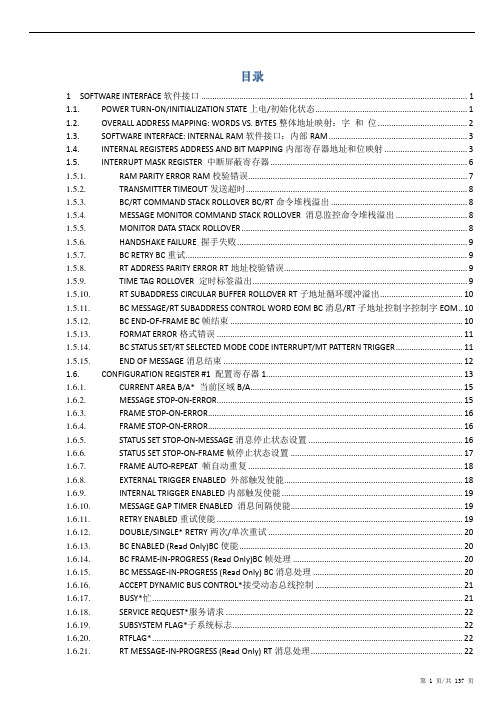
目录
1 SOFTWARE INTERFACE 软件接口 ....................................................................................................................... 1 1.1. POWER TURN-ON/INITIALIZATION STATE 上电/初始化状态 .................................................................... 1 1.2. OVERALL ADDRESS MAPPING: WORDS VS. BYTES 整体地址映射:字 和 位 ........................................ 2 1.3. SOFTWARE INTERFACE: INTERNAL RAM 软件接口:内部 RAM .............................................................. 3 1.4. INTERNAL REGISTERS ADDRESS AND BIT MAPPING 内部寄存器地址和位映射 ..................................... 3 1.5. INTERRUPT MASK REGISTER 中断屏蔽寄存器 ........................................................................................ 6 1.5.1. RAM PARITY ERROR RAM 校验错误..................................
Dell EMC Repository Manager 版本 3.3.2 故障排除指南说明书
Dell EMC Repository Manager Version 3.3.2 Troubleshooting GuideNotes, cautions, and warningsA NOTE indicates important information that helps you make better use of your product.A CAUTION indicates either potential damage to hardware or loss of data and tells you how to avoidA WARNING indicates a potential for property damage, personal injury, or death.© 2019 - 2021 Dell Inc. or its subsidiaries. All rights reserved. Dell, EMC, and other trademarks are trademarks of Dell Inc. or its subsidiaries. Other trademarks may be trademarks of their respective owners.Chapter 1: Overview (4)What's new in this release (4)Enhancements (4)Prerequisites for installing DRM (5)Hardware requirements (5)Software requirements (5)Optional requirements (5)Accessing support content from the Dell EMC support site (5)Other documents you may need (6)DUP Dependencies (6)Creating repository (6)Creating manual repository (7)Creating repository with inventory (7)Creating repository with iDRAC and OME integration (8)Creating repository with VMware integration (9)Creating repository with console integration (10)Creating deployment tools (11)Creating deployment tool_Smart bootable ISO (11)Best practice for creating bootable CD or USB keys for updates (12)Creating deployment tool_Smart deployment script (14)Creating deployment to shared location (14)Configuring settings (15)Configuring network settings (15)Configuring email configuration (15)Creating store settings (16)Configuring plugin settings (16)Configuring catalog settings (17)Comparing repository (17)Appendix A: Frequently asked questions (19)Contents31Overview The Dell EMC Repository Manager (DRM) ensures that the Dell systems are up-to-date with the latest BIOS, driver, firmware,and software. DRM allows you to:●Create repositories of customized component(s) and updates.●Create groups of related updates for systems running the Microsoft Windows and Linux operating system.●Generate comparison reports. Update baselines of custom repositories and generate deployment tools.The customized repositories are made up of Dell EMC Update Packages (DUPs) or Non-DUPs (such as .exe, .msi, .bin orany other file formats) files. DUPs are software utilities provided to update specific software and firmware components.You can arrange these components to group the related updates together. Every repository has a catalog.xml file and it specifies the content of the repository. DRM also has catalog.xml.gz and catalog.gz files. You can import the repository content in two formats, however, you can export the repository content in catalog.xml format only. The file downloaded from /catalog is digitally signed to ensure system security.Topics:•What's new in this release•Enhancements•Prerequisites for installing DRM•Accessing support content from the Dell EMC support site•Other documents you may need•DUP Dependencies•Creating repository•Creating deployment tools•Configuring settings•Comparing repositoryWhat's new in this release●Support for windows server 2022.●Support for Virtual storage area network(vSAN) catalog.EnhancementsThis section describes the enhancements made in this release to DRM.●Enhanced the security aspects.●Enhanced the proxy connections.4OverviewPrerequisites for installing DRMThis section lists the specific prerequisites to be considered before installing DRM.Hardware requirementsTable 1. Hardware requirementsRequirement DetailsProcessor 1 GHz Pentium processor or equivalentRAM 4 GBHard Disk 1 GB of available spaceDisplay1024 x 768 high color, 32-bitOptical Drive (Optional)CD/DVD writerSoftware requirementsDRM works on a wide range of Operating Systems for Windows and Linux. Listed are the specific Operating Systems that DRM is tested with:●Microsoft Windows Server 2016●Microsoft Windows Server 2019●Microsoft Windows 10 (64-bit)●RedHat Enterprise Linux 8.0●RedHat Enterprise Linux 7.7●SUSE Linux 15●Ubuntu 18.04Optional requirements● – To access, create, work with bundles, update catalogs, plug-ins, and repositories.You can use the local repositories on DRM without internet connectivity.● – To create a bootable CD/DVD or bootable USB.Accessing support content from the Dell EMC support siteAccess supporting content related to an array of systems management tools using direct links, going to the Dell EMC support site, or using a search engine.●Direct links:○For Dell EMC Enterprise Systems Management and Dell EMC Remote Enterprise Systems Management—https:// /esmmanuals○For Dell EMC Virtualization Solutions—/virtualizationsolutions○For Dell EMC OpenManage—https:///openmanagemanuals○For iDRAC—https:///idracmanuals○For Dell EMC OpenManage Connections Enterprise Systems Management—https:/// OMConnectionsEnterpriseSystemsManagement○For Dell EMC Serviceability Tools—https:///serviceabilitytools●Dell EMC support site:1.Go to https:///support.Overview52.Click Browse all products.3.From the All products page, click Software, and then click the required link.4.Click the required product and then click the required version.Using search engines, type the name and version of the document in the search box.Other documents you may needIn addition to this guide, you can access the following guides available at the support site..●Dell EMC Repository Manager Quick Installation Guide●Dell EMC System Update User’s Guide●Dell EMC Systems Management - OpenManage Software Support Matrix●Dell EMC Update Packages User's Guide●Dell EMC Server Update Utility User's Guide●Dell EMC OpenManage Server Administrator Installation Guide●Dell EMC OpenManage Essentials User's Guide●Dell EMC OpenManage Enterprise User's Guide●Dell EMC OpenManage Integration for VMware vCenter●Dell EMC OpenManage Integration for Microsoft System Center Version 7.1 for System Center Configuration Manager andSystem Center Virtual Machine ManagerDUP DependenciesThis feature articulates the relationship between two different DUPs. SUU enables certain rules and submissions to determine if a set of conditions or requirements are met. These conditions or requirements are called dependencies. Dependency exists when a DUP of a particular kind has a dependency on additional DUP for further execution. This helps the users to determine, which DUP to install first and which one to follow. There are two types of dependencies:●Hard Dependency — Dependency that must be applied in order to be able to apply the update.In certain scenarios, for a complete update or upgrade, you must install two and more DUPs. It is possible that for Creating repositoryDRM enables you to create a repository of components that allows you to deploy multiple updates in one instance.The user scenarios in this chapter describes the process of creating repositories.6OverviewCreating manual repositoryThis flowchart describes the process to create a manual repository in DRM.Creating repository with inventoryThis flowchart describes the process to create a repository with inventory in DRM.Overview7Creating repository with iDRAC and OME integrationThis flowchart describes the process to create a repository with iDRAC, OpenManage Enterprise, OpenManage Essentials, and OpenManage Integration with Microsoft System Center for SCCM and SCVMM integrations.8OverviewCreating repository with VMware integrationThis flowchart describes the process to create a repository with VMware integration in DRM.Overview9Creating repository with console integrationThis flowchart describes the process to create a repository with console integration in DRM. You can use this methodfor OpenManage Integration for Microsoft System Center Configuration Manager, Microsoft System Center Virtual Machine Manager (OMIMSSC), and OpenManage Enterprise.10OverviewCreating deployment toolsThis chapter describes the process to export the repository as deployment tool type.Creating deployment tool_Smart bootable ISOThis section describes the process to export a repository as Smart Bootable ISO.Overview11Best practice for creating bootable CD or USB keys for updatesYou can create bootable USB keys for updates, using any third party or free tool. You can start your managed system by the bootable CD or USB storage. After the system starts, it automatically runs the selected updates. After the update is complete,Rufus and UNetBootin are third-party software. Install and use these software at your own risk. Dell EMC sharesCreating bootable USB keys using UNetBootinTo create bootable USB keys, using the tool UNetBootin:1.Download the UNetBootin for Windows or Linux available at https://unetbootin.github.io/.2.Run the Dell Repository Manager and generate the bootable ISO.3.Start UNetBootin and select the Diskimage option.4.Click […] adjacent to the ISO drop-down menu and navigate to the ISO created by Dell Repository Manager.5.Ensure that the type setting is equal to USB drive and the location where you want to download the USB key displays in thedrive drop-down menu.6.Click OK to start the USB writing.7.After the USB key writing is complete, insert the USB key into a USB port on the system you want to upgrade.8.Press <F11>.The boot menu is displayed.9.Select option 1 in the UNetBootin boot menu to proceed with the component updates.To create bootable USB keys, using non-graphical user interface, provide the following command line:>unetbootin method=diskimage isofile="/home/user/LinuxISO.iso" installtype=USBtargetdrive=/dev/sdc1Creating bootable USB keys using Rufus toolTo create bootable USB keys, using Rufus tool.1.Download the latest version of Rufus for Windows available at https://rufus.ie/en_IE.html12Overview2.Run the Dell Repository Manager and generate the bootable ISO.3.Start Rufus and select the Disk or ISO image option.4.Click Select adjacent to the Boot Selection and navigate to the ISO created by Dell Repository Manager.5.Ensure to choose MBR Partition Type and BIOS target system with VFAT file system.6.Click OK to start the USB writing.7.After the USB key writing is complete, insert the USB key into a USB port on the system you want to upgrade.8.Press <F11>. The boot menu is displayed.9.Select the USB key as the boot target.10.Select option 1 in the Rufus boot menu to proceed with the component updates.Overview13Creating deployment tool_Smart deployment script This section describes the process to export a repository as Smart deployment script.Creating deployment to shared locationThis section describes the process to export a repository to a common shared location.14OverviewConfiguring settingsThis section describes the process to configure the settings or application preferences.Configuring network settingsThis section describes the process to configure network settings in DRM.Configuring email configurationThis section describes the process to configure email settings in DRM.Overview15This section describes the process to configure data store settings in DRM.Configuring plugin settingsThis section describes the process to configure plugin settings in DRM.16OverviewThis section describes the process to configure catalog settings in DRM.Comparing repositoryThis section describes the process to compare a repository against latest catalog loaded in DRM.Overview1718OverviewFrequently asked questions This section lists some frequently asked questions about DRM.Why is DRM not recognized?After installing DRM on Microsoft Windows operating system, when you try to run any DRM commands, the following error message is displayed: drm is not recognized as an internal or external command, operable program or batch file.Rerun the DRM service file DRM_Service.bat as an Administrator from the installer location. Example of an installer location: C:\Program Files\Dell\Dell EMC Repository Manager\DRM_Service.batWhy I am not able to create repository with inventory file and custom catalogs in different network paths in CLI?To create a repository using a network share, ensure that the inventory file and custom catalogs are in the same network. Why am I not able to run a smart script job from CLI?When you schedule a smart script job with any path set as a network path, an authentication error message is displayed.When providing the location of the script, ensure that there is no tailing slash (\) at the end of the path.Why am I unable to delete a component from a repository using DRM commands through CLI?When you add more than one component in a command separating them with a comma, and if you have provided a space after the comma, the component mentioned after the comma is ignored.Remove the space before mentioning the component name, and then run the delete operation.Accessing DRM is taking longer time when too many catalogs imported?When there are more catalogs that are added to a repository, performance of DRM is impacted.It is recommended to add a maximum number of 10 catalogs and delete catalogs that are not in use.How to delete DRM database?Stop the DRM services, and then delete the following folders:●For Windows: C:\ProgramData\Dell\drm\database●For Linux: /var/dell/drm/log/databaseFrequently asked questions19If you have administrative privileges, ensure that you unhide all the hidden folders in Microsoft Windows operating Where is the Dell EMC Repository Manager runtime log located?DRM creates the log file at runtime in the following location:●Windows: C:\ProgramData\Dell\drm●Linux: /var/dell/drm/logYou can save or email the logs through Save and Mail Logs option in the Dell EMC drop-down menu.Can DRM be run through a Proxy Server?Yes, install DRM inside the firewall and connect to a catalog located outside the firewall ( or a local repository) through a proxy server. You can then use Dell Repository Manager to customize the catalog as per the requirement and store the customized catalog inside the firewall.For more information about setting proxy, see Configuring network settings in the DRM User Guide.If proxy server credentials are changed, ensure that you change the proxy credentials in DRM as well.Why is the proxy password not displayed when refreshing an inventory?The proxy password field may be empty when refreshing an integration repository that was created using a proxy server. Enter the proxy password, and then click Refresh.Why am I seeing 0-1, 0-2, and so on in hours selectiondrop-down menu?In the refresh repository window, if you click the down arrow key when the time is displayed as "00:00", it changes to "0-1". After clicking it again, it turns to "0-2" and so on.Use the up arrow key to set the hour value.How do I edit the ‘.sh’ file in Linux deployment script bundle? Is there any recommended tool to edit this file? Notepad++ editor is recommended for editing the Linux-based file extension on a Microsoft Windows operating system. If you want to edit the extension of the file on a Linux operating system, vi editor is recommended.I am facing access denied issues in Linux operating system. How do I proceed further?Ensure that you have Read and Write access to the drmuser account in the particular directory including all sub-level directories and files when you want to export, import, or download a repository, add a catalog, update a plug-in or configure the storage location in Application Preferences.20Frequently asked questionsI saved a file in the mapped network location. However, I am not able to access location from DRM. What do I do now? Ensure that you have privileges to access the location and then login with the appropriate credentials.I am not able to automatically discover the Microsoft Exchange Web Service URL when trying to configure the email notifications. Is there any other option to discover the URL apart from updating it manually?From DRM version 3.0 onwards, the autodiscovery of Microsoft Exchange Web Server URL is not supported. Update the URL manually.I get a message “GLX version 1.2 or higher is required”when I try to open a Linux terminal window. This message is observed in SUSE Linux 11 and 12.This is a warning message and does not affect the functionality of the product.I am not able to create an inventory repository using a specific catalog and inventory file through command-line interface. How do I proceed?Ensure that the catalog and inventory are available in the same network location and then create a repository.Where can I change the DUP sequence order in DRM 3.x before exporting to a deployment format?You can no longer customize the sequence to install DUPs. Starting from DRM 3.0, the smart deployment feature now run DSU at install time on a server configuration to determine the proper order to install the DUPs. DRM ensures that iDRAC is the last update to run, and the sequence for rest of the DUPs is taken care by DSU.I am not able to install DRM in a custom location on Linux operating system. How do I proceed with the installation?It is recommended to use the default path only for installing DRM. By default, the installer location is set to /opt/dell.Frequently asked questions21After I delete a bundle, it is not deleted from the bundle list on the GUI. Should I delete it elsewhere so that it is updated on the GUI?If the size of a bundle or a collection of bundles that are selected to be deleted exceeds 1 GB, several minutes may be required to delete and reflect the progress on the GUI. The workaround is to wait for sometime for the GUI to reflect the change or exit from the DRM console and reopen the DRM application.I have installed the latest version of DRM on my system, and I am trying to downgrade to one of the previous versions. However, I am not able to proceed further. What do I do now?Reverting to the previous version of DRM is not supported in the current version of the DRM installer . To install an earlierDRM 2.0 and DRM 3.x.x can co-exist on the same system.Why import of plugins are failing?When importing plugins from the exported repository using Smart Deployment Script deployment job, the plugins are not imported because the corresponding sign files are not available.Manually download the plug-in and sign files from support site and have them in the same location.Why am I not able to upgrade or reinstall DRM?When a few files inside the install path: C:\Program Files\Dell\Dell EMC Repository Manager are removed or deleted without following a proper uninstallation process and you try to upgrade DRM, you get the following error message: One or more newer versions of the product are already installed. An upgrade is not applicable. To upgrade DRM:●For Windows operating system—Delete the product element that is named Dell EMC Repository Manager presentin .com.zerog.registry file in C:\Program Files\Zero G Registry folder and then reinstall DRM.●For Linux operating system—Delete the product element that is named Dell EMC Repository Manager presentin .com.zerog.registry file in \var folder and then reinstall DRM.To resolve any DRM related issues, it is recommended to use Repair option after launching DRM's install window instead of the Uninstall option.Ensure that you view all the hidden items because Zero G Registry is a hidden folder.For example, when you search for Dell EMC Repository Manager, the following product element is found:<product name="Dell EMC Repository Manager" id="da88caaa-1f2c-11b2-862b-b8c367dd4f00" upgrade_id="5addbe2f-1f41-11b2-91ce-954f877e94a0" version="3.3.0.627" copyright="2019"info_url="" support_url="" location="C:\Program Files\Dell\Dell EMC Repository Manager"last_modified="2019-12-27 18:07:23">. Delete the entire product element, and then save the file.22Frequently asked questionsUninstalling or downgrading DRM leaves the DRM database and repository DUP packages present in storageTo reclaim storage space of the operating system boot drive after uninstalling DRM, the following directories and content need to be manually removed:●Windows: \ProgramData\Dell\DRM●Linux: /var/dell/drmIf installing a previous DRM version these directories must be removed first as an older DRM version does not support a newer DRM database.Unable to connect to proxy when proxy password contains special charactersChange the password of the proxy which can contain only the special characters like "_", "@", "#", "\", "-", "!", ".", "$", "%", "&", "*" and retry setting the proxy.Frequently asked questions23。
Unicore Protocol Specification UM220-III_Rel_Ed1
目录1概述 (1)1.1消息的格式 (1)1.2校验和 (1)1.3数据类型 (2)2消息定义 (3)2.1Common Message (3)2.1.1PDTINFO (3)2.1.2RESET (3)2.1.3OK (4)2.1.4FAIL (4)2.2Config Message (4)2.2.1CFGPRT (4)2.2.2CFGMSG (5)2.2.3CFGNAV (6)2.2.4CFGTP (7)2.2.5CFGEM (8)2.2.6CFGNMEA (8)2.2.7CFGSYS (9)2.2.8CFGDYN (9)2.2.9CFGSAVE (10)2.2.10CFGLOAD (10)2.2.11CFGCLR (11)2.3NMEA Message (11)2.3.1GGA (11)2.3.2GLL (12)2.3.3GSA (13)2.3.4GSV (14)2.3.5RMC (14)2.3.6VTG (16)2.3.7ZDA (16)2.3.8GST (17)2.4Navigation Result Message (17)2.4.1NAVPOS (17)2.4.2NAVVEL (18)2.4.3NAVTIME (18)2.5Misc Message (19)2.5.1ANTSTAT (19)3默认配置 (20)3.1串口设置(CFGPRT) (20)3.2消息设置(CFGMSG) (20)3.3定位配置(CFGNAV) (20)3.4授时配置(CFGTP) (20)3.5外部触发事件配置(CFGEM) (21)3.6NMEA配置(CFGNMEA) (21)3.7卫星系统配置(CFGSYS) (21)1概述1.1消息的格式在Unicore协议中,输入和输出的语句被统称为消息。
每条消息均为全ASCII字符组成的字符串。
消息的基本格式为:$MSGNAME,data1,data2,data3,…[*CC]\r\n所有的消息都以'$'(0x24)开始,后面紧跟着的是消息名。
报告队列中的错误_错误应用程序w...

报告队列中的错误: 错误应用程序w3wp.exe,版本 6.0.3790.3959,错误模块unknown报告队列中的错误: 错误应用程序 w3wp.exe,版本 6.0.3790.3959,错误模块 unknown,版本0.0.0.0,错误地址 0x00690062。
, Windows Sharepoint 3.0 错误事件类型: 信息事件来源: Application Error事件种类: (100)事件 ID: 1004日期: 2007-6-16事件: 12:52:29用户: N/A计算机: DC描述:报告队列中的错误: 错误应用程序 w3wp.exe,版本 6.0.3790.3959,错误模块 unknown,版本 0.0.0.0,错误地址 0x00690062。
有关更多信息,请参阅在 /fwlink/events.asp 的帮助和支持中心。
数据:0000: 41 70 70 6c 69 63 61 74 Applicat0008: 69 6f 6e 20 46 61 69 6c ion Fail0010: 75 72 65 20 20 77 33 77 ure w3w0018: 70 2e 65 78 65 20 36 2e p.exe 6.0020: 30 2e 33 37 39 30 2e 33 0.3790.30028: 39 35 39 20 69 6e 20 75 959 in u0030: 6e 6b 6e 6f 77 6e 20 30 nknown 00038: 2e 30 2e 30 2e 30 20 61 .0.0.0 a0040: 74 20 6f 66 66 73 65 74 t offset0048: 20 30 30 36 39 30 30 36 00690060050: 32 2事件类型: 审核失败事件来源: MSSQL$MICROSOFT##SSEE事件种类: (4)事件 ID: 18452日期: 2007-6-15事件: 19:26:02用户: N/A计算机: DC描述:事件 ID ( 18452 )的描述(在资源( MSSQL$MICROSOFT##SSEE )中)无法找到。
[转scrum]Scrum的三个物件
![[转scrum]Scrum的三个物件](https://img.taocdn.com/s3/m/cd8fc29003d276a20029bd64783e0912a2167c9c.png)
[转scrum]Scrum的三个物件========================================================Scrum的三个物件: Product Backlog, Sprint Backlog 和Burndown Chart.Product Backlog在项⽬开始的时候,Product Owner要准备⼀个根据商业价值排好序的客户需求列表。
这个列表就是Prodct Backlog,⼀个最终会交付给客户的产品特性列表,它们根据商业价值来排列优先级。
Scrum team会根据这个来做⼯作量的估计Product backlog应该涵盖所有⽤来构建满⾜客户需要的产品特性,包括技术上的需求。
⾼优先级的⼀些产品特性需要⾜够的细化以便于我们做⼯作量估计和做测试。
对于那些可以在下个Sprint中完成的Product Backlog功能点,⼤约10⼈天的⼯作量的粒度就不错了。
对于那些以后将要实现的特性可以不够详细。
Sprint BacklogSprint Backlog 是Sprint规划会上产出的内容. 当Scrum team选择并承诺了Product backlog中要递交的⼀些⾼优先级的产品功能点后,这些功能点就会被细化成为Sprint Backlog:⼀个完成Product Backlog功能点的必需的任务列表.这些点会被细化为更⼩的任务,⼯作量⼩于2天。
Sprint backlog完成后,Scrum team会根据它重新估计⼯作量,如果这些⼯作量和原始估计的⼯作量有较⼤差异,Scrum team和Product Owner 协商,调整合理得⼯作量到Sprint中,以确保Sprint的成功实施。
Burndown ChartBurndown Chart 显⽰了Sprint中累积剩余的⼯作量,它是⼀个反映⼯作量完成状况的趋势图。
在Sprint开始的时候,Scrum Team会标⽰和估计在这个Sprint需要完成的详细的任务。
scottplot addsignalxy函数占用太多内存 -回复

scottplot addsignalxy函数占用太多内存-回复问题的前提是“ScottPlot AddSignalXY函数占用太多内存”。
要解决这个问题,首先需要了解ScottPlot和AddSignalXY函数的基本概念,然后分析可能导致内存占用过高的原因,并提出解决方案。
ScottPlot是一个用于绘制数据图表的开源库,使用C#语言编写。
它提供了许多功能强大且易于使用的绘图工具,可用于创建各种类型的图表,包括线图、散点图、柱状图等。
AddSignalXY函数是ScottPlot库中的一个函数,用于将数据点添加到图表中的信号图层。
然而,使用AddSignalXY函数时可能会遇到内存占用过高的问题。
造成这个问题的原因可能有以下几点:1. 数据量过大:如果要绘制的数据量非常庞大,使用AddSignalXY函数将数据点一次性添加到图表中可能会导致内存占用过高。
内存中需要保存绘图数据的副本,因此数据越多,内存占用就越高。
2. 数据频繁更新:如果使用AddSignalXY函数不断地添加新的数据点,而不是一次性添加所有数据点,那么每次添加都会导致一次内存分配和数据复制操作,从而增加了内存占用。
如果更新频率非常高,内存占用会持续增长。
3. 内存泄漏:某些情况下,调用AddSignalXY函数可能会导致内存泄漏。
比如在每次更新图表时没有正确释放旧的数据,或者使用了不必要的缓存机制,导致无用的数据一直占据内存。
针对上述问题,可以采取以下解决方案:1. 数据分批加载:如果数据量非常大,可以考虑将数据分成多个批次加载到图表中,而不是一次性加载。
可以使用分页加载或者按需加载的方式实现这一目标。
这样可以降低内存占用,并在绘制过程中提高性能。
2. 数据流式更新:如果数据需要频繁更新,可以考虑使用数据流方式更新图表,而不是每次都使用AddSignalXY函数。
可以使用数据队列缓存新的数据点,并定时或根据某个条件更新数据,从而减少内存占用。
