2010年4月16大城市燃气灶前10名市场占有率(%)及均价(元)
iv16PowerTools2010

i 6Pw r os 以提 供 对Wi o s v o e ol 1 T 可 n w 系统 的全 d 面 管理 、 控制 , 用于注 册 表 、 可 文件 系统 和本地 网 络 的监 控与优 化 。 册 表 工 具 可 以维 护Wid w 注 no s 添 加/ 除软件 列 表 , 载 软件 , 删 卸 扫描 注 册 表 中 的 无 效 键 值 , 除 无 效 内容 , 删 控制 系 统 启动 时 加 载 的程 序 , 问远 程 电脑 的注 册 表 。 访 文件 系统 工 具 能 搜 索本 地 或远 程 电脑 中 的零 长度 文件 、 复 文 重 件、 临时 文件 、 效快 捷方 式 等。 无 局域 网工具 可以 运行 远 程 电脑 中的程 序 、 发送 消息 、 即时聊 天 、 远 程 控 制 登 陆/ 机 / 起 、 程任 务 管 理 等 。 统 关 重 远 系 在 经 过 长时 间 的使 用 后 , 会 出现各 种 各样 的问 总 题, 如系统 运行 不稳 定 , 系统运 行缓 慢 等等 。 实 其 出现 这 样 的原 因大 多是 因为系统 中频 繁 的安 装 或 者 卸 载 软件 , 致 系统 中残 留着 大 量 的无 用文 件 导 和 垃圾 文件 导 致 系统运 行 缓 慢 , 至会 造成 系 统 甚 运行 错 误 重 启等 等 , 要 的时候 我们 需要 使 用 软 必 件来 对 其进 行 优化 , 而这 款 工具 正 给我 们 提供 了 比较全 面 的优化功 能 , 用它 , 以快速 进 行系统 使 可 优化和 减肥 。
do wnlad. fn o h rI
◇
软 件 版 本 :20 . 软件大小 :89 MB .6 ◇ 软件性质 :共享软件 ◇ 适 用 平 台 :W ix /i awi72 0 /0 3 n pvs J n /0 02 0 t ◆ 下 载 地 址 :ht:www.nie o .e/ t / p/ o l d wnn t n
戴尔 PowerEdge T410 产品说明书

高性能的英特尔至强5500和5600系列处理器、多达六硬盘(3.5英寸或2.5英寸)的配置、DDR3内存,以及24英寸的理想机箱深度,均有助于提高Dell PowerEdge T410的部署和运行效率。
PowerEdge T410采用有针对性的设计,拥有能源优化技术和简化的系统管理。
有针对性的设计PowerEdge T410具备戴尔卓越的系统通用性和可靠性。
一致的组件布局和精心配置的接口端口及电源,为安装和重新部署提供了便利。
PowerEdge T410深度为24英寸的机箱易于使用,非常适合需要小型机箱和安静办公的后端办公室、零售或小型办公室环境。
坚固的金属硬盘支架与排列有序的布线设计,有助于改善组件存取和服务器内部的通风。
悄无声息的静音设计,以及挡板正面方便监控的可选液晶屏,均体现了PowerEdge 410的针对性设计。
能源优化技术智能节能技术深入PowerEdge T410系统的核心。
多项能源调整技术和符合标准的智能节能组件可降低能耗,同时提高性能。
PowerEdge系统配备能效超过90%的智能节能电源装置,合乎系统的要求。
功率封顶、功率清点和功率预算等电源管理功能,可根据您的特定环境对电源进行最有效的管理。
简化的系统管理新一代Dell OpenManage™管理工具套件能提供高效的操作方式和标准化的命令,可与现有系统集成以实现有效控制。
戴尔管理控制台(DMC)将基础架构管理缩减至一个控制台,从而帮助简化操作并提高稳定性。
此控制台可在单一视图中显示整个基础架构,并为整个基础架构提供通用数据源。
它基于Symantec™ 管理平台而构建,拥有可轻松扩展的模块化基础,能提供基本的硬件管理功能,或资产和安全性管理等更为高级的功能。
戴尔管理控制台能够减少或避免手动流程,使您能够节约时间和资金以用于更具战略性的技术。
戴尔生命周期控制器通过单一访问点提供“即时启用”的集成管理功能,安全而高效。
统一服务器配置器(USC)界面嵌入并集成在系统中,以大幅提升灵活性与功能,并可为您提供永久的工具存取途径。
T410 内存

T410系统内存您的系统可支持多个 DDR3 已注册的内存模块 (RDIMM) 或 ECC 非缓冲内存模块 (UDIMM)。
单列或双列内存模块可以为 1067 MHz 或 1333 MHz,四列内存模块可以为 1067 MHz。
系统包含八个内存插槽,分为两组(每组四个),每个处理器一组。
每组的四个插槽中,两个 DIMM 用于通道 0,其余的通道 1 和 2 各使用一个。
每个通道的第一个插槽上都标有白色释放拉杆。
系统支持的最大内存取决于所用的内存模块类型和大小:∙对于大小为 2-GB、4-GB 和 8-GB(如果有)的单列和双列 RDIMM,支持的总容量最大为 64 GB。
∙四列 RDIMM 总共最多可支持的最大总容量为 4 GB。
∙对于 1 GB 和 2 GB 的 UDIMM,支持的最大总容量为 16 GB。
内存模块一般安装原则为确保获得最佳系统性能,请在配置系统内存时遵守以下通用原则。
注:配置内存时如果不遵循这些原则,将会使系统无法启动或无法产生任何视频输出。
∙不能混合安装 RDIMM 和 UDIMM。
∙除了未使用的内存通道之外,所有被占用的内存通道的配置必须相同。
∙在双处理器配置中,每个处理器的内存必须配置相同。
∙可以在内存信道中混合使用不同大小的内存模块(例如:2 GB 和 4 GB),但所有占用的信道必须配置相同。
这只适用于通道 0。
∙对于优化器模式,内存模块按照插槽的数字顺序安装,以 A1 或 B1 开始。
∙对于 Memory Mirroring(内存镜像)或 Advanced ECC Mode(高级 ECC 模式),距离处理器最远的插槽将不使用,内存模块会从插槽 A1 或 B1 开始,然后依次是插槽 A2 或 B2。
∙Advanced ECC Mode(高级 ECC 模式)所需的内存模块使用的是 x4 或 x8 DRAM 设备宽度。
∙每个通道的内存速度因内存配置而异:o对于单列或双列内存模块:o每个通道一个内存模块时最多支持 1333 MHz。
NVIDIA T4虚拟化技术简介说明书
TB-09377-001-v01 | January 2019 Technical Brief09377-001-v01TABLE OF CONTENTSPowering Any Virtual Workload (1)High-Performance Quadro Virtual Workstations (3)Deep Learning Inferencing (5)Virtual Desktops for Knowledge Workers (7)Summary (8)The NVIDIA® T4 graphics processing unit (GPU), based on the latest NVIDIA Turing™architecture, is now supported for virtualized workloads with NVIDIA virtual GPU(vGPU) software. Using the same NVIDIA graphics drivers that are deployed on non-virtualized systems, NVIDIA vGPU software provides Virtual Machines (VMs) with thesame breakthrough performance and versatility that the T4 offers to a physicalenvironment.NVIDIA initially launched T4 at GTC Japan in the Fall of 2018 as an AI inferencingplatform for bare metal servers. When T4 was initially released, it was specificallydesigned to meet the needs of public and private cloud environments as their scalability requirements continue to grow. Since then there has been rapid adoption and it was recently released on the Google Cloud Platform. The T4 is the most universal graphics processing unit (GPU) to date -- capable of running any workload to drive greater data center efficiency. In a bare metal environment, T4 accelerates diverse workloads including deep learning training and inferencing. Adding support for virtual desktops with NVIDIA GRID® Virtual PC (GRID vPC) and NVIDIA Quadro® Virtual Data Center Workstation (Quadro vDWS) software is the next level of workflow acceleration.The T4 has a low-profile, single slot form factor, roughly the size of a cell phone, anddraws a maximum of 70 W power, so it requires no supplemental power connector. This highly efficient design allows NVIDIA vGPU customers to reduce their operating costs considerably and offers the flexibility to scale their vGPU deployment by installing additional GPUs in a server, because two T4 GPUs can fit into the same space as a single NVIDIA® Tesla® M10 or Tesla M60 GPU, which could consume more than 3X the power.Powering Any Virtual WorkloadFigure 1. NVIDIA Tesla GPUs for Virtualization WorkloadsThe NVIDIA T4 leverages the NVIDIA Turing™ architecture – the biggest architectural leap forward in over a decade – enabling major advances in efficiency and performance. Some of the key features provided by the NVIDIA Turing architecture include Tensor Cores for accelerating deep learning inference workflows as well as NVIDIA® CUDA®cores, Tensor Cores, and RT Cores for real-time ray tracing acceleration and batch rendering. It’s also the first GPU architecture to support GDDR6 memory, which provides improved performance and power efficiency versus the previous generation GDDR5.The T4 is an NVIDIA RTX™-capable GPU, benefiting from all of the enhancements of the NVIDIA RTX platform, including:④Real-time ray tracing④Accelerated batch rendering④AI-enhanced denoising④Photorealistic design with accurate shadows, reflections, and refractionsThe T4 is well suited for a wide range of data center workloads including:④Virtual Desktops for knowledge workers using modern productivity applications④Virtual Workstations for scientists, engineers, and creative professionals④Deep Learning Inferencing and trainingThe graphics performance of the NVIDIA T4 directly benefits virtual workstations implemented with NVIDIA Quadro vDWS software to run rendering and simulation workloads. Users of high-end applications, such as CATIA, SOLIDWORKS, and ArcGIS Pro, are typically segmented as light, medium or heavy based on the type of workflow they’re running and the size of the model/data they are working with. The T4 is a low-profile, single slot card for light and medium users working with mid-to-large sized models. T4 offers double the amount of framebuffer (16 GB) versus the previous generation Tesla P4 (8 GB) card, therefore users can work with bigger models within their virtual workstations. Benchmark results show that T4 with Quadro vDWS delivers 25% faster performance than Tesla P4 and offers almost twice the professional graphics performance of the NVIDIA Tesla M60.High-Performance Quadro Virtual WorkstationsFigure 2. T4 Performance Comparison with Tesla M60 and Tesla P4 Based on SPECviewperf13The NVIDIA Turing architecture of the T4 fuses real-time ray tracing, AI, simulation, and rasterization to fundamentally change computer graphics. Dedicated ray-tracing processors called RT Cores accelerate the computation of how light travels in 3D environments. NVIDIA Turing accelerates real-time ray tracing over the previous-generation NVIDIA® Pascal™ architecture and can render final frames for film effects faster than CPUs. The new Tensor Cores, processors that accelerate deep learning training and inference, accelerate AI-enhanced graphics features—such as denoising, resolution scaling, and video re-timing—creating applications with powerful new capabilities.Figure 3. Benefits of Real-Time Rendering with NVIDIA RTX TechnologyThe T4 with the NVIDIA Turing architecture sets a new bar for power efficiency and performance for deep learning and AI. Its multi-precision tensor cores combined with accelerated containerized software stacks from NVIDIA GPU Cloud (NGC) delivers revolutionary performance.As we are racing towards a future where every customer inquiry, every product and service will be touched and improved by AI, NVIDIA vGPU is bringing Deep Learning inferencing and training workflows to virtual machines. Quadro vDWS users can now execute inferencing workloads within their VDI sessions by accessing NGC containers. NGC integrates GPU-optimized deep learning frameworks, runtimes, libraries and even the OS into a ready-to-run container, available at no charge. NGC simplifies and standardizes deployment, making it easier and quicker for data scientists to build, train and deploy AI models. Accessing NGC containers within a VM offers even more portability and security to virtual users for classroom environments and virtual labs. Test results show that Quadro vDWS users leveraging T4 can run deep learning inferencing workloads 25X faster than with CPU-only VMs.Deep Learning InferencingFigure 4. Run Video Inferencing Workloads up to 25X Faster with T4 and Quadro vDWS vs. a CPU-only VMBenchmark test results show that the T4 is a universal GPU which can run a variety of workloads, including virtual desktops for knowledge workers accessing modern productivity applications. Modern productivity applications, high resolution and multiple monitors, and Windows 10 continue to require more graphics and with NVIDIA GRID vPC software, combined with NVIDIA Tesla GPUs, users can achieve a native-PC experience in a virtualized environment. While the Tesla M10 GPU, combined with NVIDIA GRID software, remains the ideal solution to provide optimal user density, TCO and performance for knowledge workers in a VDI environment, the versatility of the T4 makes it an attractive solution as well.The Tesla M10 was announced in Spring of 2016 and offers the best user density and performance option for NVIDIA GRID vPC customers. The Tesla M10 is a 32 GB dual-slot card which draws up to 225 W of power, therefore requires a supplemental power connector. The T4 is a low profile, 16 GB single-slot card, which draws 70 W maximum and does not require a supplemental power connector.Two NVIDIA T4 GPUs provide 32 GB of framebuffer and support the same user density as a single Tesla M10 with 32 GB of framebuffer, but with lower power consumption. While the Tesla M10 provides the best value for knowledge worker deployments, selecting the T4 for this use case brings the unique benefits of the NVIDIA Turing architecture. This enables IT to maximize data center resources by running virtual desktops in addition to virtual workstations, deep learning inferencing, rendering, and other graphics and compute intensive workloads -- all leveraging the same data center infrastructure. This ability to run mixed workloads can increase user productivity, maximize utilization, and reduce costs in the data center. Additional T4 technology enhancements include support for VP9 decode, which is often used for video playback, and H.265 (HEVC) 4:4:4 encode/decode.The flexible design of the T4 makes it well suited for any data center workload -enabling IT to leverage it for multiple use cases and maximize efficiency and utilization.It is perfectly aligned for vGPU implementations - delivering a native-PC experience for virtualized productivity applications, untethering architects, engineers and designersfrom their desks, and enabling deep learning inferencing workloads from anywhere, onany device. This universal GPU can be deployed on industry-standard servers to provide graphics and compute acceleration across any workload and future-proof the data center. Its dense, low power form factor can improve data center operating expenses while improving performance and efficiency and scales easily as compute and graphics needs grow.NoticeThe information provided in this specification is believed to be accurate and reliable as of the date provided. However, NVIDIA Corporation (“NVIDIA”) does not give any representations or warranties, expressed or implied, as to the accuracy or completeness of such information. NVIDIA shall have no liability for the consequences or use of such information or for any infringement of patents or other rights of third parties that may result from its use. This publication supersedes and replaces all other specifications for the product that may have been previously supplied.NVIDIA reserves the right to make corrections, modifications, enhancements, improvements, and other changes to this specification, at any time and/or to discontinue any product or service without notice. Customer should obtain the latest relevant specification before placing orders and should verify that such information is current and complete.NVIDIA products are sold subject to the NVIDIA standard terms and conditions of sale supplied at the time of order acknowledgement, unless otherwise agreed in an individual sales agreement signed by authorized representatives of NVIDIA and customer. NVIDIA hereby expressly objects to applying any customer general terms and conditions with regard to the purchase of the NVIDIA product referenced in this specification.NVIDIA products are not designed, authorized or warranted to be suitable for use in medical, military, aircraft, space or life support equipment, nor in applications where failure or malfunction of the NVIDIA product can reasonably be expected to result in personal injury, death or property or environmental damage. NVIDIA accepts no liability for inclusion and/or use of NVIDIA products in such equipment or applications and therefore such inclusion and/or use is at customer’s own risk.NVIDIA makes no representation or warranty that products based on these specifications will be suitable for any specified use without further testing or modification. Testing of all parameters of each product is not necessarily performed by NVIDIA. It is customer’s sole responsibility to ensure the product is suitable and fit for the application planned by customer and to do the necessary testing for the application in order to avoid a default of the application or the product. Weaknesses in customer’s product designs may affect the quality and reliability of the NVIDIA product and may result in additional or different conditions and/or requirements beyond those contained in this specification. NVIDIA does not accept any liability related to any default, damage, costs or problem which may be based on or attributable to: (i) the use of the NVIDIA product in any manner that is contrary to this specification, or (ii) customer product designs.No license, either expressed or implied, is granted under any NVIDIA patent right, copyright, or other NVIDIA intellectual property right under this specification. Information published by NVIDIA regarding third-party products or services does not constitute a license from NVIDIA to use such products or services or a warranty or endorsement thereof. Use of such information may require a license from a third party under the patents or other intellectual property rights of the third party, or a license from NVIDIA under the patents or other intellectual property rights of NVIDIA. Reproduction of information in this specification is permissible only if reproduction is approved by NVIDIA in writing, is reproduced without alteration, and is accompanied by all associated conditions, limitations, and notices.ALL NVIDIA DESIGN SPECIFICATIONS, REFERENCE BOARDS, FILES, DRAWINGS, DIAGNOSTICS, LISTS, AND OTHER DOCUMENTS (TOGETHER AND SEPARATELY, “MATERIALS”) ARE BEING PROVIDED “AS IS.” NVIDIA MAKES NO WARRANTIES, EXPRESSED, IMPLIED, STATUTORY, OR OTHERWISE WITH RESPECT TO THE MATERIALS, AND EXPRESSLY DISCLAIMS ALL IMPLIED WARRANTIES OF NONINFRINGEMENT, MERCHANTABILITY, AND FITNESS FOR A PARTICULAR PURPOSE. Notwithstanding any damages that customer might incur for any reason whatsoever, NVIDIA’s aggregate and cumulative liability towards customer for the products described herein shall be limited in accordance with the NVIDIA terms and conditions of sale for the product.TrademarksNVIDIA, the NVIDIA logo, CUDA, NVIDIA GRID, NVIDIA RTX, NVIDIA Turing, Pascal, Quadro, and Tesla are trademarks and/or registered trademarks of NVIDIA Corporation in the U.S. and other countries. Other company and product names may be trademarks of the respective companies with which they are associated.Copyright© 2019 NVIDIA Corporation. All rights reserved.。
T410s win8.1 64位完美驱动双显卡教程
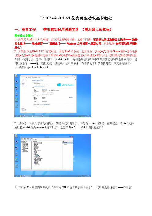
T410Swin8.164位完美驱动双显卡教程一、准备工作禁用驱动程序强制签名(借用别人的教程)简单的文字版本1、如果是Win8(主)双系统,启动到选系统的时候,选最下面的:更改默认值或选择其它选项——>选择其它选项——>疑难解答——>高级选项——>Windows启动设置—重新启动,然后选择“禁用驱动程序强制签名”;2、如果你不是Win8(主)的双系统,或是Win8单系统,进系统后,[Win]+[C]调出Charm菜单-更改电脑设置-设置-常规-高级启动的立即重启-疑难解答-高级选项-启动设置-重新启动,然后禁用驱动强制签名。
在网上找到方法,分享:开机时,按shift+f8,选择系统启动菜单中的禁用驱动强制签名模式启动,就可以安装了。
——这个貌似无效,没按出来启动菜单来,有需要的可以多尝试几次。
图文并茂版本:1、操作系统:Win8Pro x642、设备是一台很久以前的扫描仪,驱动早就不更新了,还好有Vista的驱动,而且就是一个inf文件,所以把ntx86改为ntamd64就可以了,之前在Win7x64上测试通过的!3、不料在Win8里面居然提示“第三方INF不包含数字签名信息”,然后就没得继续了——不给装!以下为解决办法,为了方便阅读,继续上面的序号:4、Charm菜单(就是装好Win8显示你好后面的那个操作方法,在屏幕右侧的角落晃动下鼠标会出现的菜单;如果觉得晃不好的同学直接按[Win]+[C]就可以调出Charm菜单)就是Win8右侧的那个全屏菜单,找到里面的设置。
5、最下面有个更改电脑设置,最新更新:按【Win】+【i】可以不需要上面的第4点,直接打开设置。
6、打开电脑设置后,左侧选择常规,然后右侧选择最后一项立即重启。
对,就是要从这里更改Windows 启动设置。
7、这里的重启超级快,连开机自检的POST都没看到,就切换好了!感觉像打了鸡血一样!!!--!8、这里选择疑难解答9、这里选择高级选项,其实这里还有很多其他选项(例如初始化电脑?),大家看到就行了,不是本文重点,所以略过不提。
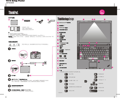
ThinkPad T410 官方 中文 说明书
首先阅读确保遵从下面给出的这些重要技巧,以便充分使用计算机并从中获得无尽乐趣。
如若不然,可能会令您感到不适或受伤,或导致计算机出故障。
当计算机开启或电池充电时,底板、掌托以及某些其他部件可能会发热。
这些部件的温度有多高取决于系统活动的频率和电池的充电程度。
如果与身体接触(即使是透过衣服接触)的时间过长,可能会使您感到不适,甚至还会烧伤皮肤。
- 避免手、膝盖或身体任何其他部位与计算机发热部位长时间接触。
- 定期将手移开掌托,进行适当休息,不要一直使用键盘。
当交流电源适配器连接到电源插座和计算机时,它将产生热量。
如果与身体接触(即使是透过衣服接触)的时间过长,可能会导致皮肤灼伤。
- 请勿将正在工作的交流电源适配器与身体的任何部位接触。
- 切勿使用计算机来取暖。
为避免溅湿和电击危险,请将液体放置在远离计算机的地方。
对电缆施力过大可能会损坏或弄断电缆。
适当布放交流电源适配器、鼠标、键盘、打印机或任何其他电子设备的电缆,使电缆不会被机器或其他物体夹住、践踏、绊倒他人或者处于任何可能妨碍操作计算机的位置。
移动计算机之前,请执行以下操作之一,以确保电源开关指示灯未点亮或闪烁:- 关闭计算机。
- 按 Fn+F4 键将计算机置于睡眠(待机)方式。
- 按 Fn+F12 键将计算机置于休眠方式。
这有助于防止损坏计算机以及可能造成的数据丢失。
请勿摔落、撞击、刮擦、扭曲、击打、震动、挤压计算机、显示屏或外接设备,或在它们的上面放置重物。
- 请使用具有良好防震和保护能力的优质便携包。
- 请勿将计算机放在塞得很满的箱子或包中。
- 将计算机放入便携包之前,请确保该计算机已关闭、处于睡眠(待机)方式(Fn+F4)或休眠方式(Fn+F12)。
请勿将开启状态的计算机放入便携包中。
避开计算机散发的热量。
避开交流电源适配器散发的热量。
避开交流电源适配器散发的热量避免弄湿计算机。
在移动计算机时保护计算机及数据。
避免损坏电缆。
携带计算机时请小心。
t410拆机 (3)

T410拆机拆机是指将一台电子设备分解成单个组件或零部件的过程。
在本文中,我们将介绍如何拆解T410笔记本电脑。
T410是联想公司推出的商用笔记本电脑,广泛应用于办公和商务领域。
在拆机之前,请确保您已备份所有重要数据,并谨慎操作以避免损坏设备。
步骤一:准备工作在开始拆解T410之前,您需要准备以下工具:1.薄刀或塑料刮板2.十字螺丝刀3.镊子4.适当大小的容器用于存放螺丝和零件另外,请确保您工作的环境干净、宽敞,并放置一块柔软的表面以防止设备受损。
步骤二:拆解顶盖1.关闭电源并拔掉所有外部连接设备。
2.在T410的底部找到顶盖上的螺丝孔,并使用十字螺丝刀逐个拧松螺丝。
将螺丝放置在容器中以防丢失。
3.用薄刀或塑料刮板轻轻将薄板从顶盖的缝隙处插入,然后轻轻抬起或滑动薄板,以分离顶盖和底座。
步骤三:分离键盘和内部零件1.打开T410的顶盖,并轻轻反转键盘。
请注意,键盘与主板之间有一根连接线。
不要用力拉动键盘,以免损坏连接线。
2.使用镊子或手指小心地拔掉键盘连接线,将键盘从主板上分离。
3.拆下其他外部组件,如触摸板、指纹识别器等。
请小心处理这些零件,以免损坏。
步骤四:拆卸底座和其他内部组件1.将底座翻转,然后使用十字螺丝刀拧松所有与底座连接的螺丝,将螺丝放入容器中。
2.小心将底座从主板上分离,并拆下其他内部组件,如硬盘驱动器、内存条等。
注意,一些组件可能需要额外的步骤或特定的工具才能拆除。
请参考T410的拆机手册或官方文档以获取详细的指导。
步骤五:清洁和维护在拆解完成后,您可以清洁和维护T410的内部组件。
使用压缩空气罐或软刷小心地清除灰尘和杂物。
如果需要更彻底的清洁,请参考联想官方提供的清洁和维护指南。
步骤六:重新组装完成清洁和维护后,您可以开始重新组装T410。
按照拆解的逆序,将内部组件和底座安装回主板上,并紧固所有螺丝。
确保连接线正确插入,并检查所有连接是否安全稳固。
结论拆解T410可以为您提供更好地了解及维护该设备的机会。
T410完整上电时序

T410完整上电时序IBM T410上电时序IBM T410上电时序一,待机:插入电源适配器,产生AD电压,经保险F2:DCIN_PWR20_F电压,经保险F5,经二极管D10,转换为VREGIN20电压,为待机芯片U61(RINKAN_2)的第59脚VREGIN20供电,57脚BAT_VOLT检测供电正常,从61脚VCC3SW输出VCC3SW待机电压,此电压给U42电源管理芯片(THINKER1)供电。
同时U61第58脚TH_DET串接若干温敏电阻开始工作,检测整机温度。
电源适配器插入被U7(BQ2474)5脚ACDET和28脚PVCC检测到后,会从13脚#EXTPWR发出-EXTPWR信号经Q61转化后送入U42第71脚,U42正常后(供电时钟复位)会从第60脚MON输出M1_ON的其中一路转化为VCC5M_ON和VCC3M_ON送往U41的EN1,EN2引脚提供芯片开启信号。
Q107,Q61,Q51,Q78,R340,R143,R145一起作用控制P沟道MOSQ9的G级保持低电平导通,出现异常,传来低电平有效的-PWRSHUTDOWN或高电平有效的DISCHARGE2有效信号,使Q9G级高电平截止,切断电压源,保护整机。
Q36没有导通时,会有一小部分微弱的“先锋部队式”的电压电流经过它内部的二极管流过,来到VINT20公共点。
U41检测到23脚VINT20电压输入,就会从29脚输出VL5V线性电压。
又有4脚21脚VCC5M_ON,VCC3M_ON信号后,就会从11脚DRVH1,30脚DRVL1,24脚DRVH2,27脚DRVL2分别输出脉冲信号驱动Q16,Q46,Q18,Q17轮流导通,经电感L3,L4滤波储能输出VCC5M,VCC3M待机电压。
这两个电压正常后会反馈给U61第45,42脚后为其提供辅助供电,U61得到此辅助供电会从41脚输出DCIN_DRV驱动信号驱动Q36完全导通,使所有电压电流全部导通,“主力部队”来到公共点。
Windows事件查看器事件代码详解

Windows事件查看器事件代码详解2000 无效的像素格式。
2001 指定的驱动程序无效。
2002 窗口样式或类别属性对此操作无效。
2003 不支持请求的图元操作。
2004 不支持请求的变换操作。
2005 不支持请求的剪切操作。
2010 指定的颜色管理模块无效。
2011 制定的颜色文件配置无效。
2012 找不到指定的标识。
2013 找不到所需的标识。
2014 指定的标识已经存在。
2015 指定的颜色文件配置与任何设备都不相关。
2016 找不到该指定的颜色文件配置2017 指定的颜色空间无效。
2018 图像颜色管理没有启动。
2019 在删除该颜色传输时有一个错误。
2020 该指定的颜色传输无效。
2021 该指定的变换与位图的颜色空间不匹配。
2022 该指定的命名颜色索引在配置文件中不存在。
2102 没有安装工作站驱动程序。
2103 无法定位服务器。
2104 发生内部错误,网络无法访问共享内存段。
2105 网络资源不足。
2106 工作站不支持该操作。
2107 设备没有连接。
2108 网络连接已成功,但需要提示用户输入一个不同于原始指定的密码。
2109 使用默认凭据成功连接网络。
2114 没有启动服务器服务。
2115 队列空。
2116 设备或目录不存在。
2117 无法在重定向的资源上执行此操作。
2118 名称已经共享。
2119 服务器目前无法提供所需的资源。
2121 额外请求的项目超过允许的上限。
2122 对等服务只支持两个同时操作的用户。
2123 API 返回的缓冲区太小。
2127 远程 API 错误。
2131 打开或读取配置文件时出错。
2136 发生一般网络错误。
2137 工作站服务的状态不一致。
重新启动工作站服务之前,请先重新启动计算机。
2138 工作站服务没有启动。
2139 所需信息不可用。
2140 发生 Windows 2000 内部错误。
2141 服务器没有配置事务处理。
2142 远程服务器不支持请求的 API。
联想ThinkPad T410s

纠错集成显卡
显卡芯片
纠错Intel GMA HD(集成于处理器)
显存容量
纠错共享内存容量
显存类型
纠错无
音频
音频系统
纠错内置音效芯片
扬声器
纠错立体声扬声器
摄像头/网络通信
无线网卡
纠错Intel 6200 AGN
网卡描述
纠错集成网卡
蓝牙
纠错支持蓝牙功能
接口
数据接口
纠错USB2.0
视频接口
纠错VGA
最高睿频
纠错2930MHz
三级缓存
纠错4MB
核心类型
纠错Arrandale
核心数/线程
纠错双核心/四线程
存储设备
内存容量
纠错3GB
内存类型
纠错DDR3
硬盘容量
纠错320GB
硬盘描述
纠错SATA
显示屏
屏幕尺寸
纠错12.1英寸
屏幕比例
纠错16:10
屏幕分辨率
纠错1440×900
背光技术
纠错LED背光
显卡
扬声器
纠错立体声扬声器
麦克风
纠错内置麦克风
摄像头/网络通信
摄像头
集成摄像头
无线网卡
纠错Intel 6200 AGN
网卡描述
纠错1000Mbps以太网卡
蓝牙
支持蓝牙功能
接口
数据接口
纠错2×USB2.0,e-SATA接口,IEEE1394接口
视频接口
纠错VGA,DisplayPort
音频接口
纠错耳机输出接口,麦克风输入接口,
其它接口
纠错RJ45(网络接口),耳机输出接口,麦克风输入接口,电源接口
1PPC控制器故障代码查询重要

Rexroth IndraControl VCP 20Industrial Hydraulics Electric Drivesand ControlsLinear Motion andAssembly Technologies PneumaticsServiceAutomationMobileHydraulicsRexroth VisualMotion 10 Multi-Axis Machine Control R911306327 Edition 01Troubleshooting GuideAbout this Documentation Rexroth VisualMotion 10 Troubleshooting Guide DOK-VISMOT-VM*-10VRS**-WA01-EN-PRexroth VisualMotion 10Multi-Axis Machine ControlTroubleshooting Guide DOK-VISMOT-VM*-10VRS**-WA01-EN-P Document Number, 120-2300-B323-01/ENPart of Box Set, 20-10V-EN (MN R911306370)This documentation describes …•the use of VisualMotion Toolkit for assitance in diagnostics •the proper steps for indentifing diagnostic faults • and the suggested remedies for clearing faults Description ReleaseDateNotes DOK-VISMOT-VM*-10VRS**-WA01-EN-P 08/2004Initial release© 2004 Bosch Rexroth AGCopying this document, giving it to others and the use or communicationof the contents thereof without express authority, are forbidden. Offendersare liable for the payment of damages. All rights are reserved in the eventof the grant of a patent or the registration of a utility model or design(DIN 34-1).The specified data is for product description purposes only and may notbe deemed to be guaranteed unless expressly confirmed in the contract.All rights are reserved with respect to the content of this documentationand the availability of the product.Bosch Rexroth AGBgm.-Dr.-Nebel-Str. 2 • D-97816 Lohr a. MainTel.: +49 (0)93 52/40-0 • Fax: +49 (0)93 52/40-48 85 • Telex: 68 94 21Bosch Rexroth Corporation • Electric Drives and Controls5150 Prairie Stone Parkway • Hoffman Estates, IL 60192 • USATel.: 847-645-3600 • Fax: 847-645-6201/Dept. ESG4 (DPJ)This document has been printed on chlorine-free bleached paper.Title Type of DocumentationDocument TypecodeInternal File Reference Purpose of Documentation Record of Revisions Copyright Validity Published byNoteRexroth VisualMotion 10 Troubleshooting Guide Table of Contents I Table of Contents1VisualMotion Tools for Diagnosing1-1 The Diagnostics Menu.............................................................................................................1-1System Diagnostics.................................................................................................................1-1Tasks Diagnostics...................................................................................................................1-3Drive Overview….....................................................................................................................1-42Monitoring and Diagnostics2-12.1System Diagnostics - Codes and Message...................................................................................2-1Parameters..............................................................................................................................2-2DriveTop..................................................................................................................................2-32.2Control Startup Messages.............................................................................................................2-4PPC Boot-Up Sequence..........................................................................................................2-4Control Firmware Sequence....................................................................................................2-42.3Status Messages (001-199)...........................................................................................................2-5001 Initializing System.............................................................................................................2-5002 Parameter Mode...............................................................................................................2-5003 Initializing Drives...............................................................................................................2-5004 System is Ready...............................................................................................................2-5005 Manual Mode....................................................................................................................2-5006 Automatic Mode: ABCD....................................................................................................2-5007 Program Running: ABCD.................................................................................................2-6008 Single-Stepping: ABCD....................................................................................................2-6009 Select Parameter Mode to Continue................................................................................2-6010 Breakpoint Reached: ABCD.............................................................................................2-6018 Please cycle power to continue........................................................................................2-6019 Executing User Initialization Task....................................................................................2-62.4Warning Messages (201-399).......................................................................................................2-7201 Invalid jog type or axis selected........................................................................................2-7202 Drive %d is not ready.......................................................................................................2-7203 Power Fail detected..........................................................................................................2-7204 Sercos ring was disconnected..........................................................................................2-8205 Parameter transfer warning in Task %c...........................................................................2-8207 Axis %d position limit reached..........................................................................................2-8208 Lost Fieldbus Connection.................................................................................................2-9209 Fieldbus Mapping Timeout...............................................................................................2-9210 File System Defrag: %d completed................................................................................2-10211 Program- & Data memory cleared..................................................................................2-10212 Option Card PLS Warning, see ext. diag.......................................................................2-10213 Sercos cycle time changed.............................................................................................2-11214 PCI Bus Cyclic Mapping Timeout...................................................................................2-11 DOK-VISMOT-VM*-10VRS**-WA01-EN-PII Table of Contents Rexroth VisualMotion 10 Troubleshooting Guide215 RECO I/O Failure, see ext. diag.....................................................................................2-11216 Control PLS %d warning, see ext. diag..........................................................................2-12217 PCI Bus Communication, see ext. diag..........................................................................2-12218 PCI Bus Register Mapping Timeout...............................................................................2-13219 PCI Bus Lifecounter Timeout.........................................................................................2-13220 Excessive deviation in PMG%d, see ext. diag...............................................................2-13221 Excessive Master Position Slip Deviation......................................................................2-13222 ELS Config. Warning, see ext. diag...............................................................................2-14223 PCI Bus reset occurred, cyclic data are invalid..............................................................2-14225 System booted................................................................................................................2-14226 RS485 Serial Communication Error (port X1%d)...........................................................2-15227 Control Over-temperature Warning................................................................................2-15228 Control - SYSTEM WARNING.......................................................................................2-152.5Shutdown Messages (400 - 599).................................................................................................2-16400 EMERGENCY STOP......................................................................................................2-16401 Sercos Controller Error: %02d........................................................................................2-16402 Sercos Config. Error: see ext. diag................................................................................2-16403 System Error see ext. diag.............................................................................................2-17405 Phase %d: Drive did not respond...................................................................................2-17407 Drive %d Phase 3 Switch Error......................................................................................2-17409 Sercos Disconnect Error.................................................................................................2-18411 Drive %d Phase 4 Switch Error......................................................................................2-18412 No drives were found on ring..........................................................................................2-18414 Parameters were lost......................................................................................................2-19415 Drive %d was not found..................................................................................................2-19416 Invalid Instruction at %04x..............................................................................................2-19417 SYSTEM ERROR: pSOS #%04x...................................................................................2-19418 No program is active.......................................................................................................2-20419 Invalid Program File: code = %d....................................................................................2-20420 Drive %d Shutdown Error...............................................................................................2-20421 User Program Stack Overflow........................................................................................2-20422 Parameter transfer error in Task %c..............................................................................2-21423 Unimplemented Instruction.............................................................................................2-21425 Instruction error: see Task %c diag................................................................................2-21426 Drive %d is not ready.....................................................................................................2-22427 Calc: invalid table index %d............................................................................................2-22428 Calc: division by zero......................................................................................................2-22429 Calc: too many operands................................................................................................2-22430 Calc: invalid operator......................................................................................................2-23431 Calc error: see Task %c diag.........................................................................................2-23432 Calc: too many nested expressions...............................................................................2-23433 Setup instruction outside of a task.................................................................................2-23434 Axis %d configured more than once...............................................................................2-23435 Axis %d is not assigned to a task...................................................................................2-24436 General Compiler Error: %04x.......................................................................................2-24438 Invalid Axis Selected: %d...............................................................................................2-24DOK-VISMOT-VM*-10VRS**-WA01-EN-PRexroth VisualMotion 10 Troubleshooting Guide Table of Contents III439 Axis %d: Invalid Motion Type.........................................................................................2-24440 I/O Transfer Error: see task diag....................................................................................2-25450 Event %d: invalid event type..........................................................................................2-25451 Invalid event number ‘%d’..............................................................................................2-25452 More than %d event timers armed.................................................................................2-25453 Homing param. transfer error: %d..................................................................................2-25454 Axis %d homing not complete........................................................................................2-26459 Axis %d target position out of bounds............................................................................2-26460 Invalid program %d from binary inputs...........................................................................2-26463 Ratio command: invalid ratio..........................................................................................2-26464 Can't activate while program running.............................................................................2-27465 Drive %d config. error, see ext. diag..............................................................................2-27467 Invalid ELS Master Option..............................................................................................2-27468 ELS adjustment out of bounds.......................................................................................2-27470 Axis %d velocity > maximum..........................................................................................2-28474 Drive %d cyclic data size too large.................................................................................2-28477 Axis D: probe edge not configured.................................................................................2-28478 Calc: operand out of range.............................................................................................2-28483 Parameter Init. Error: see Task %c diag........................................................................2-29484 Control SYSTEM ERROR..............................................................................................2-29486 Sercos Device %d is not a drive.....................................................................................2-29487 CAM %d is invalid or not stored.....................................................................................2-29488 CAM Error: See Task %c diag........................................................................................2-30489 More than %d CAM axes selected.................................................................................2-30490 System Memory Allocation Error....................................................................................2-30492 Programs were lost, see ext. diag..................................................................................2-30496 Can't execute this instruction from an event..................................................................2-31497 Limit switch config. error, see ext. diag.........................................................................2-31498 Drive %d Shutdown Warning..........................................................................................2-32499 Axis number %d not supported in this version...............................................................2-32500 Axis %d is not referenced...............................................................................................2-32501 Drive %d comm. error, see ext. diag..............................................................................2-33502 ELS and cams not supported in this version..................................................................2-33504 Communication Timeout.................................................................................................2-33505 Axis %d is not configured...............................................................................................2-33508 User Watchdog Timeout.................................................................................................2-33509 Control System Timing Error (%d).................................................................................2-34515 PLC Communications Error............................................................................................2-34516 More than %d registration functions enabled.................................................................2-34519 Lost Fieldbus/PLC Connection.......................................................................................2-35520 Fieldbus Mapping Timeout.............................................................................................2-35521 Invalid Virtual Master ID: %d..........................................................................................2-36522 Invalid ELS Master ID: %d..............................................................................................2-36523 IFS status, facility = 0x%x..............................................................................................2-36524 Hardware Watchdog timeout..........................................................................................2-36525 I/O Configuration error, see ext. diag.............................................................................2-36 DOK-VISMOT-VM*-10VRS**-WA01-EN-PIV Table of Contents Rexroth VisualMotion 10 Troubleshooting Guide526 Sercos Multiplex Channel Config, see ext. diag.............................................................2-37527 Control Initialization Error, see ext. diag.........................................................................2-38528 System Event %d Occurred...........................................................................................2-38529 Invalid ELS Group ID: %d...............................................................................................2-38530 CAM %d is active, can't overwrite..................................................................................2-39531 Invalid variable for Fieldbus/PCI Bus Mapping...............................................................2-39532 Power fail brown out condition detected.........................................................................2-39533 Multiple instances of index CAM: %d found...................................................................2-39534 Hardware Version Not Supported..................................................................................2-40539 Invalid Parameter Number..............................................................................................2-40540 Option Card PLS error....................................................................................................2-40541 Link Ring Error, see ext. diag.........................................................................................2-41542 PLC Cyclic Mapping Timeout.........................................................................................2-42543 PCI Bus Runtime Error...................................................................................................2-42544 RECO I/O Failure, see ext. diag.....................................................................................2-42545 Invalid Coordinated Articulation Function ID: %d...........................................................2-43546 Multiple Instance of Coordinated Articulation Function with ID: %d...............................2-43547 Task %c Coordinated Articulation Error, see ext. diag...................................................2-43548 Invalid Kinematic Number: %d.......................................................................................2-43549 Fieldbus Initialization Error.............................................................................................2-43550 User Initialization Task Timeout.....................................................................................2-44551 Master Slip Config. Error, see ext. diag..........................................................................2-44552 Excessive Master Position Slip Deviation......................................................................2-44553 Invalid Parameter Detected, see C-0-2002....................................................................2-44554 Excessive Deviation in PMG%d, see ext. diag...............................................................2-45555 PCI Bus Register Mapping Timeout...............................................................................2-45556 PCI Bus Lifecounter Timeout.........................................................................................2-45557 PMG%d Maximum allowed deviation window is Zero....................................................2-45558 PMG%d Only 1 axis parameterized...............................................................................2-46559 PMG%d Number of offsets does not match number of Axis..........................................2-46560 PMG%d Max. allowed dev. window is larger than 25% of Modulo................................2-46561 PMG%d Offset is larger than Modulo.............................................................................2-46562 PMG%d Parameterized Axis is not in system................................................................2-46563 Invalid Task Specified, Must be A-D..............................................................................2-46564 PMG%d Invalid configuration, see ext. diag...................................................................2-46565 Axis %d: Configuration error, see ext. diag....................................................................2-47566 Filter sample rate and cutoff frequency mismatch.........................................................2-47567 ELS Config. Error, see ext. diag.....................................................................................2-47568 Axis %d: Assigned Task is Not Defined.........................................................................2-48570 ELS Max. Vel. Exceeded, see ext. diag.........................................................................2-48571 No Program Found.........................................................................................................2-49572 PCI Bus reset occurred, cyclic data is invalid.................................................................2-49573 CAM %d is being built....................................................................................................2-49575 ELS Master for ELS Group %d is invalid........................................................................2-49576 Event for input I%d is already armed, cannot arm again...............................................2-50577 Restored non volatile memory from compact flash........................................................2-50DOK-VISMOT-VM*-10VRS**-WA01-EN-PRexroth VisualMotion 10 Troubleshooting Guide Table of Contents V578 Virtual Master %d Exceeded Its Max. Vel., see ext. diag...............................................2-50579 Group %d Exceeded Its Jog Velocity, see ext. diag......................................................2-51580 pROBE Error Occurred in Task:0x%04X.......................................................................2-51581 Probe Function for Axis # is locked by the PLC.............................................................2-51582 Integrated PLC: PLC Stopped in Operation Mode.........................................................2-51583 Integrated PLC: Internal System Error...........................................................................2-51584 ELS System Master %d is invalid, see ext. diag............................................................2-51585 Drive %d separate deceleration not supported..............................................................2-52586 Master Encoder Card Error, see ext diag.......................................................................2-522.6Integrated PLC Status Messages................................................................................................2-536001 Integrated PLC: Running..............................................................................................2-536002 Integrated PLC: Stopped..............................................................................................2-536002 Integrated PLC: Stopped at Breakpoint........................................................................2-532.7Integrated PLC Error Codes........................................................................................................2-530016 Integrated PLC: Software Watchdog Error...................................................................2-530019 Integrated PLC: Program Checksum Error..................................................................2-530020 Integrated PLC: Fieldbus Master Error.........................................................................2-540021 Integrated PLC: I/O Update Error.................................................................................2-542000 Integrated PLC: Internal SIS System Error..................................................................2-542001 Integrated PLC: Internal Acyclic Access Error.............................................................2-542002 Integrated PLC: Internal Acyclic Memory Error............................................................2-542003 Integrated PLC: PLC Configuration Error.....................................................................2-552004 Integrated PLC: File Access Error................................................................................2-552005 Integrated PLC: Internal Fatal Task Error....................................................................2-556011 Integrated PLC: PLC Program Stopped in Operation Mode........................................2-556012 Integrated PLC: General Error.....................................................................................2-552.8Communication Error Codes and Messages...............................................................................2-56!01 Sercos Error Code # xxxx...............................................................................................2-56!02 Invalid Parameter Number..............................................................................................2-57!03 Data is Read Only...........................................................................................................2-57!04 Write Protected in this mode/phase...............................................................................2-57!05 Greater than maximum value.........................................................................................2-57!06 Less than minimum value...............................................................................................2-57!07 Data is Invalid.................................................................................................................2-57!08 Drive was not found........................................................................................................2-57!09 Drive not ready for communication.................................................................................2-57!10 Drive is not responding...................................................................................................2-57!11 Service channel is not open...........................................................................................2-57!12 Invalid Command Class..................................................................................................2-57!13 Checksum Error: xx (xx= checksum that control calculated).........................................2-58!14 Invalid Command Subclass............................................................................................2-58!15 Invalid Parameter Set.....................................................................................................2-58!16 List already in progress..................................................................................................2-58!17 Invalid Sequence Number..............................................................................................2-58!18 List has not started.........................................................................................................2-58!19 List is finished.................................................................................................................2-58 DOK-VISMOT-VM*-10VRS**-WA01-EN-P。
VM Workstation 10搭建oracle10g RAC手册

一,实验环境计算机:笔记本一台,I5 CPU,8G内存,250G SSD虚拟机:VMware Workstation 10系统:rhel-server-5.4-x86_64-dvd.isoOracle:10201_clusterware_linux_x86_64.cpio.gz10201_database_linux_x86_64.cpio.gz远程连接及上传工具:SecureCRT 7.2学习之初也尝试过搭建10G的RAC,但是由于经验不足,忙活了几天几夜,没有成功,最后果断放弃了,又是买书,又是查看资料,为了学习RAC,我买了两本张晓明的《大话ORACLE RAC》,《大话ORACLE GRID》,第一本讲的是oracle10g的RAC,第二本将的是oracle11g的RAC,第一本书我很仔细的看了,不懂得地方也经过查找资料,做了注解,收获颇丰。
这次模拟没有按照网上先配置一个节点,在复制节点,为了更接近真实环境,我直接建了两台虚拟机,这样就模拟了两个节点。
共享存储放在节点rac1中,在rac2的启动文件中配置一下就OK了,具体步骤后面详解。
虚拟机安装linux操作系统的步骤就省略了,这个网上很多教程。
虚拟机中系统装好后两个网卡一个是NAT模式,一个是HOST-ONLY模式,NAT对应本地机的NET8网卡,HOST-ONLY对应本地机的NET1网卡,根据下面配置后,在本地就可以通过CRT远程连接虚拟机中的Linux系统了。
配置vm中的NAT模式对应的网段。
配置本地的NET8对应的IP。
Linux系统中这样配置,就可以通过NAT方式连接外网了。
也可以通过这种方式通过CRT远程连接LINUXHOST-ONLY的vm网段配置本地NET1网络连接的配置这样配置后就可以通过CRT远程连接linux了。
①,RAC 网络规划节点1 节点2 主机名Rac1 Rac2Public NIC Eth0 Eth0Private NIC Eth1 Eth1Public IP 192.168.2.100/rac1 192.168.2.101/rac2Private IP 10.10.10.100/rac1-priv 10.10.10.101/rac2-priv VIP 192.168.2.100/rac1-vip 192.168.2.201/rac2-vip ②,共享存储规划(SSD空间不多,没有细分,一共划了四个分区)文件类别RAW ASM磁盘组OCR /dev/raw/raw1 /(200M)V oteDisk /dev/raw/raw2 /(200M)DATA DATA /(4G) Flash Recovery Area FRA /(2G)③,共享存储划分LUN Rac1 Rac2LUN1 (200M) /dev/sdb1 /dev/sdb1LUN2 (200M) /dev/sdc1 /dev/sdc1LUN3 (4G) /dev/sdd1 /dev/sdd1LUN4 (2G) /dev/sde1 /dev/sde1二,实施1,设置共享存储因为我把存储都配置在RAC1节点中,所以要在两个节点都要配置,Rac1节点配置信息:修改rac10ga.vmx (rac10ga虚拟机目录下)disk.locking = "false"diskLib.dataCacheMaxSize = "0"diskLib.dataCacheMaxReadAheadSize = "0"diskLib.DataCacheMinReadAheadSize = "0"diskLib.dataCachePageSize = "4096"diskLib.maxUnsyncedWrites = "0"scsi1:0.deviceType = "disk"scsi1:1.deviceType = "disk"scsi1:2.deviceType = "disk"scsi1:3.deviceType = "disk"RAC2节点配置信息修改rac10gb.vmx (rac10gb虚拟机目录下)disk.locking = "false"diskLib.dataCacheMaxSize = "0"diskLib.dataCacheMaxReadAheadSize = "0"diskLib.DataCacheMinReadAheadSize = "0"diskLib.dataCachePageSize = "4096"diskLib.maxUnsyncedWrites = "0"scsi1:0.deviceType = "disk"scsi1:1.deviceType = "disk"scsi1:2.deviceType = "disk"scsi1:3.deviceType = "disk"scsi1.present = "TRUE"scsi1.virtualDev = "lsilogic"scsi1:0.present = "TRUE"scsi1:0.fileName = "D:\Virtual Machines\rac10ga\ocr.vmdk"scsi1:1.present = "TRUE"scsi1:1.fileName = "D:\Virtual Machines\rac10ga\vote.vmdk"scsi1:2.present = "TRUE"scsi1:2.fileName = "D:\Virtual Machines\rac10ga\data.vmdk"scsi1:3.present = "TRUE"scsi1:3.fileName = "D:\Virtual Machines\rac10ga\fra.vmdk"scsi1:0.redo = ""scsi1:1.redo = ""scsi1:2.redo = ""scsi1:3.redo = ""经过上面的配置后,出来fileName路径不同,其他配置都相同,RAC2节点中的filaName 路径只想RAC1节点中的路径就OK了,在RAC1中这个filaName参数没有前面“D:\Virtual Machines\rac10ga\”路径。
解决硬盘微码

2005年,公司给我配发了一台Thinkpad T43笔记本,当时随机器是配的一个40G的Hitachi硬盘,随着这几年的使用,硬盘空间也日见窘迫;恰好前两天别人送了我一个80G的日立硬盘,于是,我想把这个80G的硬盘替换掉原来配置的40G硬盘。由于T43在换过硬盘后可能出现著名的2010错误(具体描述我就不细说了,不清楚的同学可以参考这里:/suppo ... =DOC_TYPE_KNOWLEDGE),于是我在动手前做了一番调查。
; 2.8 03/31/2003 HGST IC25N***ATCS04 A71A
; IC25T060ATCS05 A71A
; DK23EA-** A0B6
; Toshiba MK4019GAX FA004B
; Fujitsu MHR2***AT 60BB
; 2.9 11/21/2003 HGST IC25N***ATMR04 AD4A
; 4.3 06/05/2006 Seagate Momentus 7200.1 3.07
; 4.4 07/04/2006 Toshiba MK**32GAX AB**2E
; HGST HTS4212**H9AT00 A70S
; 4.5 11/06/2006 Toshiba MK**32GAX AB**3E
9.我现在把软盘拿出来,重新启动T43看看,果然,2010错误已经消失了。安装了操作系统后,我进入操作系统,查看硬盘信息。此时,HTS541680J9AT00的firmware版本已经变成了IA79H。使用HDtune查看,“自动噪声管理”一项前面也有了一个勾。
至此,所有的操作已经完成。而我们的新硬盘,也在T43上开始工作了。
联想T410维修案例
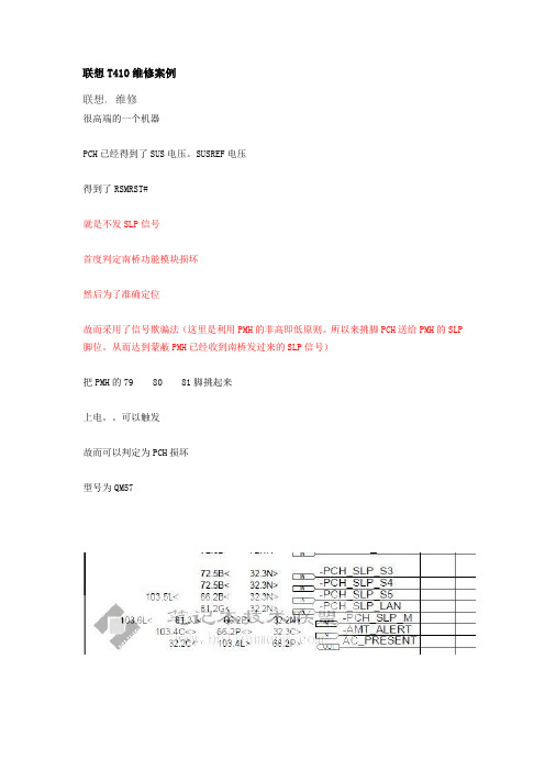
联想T410维修案例联想, 维修很高端的一个机器PCH已经得到了SUS电压。
SUSREF电压得到了RSMRST#就是不发SLP信号首度判定南桥功能模块损坏然后为了准确定位故而采用了信号欺骗法(这里是利用PMH的非高即低原则。
所以来挑脚PCH送给PMH的SLP 脚位。
从而达到蒙蔽PMH已经收到南桥发过来的SLP信号)把PMH的79 80 81脚挑起来上电。
可以触发故而可以判定为PCH损坏型号为QM57***************************************这里说下。
之前因为写案例没有看图纸。
对各位产生一定的误导。
不是上面提到的79 80 81的脚位前提修改的信号为:PCH送给PMH的SLP信号脚位各位自己去看下就可以了1评分人数o我不是专家: 看马哥的精品每次都能学到很多 ...威望 + 1本主题由 System 于 2010-9-4 05:00 撤销鉴定收藏分享•支持•反对需要积分的朋友请更多的关注联盟论坛的论坛任务和答题任务(在答题中您可以获得更多的技术理论知识)联盟高级班第十期实地笔记本维修培训招生中,暂定于2010年10月8日开课。
2#发表于 2010-8-25 16:34 | 只看该作者CPU可以支持I3 I5等CPU。
南北桥显卡集成回复引用报告使用道具 TOP3#发表于 2010-8-25 16:39 | 只看该作者留帖纪念:我在玩这个套路的时候,居然有才跟我10来天的人就看出了其中的奥妙绝。
接手公司带不成功的几个人带技术。
这么点时间就能看出我玩的套路,实在是进步神速。
《计算机组成原理》试卷A与参考答案
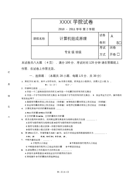
有一个64K×16位的存储器, 由16K×1位的DRAM芯片(芯片内是128×128结构)构成,存储器读/写周期为500ns。试问:
(1)(3分)需要多少DRAM芯片?
(2)(3分)采用异步刷新方式,如果单元刷新间隔不超过2ms,则刷新信号周期是多少?
(3)(3分)如果采用集中式刷新,存储器刷新一遍最少要用多少时间?
18.已知X为整数,且[X]补= 10011011,则X的十进制数值是。
A +155 B–101 C–155 D +101
19.主存储器是计算机系统的记忆设备,它主要用来。
A存放数据B存放程序C存放数据和程序D存放微程序
20.指令系统采用不同寻址方式的目的是。
A实现存贮程序和程序控制;B缩短指令长度,扩大寻址空间,提高编程灵活性; 。
C变址寄存器内容加上形式地址 (位移量)D程序记数器内容加上形式地址 (位移量)
4.计算机系统中的存贮器系统是指。
A RAM存贮器B ROM存贮器
C主存贮器D cache、主存贮器和外存贮器
5.若浮点数用补码表示,则判断运算结果是否为规格化数的方法是。
A阶符与数符相同为规格化数B阶符与数符相异为规格化数
A主存地址寄存器B程序计数器C指令寄存器D状态条件寄存器
16.微型计算机系统中 ,操作系统保存在硬盘上,其主存储器应该采用。
A RAM B ROM C RAM和ROM D CCP
17.至今为止,计算机中的所有信息仍以二进制方式表示的理由是。
A.节约元件;B运算速度快;C物理器件的性能决定 ;D信息处理方便;
XXXX学院试卷
2010-2011学年 第2学期
课程名称
计算机组成原理
vm17十六进制显卡代码
vm17十六进制显卡代码摘要:1.显卡代码背景介绍2.VM17十六进制显卡代码解析3.代码实战应用与演示4.总结与展望正文:一、显卡代码背景介绍在计算机图形学领域,显卡代码是指用于控制显卡硬件的一系列指令。
这些指令可以实现三维模型的渲染、二维图像的处理等各种图形效果。
VM17是一种十六进制显卡代码,广泛应用于各种显卡编程教程和实际项目中。
二、VM17十六进制显卡代码解析1.代码结构VM17代码主要由三部分组成:头部、指令集和数据段。
头部包含代码的版本信息、入口点等;指令集包含各种图形渲染和处理相关的指令;数据段用于存储渲染过程中的临时数据。
2.指令集详解VM17指令集包括以下几类:(1)渲染指令:用于控制三维模型的渲染,如光照、纹理映射等。
(2)矩阵指令:用于变换和矩阵操作,如模型视图矩阵、投影矩阵等。
(3)纹理指令:用于二维图像的处理,如滤波、混合等。
(4)状态指令:用于控制渲染状态,如启用或禁用某项功能。
(5)其他指令:如打包、解包等。
3.代码示例以下是一个简单的VM17代码示例:```VM17 beginversion "1.0"entrypoint "main"// 定义渲染状态state beginenable_blending(true)enable_texture(true)end// 定义模型矩阵matrix model_matrix = ...// 定义视图矩阵matrix view_matrix = ...// 定义投影矩阵matrix projection_matrix = ...// 渲染模型render_model(model_matrix, view_matrix, projection_matrix) // 处理二维图像process_texture(...)VM17 end```三、代码实战应用与演示1.显卡编程教程VM17十六进制显卡代码广泛应用于显卡编程教程,帮助学习者掌握显卡编程的基本知识和技巧。
ThinkPad T410 BIOS设置详解(图文并茂)

ThinkPad T410 BIOS设置详解(图文并茂)开机时按F1进入BIOS设置主菜单:一基本设置二时间和日期三密码及安全设置四启动选项五推出设置六硬盘诊断程序BIOS版本版本发布日期内嵌控制器版本机器型号机身序列号主板序列号固定资产信息处理器类型处理器速度已安装内存大小进入基本设置菜单:一网络二PCI三USB四键盘和鼠标五显示六电源管理七提示音和报警八内存九SATA控制器十处理器进入网络菜单:①网络唤醒【接AC时】注:当以太网控制器接收到远程唤醒数据包时,让系统开机。
注意,如果设置有硬盘密码,Wake On LAN 功能将不起作用。
(建议关闭)②BIOS网络更新【启用】注:使计算机的BIOS 能够通过活动的网络连接进行更新(刷新)。
(建议关闭)③载入LAN ROM 【启用】注:装入Ethernet LAN Option ROM 可以从集成的网络设备启动。
(以太网卡的一个特殊功能,默认即可)④磁盘高速缓存【启用】注:如果禁用了它,在网络引导中,硬盘驱动器的性能可能会降低。
⑤无线局域网和WiMAX 【开】注:无线局域网和WiMAX广播。
选择“On”,开启内部无线通信。
选择“Off”,关闭内部无线通信。
进入PCI菜单:这项中可以设置PCI的中断地址。
默认即可。
进入USB菜单:①USB输入输出系统支持【启用】注:启用或禁用USB 软盘驱动器和USB CD-ROM 的引导支持。
如果不启用USB,将无法使用任何USB界面之设备,例如:外置USB界面之软驱,光驱。
一般我们都要选择Enabled②持续USB供电【启用】注:如果您选择“Enabled”,那么在计算机连接到交流电源的情况下,外部USB 设备可在计算机处于低电源状态(睡眠/待机、休眠或电源关闭)时通过USB 端口进行充电。
③持续USB供电模式【自动选择】进入键盘和鼠标菜单:①指点杆开关【自动】②触摸板开关【自动】③Fn和Ctrl键互换【禁用】④Fn键锁定【禁用】注:按下FN键2次时,就可以不需要一直按住FN键,直接选择Fx 功能键。
- 1、下载文档前请自行甄别文档内容的完整性,平台不提供额外的编辑、内容补充、找答案等附加服务。
- 2、"仅部分预览"的文档,不可在线预览部分如存在完整性等问题,可反馈申请退款(可完整预览的文档不适用该条件!)。
- 3、如文档侵犯您的权益,请联系客服反馈,我们会尽快为您处理(人工客服工作时间:9:00-18:30)。
1 75
97 . 84
40
老板
西门子
1 3 5
1 47
1. 17
1 06
145 .6
155 .6
老板
西 门 子
1. 1 5
1 40
1 . 10
81
14 8 .9
18 7 .6
帅康
西 门 子
1 . 40
1. 11
87
65 .
175 .2
183 .3
海尔 帅康 华帝
小鸭
l 4 1 76 50
25
1. 62 71 . 47 .
59 .
73 9 129 ,0 119 .7
48 7
华帝 帅康 美的
红日
1 04 82 76 .
樱花
康赛特 华 帝
44 .
39 37 .
31 .
80 20
12 2 . 2
46 1 15 7 ,4
帅康
康 赛 特
39
22 .
19
73 .
163 .6
24 5
万喜
35 .
65
57 7
哈 尔 滨
次
沈 m I
方 太 华 帝
2 1 年 4月 1 00 6大城 市燃 气灶 前 1 0名市场 占有率 ( )及均价 ( ) % 元
上 海
■罄睡 ■啊—疆醇孽品— 越■■■ 踊
老板
西 门子 方 太
1 88
1 . 82 1 53
1 9 2
1 1 6 1 01
192 .7
212 .2 20 3 .5
德意 美的
康 宝
94 93 .
75 .
62 . 1 6 7
1 09
12 7 .8 49 4
56 8
帅康 德意 樱花 美的 华帝
万 家 乐 康 宝
90 . 88 49 . 49 37
27 1 8
75 . 96 . 50 . 85 48 .
189 .8
帅康
华 帝
1 . 04
73
79 .
71
170 .7
130 .9
华 帝 美的
万和
93 85
74
1 07 1 . 09
1 . 5 3
帅康
华 帝
53
44 .
38
36
127 . 4
101 .8
樱 花
能率
海 尔 康 宝
55 .
30 . 1 5
62 .
39 . 39 .
120 .o
105 .3 5 1 5
海尔 万家乐 德 意
42 31 27
47 . 69 23
华帝 樱花
万 和
52 47
41
54 . 40
60 59
182 .4 149 .2 159 .3 80 9 111 .7
73 0 45 8
帅康 美的
西 门子
67 . 64 .
55 .
53 . 78
30
132 .2 87 6
’86 .9
老板
樱 雪
85
64 .
43
1 1 7 ’ . 54
89 1 . 35
204 6 123 .2
华 帝
1 2 9
1 . 73
方 太
3 00
1. 6 7
1 9 .1 9
方 太
1 72
1 1 1
16 7 7
前锋
美的 年代
方 太
1 . 9 3
88 87 .
林 内
59 .
58
71 .
1 03
115 .2
75 5
德 意 美 的
60 . 53
55 . 68
14 .“ 10 0 .4
厨 之 宝 万 家 乐 海 尔
44 . 42 . 39
80 52 37
47 8 76 0 95 3
81 .
166 .1
60 5
老板
火王
74 .
46
36
40
1 77 . 3
92 6
美的
康 宝
54
51 .
71
96
60 3
43 3
海 尔
海标
红 日
49 .
37 .
3 7
54
82
48
90 6
40 8
8 1 5
华 帝
1 . 5 7
1 06
131 6
西 门 子
2 31
1 9 5
225 .4
华帝 老板
方太
2 60 1. 81
1 1 3
2 56 1 . 40
71
101 .7 131 .6
160 .7
方 太
万 和
1 7 71 01帅康 方太 老板 西 门子
1 5 7 1 . 53 1 2 2
1 1 1
1 1 1 1 . 03 78
66
方 太
1 82
1 . 02
158 。 7
方太 老板 帅康
西 门 子
光 芒
1. 44 1. 34 1 1 5
1. 08
1. 0g
96 . 95 . 87
71 .
1 4 1
202 .0 181 .8 179 .6
209 .3
12 8 .2
老板 美的
西门子
1. 41 1 09
87 .
89 . 1 6 3
41 .
141 .1 72 1
80 .
13 7 .0 15 0 .5
69 8
樱花
34
24 .
1 8 2 9
广 州
■ ■■ B _ ■鹜略 ■■■鳃I 瞄强■- 酱_ 螫 硐 ■ ■_
天津
_翳 鬈蝴哪 酩 胡菌 - - 露l 嫡 ■ 鼎■ ■■ ■冒墨誊 萄_ 峭 I 瞩目量■I 蕾 ■■ ■ 舸
66
1 20
224 .8
78 1
西 门 子 万 和 方 太
1 . 12 92 89 .
54 1 . 39 36 .
178 。2 58 4 205 ,2
老板
方 太
2 02
1 68
1 80
1 30
179 .2
202 .0
49
