Concept_C中文手册
CONCEPT 80 简单操作说明
一、宽带介电谱测量系统的组成实验室选用的测量系统包括低频模块和高频模块两大部分。
其中低频模块为Alpha-A高性能频率分析仪(Alpha-A High Performance Frequency Analyzer);高频模块为安捷伦E4991A射频阻抗/材料分析仪(Agilent E4991A RF Impedance/Material Analyzer)。
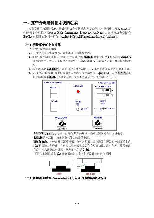
(一)测量系统的上电操作下图为电源模块面板图1、上推合上墙上电源开关,合上地面上接线盒电源。
2、合上电源控制面板上右下侧的主控制器电源MAINS(由0位打至1位),启动Alpha-A高性能频率分析仪。
校准和测量都应当在系统启动30分钟后再进行,保证预热的效果。
3、真空泵电源V ACUUM在需要进行温度控制时打开,不需要进行温度控制时不打开。
4、在进行温度控制时合上电源面板左侧的温度控制系统(QUATRO)电源MAINS和加热器电源LOAD,这两个电源开关在不需要进行温度控制时不打开。
MAINS(下)是总电源,内部有10A的熔丝,当发生短路时自动切断电源。
LOAD是杜瓦罐中加热器和气体加热器的电源。
面板保险座:当外部杜瓦罐蒸发器、气体加热器、或电缆发生短路时控制面板上的20A断路器工作弹出,此时应该检查设备是否存在短路故障,进行修理。
故障处理完后,推入断路熔丝开关,熔丝的电阻是2~3Ω。
下图为电源面板上20A断路器正常工作时和短路跳出时的位置图:(二)低频测量模块 Novocntrol -Alpha-A高性能频率分析仪低频模块的主主框架(Mainframe)分析仪为Alpha-A高性能频率分析仪(Alpha-A High performance Frequency Analyzer),配接的是ZGS接口试样单元。
分析仪主框架部分内含正弦波信号源和直流偏置电源、2个电压通道。
上电后,分析仪自动检测端口连接的试样单元,并调整相应的系统功能。
1 Alpha-A分析仪Alpha-A主框架部分的界面图:Gen :为内置在测试接口的信号输出放大器提供一个交流输出信号,在进行增益相位测量时作为信号源。
CONCEPT 201 C 用户手册说明书

CONCEPT 201 CUSER’S MANUALCONCEPT 201 C TABLE OF CONTENTS MACHINE DESCRIPTION:Manufacturer’s address: (3)Range of application: (3)Maximum capacity of the unit: (3)Principle description: (3)Safety Warnings: (4)PRE INSTALATION:Technical datas : (5)Crate dimension: (5)Floor space requirement: (5)Connections location : (6)Accessories needed for the connections: (6)INSTALLATIONUnpacking: (7)Parts delivered with the machine : (8)Connections: (9)USER'S MANUAL:Initial operation of the machine: (10)Machine configuration: (11)Value modification: (12)Section selection: (13)Plate data memorisation: (14)Process visualisation: (17)Start a Washout cycle: (18)Start an Exposure cycle: (18)Start a Drying cycle: (19)Dryer automatic switch off: (19)Start a Post-Exposure / Light Finishing cycle: (20)Alarms: (21)Edition AA, May 2010This book has part No. 10068538Manufacturer’s address:DEGRAF S.p.A."Il Girasole" - Palazzo Donatello 8/03b20084 Lacchiarella (MI)ItalyRange of application:This unit is a part of a full range dedicated for the treatment of flexographic printing plates. This range includes Exposure, Processor, Dryer and light finisher.The unit is designed for the exposure, the washout, the drying as well as the post exposure and light finishing of solvent washable printing plates.Maximum capacity of the unit:Warning:This unit is designed to work with solvent and has been tested with conventional product. Always ask your dealer before trying to change the type of solvent. This may result in major damages and safety issues. This machine has not been designed as an explosion proof unit.Principle description:•This unit is designed to expose, wash, clean, dry, post expose and light finish printing plates.•The machine is divided in major sectionso Control panel: allow the operator to select the correct parameters to process the plates.o Washout section: designed to provide high quality and even washout of the plates as well as high performance cleaning.o Exposure section : 18 lamps of 60W to ensure even exposureo Dryer section: 4 drawers. 2x 800W heating resistors.o Post exposure /light finishing section: 12 UVA lamps (60W) and 11 UVC lamps(75 W).•The operator interface is made touch screen which ensures a very easy interface.Safety Warnings:Technical datas :Crate dimension:•Please ensure the handling of the cratewill be compatible with the buildingconfiguration: doors dimensions, loadcapacity of the floor …Floor space requirement:•Please ensure there will be sufficient space around the machine for safe use as well as easy access for maintenance. 1 meter free space is needed in front of the machine to give an easy access. On the sides and the back of the unit 500 mm are requested to allow the access.Connections location : • All the connection points are located on the back of the unit.Accessories needed for the connections:Upon receipt of your machine please check with the carrier the status of the crate. Notify him of any damage you see on the crate.Before starting to unpack the unit, make sure you have all required tools ready to hand. Unpacking:Warning: For safety reasons, please wear appropriate protective clothing (gloves, glasses, and safety shoes) while unpacking.•Start by removing the top section of the crate.•Remove the sides one by one.•The machine is now resting on the base of the crate.•Remove all blocking pieces of wood.•Use the appropriate forklift to lift the unit and get it to its installation location. Take care that the forks are long enough to lift the machine without causing damage.•Ensure there is sufficient space around the machine (see Pre-installation section).•Remove all protection from the unit (do not use sharp tools to prevent damages).•No special anchorage is needed for this unit. The unit will rest only on its feet.•Align the machine precisely by means of a water gauge. The alignment is made by using the adjustable feet.Parts delivered with the machine :Verify that all parts are with the machine.Connections:All the needed connections have to be made in accordance with the rules of the installation country.Electrical connection :•Connection such as electrical power supply has to be made by certified people.•It is recommended to use a ground fault circuit breaker as well as a lockout type power switch for the electrical connection.•Before switching on the machine, ensure that the voltage measured on the main switch of the machine match the identification plate fixed on the back of the unit. Exhaust blower connection:•Connect all the exhaust, except the exposure exhaust which may blow into the room, to the appropriate location (directly to the outside or to the building exhaust installation). Ensure the airflow is correct.Compressed air connection:•Connect the compressed air line to the unit.Solvent connection:•Connect the solvent lines to the correct points.•Connect the solvent level sensors (high level used solvent and low level fresh solvent) in the correct plugs.Filling the heater/cooler tank:•Remove the panel located on the left side of the unit.•Remove the cover of the heater/cooler tank.•Prepare 4 litters of a solution based on 70% of de-mineralized water (or distilled water), 30% of ethylene glycol and some drops of algaecide (anti-foam action).•Fill the tank to the maximum.•After running the unit for a couple of minutes, it may be needed to check again the level of the heater/cooler tank and to add solution to reach the correct level.Note: This operation has to be made with the machine switched OFF.Initial operation of the machine:Before switching the machine on make sure that the working area around the machine is clean and free for easy movement.Check if there are any leaks of solvent as well as all the needed supplies:✓Electrical power supply: cable connected and not damaged.✓Compressed air: filter clean and pressure correct.✓Exhaust: hose connected and not damaged.•You are now ready to switch the machine on.•the machine (right-hand side).•Verify, that all emergency stop buttons are released. If not, releasethem by turning them clockwise.•Switch the machine on by pressing the ON/OFF button which islocated beneath the control panel of the machine.•displayed on the touch screen:The machine has been stopped with at least1 plate in process in the processor section.Keep pressing “RESET UNIT” for a few seconds toreset all the on going cycle.Keep pressing “RESTART UNIT” for a fewseconds to restart the processor at exactly thesame status of the power switch OFF. This allowsto continue the process of a plate remaining insidethe processor.NOTE: All the other process carried on at the switch OFF of the unit will be reseted in both case. It is only possible to restart the processor cycle.The machine is ready to be used.Machine configuration:For access to the machine set -up, press the designated key.The machine configuration screen allows you to set the machine:The machine configuration screen allows you to modify:in theManual: UVA and UVC can be started separately or all together.Automatic: UVA and UVC will be made one after the other in a sequence depending ofthe first one started.Value modification:•To change a value (numeric or alpha numeric) directly press the desired value and the corresponding keypad will appear.Alpha numeric keypad: Numeric keypad:•Enter the new value and then confirm by pressing .•To close the keypad, press.•If the entered value is out of range of the data it will return automatically to the minimum or maximum range limit. Note: these range limits are different for the same data depending on the setup of the machine.The data are automatically stored in memory as soon as the key is pressed.Section selection:It is possible to change from one section to another one simply by pressing on the section desired on the right of the screen. The activated section is shown in black.Washout section selected. Exposure section selected.Ligth finisher section selected. Dryer section selected.Plate data memorisation:20 memory channels are available to store the plate data.To switch from one channel to another simply press or . The memorised data are then displayed. It is possible to memorise the plate parameters for the Processor section, the exposure section as well as the Light finisher section. The drying time of the dryer section are memorised but not linked to any memorised plate channel.Exposure section:Press this zone to enter the plate type with thealpha numeric keypad.Note: The plate name is the same for all sectionsfor the same memorisation channel.Press on this zone to enter the back exposuretime with the numeric keypad.Press on this zone to enter the main exposuretime with the numeric keypad.Processor section:Press this zone to enter the plate type with thealpha numeric keypad.Note: The plate name is the same for all sectionsfor the same memorisation channel.Press this zone to enter the washout time with thenumeric keypad.Press this zone to enter the relief expected on theplate (used only for the replenishment calculationwhen the solid content measurement device is notactivated).Press this zone to enter the plate size (in mm orinches depending on the machine configuration).The selection is made by step of 25% of themaximum size. Every press on the touchincrements the plate size from 25 to 50 to 75 to100% and then back to 25 (used only for thereplenishment calculation when the solid contentmeasurement device is not activated).Dryer section:Press on the desired time to enter the drying timeof the corresponding dryer drawer.Light Finisher:Press on this zone to enter the Post exposure time(UVA lamps).Press on this zone to enter the Light Finishingtime (UVC lamps).Process visualisation:•During a cycle, it is possible to see whichfunction is On or OFF in the machine. Simplypress on the dedicated touch to access to thevisualisation screens.•All functions running are coloured in black.•First select the required program by using thekeys or .•Verify, that all parameters are correct.•Open the entrance cover.•Fix the plate on the transport table and ensurethe plate is well fixed. It is not possible to havethe plate well fixed if the sticking material is stillwet.•Close the entrance cover.•To start the cycle, press .Note: During the Washout process it is possible to seethe remaining time on the right part of the screen. Note: It is required to wait between two plates the sticky material is well dry to ensure a good fixation of the plate.WARNING: In case the sticky plate holder is not completely covered with the plate(s)to process, the non covered area must be protected with the cover sheet of flexo plate (for example) to prevent long contact between the sticky material and the solvent. Not doing this may result in very short life time of the sticky material.Start an Exposure cycle:•keys or .•Verify that all parameters are correct.•Open the Exposure drawer.••for digital plates).•exposure cycle has been started.•Close the drawer.•To start the cycle, press“START MAIN”.Note: During an Exposure processit is possible to see the remainingtime on the right part of thescreen.•Be sure the dryer is ON ((top left corner touchON/OFF)•Verify that the drying time is correct.•Open the Dryer drawer.•Put the plate in the drawer.•Close the drawer.•Press the “START” touch correponding to thedesired drawer.Note:Note: During the Washoutprocess it is possible to see theremaining time on the right part ofthe screen.Dryer automatic switch off:While having drying times on going, simply press on the touch ON/OFF dryer (top left corner)to switch off the dryer. The display of the remaining times will then display alternatively the times and “A-S” to indicate the dryer in automatic switch off mode. At the end of all drying times, the heating resistors and then the blowers switch off automatically.To cancel the automatic switch off mode, simply restart the dryer using the top left touch.Start a Post-Exposure / Light Finishing cycle:•First select the required program by using thekeys or .•Verify that all parameters are correct.•Put the plate in the Light finisher drawer.•To start the cycle, press“START UVA” or“START UVC”.NoteNote: During an Exposureremaining time on the right part ofthe screen.Specific cycle:The unit offers the possibility to have an automatic sequence of Post exposure and Light Finishing.•Sequence exposures:If this function has been enabled (refer to “Machine Configuration” section) the cycle is proceeding as followed:If « START UVA » is pressed : the UVA lamps start until the end of the selected time, and after a time delay, the UVC lamps start until the end of the selected time.If « START UVC » is pressed : the UVC lamps start until the end of the selected time, and after a time delay, the UVA lamps start until the end of the selected time.Alarms:•on.•• A graphic alarm signal indicates the type ofalarm (refer to following examples):o Level problem of the different solvent tanks. The warning signal is blinking near the corresponding level indication.o Excess temperature (of solvent or water). The warning signal is blinking near the solvent or water temperature indication.o Problem on a circuit breaker for the pumps and motors. The warning signal is blinking near the malfunctioning motor, pump or circuit breaker.Eng. version AA: 30/05/2010. Correction of solvent hose diameter 20->16mm. Eng. version V1.1: 27/08/2008. Add automatic switch of the dryer.。
用户手册-Concept 功能块

3.1 CLC 组 ........................................................................................ 28 3.1.1 DELAY【延时】 ................................................................................................................................................. 28 3.1.2 INTEGRATOR1【带输出限幅的积分器】........................................................................................................ 30 3.1.3 LAG1【一阶滞后滤波器】 ................................................................................................................................ 32 3.1.4 LEAD_KAG1【带滞后时间的 PD 组件】 ........................................................................................................ 33 3.1.5 LIMV【一阶速度限制器】 ................................................................................................................................ 36 3.1.6 PI1【PI 调节器】 ................................................................................................................................................ 38 3.1.7 PID1【PID 调节器】 .......................................................................................................................................... 41 3.1.8 PIDP1【并行结构的 PID 调节器】.................................................................................................................... 46 3.1.9 SMOOTH_RATE【带延时的微分器】.............................................................................................................. 51 3.1.10 THREEPOINT_CON1【三点调节器】 ......................................................................................................... 52 3.1.11 THREE_STEP_CON1【三位步进调节器】.................................................................................................. 55 3.1.12 TWOPOINT_CON1【两位调节器】............................................................................................................. 57
实操concept教程
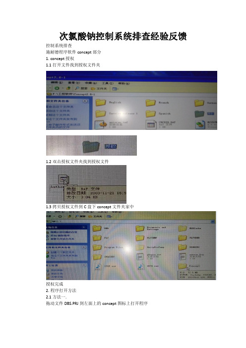
次氯酸钠控制系统排查经验反馈控制系统排查
施耐德程序软件concept部分
1.concept授权
1.1打开文件找到授权文件夹
1.2双击授权文件夹找到授权文件
1.3拷贝授权文件到C盘下concept文件夹家中
授权完成
2.程序打开方法
2.1方法一.
拖动文件DBS.PRJ到左面上的concept图标上打开程序
2.2方法二
双击桌面图标打开文件找到DBS.PRJ程序文件与WORD打开文件一样的方式,不在详情介绍。
3.concept主界面面介绍
3.1打开循环水次氯酸钠文件下
项目名称
编程方式LL984
程序块
3.2查找程序变量的方法
查找变量类型在以下文件中查找类型
输入变量名
称
3.3运行空CPU方法
单击
单击改变控制状态
3.4 PLC框架配置
双击
双击
双击
配置模块
输入模块对应地
址
输出模块对应
的地址
3.5变量强制
单击
3强制变量
1输入变量2输入变量值。
concept驱动器中文手册
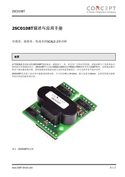
2SC0108T描述与应用手册双通道、超紧凑、低成本的SCALE-2驱动核摘要新型SCALE-2双驱动核2SC0108T集低成本、超紧凑于一身,而且有广泛的应用范围。
该驱动器专门为要求高可靠性的应用领域而设计。
2SC0108T可以驱动600A/1200V或者450A/1700V的所有常见IGBT模块。
这款驱动器支持多个驱动器直接并联,使其能够很容易地实现大功率的逆变器设计,并可支持多电平拓扑应用。
2SC0108T是目前工业应用中最紧凑的驱动核,尺寸仅有45 x 34.3mm,最大高度为16mm。
这使其即使在最狭窄的空间也仍能有效应用。
图 1 2SC0108T驱动核目录摘要 (1)目录 (2)驱动器概述 (4)机械尺寸(2SC0108T2Ax-17、2SC0108T2Bx-17和2SC0108T2Ex-17) (5)机械尺寸(2SC0108T2Cx-17和2SC0108T2Fx-17) (6)管脚定义 (7)原方接口的推荐电路 (8)原方接口电路描述 (8)概述 (8)VCC端子 (8)MOD(模式选择) (9)INA、INB(驱动输入端,例如PWM信号) (10)SO1、SO2(状态输出) (10)TB(阻断时间T b设定端) (10)副方接口的推荐电路 (11)副方接口电路描述 (11)概述 (11)发射极端子(VEx) (11)参考端子(REFx) (12)使用电阻的集电极电位检测(VCEx) (12)使用二极管检测IGBT退饱和进行短路保护 (13)屏蔽V ce,sat检测 (15)门极开通(GHx)和门极关断(GLx)端子 (15)有源箝位 (16)2SC0108T SCALE-2驱动器的详细工作原理 (16)电源及电气隔离 (16)电源监控 (17)2SC0108T并联 (17)三电平或多电平拓扑 (17)2SC0108T的附加应用支持 (17)参考文献 (17)信息源:SCALE-2驱动器数据手册 (18)特殊要求:定制SCALE-2驱动器 (18)技术支持 (18)质量 (18)法律免责声明 (18)订购信息 (19)其他产品的信息 (19)生产厂商 (19)驱动器概述2SC0108T装备了CONCEPT公司最新的SCALE-2芯片组/1/,是一款低成本的驱动核。
CONCEPT 205 C 预装载手册说明书

Pre-installation Manual - CONCEPT 205 C
1416
Introduction 0-3
Part 0: Introduction
Reservations
• This manual was written and illustrated using the best possible information available at the time of publication.
Part 1: Transportation . . . . . . . . . . . . . . . . . . . . . . . . . . . . . . . . . . 1-1
When the unit arrives . . . . . . . . . . . . . . . . . . . . . . . . . . . . . . . . . . . . . . . . . . . . . . 1-1 Storing the unit before installation . . . . . . . . . . . . . . . . . . . . . . . . . . . . . . . . . . . 1-1
• Any differences between this manual and the equipment reflect improvements introduced after the publication of the manual.
• Changes, technical inaccuracies and typographic errors will be corrected in subsequent editions.
CONCEPT_1SP0635_Manual_2012-02-28_CN_中文说明书
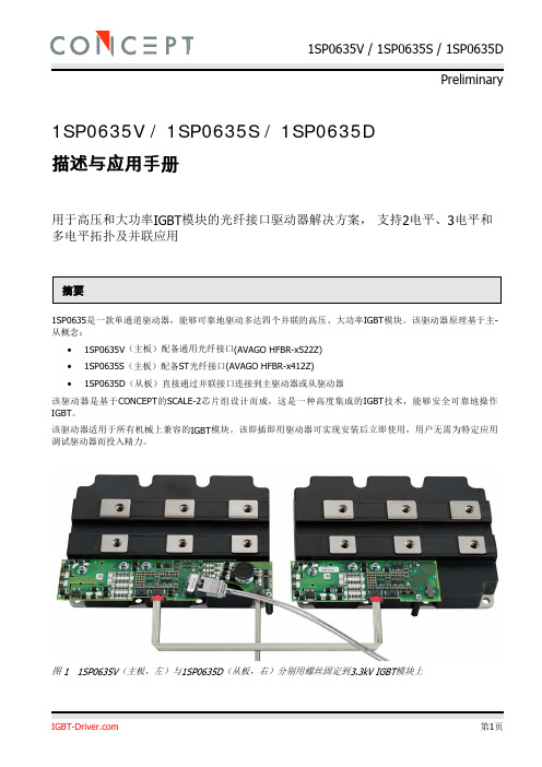
1SP0635V / 1SP0635S / 1SP0635D描述与应用手册用于高压和大功率IGBT模块的光纤接口驱动器解决方案,支持2电平、3电平和多电平拓扑及并联应用摘要1SP0635是一款单通道驱动器,能够可靠地驱动多达四个并联的高压、大功率IGBT模块。
该驱动器原理基于主-从概念:∙1SP0635V(主板)配备通用光纤接口(AVAGO HFBR-x522Z)∙1SP0635S(主板)配备ST光纤接口(AVAGO HFBR-x412Z)∙1SP0635D(从板)直接通过并联接口连接到主驱动器或从驱动器该驱动器是基于CONCEPT的SCALE-2芯片组设计而成,这是一种高度集成的IGBT技术,能够安全可靠地操作IGBT。
该驱动器适用于所有机械上兼容的IGBT模块。
该即插即用驱动器可实现安装后立即使用,用户无需为特定应用调试驱动器而投入精力。
图 1 1SP0635V(主板,左)与1SP0635D(从板,右)分别用螺丝固定到3.3kV IGBT模块上目录系统概述 (4)1. 1SP0635V/1SP0635S(主板) (4)2. 1SP0635D(从板) (5)3.使用主-从驱动器进行IGBT模块并联 (6)使用方法 (6)1. 选择合适的驱动器 (6)2. 将驱动器安装到IGBT模块上(每个IGBT一个驱动器) (7)3. 将驱动器连接到控制单元 (7)4. 检查驱动器功能 (7)5. 设置和测试功率单元 (7)机械尺寸 (8)1. 1SP0635V(主板) (8)2. 1SP0635S(主板) (8)3. 1SP0635D(从板) (9)推荐的电缆和PCB连接器 (9)连接器X1的管脚定义(1SP0635V/1SP0635S的电源) (10)接口X1的描述(1SP0635V/1SP0635S的电源) (10)光纤输入描述(1SP0635V/1SP0635S) (10)光纤输出描述(1SP0635V/1SP0635S) (10)光纤的推荐接口电路(1SP0635V/1SP0635S) (12)并联接口X2和X3描述 (13)LED状态指示灯 (14)1SP0635V和1SP0635S SCALE-2驱动器的工作原理(主板) (14)概述 (14)电源及电气隔离 (14)电源监控 (14)V ce检测/短路保护 (15)门极监控 (15)1SP0635D驱动器的工作原理(从) (16)概述 (16)电源及电气隔离 (16)电源监控 (16)V ce检测/短路保护 (17)门极监控 (17)使用1SP0635V/1SP0635S/1SP0635D时的注意事项 (17)通过1SP0635驱动器并联IGBT模块 (17)IGBT的动态行为 (19)IGBT开通/二极管换流 (19)IGBT关断 (19)动态高级有源钳位DA2C (19)低杂散电感结构要求 (21)三电平和多电平拓扑 (21)牵引或类似应用的更高要求 (21)参考文献 (22)信息源:SCALE-2驱动器数据手册 (23)特殊要求:定制SCALE-2驱动器 (23)技术支持 (23)质量 (23)法律免责声明 (23)订购信息 (24)其他产品的信息 (24)生产厂商 (24)系统概述1SP0635是由CONCEPT 开发的基于高度集成的SCALE-2芯片组的即插即用驱动器/1/。
Concept使用说明

Concept使用说明一、安装软件及授权1、打开concept文件,先安装“cc26”再安装“sr5”,安装完成后直接把授权文件复制到安装的路径中去即可,点击替换所有。
二、新建项目1、打开软件:点击开始——程序——concept V2.6 XL——concept,如下图所示。
页脚内容1打开软件界面后如下图所示。
页脚内容22、新建项目:点击File——Open进入新建项目的弹窗。
为新项目命名,选择其保存路径,如下图所示。
选择好后点击确认即可页脚内容33、配置PLC:确认完毕后会弹出PLC配置窗口,如下图所示双击PLC Selection(PLC选择),弹出PLC选择窗口,开始选择所用的CPU型号,如下图所示。
型号选择完毕后点击OK即可页脚内容4CPU选择完毕后可以开始配置其它模块,点击配置中左侧的I/O Map ,弹出如下窗口点击弹窗右侧Edt 下面的按钮,弹出配置其它模块的窗口,如下图所示页脚内容5点击弹窗中“Module”下面的按钮,选择相应的模块。
然后点击“in ref”或者“out ref”下方的空格,输入模块地址分配的起点。
3xxxxx 用于模拟输入模块,4xxxxx 用于模拟输出模块,3xxxxx 或1xxxxx 用于数字输入模块,4xxxxx 或0xxxxx 用于数字输出模块,1xxxxx 或3xxxxx 用于专家模块( 输入),0xxxxx 或4xxxxx 用于专家模块( 输出)具体情况如下图所示例子。
页脚内容6模块配置完毕后点击OK即可设置通讯:首先需要配置一个以太网模块,在I/OMap中按上图所示的把模块配置成功。
然后双击Selec extensions,弹出以下窗口,将其中右侧的TCP/IP Ethemet设置为1(注,先要设定这个,再才能在配置模块中找到相应的以太网模块)页脚内容7设置为1后点击确定会生成一个选项“Ethemet/I/O Scanner”双击此按钮,弹出以太网配置配置的窗口,然后在其中添加相应的IP地址即可。
CONCEPT_2SC0435T_Manual_2013-02-21_CN
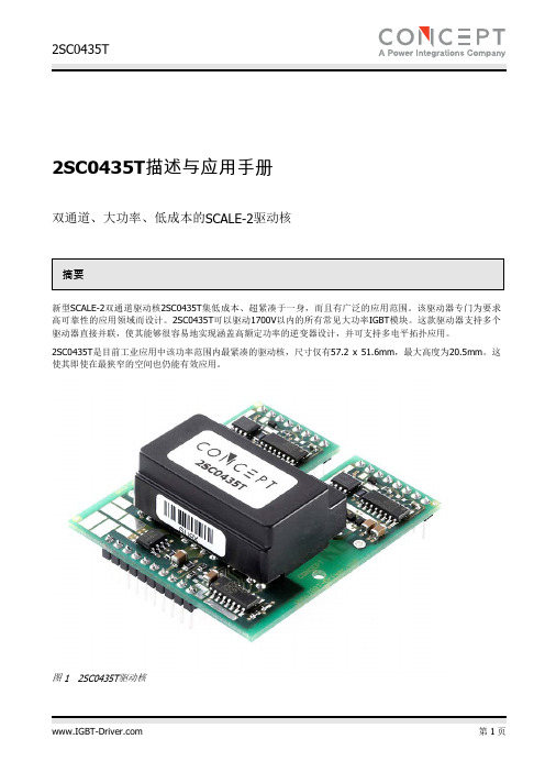
概述 .................................................................................................................................... 12 DC/DC 输出(VISOx)、发射极(VEx)和 COMx 端子 .................................................................... 12 参考端子(REFx) ................................................................................................................... 12 集电极电位检测端子(VCEx) .................................................................................................. 12 有源箝位(ACLx) ................................................................................................................... 13 门极开通(GHx)和门极关断(GLx)端子 ..................................................................................... 14
概述 ...................................................................................................................................... 8 VCC 端子 ............................................................................................................................... 8 VDC 端子 ............................................................................................................................... 9 MOD(模式选择) ................................................................................................................. 9 INA、INB(驱动输入端,例如 PWM 信号) ........................................................................... 10 SO1、SO2(状态输出) ....................................................................................................... 10 TB(阻断时间 Tb 设定端) .................................................................................................... 10
CEF 使用说明中文版
这是一个翻译文档,持续更新中CEF General Usage(CEF3预览)介绍CEF全称Chromium Embedded Framework,是一个基于Google Chromium 的开源项目。
Google Chromium项目主要是为Google Chrome应用开发的,而CEF的目标则是为第三方应用提供可嵌入浏览器支持。
CEF隔离底层Chromium和Blink的复杂代码,并提供一套产品级稳定的API,发布跟踪具体Chromium版本的分支,以及二进制包。
CEF的大部分特性都提供了丰富的默认实现,让使用者做尽量少的定制即可满足需求。
在本文发布的时候,世界上已经有很多公司和机构采用CEF,CEF的安装量超过了100万。
[CEF wikipedia]页面上有使用CEF 的公司和机构的不完全的列表。
CEF的典型应用场景包括:嵌入一个兼容HTML5的浏览器控件到一个已经存在的本地应用。
创建一个轻量化的壳浏览器,用以托管主要用Web技术开发的应用。
有些应用有独立的绘制框架,使用CEF对Web内容做离线渲染。
使用CEF做自动化Web测试。
CEF3是基于Chomuim Content API多进程构架的下一代CEF,拥有下列优势:改进的性能和稳定性(JavaScript和插件在一个独立的进程内执行)。
支持Retina显示器。
支持WebGL和3D CSS的GPU加速。
类似WebRTC和语音输入这样的前卫特性。
通过DevTools远程调试协议以及ChromeDriver2提供更好的自动化UI测试。
更快获得当前以及未来的Web特性和标准的能力。
本文档介绍CEF3开发中涉及到的一般概念。
开始使用二进制包从源码编译(Building from Source Code)示例应用程序(Sample Application)重要概念(Important Concepts)C++ 封装(C++ Wrapper)进程(Processes)线程(Threads)引用计数(Reference Counting)字符串(Strings)命令行参数(Command Line Arguments)应用程序布局(Application Layout)应用程序结构(Application Structure)Windows操作系统(Windows)Linux操作系统(Linux)Mac X平台(Mac OS X)单一执行体(Single Executable)分离子进程执行体(Separate Sub-Process Executable)集成消息循环(Message Loop Integration)CefSettingsCefBrowser和CefFrameCefAppCefClientBrowser生命周期(Browser Life Span)离屏渲染(Off-Screen Rendering)投递任务(Posting Tasks)进程间通信(Inter-Process Communication (IPC))处理启动消息(Process Startup Messages)处理运行时消息(Process Runtime Messages)异步JavaScript绑定(Asynchronous JavaScript Bindings)通用消息转发(Generic Message Router)自定义实现(Custom Implementation)同步请求(Synchronous Requests)网络层(Network Layer)自定义请求(Custom Requests)浏览器无关请求(Browser-Independent Requests)请求响应(Request Handling)Scheme响应(Scheme Handler)请求拦截(Request Interception)其他回调(Other Callbacks)Proxy Resolution使用二进制包CEF3的二进制包可以在这个页面下载。
施耐德Concept技术应用

施耐德 Co ncept技术应用1.关于编程软件Conce ptXS,Conc eptS,Conc eptM,Conc eptXL主要区别。
Conc eptXS和Conc eptS只能对Mo mentu m PLC进行编程,无Con ceptSecur ity。
Conce ptM 可对Com pact和Mome ntumPLC进行编程,无C oncep t Sec urity。
Con ceptX L可对Qu antum、Comp act、M oment um、At rium进行编程,有Conce ptSe curit y。
2.Conc ept S和Con ceptM有多用户版吗?对于Conc ept软件而言,只有XL版才有单用户和多用户版,而Conce pt S和Conc ept M只有单用户版,没有多用户版,所以如果用户需要3个Conce pt M的拷贝的话,那么用户必须定3套C oncep t M的单用户版。
3.在C oncep t2.2SR2做I/O ma p时,找不到Quan tum A s-i模板140EI A92100,此模板有可能应用于Conc ept2.2 SR2下吗?Qu antum As-i模板能配置在本地机架,RIO分站,DIO分站上吗? Con cept2.2 SR2不支持A s-i模板140EI A92100,必须是Conce pt v2.5,Mo dsoft v2.61,Pro worxNxt v2.1支持此模板。
此模板可配置在本地机架,RIO分站,DIO 分站上。
本地机架最多可配4个E IA92100,RI O分站最多可配4个E IA92100,DI O 分站最多可配2个E IA92100。
main concept codec suite使用方法

main concept codec suite使用方法首先,要理解MainConcept Codec Suite的使用方法,需要了解它是什么以及它能做什么。
MainConcept Codec Suite是一套专业的视频和音频编解码器工具,用于处理和转换各种不同格式的媒体文件。
它提供了高质量的编解码功能,可用于视频编辑、媒体转码、流媒体媒体服务等应用领域。
以下是MainConcept Codec Suite的使用方法的一般步骤:1.安装:将MainConcept Codec Suite安装到计算机上,并确保遵循安装指南和系统要求进行正确的安装。
2.配置:根据需要,对MainConcept Codec Suite进行配置。
您可以使用软件的配置面板来选择合适的输出格式、编码设置、分辨率、比特率等。
确保按照底层工作流程和设备要求进行正确的配置。
3.导入媒体文件:将您要处理的媒体文件导入到MainConcept Codec Suite的工作区。
可以通过单击软件界面上的“导入”按钮或拖放文件到工作区来实现。
4.选择编码器:根据您的需求选择合适的编码器。
MainConcept Codec Suite提供了各种编码器,如H.264、MPEG-2、AAC等。
选择适当的编码器可以根据您的需求平衡视频质量和文件大小。
5.编辑和转码:如果需要,您可以对媒体文件进行编辑或应用其他处理效果。
MainConcept Codec Suite提供一些基本的编辑功能,如剪切、调整音量等。
然后,您可以选择转码媒体文件,将其保存为所需的格式和编码设置。
在转码过程中,您可以选择目标文件夹、文件名和其他设置。
6.导出输出文件:当您完成编辑和转码后,可以导出生成的输出文件。
MainConcept Codec Suite提供了多种输出选项,可以选择输出为文件、流媒体服务器、光盘等。
根据您的需求,选择适当的输出选项,并提供必要的参数和设置。
总的来说,MainConcept Codec Suite的使用方法涉及安装软件、进行配置、导入媒体文件、选择适当的编码器、编辑和转码文件,并最后导出输出文件。
concept c++ 语法
concept c++ 语法C++17引入了概念(concepts)这一特性,它是一种类型系统元编程的方式,可以用来约束模板参数的类型。
通过使用概念,可以更加清晰地表达模板的约束,使得代码更加简洁和易于理解。
下面是C++中概念语法的一些基本元素:1. 概念的定义:使用关键字concept来定义概念,后面跟着概念的名称和参数列表。
例如:cpp复制代码concept MyConcept = /* 约束条件*/;其中,/* 约束条件*/是一个逻辑表达式,用于定义概念的约束。
2. 概念的使用:在模板参数列表中使用概念来约束模板参数的类型。
例如:cpp复制代码template <MyConcept T>void foo(T t);在这个例子中,foo函数接受一个类型为T的参数,其中T必须满足MyConcept概念的所有约束。
3. 概念定义的语法:概念定义的语法通常使用逻辑运算符和类型系统元编程操作符来表达约束条件。
例如:cpp复制代码concept MyContainer = requires(T& c) {typename T::value_type; // T必须是一个容器类型,具有value_type成员类型{ c.begin() } -> typename T::iterator; // c必须有一个名为begin()的成员函数,返回一个迭代器类型{ c.end() } -> typename T::iterator; // c必须有一个名为end()的成员函数,返回一个迭代器类型};在这个例子中,MyContainer概念定义了容器类型的约束条件,要求容器类型必须具有value_type成员类型,并且必须具有begin()和end()成员函数,返回的类型必须是一个迭代器类型。
4. 概念的运算符:C++中提供了一些运算符用于概念的定义和比较。
例如:复制代码`requires`关键字用于定义概念的约束条件。
CONCEPT 205 C Pre-installation Manual
Environmental requirements . . . . . . . . . . . . . . . . . . . . . . . . . . . . . . . . . . . . . . . . . 2-1 Accessories to be provided by customer for connections . . . . . . . . . . . . . . . . . . . . . . 2-1 Installation kit . . . . . . . . . . . . . . . . . . . . . . . . . . . . . . . . . . . . . . . . . . . . . . . . . . . 2-1 Space requirements . . . . . . . . . . . . . . . . . . . . . . . . . . . . . . . . . . . . . . . . . . . . . . . 2-2
Free space around the unit . . . . . . . . . . . . . . . . . . . . . . . . . . . . . . . . . . . . . . . . 2-2 Unit dimensions and connection locations. . . . . . . . . . . . . . . . . . . . . . . . . . . . . . 2-3 Electrical requirements . . . . . . . . . . . . . . . . . . . . . . . . . . . . . . . . . . . . . . . . . . . . . 2-5 Main power connection. . . . . . . . . . . . . . . . . . . . . . . . . . . . . . . . . . . . . . . . . . . 2-5 Main power outlet . . . . . . . . . . . . . . . . . . . . . . . . . . . . . . . . . . . . . . . . . . . . . . 2-5 Power supply cable . . . . . . . . . . . . . . . . . . . . . . . . . . . . . . . . . . . . . . . . . . . . . 2-5 Electrical specifications . . . . . . . . . . . . . . . . . . . . . . . . . . . . . . . . . . . . . . . . . . . 2-6 Fuses . . . . . . . . . . . . . . . . . . . . . . . . . . . . . . . . . . . . . . . . . . . . . . . . . . . . . . . 2-6 Power consumption . . . . . . . . . . . . . . . . . . . . . . . . . . . . . . . . . . . . . . . . . . . . . 2-6
CONCEPTc计量泵操作手册-中文

ProMinent Dosiertechnik GmbH 德国普罗名特流体控制有限公司
Im Schuhmachergewann 5-11 69123 Heidelberg Postfach 10 17 60 69007 Heidelberg ·Germany Phone: +49 6221 842-0 Fax: +49 6221 842-419 info@prominent.de http://www.prominent.de
和5米PE排出管 3=带2米外控电缆 *** 4=附件选型1+3 5=附件选型2+3 6=带5米控制电缆 *** 7=附件选型1+6 8=附件选型2+6 9=带10米外控电缆 *** A=附件选型1+9 B=附件选型2+9
-1-
1. 概述
普罗名特 CONCEPT c 系列电磁计量泵是由微处理器控制、可变冲程长度及 频率、电磁驱动的隔膜式计量泵。用于多种液体的计量输送。
Viton®是Dupont Dow Elastomers公司的注册商标。
控制类型: 0=三种可切换频率:
100%, 50%, 25% 1=两种可切换频率100%, 50%
+ 外部脉冲信号控制 2=两种可切换频率100%, 50%
+ 外部脉冲信号控制4-20mA
报警输出继电器: 0=无继电器
附件: 0=无附件 1=带1/2"注射阀和底阀 2=带注射阀, 底阀, 2米PVC吸入管
电流信号输入端子(-) 和外控锁定端子 2
触点信号输入端子(2) 和外控锁定端子(2)
外控锁定激活 绿色和黄色短接 外控锁定取消 绿色和黄色断开
外控锁定功能是为用户提供更安全的药品投加模式:外控锁定激活时,计量 泵将只接受外控信号控制,冲程频率选择开关置于 III (100%) 或 II (50%), 计量泵也不受其影响,仍由外部信号控制。如果取消外控锁定,则可以手动 通过冲程频率选择开关选择计量泵的控制状态:当切换至 III (100%)、II (50%) 时,计量泵将分别按最大工作频率的 100%、50%工作,而切换至 I (外部控 制) 时,计量泵将停止工作。
concept简单操作
第二,点击按钮图标
第三,点击“project”菜单下的“search”选项即可,出现图九所示对话框。
有时候我们并不知道该台电气设备的相关地址、变量,我们可以通过使用快捷键“F8”或点击“project”菜单下的“Variable declarations”选项,出现如图十所示的对话框。
从该对话框中的相关变量名的中文解释我们可以找到该台设备的相关变量名及地址,再使用搜索功能就可以找到该台设备的相关控制程序了。
七、变量的强制:
有时我们需要通过对某台设备的某点进行强制,以判断该台设备是那个地方出现了故障,这就要求我们要会对相关变量进行强制了。
1,点击“online”菜单下的“reference data editor”选项或使用快捷键“Ctrl+R”,出现如图十一所示对话框。
以上讲叙的是在用计算机程序处理现场设备故障时常用到几个方面。至于要解决更深层次的设备故障,不仅要对该设备的相关程序有一定的了解,还必须会使用Intouch,通过两者结合来解决问题。在讲课时我会结合一些实际案例进行讲解。
至此!
2005年10月28日
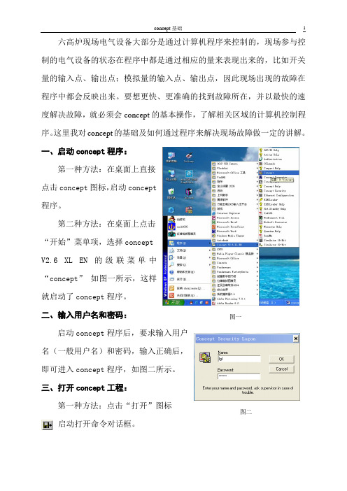
六高炉现场电气设备大部分是通过计算机程序来控制的,现场参与控制的电气设备的状态在程序中都是通过相应的量来表现出来的,比如开关量的输入点、输出点;模拟量的输入点、输出点,因此现场出现的故障在程序中都会反映出来。要想更快、更准确的找到故障所在,并以最快的速度解决故障,就必须会concept的基本操作,了解相关区域的计算机控制程序。这里我对concept的基础及如何通过程序来解决现场故障做一定的讲解。
2,在该对话框中输入相应的变量名或地址,如图十二所示,再要点击图标 联机,即对相应变量进行了强制。
施耐德程序软件concept实际应用培训

施耐德程序软件c o n c e p t实际应用培训Updated by Jack on December 25,2020 at 10:00 am施耐德程序软件concept培训一、培训目的:以翻车机系统逻辑为例,通过观看培训人的操作,参加培训的成员学会软件基本操作,希望把其应用到实际工作中解决问题。
二、主要培训内容1.程序打开方法找到程序文件路径找到,将其拖动到桌面快捷方式,程序自动打开,如下图。
或者先打开软件在文件中选择打开我们要打开的程序。
2.查找程序的方法使用快捷键F3查找,shift+F3跟踪(索源),F8变量表,F5查找历史,例如我们要查找Z_DanCheDW_SQ重调机单车到位信号,使用F3快捷键输入Z_DanCheDW_SQ,可以看到该点所应用到的位置,可以点开第一个来看,然后使用F6查找下一个点所用的位置。
如何索源,使用快捷键shift+F3,跟踪起始点画面左下方的注释带卡件信息的为实点输入100085,该实点位于一号站一号机架第十卡槽,通过下面的方法看该实点位于卡件哪个点。
从上图我们知道100085位于该卡件的第5点。
3.如何模拟程序EQUAL显示程序与控制器中的程序相匹配,可以在线查看。
选择图中画圈的示意图读取布尔量,左侧的按钮为读取所有变量,包括模拟量。
如果我们要局部修改程序,选择设备停运的时候进行局部下载,选择online中的download changes,在下载后程序仍然是equal状态。
4.如何强制条件及解强例如我们要强制F_BP_HeZha_NO翻车机变频器合闸信号为1,使用快捷键CTROL+R打开数据编辑器,点击toggle按钮进行在线读点,先点击disable,在VALUE 中输入1回车将变量表关闭选择不保存,(如果保存,保存为文件,)如何解除强制,点击Enable all 或者选择001001 点击enable selected恢复后的程序如下。
我们在程序中工作的时候,务必要专心,鼠标不要随意拖动,在程序中结束工作的时候要注意右下方仍然显示equal,最后选择DISCONNECT,断开程序的连接。
