CUT-60材料清单
设备验收检查清单
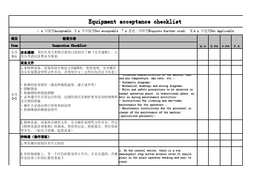
3.启动控制按钮是绿色的;控制盘的位置应该允许操作员手动操作机器时可以直视部件的移动。
3.The control/start button is green;The controlpanel is positioned in the place where the user has direct line of sight of the moving parts when the machine is run in manual mode.4.指示灯及按钮颜色应该符合以下标准(GB2682-81->IEC60073)•指示灯:红---紧急情况、危险状态或须立即采取行动;压力/温度超越安全状态;因保护器件动作而停机;有触及带电或运动的部件的危险。
黄---不正常、注意不正常状态;临近临界状态压力/温度超过正常范围;保护装置释放;当仅能承受允许的短时过载。
绿---安全、正常状态;允许进行压力/温度在正常状态;自动控制系统运行正常;蓝---强制性;表示需要操作人员采取行动输入指令白---没有特殊意义、其它状态;如对红。
黄。
绿或蓝存在不确定时,允许使用白色一般信息;不能确切地使用红。
黄。
绿时;用作“执行”确认指令时;指示测量值。
5.Control buttom & Lamp should comply to following rules(GB2682-81->IEC60073)控制系统安全及可靠性(程序逻辑)1.控制系统的软/硬件失效,逻辑错误不应使人员或设备处于危险状态(使用安全逻辑控制)1.A fault in the hardware or the software of thecontrol system,Errors in the control system logicshall not lead to hazardous situations.(Usingsafety logic in control system)shall not lead to hazardous situations ?2.设备不应突然启动2.The machinery shall not start unexpectedly.3.设备运动部分或产品应不太可能掉落或被夹住3.Any moving part of the machinery or piece held by the machinery shall not fall or be ejected often4.在无线控制系统信号不良的状态下设备应自动停止 4.For cable-less control, an automatic stop activated when correctcontrol signals are not received, including loss紧急停止STOP(all safety devices need to connect to safety)1.所有机器必须合适地、分散地安装急停开关以便操作员在任何工位都能按到1.All machines must be equipped with emergencystops properly distributed so that they areaccessible to the operator from any "workstation"on the machine.安全S-3安全S-4安全3.如果不能实现物理永久隔离,那么将采取以下措施确保安全:• 提供防护门:在打开之后没有风险,此装置必须允许在正常运行状态下打开将关闭机器或设备。
用友U8物料清单操作手册

科丝发原料目录by080214
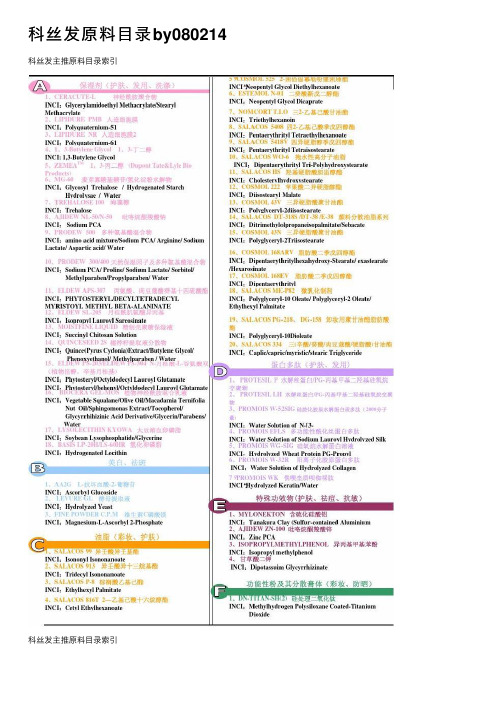
科丝发原料⽬录by080214科丝发主推原料⽬录索引科丝发主推原料⽬录索引1、CERACUTE-L神经酰胺聚合物独创的模仿神经酰胺的结构设计⽽成的功效性素材。
对肌肤具有良好的亲和性,在⽪肤表⾯形成神经酰胺的⽹状结构,赋予肌肤柔软性、弹性和屏障功能。
特别是对眼部皱纹有明显的改善。
在各种油脂中有良好的相溶性。
●膏霜产品:1.0-2.0%●精华素: 1.0-2.0%●祛皱产品: 1.0-2.0%2、LIPIDURE PMB⼈造细胞膜是⼀种模仿细胞膜来设计的⼈造细胞膜,⽐透明质酸具有更佳的吸湿保湿性,更好的锁住⽪肤和头发的⽔分,给予更长久的滋润和爽滑感。
是活体亲和性原料,安全性⾼,并且具有抑制⽪肤皲裂效果。
应⽤范围极⼴的划时代的原料。
●膏霜产品:0.2-2.0%●精华素: 0.5-2.0%●祛皱产品: 0.5-5.0%3、LIPIDURE NR⼈造细胞膜2是⼀种模仿细胞膜来设计的⼈造细胞膜,⽐透明质酸具有更佳的吸湿保湿性,更好的锁住⽪肤和头发的⽔分,给予更长久的滋润和爽滑感。
能够在⽪肤表⾯形成层状的膜,使得保湿效果更长久,肤感更滑爽;作为活体亲和性原料,具有极⾼的安全性,并且具有抑制⽪肤皲裂效果。
应⽤范围极⼴的划时代的原料。
●膏霜产品:0.2-2.0%●精华素: 0.5-2.0%●祛皱产品: 0.5-5.0%4、1,3-Butylene Glycol1,3-丁⼆醇(⽇本DAICEL公司⽣产)⼀种具有滑爽感觉的保湿剂,具有良好的分散性,抗菌性好等特点。
是⽆⾊⽆味透明液体,配伍性好,较易与其他化妆品原料配合使⽤。
具有⼀定防腐功能,使⽤时可减少配⽅中的防腐剂⽤量。
本品为市售同类商品中纯度最⾼,⽓味最少的产品。
●护肤产品:4.0-10.0%●洗涤产品:2.0-10.0%●护发产品:2.0-10.0%5、ZEMEA TM1,3-丙⼆醇(Dupont Tate&Lyle Bio Products)⽟⽶来源的⾼纯度丙⼆醇。
ERP 专业术语
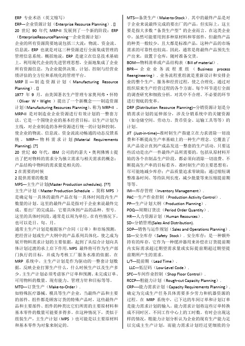
ERP 专业术语(英文缩写)ERP---企业资源计划(Enterprise Resource Planning). [] 20 世纪90 年代MRP-II 发展到了一个新的阶段:ERP (EnterpriseResourcePlanning—企业资源计划)企业的所有资源简要地说包括三大流:物流、资金流、信息流,ERP 也就是对这三种资源进行全面集成管理的管理信息系统。
概括地说,ERP 是建立在信息技术基础上,利用现代企业的先进管理思想,全面地集成了企业所有资源信息,为企业提供决策、计划、控制与经营业绩评估的全方位和系统化的管理平台。
MRPⅡ---制造资源计划(Manufacturing Resource Planning). []1977 年9 月,由美国著名生产管理专家奥列弗·怀特(Oliver W·Wight )提出了一个新概念——制造资源计划(Manufacturing Resources Planning),称为MRP-II 。
MRP-II 是对制造业企业资源进行有效计划的一整套方法。
它是一个围绕企业的基本经营目标,以生产计划为主线,对企业制造的各种资源进行统一的计划和控制,使企业的物流、信息流、资金流流动畅通的动态反馈系统。
MRP---物料需求计划(Material Requirements Planning). [?]20 世纪60 年代,IBM 公司的约瑟夫·奥利佛博士提出了把对物料的需求分为独立需求与相关需求的概念:产品结构中物料的需求量是相关的。
2在需要的时候2提供需要的数量MPS---主生产计划(Master Production schedules). [??]主生产计划(Master Production Schedule ,简称MPS )是确定每一具体的最终产品在每一具体时间段内生产数量的计划。
这里的最终产品是指对于企业来说最终完成、要出厂的完成品,它要具体到产品的品种、型号。
v-cut作业指导书
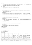
1.0、目的建立设备操作详细作业规范,籍以稳定产品质量,提高生产效率,确保生产安全,并作为设备保养及操作的依据,此份文件同时也是本岗位新进员工培训之教材。
2.0、适用范围本作业规范适用于加工-成型.手动V-CUT机的操作及保养。
3.0、定义和职责3.1 V-CUT是将成型后有多连片或带折断边的PCB板,做V型槽切割.确保一定的余留厚度,以方便客户插件后分割拆解的加工要求。
3.2 制造部职责:3.2.1 员工按研发部提供之参数制造符合要求的产品并做好相关的记录,组长对此进行监督和审核。
3.2.2 员工按规定的要求进行机器操作和设备的日常保养、维护、点检,并做好相应的记录,组长对此进行监督和审核。
3.2.3 组长负责对员工进行安全生产操作的培训和考核。
3.3 品保部职责:3.3.1 IPQC人员负责监督实施力度,对制造部的质量、保养、操作.作业参数和作业环境稽核并保证产品符合客户要求。
3.4 维修部职责:3.4.1 机器的周、月、年的保养和维护并按要求做好相关的记录。
3.5 研发部职责:3.5.1 评估和提供生产过程中各种参数要求及其实现方法。
4.0参考文件和数据4.1制作流程工单。
4.2工程机械成型机构图或客户提供成型图。
4.3工程变更通知单(ECN)。
4.4具体特别操作指示。
7.1操作示意图7.2 V-CUT 机开机操作流程8.0 工艺操作过程及操作要求:N/A 9.0 操作要求9.1 V-CUT 机操作要求流程 操作要求9.2 异常现象原因分析及改善措施9.2.1 露铜、露线、偏位原因:在生产过程中此类异常是较为常见的,造成此异常的主要原因是V-CUT机前后挡板松动及锣板在生产过程中有板大小不一造成。
改善措施:操作员在生产操作过程中要做到定时自检,定时查看V-CUT机文挡板是否有松动,在生产锣板的尺寸有不一致的须将尺寸不一的板挑出分开V-CUT并做到3-5SET自检一次。
9.2.2 跳刀原因:造成板在V-CUT过程中跳刀主要是因为刀具上有缺口和压板胶轮不转造成改善措施:操作员在调刀前必须有对胶轮进行检查,对废弃和有缺口的刀具应分开放置或打报废,胶轮须经常保养使其润滑表面无锈。
等离子切割 耗材-概述说明以及解释

等离子切割耗材-概述说明以及解释1.引言1.1 概述等离子切割是一种常用的金属加工技术,通过将高温等离子切割火焰引导到工件表面,使金属材料熔化并迅速气化,然后利用高速高温的等离子切割火焰将金属材料切割成所需形状。
该技术被广泛应用于金属制造、建筑、汽车制造等领域。
耗材是指在等离子切割过程中需要使用的各种辅助材料和设备。
常见的耗材包括氧气、乙炔等燃料气体以及切割嘴、切割丝等切割设备。
氧气和乙炔是等离子切割中最常用的燃料气体,它们燃烧后产生的高温等离子切割火焰可以将金属材料迅速切割。
切割嘴是将燃料和氧气注入切割区域并形成稳定等离子切割火焰的关键部件,切割丝则是用于支撑并引导切割火焰的金属丝。
耗材的选择和使用对等离子切割的效果和成本都有着重要影响。
不同的金属材料需要不同类型和比例的燃料气体,以及适配的切割嘴来实现最佳切割效果。
同时,合理使用耗材和进行维护保养,可以延长耗材的使用寿命,减少切割成本和能源消耗。
随着科技的进步和等离子切割技术的不断发展,耗材的种类和性能也在不断提升。
例如,一些新型耗材具有更好的耐磨性、抗腐蚀性和导热性能,使得切割效果更加高效和精确。
总之,等离子切割作为一种重要的金属加工技术,其概述和耗材是我们必须了解的基础知识。
了解等离子切割原理和正确选择、使用耗材,可以提高切割效果,降低成本,推动相关行业的发展。
1.2 文章结构文章结构部分的内容可以包括以下内容:文章结构部分主要介绍了整篇文章的组织结构,以便读者更好地理解文章的脉络和内容安排。
首先,本文包括引言、正文和结论三个部分。
引言部分主要包括概述、文章结构和目的三个小节,用于引导读者进入文章的主题。
在正文部分,首先介绍了等离子切割的相关知识。
这部分可以从等离子切割的原理、应用领域以及发展历程等方面展开,向读者阐述等离子切割的基本概念和重要性。
接下来的小节则是介绍了等离子切割所涉及的耗材。
这部分可以从耗材的种类、用途以及选购等方面进行介绍,为读者提供了解耗材的基本知识和选购指南。
PRO-CUT 60单相氧化碳切割系统运营员手册说明书
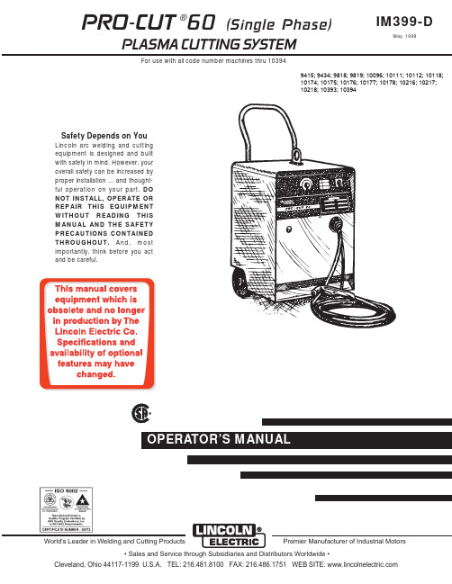
PRO-CUT 60 (Single Phase)PLASMA CUTTING SYSTEMFor use with all code number machines thru 10394IM399-DMay, 1999Safety Depends on YouLincoln arc welding and cutting equipment is designed and built with safety in mind. However, your overall safety can be increased by proper installation ... and thought-ful operation on your part.DO NOT INSTALL, OPERATE OR REPAIR THIS EQUIPMENT WITHOUT READING THIS MANUAL AND THE SAFETY PRECAUTIONS CONTAINED THROUGHOUT.And, most importantly, think before you act and be careful.®•Sales and Service through Subsidiaries and Distributors Worldwide •World's Leader in Welding and Cutting ProductsPremier Manufacturer of Industrial Motors9415; 9434; 9818; 9819; 10096; 10111; 10112; 10118; 10174; 10175; 10176; 10177; 10178; 10216; 10217; 10218; 10393; 10394for selecting a QUALITY product by Lincoln Electric. We want you to take pride in operating this Lincoln Electric Company product ••• as much pride as we have in bringing this product to you!Read this Operators Manual completely before attempting to use this equipment. Save this manual and keep it handy for quick reference. Pay particular attention to the safety instructions we have provided for your protection.The level of seriousness to be applied to each is explained below:PRODUCT DESCRIPTIONThe PRO-CUT®60 is a constant current, single range, continuous control plasma cutting system. It provides excellent starting characteristics, cutting visibility and arc stability. The torch has a patented safety mecha-nism which insures that the consumables are in place before cutting or gouging. This is extremely important due to the high voltages involved.The PRO-CUT 60 comes standard with air regulator, coarse air filter, oil coalescing filter, and pressure gauge. The Pro-Cut 60 comes ready to use with the torch attached. Machines equipped with handheld torches are available with either 25 ft. (7.6m) or 50 ft.(15.2m) torch cable. The undercarriage is standard and is shipped assembled except for the handle. The machine is capable of cutting with nitrogen or air. Nitrogen is used to cut aluminum and other nonfer-rous metals.The PRO-CUT is controlled by a microprocessor-based system. The machine performs rudimentary self troubleshooting when powered up, which aids in field servicing.PREHEAT TEMPERATURE FOR PLASMA CUTTINGPreheat temperature control is recommended for opti-mum mechanical properties, crack resistance and hardness control. This is particularly important on high alloy steels and heat treated aluminum. Job con-ditions, prevailing codes, alloy level, and other consid-erations may also require preheat temperature con-trol. The following minimum preheat temperature is recommended as a starting point. Higher tempera-tures may be used as required by the job conditions and/or prevailing codes. If cracking or excessive hardness occurs on the cut face, higher preheat tem-perature may be required. The recommended mini-mum preheat temperature for plate thickness up to 1/2 inch (12.7m) is 70 (°F) (21.1°C).USER RESPONSIBILITYBecause design, fabrication, erection and cutting vari-ables affect the results obtained in applying this type of information, the serviceability of a product or struc-ture is the responsibility of the user. Variation such as plate chemistry, plate surface condition (oil, scale), plate thickness, preheat, quench, gas type, gas flow rate and equipment may produce results different than those expected. Some adjustments to procedures may be necessary to compensate for unique individ-ual conditions. Test all procedures duplicating actual field conditions.INPUT CONNECTIONSpower company if there is any question about whether your power supply is adequate for the voltage,amperes, phase, and frequency specified on the machine nameplate. Also be sure the planned instal-lation will meet the any National Electrical Code and local code requirements. This machine may be oper-ated from a single phase line or from one phase of a two or three phase line.Models that have multiple input voltages specified on the nameplate (e.g. 208/230/460) are shipped con-nected for the highest voltage. If the machine is to be operated on the lower voltage, it must be reconnected according to the instructions on the inside of the removable panel in the center of the rear panel.Machine supply line entry provision is next to the removable panel.L1 and L2 of the terminal block in accordance with any National Electrical Code, all local codes and the connection diagram located on the inside of the e ferrules provided (S19117-1) for #10 wire. No ferrule is required for #8 wire. Tighten screws to 16in/lbs. (1.8 N.M.). See below.Strip Required for #10 (5.3mm 2) Wire• The .035” (0.8mm) nozzle may be used for afine cut. Larger nozzles will work and providelonger life at the expense of a larger cut.• Do not allow the torch cable or body to contacthot surface.•The best quality cut is obtained by reducing thecurrent to a level that is adequate for the maxi-mum travel speed.•Aluminum, copper and other nonferrous metalstypically require more current than the samethickness of steel. Treat these as a thicker sec-tion of steel if good results are not obtained. Expanded Metal:Output set near mid-range.• Cut it as you would light gauge sheet metal.• Expanded metal is pilot arc intensive. Afterabout 30 seconds of cutting, the pilot arc willchange from a bright continuous arc to a discon-tinuous one which will sputter slightly. It will stayin this mode as long as metal has been cut inthe previous 5 seconds. If metal is not cut in theprevious 5 seconds, the arc will shut off and themachine will go into postflow.•If the trigger is continuously pressed andreleased to obtain the bright pilot arc for longperiods of time, the machine will go into pilot arcduty cycle limit. This is a 20 seconds out of 80seconds pilot duty cycle. The pilot arc is dis-abled in the limit period. Pilot arc duty cyclelimit is indicated by alternately flashing “OUT-PUT ON” and “FAULT” LED’s.• Placing a thin piece of scrap sheet metal abovethe area to be cut and cutting through both canmake the job easier.• Do not allow the torch cable or body to contacthot surfaces.Thick Sections of MetalOutput set above mid-range.• The best quality and consumable life will beobtained by holding the torch nozzle off the sur-face about 1/8” (3.2mm). Output control shouldbe sent in the red range only. Do not touch thenozzle to the work or carry a long arc.• Use the S24114 Drag Cup to protect the torch.The only reason not to use the Drag Cup whenthe output control is in the blue or red regions isin special tight corners. Always hold at least a1/8” (3.2mm) standoff in those situations anduse the S18817 shield cup.• Set the current to the minimum necessary tomake the cut.•Use the .052” or .042” (1.2 or 1.0mm) nozzlesize.DO NOT use the .035” (0.8mm) nozzle.• Pierce the plate by slowly lowering the torchonto it at an angle of about 30°to blow thedross away from the torch tip and slowly rotatethe torch to a vertical position as the arcbecomes deeper.• Where possible, start the cut from the edge ofthe workpiece.• Keep moving! A steady speed is necessary.Do not pause.•Do not allow the torch cable or body to contacthot surfaces.Gouging:Output set to maximum.• Use the gouging nozzle S18497-4• Use the Shield Cup.• Bring the torch slowly towards the work at abouta 30°angle as if piercing the plate. Blow themolten metal away from the torch.• Do not touch the nozzle to the work.• The air pressure may be raised to about 75 psi(517 kPa) to aid in metal removal.• This process will blow a lot of molten metal anddross.BE CAREFUL!Blow the dross awayfrom the torch, away from the operator andaway from flammable objects.• Do not allow the torch cable or body to contacthot surfaces.• Performance is similar to air carbon arc gougingwith a 1/8” (3.2mm) carbon electrode.– 21–– 22–L 10294W I R I N G D I A G R A M - P R O -C U T 60 (S I N G L E P H A S E )N O T E : T h i s d i a g r a m i s f o r r e f e r e n c e o n l y . I t m a y n o t b e a c c u r a t e f o r a l l m a c h i n e s c o v e r e d b y t h i s m a n u a l . T h e s p e c i f i c d i a g r a m f o r a p a r t i c u l a r c o d e i s p a s t e d i n s i d e t h e m a c h i n e o n o n e o f t h e e n c l o s u r e p a n e l s . I f t h e d i a g r a m i s i l l e g i b l e , w r i t e t o t h e S e r v i c e D e p a r t m e n t f o r a r e p l a c e m e n t . G i v e t h e e q u i p m e n t c o d e n u m b e r ..July96– 23–FIGURE 1- Dual VoltageFIGURE 1- Triple VoltageMay96FIGURE 2– 24–May96Now Available...12th EditionThe Procedure Handbook of Arc WeldingWith over 500,000 copies of previous editions published since 1933, the Procedure Handbook is considered by many to be the “Bible” of the arc welding industry.This printing will go fast so don’t delay. Place your order now using the coupon below.The hardbound book contains over 750 pages of welding information, techniques and procedures. Much of this material has never been included in any other book.A must for all welders, supervisors, engineers and designers. Many welding instructors will want to use the book as a reference for all students by taking advantage of the low quantity discount prices which include shipping by 4th class parcel post.$15.00postage paid U.S.A. MainlandHow To Read Shop DrawingsThe book contains the latest information and application data on the American Welding Society Standard Welding Symbols. Detailed discussion tells how engineers and draftsmen use the “short-cut” language of symbols to pass on assembly and welding information to shop personnel.Practical exercises and examples develop the reader’s ability to visualize mechanically drawn objects as they will appear in their assembled form.187 pages with more than 100 illustrations. Size 8-1/2” x 11”Durable, cloth-covered board binding.$4.50postage paid U.S.A. MainlandNew Lessons in Arc WeldingLessons, simply written, cover manipulatory techniques;machine and electrode characteristics; related subjects,such as distortion; and supplemental information on arc welding applications, speeds and costs. Practice materials,exercises, questions and answers are suggested for each lesson.528 pages, well illustrated, 6” x 9” size, bound in simulated,gold embossed leather.$5.00postage paid U.S.A. MainlandNeed Welding Training?The Lincoln Electric Company operates the oldest and most respected Arc Welding School in the United States at its corporate headquarters in Cleveland, Ohio. Over 100,000stu-dents have graduated. Tuition is low and the training is “hands on”For details write:Lincoln Welding School 22801 St. Clair Ave.Cleveland, Ohio 44117-1199.and ask for bulletin ED-80 or call 216-383-2259 and ask for the Welding School Registrar.Lincoln Welding SchoolBASIC COURSE $700.005 weeks of fundamentalsThere is a 10%discount on all orders of $50.00 or more for shipment at one time to one location.Orders of $50 or less before discount or orders outside of North America must be prepaid with charge, check or money order in U.S. Funds Only.Prices include shipment by 4th Class Book Rate for U.S.A. Mainland Only.Please allow up to 4 weeks for delivery.UPS Shipping for North America Only.All prepaid orders that request UPS shipment please add:$5.00For order value up to $49.99$10.00For order value between $50.00 & $99.99$15.00For order value between $100.00 & $149.00For North America invoiced orders over $50.00 & credit card orders, if UPS is requested, it will be invoiced or charged to you at cost.Outside U.S.A. Mainland order must be prepaid in U.S. Funds. Please add $2.00 per book for surface mail or $15.00 per book for air parcel post shipment.METHOD OF PAYMENT:(Sorry, No C.O.D. Orders)CHECK ONE:Name:_______________________________________________❐Please Invoice (only if order is over $50.00)Address:_______________________________________________❐_______________________________________________❐Credit Card - ❐❐Telephone:_______________________________________________Signature as it appears on Charge Card:Account No.|_|_|_|_|_|_|_|_|_|_|_|_|_|_|_|_|_|_|_|_|_|Exp Date|_|_||_|_|______________________Month YearUSE THIS FORM TO ORDER:Order from:BOOK DIVISION, The Lincoln Electric Company, 22801 St. Clair Avenue, Cleveland, Ohio 44117-1199BOOKS OR FREE INFORMATIVE CATALOGS Telephone: 216-383-2211 or, for fastest service, FAX this completed form to: 216-361-5901.Lincoln Welding School ❐Titles:Price Code QuantityCost(ED-80)New Lessons in Arc Welding $5.00L Seminar Information ❐Procedure Handbook “Twelfth Edition”$15.00PH (ED-45)How to Read Shop Drawings $4.50H Educational Video Information ❐Incentive Management $5.00IM (ED-93) A New Approach to Industrial Economics $5.00NA James F. Lincoln Arc Welding The American Century of John C. Lincoln $5.00AC Foundation Book Information ❐Welding Preheat Calculator $3.00WC-8(JFLF-515)Pipe Welding Charts $4.50ED-89SUB TOTALAdditional Shipping Costs if anyTOTAL COSTJapaneseChineseKoreanArabicREAD AND UNDERSTAND THE MANUFACTURER’S INSTRUCTION FOR THIS EQUIPMENT AND THE CONSUMABLES TO BE USED AND FOLLOW YOUR EMPLOYER’S SAFETY PRACTICES.SE RECOMIENDA LEER Y ENTENDER LAS INSTRUCCIONES DEL FABRICANTE PARA EL USO DE ESTE EQUIPO Y LOS CONSUMIBLES QUE VA A UTILIZAR, SIGA LAS MEDIDAS DE SEGURIDAD DE SU SUPERVISOR.LISEZ ET COMPRENEZ LES INSTRUCTIONS DU FABRICANT EN CE QUI REGARDE CET EQUIPMENT ET LES PRODUITS A ETRE EMPLOYES ET SUIVEZ LES PROCEDURES DE SECURITE DE VOTRE EMPLOYEUR.LESEN SIE UND BEFOLGEN SIE DIE BETRIEBSANLEITUNG DER ANLAGE UND DEN ELEKTRODENEINSATZ DES HER-STELLERS. DIE UNFALLVERHÜTUNGSVORSCHRIFTEN DES ARBEITGEBERS SIND EBENFALLS ZU BEACHTEN.JapaneseChineseKoreanArabicLEIA E COMPREENDA AS INSTRUÇÕES DO FABRICANTE PARA ESTE EQUIPAMENTO E AS PARTES DE USO, E SIGA AS PRÁTICAS DE SEGURANÇA DO EMPREGADOR.• Sales and Service through Subsidiaries and Distributors Worldwide •Cleveland, Ohio 44117-1199 U.S.A. TEL: 216.481.8100 FAX: 216.486.1751 WEB SITE: World's Leader in Welding and Cutting ProductsPremier Manufacturer of Industrial MotorsMarch, ‘99。
辐射交联聚乙烯热收缩带(套)及补伤片技术规格书

收缩带/套型号、管道直径,用户名称和地点,联系电话,供货年份及使用情况等。
3.1.3 强制技术条款
供货商应提供 ISO9001 质量保证体系认证证书,以及由通过国家计量认证的检测
机构出具的 12 个月内的第三方检验报告,检测报告应包括本技术规格书规定的全部检
测项目。
3.2 投标承诺
3.2.1 供货商职责
低要求,并不减轻供货商为其所提供的辐射交联聚乙烯热收缩带/套及补伤片的设计、
制造、装配、检测、试验、性能和安全所负的全部责任。
供货商应对提供辐射交联聚乙烯热收缩带/套及补伤片的质量、可靠性、使用寿
命、技术服务、相关责任等做出承诺。
业主使用时发生性能不合格等质量问题,供货商要赔偿由此带来的所有损失和性材料对刚性材料)
GB/T 15332 热熔胶粘剂软化点的测定 环球法
GB/T 8923
涂覆涂料前钢材表面处理
GB/T 20027 GB/T 23257
橡胶或塑料涂覆织物 破裂强度的测定 埋地钢质管道聚乙烯防腐层
技术规格书
单位:河南汇龙合金材料有限公司 第 2 页 共 16 页
SY/T 0414 SY/T 0447
钢质管道聚乙烯胶粘带防腐层技术标准 埋地钢质管道环氧煤沥青防腐层技术标准
其它未列出的与本产品有关的标准规范,供货商有义务主动向业主和设计提供。
所有标准规范均应为项目采购期时的有效版本。
5 供货范围及界面
在合同规定的时间内提供的供货范围应包括但不限于以下内容:
1) 带配套环氧底漆的辐射交联聚乙烯热收缩带/套;
技术规格书
单位:J河南汇龙合金材料有限公司
辐射交联聚乙烯热收缩带 (套)及补伤片
专业:防腐及阴极保护 日期:2019 年 11 月 11日
手术室耗材明细

一次性穿刺器
单支/套装
培养皿
微创扩张引流套件
胆道镜结石取出器
EMS探针
F8-F22
标本取物袋
滑导丝
线锯条
硬导丝
脑外冲洗器
进口经皮肾导引针
进口脑积水分流器
防粘连类
医用几丁糖凝胶
电切冲洗液
医用生物胶(术尔泰)
医用润保
抗菌除尘垫
一次性床罩
甲醛标本固定液
麻醉耗材明细
类别
品名
型号
穿刺类
联合麻醉包
Ⅱ型
腰穿针
F14-F18
生物型硬脑脊膜补片
0505
F8-F10
0812
进口金属肿瘤支架管
切割
吻合类
腔内切缝器、钉仓
进口脑积水分流器
直线型切割吻合器
100切
进口一次性使用多腔道内窥镜导管
100钉
内固定
材料
肋骨固定板
75切
记忆合钉
75钉
胸骨固定板
管型吻合器
标本
容器及其他类
标本袋
A型
圆弧切割吻合器
B型
缝合器组件
C型
手术室耗材明细
手术室耗材明细
类别
品名
型号
类别
品名
型号
器械类
腔镜器械
进口、国产
缝针
缝线
可吸收性外科缝线
腹腔镜配件及器械
进口、国产
非吸收性外科缝线
宫腔镜配件及器械
进口、国产
双向倒刺免打结缝线
输尿管镜、肾镜配件及器械
进口、国产
可吸收胶原蛋白缝线
关节镜配件及器械
进口、国产
无菌组合针(定制)
RoHS最新豁免清单
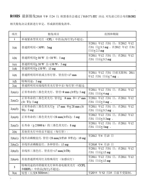
ROHS 最新豁免2010 年9 月24 日,欧盟委员会通过了010/571/EU 决议,对先前已经公布的ROHS 相关豁免决议重新进行审定,形成新的豁免清单。
1、根据欧盟ERP 指令中244/2009/EC 、245/2009/EC 指令要求,对荧光灯管中汞含量进行细化;荧
光灯管中汞的测试按2002/747/EC 决议规定进行测试,取10 只灯管测试汞,去掉一个最大值和一个最小值,求出剩下8 只灯管的汞的算术平均值,即为灯管的汞含量;
2、铜合金、钢合金、铝合金,故意添加铅元素以便机械加工,也称为切削(cut-free)合金或加工合
金;注意,并不是所有铜合金、钢合金、铝合金都故意添加铅,亦即并不是所有铜合金、钢合金、铝合金都允许含铅;注意材料用途,如电源铜插头、某些铁销等;
3、高温焊料一般用于大功率易发热元件,如CPU、整流二极管、功率三极管、可控硅等,这些元件
在工作时会产生高热,必须采用高温焊锡;
4、服务器,存储器和存储系统,以及交换,信号和传输、电信网络管理的网络基础设施,需要高可
靠性长时间连续运转,无铅焊锡还不成熟,不足以保证这些设施长时间连续可靠运转,只能用有铅焊料,进一步,如果元件是准备用于这些设施,其引脚也是可以镀有铅焊锡的;
5、陶瓷或玻璃元件中铅豁免,突破了原条款中仅针对压电陶瓷的举例,如PTC 也是可以豁免的;
6、光学玻璃一般为特定的光学仪器上所用玻璃;
7、其他豁免属于较专门用途,不做说明。
Cutmaster60i 与 SL60QD1Torch 产品说明书

The new frontier in plasmaIndustryAgricultural Equipment Automotive BodiesConstructionFabricationGeneral Manufacturing HVACRepair and Maintenance Training Schools The Cutmaster®60i with SL60QD™1Torch®is the perfect combination of end-user insight, advanced technology, and intelligent design. Packed with power and offering the highest power-to-weight ratio in its class, the Cutmaster60i with SL60QD 1Torch also has best in class cutting arc length and the most empowering and engaging user experience no matter the application.7.6 kW rated output, 50% Duty Cycle at 60A built forportability and durability with the integral multi-handle designSL60QD 1Torch quick disconnect with ATC®(Advanced Torch Connector) allowing selectivereplacement of either the torch handle assembly or the torch leads, using the patented SureLok®technology also available as an RPT Torch16 mm recommended cut capacity with greater than32 mm maximum cut and 16 mm pierceHigh-visibility, oversized display with gas optimizer technology and consumables end-of-life indicatorIndustry leading 3-year warranty on power supply and 1-year warranty on torchVisit for more information.Replace ConsumablesSL60 ConsumablesSpecificationsAmperage Output10 –60 A, continuously adjustable Rated Output Power7.6 kWOpen Circuit Voltage (OCV)300 VInput Voltage400 VACNumber of Phases 3 phSupply Frequency50/60 HzRated Duty Cycle 50% @ 60 A 60% @ 50 A 100% @ 40 AAmperage Draw13.2 A @ 400 VInput Power Cable and Plug 2.7 mWork Lead with Ground Clamp 6 m #8 work cable with 50 mm connection Gas Requirements Compressed airOperating Temperature Range0°-50°COperating Input Air Pressure Range 6.2 –8.6 barAir Flow Requirements (cutting & gouging)142 –235 l/mPower Supply Gas Filtering Ability Particulates to 5 Microns Recommended Cut16 mmMaximum Sever38 mmPierce Rating16 mmSL60QD Torch Duty Cycle100% at 60 A @ 400 scfh air flowTorch Air Pressure 5.2 barTorch Air Consumption190 l/sTorches –for use with the Cutmaster 60i SL60QD 1Torch (supplied) SL60/SL100 1TorchSL100 Mechanized 1Torch SL100SLV Automated 1TorchDimensions L x W x H536 x 199 x 359 mmWeight16.2 kgCutting SpecificationsPlate Thickness Recommended Cut Speed Maximum Cut Speed6 mm 2030 mm/min 2794 mm/min13 mm 660 mm/min 914 mm/min16 mm 480 mm/min 610 mm/min19 mm 360 mm/min Contact ESAB for specific application 25 mm150 mm/min Contact ESAB for specific application 32 mm110 mm/min Contact ESAB for specific application 38 mm110 mm/min Maximum SeverOrdering Information -SystemsESAB Cutmaster60i 3ph w. SL60QD 1Torch 6.1 m 75°Head0559156304ESAB Cutmaster60i 3ph w. SL60QD 1Torch 15.2m 75°Head0559156314ESAB Cutmaster60i 3ph Power Supply Only0559356304TorchesSL60QD Torch and Lead 20’ (6.1 m) 75°Head7-5604SL60QD Torch and Lead 50’ (15.2 m) 75°Head7-5605SL60QD Torch Handle Assembly75°Head (no leads)7-5680SL60QD Lead 20’ (6.1 m)4-5604SL60QD Lead 50’ (15.2 m)4-5605SL60 Torch and Lead 20’ (6.1 m) 75°Head7-5204SL60 Torch and Lead 50’ (15.2 m) 75°Head7-5205SL60 Torch and Lead 20’ (6.1 m) 90°Head7-5260SL100Mechanized Torch 5’ (1.5 m) 180°Body7-5213SL100Mechanized Torch 10’ (3.0 m) 180°Body7-5214SL100Mechanized Torch 25’ (7.6 m) 180°Body7-5215SL100Mechanized Torch 50’ (15.2 m) 180°Body7-5216Packages Include: Cutmaster60i power supply, SL60QD 75°torch with lead,6.1 m work lead with ground clamp, spare parts kit, operating manual,and filter wrench.Wear and Spare Parts 1TorchElectrode9-8215Start Cartridge9-8213Standoff Guide9-8281Shield Cup9-8218Shield Cup Max Life9-8237Shield Cap Gouging9-8241Shield Cap (Drag only)9-8235Shield Cap Deflector9-8243Tip –Drag (60 A)9-8252Tip –Standoff (60 A)9-8210Tip –“A” Gouging, (40 A Max), Profile: Shallow/Narrow9-8225Tip –“B” Gouging, (50 –100 A), Profile: Deep/Narrow9-8226Tip –“C” Gouging, (60 –120 A), Profile: Moderate/Moderate9-8227Tip –“D” Gouging, (60 –120 A), Profile: Shallow/Wide9-8228X A 00191820 R e v 1 04/2018 E S A B r e s e r v e s t h e r i g h t t o a l t e r s p e c i f i c a t i o n s w i t h o u t p r i o r n o t i c e .Options & AccessoriesCutting Guide Kit (Deluxe)7-8910Circle Cutting Guide Kit 7-3291Filter Wrench9-9675Hand Pendant Extension 25 ft. (7.6 m)7-7744Lead Extension, 15 ft. (4.6 m)7-7544Lead Extension, 25 ft. (7.6 m)7-7545Lead Extension, 50 ft. (15.2 m)7-7552Leather Lead Covers 20 ft. (6.1 m)9-1260Multi-Purpose Cart7-8888Radius/Roller Cutting Guide Kit 7-7501Remote Pendant Control 20 ft. (6.1 m)7-3460Single Stage Air Filter Kit 7-7507Straight Line Cutting Guide 7-8911Two Stage Air Filter Kit9-9387Work Cable #8 with Ground Clamp and 50 mm Plug9-9692ESAB / Drag Tip CuttingThe preferred method of cutting light gauge metal up to 6 mm thickness. Produces the best cut quality narrowest kerf width, fastest cuttingspeeds, and with little to no distortion. Traditional drag cutting was limited to 40 A or less; now with Thermal Dynamics TRUE Cut Drag Tip Series™ technology , it is possible to cut up to 60 A. For best results, use the Shield Cup with the torch tip in direct contact with the work (up to 60 A).Standoff CuttingThe preferred method of cutting metal thicker than 6 mm and at current levels above 60 A. Provides maximum visibility and accessibility. Shield cup for 'standoff' cutting (with the torch tip 3 mm to 6 mm from the work piece). Use the shield cup body together with the deflector for extended parts life and improved resistance to reflect heat. Thiscombination provides cutting results similar to the single piece shield cup, as well as easy changeover to gouging or drag shield cutting.Drag Shield CuttingThis is an operator-friendly method of cuttingbetween 70 to 120 A while maintaining a constant standoff distance. For metal thickness greater than 6 mm, simply drag the shield cap in contact with the work piece. Use the shield cup body with the appropriate drag shield cap matching the current level being used. This method is not recommended for cutting light-gauge sheet metal.GougingA simple method of metal removal by angling the torch to a lead angle of 35°-45°, and using a gouging tip. While maintaining a constant standoff distance, this allows for only a partial penetration into the work, thus removing metal from the surface. The amount of current, travel speed, standoff distance, lead angle, and tip size will determine the amount of material removed and the profile of the gouge. You can use the shield cup body with either the gouging shield cap or the shield deflector. Also, you can use the single piece shield cup.1Torch Consumables Parts Application Guide。
Proxxon Micro Chop Saw KGS80-12 Spare Parts List说明

37160 Micro Chop Saw KGS80Please order spare parts in writing fromPROXXON Central Service (Address on back of instruction manual)Part No.: Designation Part No.: Designation Part No.: Designation37160-1Power cable 37160-2Motor27160-3Saw-blade 27160-4Miter bar 27160-5Base27160-6Anchor plate 27160-7Vise27160-8Support 27160-9Table27160-10Clamp handle 27160-11Retaining clip 27160-12Tension handle 27160-13Locating bar 27160-14Plate27160-15Support 27160-16Vise27160-17Spring27160-18Screw27160-19Screw27160-20Screw27160-21Nut chuck 27160-22Nut27160-23Nut27160-24Screw27160-25Washer 27160-26Circlips 27160-27Screw27160-28Screw27160-29Screw27160-30Handle27160-31Screw 27160-32Circlips27160-33Cover27160-34Guard-cord27160-35Motor cover27160-36Pulley27160-37Spacer27160-38Arbor collar27160-39Bracin plate27160-40Cutter shaft27160-41Arm27160-42Motor pulley27160-43Extension spring37160-44Saw-blade guard27160-45Shaft-pivot27160-46Switch handle37160-47Switch27160-48Handle cover27160-49Screw27160-50Screw27160-51Nut27160-52Screw27160-53Washer27160-54Screw27160-55Screw27160-56Circlips27160-57Button switch27160-58Screw37160-59Controller27160-60Drive belt27160-61Compression spring27160-62Ball bearing27160-63Wave washer27160-64Screw27160-65Screw27160-66Washer27160-66Washer27160-67Screw27160-68Clamp cord27160-69Screw27160-70Screw27160-71Screw27160-72Circlips27160-73Screw27160-74Pivot down switch27160-75Shaft pivot27160-76Ferrite27160-77Retaining clip27160-78Rivet27160-79Lever27160-80Rubber pad27160-81Spacer27160-82Tilting scale27160-83O-Ring27160-86Screw27160-87Lock washer37160-88Terminal37160-93Label27160-94Trade mark label37160-95Caution label37160-99ManualSpare parts list for Miter Saw KGS 80, Article No. 37160Prox-Tech, Inc., (“Seller”) warrants to the original purchaser only, that all PROXXON consumer power tools will be free from defects in material or workmanship for a period of two years from the date of purchase. Seller’s sole obligation and your exclusive remedy under this limited warranty and, to the extent permitted by law, any warranty or condition implied by law, shall be the repair or replacement of parts, without charge, which are defective in material or workmanship and which have not been misused, carelessly handled, or misrepaired by per-sons other than Seller or Authorized Service Station. In the event of a failure of a product to conform to this written war-ranty, please refer to the Service and Repair section on the back of this manual and take action accordingly.This Limited Warranty does not apply to accessory items such as circular saw blades, drill bits, router bits, jigsaw blades, sanding belts, grinding wheels and other related items. Dam-age to the product resulting from tampering, accident, abuse, negligence, unauthorized repairs or alterations, unapproved attachments or other causes unrelated to problems with mate-rial or workmanship are not covered by this warranty.Any implied warranties shall be limited in duration to two years from date of purchase. Some states in the U.S. and some Canadian provinces do not allow limitations on how long an implied warranty lasts, so the above limitation may not apply to you.In no event shall seller be liable for any incidental or conse-quential damages (including but not limited to liability for loss of profits) arising from the sale or use of this product. Some states in the U.S. and some Canadian provinces do not allow the exclusion or limitation of incidental or consequential dam-ages; so the above limitation or exclusion may not apply to you. This limited warranty gives you specific legal rights, and you may also have other rights, which vary from state to state in the U.S., province to province in Canada and from country to country. This limited warranty applies only to PROXXON power tools sold within the United States of America, Canada, the commonwealth of Puerto Rico and Mexico. For warranty cov-erage within other countries contact your local PROXXON Importer.LIMITED WARRANTY OF PROXXON POWER TOOLS FOR HOME USE- 12-。
60K,75K 材料表
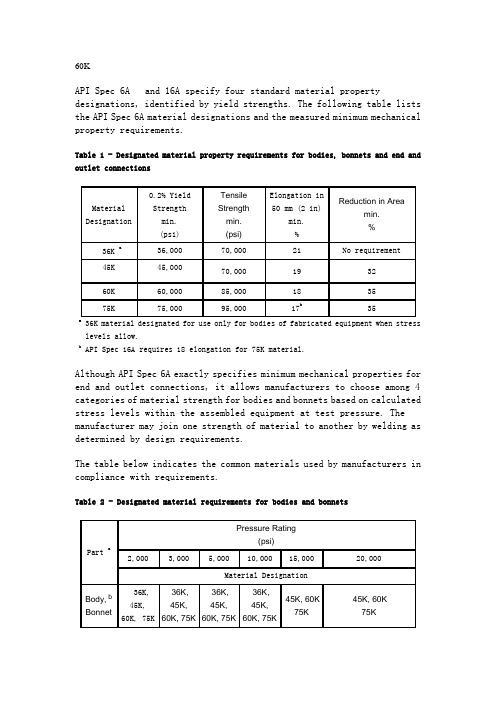
60KAPI Spec 6A and 16A specify four standard material property designations, identified by yield strengths. The following table lists the API Spec 6A material designations and the measured minimum mechanical property requirements.Table 1 - Designated material property requirements for bodies, bonnets and end and outlet connections36K material designated for use only for bodies of fabricated equipment when stress levels allow.b API Spec 16A requires 18 elongation for 75K material.Although API Spec 6A exactly specifies minimum mechanical properties for end and outlet connections, it allows manufacturers to choose among 4 categories of material strength for bodies and bonnets based on calculated stress levels within the assembled equipment at test pressure. The manufacturer may join one strength of material to another by welding as determined by design requirements.The table below indicates the common materials used by manufacturers in compliance with requirements.Table 2 - Designated material requirements for bodies and bonnetsa API Spec 6A Top Connectors shall have bodies, bonnets and collars made from 75Kmaterial.b Bodies may have end and outlet connections of higher strength material, made integral bywelding, in compliance with the requirements of API Spec 6A.Equipment connections need not have any higher material strength than that of the lowest pressure connection. For example, manufacturers may make a 7-1/16 15M x 7-1/16 10M Flanged Adapter Spool entirely from 60K material and meet API Spec 6A requirements. This unit of equipment has a 10,000 psi working pressure, as determined by its' lowest pressure connection, and 60K material meets the minimum mechanical property requirements for 10,000 psi working pressure end connections.The table below lists the material for integral end and outlet connections of pressure containing equipment.Table 3 - Designated material requirements for integral end and outlet connectionsThe table below lists the material requirements for API 6A specified weld neck flanges.Table 4 - Designated material requirements for weld neck flangesSee: Caution: For 6BX Weld Neck Flanges.Commonly, manufacturers use the commercial steels shown in the table below to make API pressure control equipment. NACE specifies all of these materials as satisfactory for Hydrogen Sulfide Service (H2S) per MR0175 provided the hardness does not exceed 22 Rockwell C (22 RC), equivalent to 237 Brinell Hardness (237 HBW) per ASTM E140.Table 5 - Commercial steels used for pressure control equipmentFor special purposes manufacturers may use material other than the ones shown in this table. In most cases the NACE maximum hardness still applies for ferrous magnetic steels. Operators should consult with the equipment manufacturer concerning acceptability of higher hardnesses on specific materials.b Abbreviation for Brinell Hardness taken using a carbide indenter.c Typically 6B, 5000 psi and lower pressure connections.d75K material can substitute for 60K material.API and NACE both specify material chemistry limitations; otherwise NACE specifies only upper hardness limits for specific materials. API additionally specifies: tensile strength, yield strength, elongation, and reduction of area; all confirmed by destructive testing of a specific test sample (referred to as a Qualification Test Coupon or Test Coupon) taken from the same heat of steel and processed in the same manner as the production part(s) it represents. The hardness test(s) taken on this sample provide(s) a reference to compare to production parts processed in the same way. The hardness test in this case provides a quality control measurement to give the manufacturer "confidence" that the "same processes" gave the same result.Caution: API Spec 6A requires design stress limits that the manufacturer must consider when choosing the strength of material for bodies. Operators should consult with the equipment manufacturer when questions arise concerning justification of acceptance of the Brinell Hardness of a body that falls below that required for the lowest pressure connector integral to that body.Brinell Hardness has no bearing on material suitability for "low temperature" service.For more information about Brinell Hardness as related to API pressure control equipment, see Brinell Hardness Testing, What Can We Learn From It?For a chart of Brinell hardness impression sizes, their respective Brinell hardness numbers, the approximate tensile strength corresponding to those numbers, and conversion between Brinell and Rockwell hardness numbers, see Hardness Number Conversion Chart.For specific service temperatures or, as an additional quality control measure, API Spec 6A requires Charpy V-Notch impact tests. These test requirements vary by PSL level, as shown in the table belowTable 6 - Charpy V-Notch impact requirements ( 10 mm x 10 mm ) ASTM A370Charpy V-Notch testing not required for these temperatures and PSL combinations.For information about past API Spec 6A 14th Edition and earlier Material Types, 1, 2, 3, and 4, Click Here.。
CLEC Batch Hot Cut 批量热切割指南说明书

A Guide to Completing a Batch Hot Cut Introduction (1)Resources (1)Batch Hot Cut Process (4)Overview (4)Batch Hot Cut Process (5)IDLC Validation Tool (7)Description (7)Purpose (7)IDLC Lookup Example (7)Reservation Tool (8)Description (8)CLEC Provisioning Web Site (PWS) (10)Overview (10)Further Help in Completing a Batch Hot Cut (11)9/3/2004IntroductionResources This document provides information to help CLECs complete a Batch Hot Cut. The document describes how to do an IDLC (Integrated Digital LoopCarrier) check, describes the Reservation tool, and shows where user guidesfor the Provisioning Web Site (PWS) are located. The PWS user guides showCLECs how to access the site and which fields to complete. The details of theBatch Hot Cut processes are found in the Batch Hot Cut process document.In pdf format, this document is designed to be self-paced and portable. TheCLEC can download and print or download and save the document.Four reference documents are available to assist CLECs in performing aBatch Hot Cut successfully. These documents assist CLECs in performing thepre-ordering functions required for a Batch Hot Cut.The first document is called “Batch Hot Cut” (bhc.doc), located in the CLECOnline Handbook. The Batch Hot Cut process document for CLECs describesthe Batch Hot Cut process in detail, provides background, and introduces thethree new product offerings. That document is located athttps:///clec.To locate the Batch Hot Cut document (bhc.doc), follow these steps:•Click on CLEC Handbook.••Click on the desired state or states from the menu at the top of the screen. Click on Products & Services.•Click on Batch Hot Cut from the fly-out menu.•Select Batch Hot Cut Process.Continued on next page 9/3/2004 1Resources (continued) The second resource available to CLECs is LSPOR 6.04 or higherdocumentation. The LSPOR 6.04 or higher provides information on pre-ordering functions for Batch Hot Cuts. To access the LSPOR 6.04 or higher documentation, follow these steps:•Click on CLEC Handbook.••Click on the desired state or states from the menu at the top of the screen.Click on User Guides & Tech Pubs.•Select Pre-Ordering.•Select LSPOR 6+ (13 State) Local Service Pre-Ordering Requirements.•Click on LSPOR 6+ (13 State) Documentation from the fly-out menu.The third document is the current version of the Enhanced Verigate UserGuide. Enhanced Verigate is the web-based system that CLECs use for pre-ordering functions. Chapter 10 of the Enhanced Verigate User Guide explainsthe Integrated Digital Loop Carrier (IDLC) Inquiry. Chapter 25 of theEnhanced Verigate User Guide describes the Batch Cut Process Inquiry.To locate the Enhanced Verigate User Guide, follow these steps:•Click on CLEC Handbook.••Click on the desired state or states from the menu at the top of the screen.Click on User Guides & Tech Pubs.•Select Pre-Ordering.•Select Enhanced Verigate.•Click on LSPOR 6+ (13 State) Enhanced Verigate User Guide from the fly-out menu.Continued on next page9/3/2004 2Resources (continued) The fourth resource available to CLECs is EDI/CORBA documentation. CLECs using an application to application interface (EDI/CORBA) should consult the EDI/CORBA documentation, located through the CLEC Online Handbook.To access the EDI/CORBA documentation, follow these steps:•Click on CLEC Handbook.••Click on the desired state or states from the menu at the top of the screen.Click on User Guides & Tech Pubs.•Click on EDI/CORBA Support Website.•Click on the GO to the EDI/CORBA Support Website link.•Select either the EDI Technical Documentation or CORBA Technical Documentation tab.Changes to ordering are minor and explained in the ordering documentation located on the CLEC Online Handbook. See, particularly, information related to the RESID field on the LSR.9/3/2004 3Batch Hot Cut ProcessOverview The Batch Hot Cut (BHC) process for version 6.04 or higher providesenhancements to SBC ILEC’s hot cut process. These enhancements provideCLECs with more real-time information during the pre-ordering andprovisioning phases, thus resulting in a more automated ordering process forhot cut requests.Switch-based CLECs can convert end users served by SBC ILEC’s circuitswitch (UNE-P, resale or SBC retail).CLECs can convert these end users either to:•••••The CLEC’s own circuit switch orA non-ILEC third party providing switching to that CLEC via basic analog UNE loops.The existing Coordinated Hot Cut and Frame Due Time processes willcontinue to be available.The Batch Hot Cut document, referred to earlier in this document, providesfull details of the Batch Hot Cut process. The Batch Hot Cut documentexplains the three Batch Hot Cut Process offerings:Enhanced Daily ProcessDefined Batch ProcessBulk ProjectsAlong with detailed descriptions of these products, the document alsoprovides process flow charts.Continued on next page 9/3/2004 4Batch Hot Cut Process The following step chart presents a high-level overview of the Batch Hot CutProcess. For a detailed look at these steps, see the Batch Hot Cut document,under the OSS Enhancements section. The document presents the steps indetail for each of the three products:•••Enhanced Daily ProcessDefined Batch ProcessBulk ProjectsStep Action1 CLEC initiates the IDLC tool to determine which lines are IDLC.2 CLEC initiates the pre-order reservation tool to determineavailability of a cut. The system returns availability.3 CLEC submits reservation in groups based on Non-IDLC andIDLC. CLEC receives a RESID, or Batch ID, to be placed on theLSRs.4 CLEC populates the RESID on the LSR and submits to the SBCILEC within the designated time interval.5 CLEC can access Provisioning Web Site (PWS) to viewProvisioning order status, beginning at 6:00 p.m., two days beforedue date, through order completion (Due Date).Continued on next page9/3/2004 5Batch Hot Cut Process (continued) An order example of a Batch Hot Cut (BHC) is found in the CLEC Online Handbook:•Click on CLEC Handbook.••Click on the desired state or states from the menu at the top of the screen.Click on Forms & Exhibits.•Select LSR Examples.•Click on UNE from the fly-out menu.••Scroll down to REQTYP B–Loop with Number Portability and click on it.Select Batch Hot Cut Port Out Loop with Number Portability to view an order example of a Batch Hot Cut.9/3/2004 6IDLC Validation ToolDescription The IDLC Validation tool identifies the type of facilities serving the end user.The tool checks whether the type of facilities is:••Integrated Pair Gain/integrated digital loop carrier or Non-integrated.The tool checks the presence of IDLC in real time. The IDLC validation isdone before the reservation.Purpose It is important for the CLEC to distinguish the IDLC and non IDLC lines, for it affects the due dates that the cuts will be worked. For example, if a CLECsubmits ten lines for a cut without distinguishing between the IDLC and thenon IDLC, and four of the lines are IDLC, the system will work all ten linesaccording to the IDLC time frames. This could affect the CLEC negatively,since the non IDLC lines could have been worked earlier than the IDLC lines.IDLC Lookup Example To initiate an IDLC Inquiry, CLECs can begin from the Main Menu or the Address Validation Menu. See Chapter 10 of the Enhanced Verigate User Guide for an explanation of the steps and examples of the input screen and output screen.Step Action1 Input the following:••Service Center (SC1)Working Telephone Number (WTN).The WTN must be served by an SBC ILEC owned switch.2 SelecttheRetrieve IDLC button.3 View the Output screen. The output screen provides a Y (yes) or N(no), which indicates whether the WTN is integrated. In theexample in Chapter 10 of the Enhanced Verigate User Guide, theWTN status is N: the telephone number is not integrated.9/3/2004 7Reservation ToolDescription The Reservation Tool gives CLECs the specific time to schedule a large conversion (either FDT or CHC). The tool checks Central Office (CO)availability. CLECs can schedule a Batch Hot Cut (BHC) for version 6.04 orhigher through a pre-ordering system, either Enhanced Verigate orEDI/CORBA.With the Reservation tool, CLECs are able to check availability of hot cutcapacity and to reserve central office hot cut capacity.It is important to know which kinds of Batch Hot Cuts to process before usingthe Reservation Tool. CLECs must determine the type of Batch Hot Cut toperform:•••Enhanced Daily Process Defined Batch Process Bulk ProjectsThe section entitled “Systems to be used for the BHC Process,” in the BatchHot Cut document, provides more details about the Reservation Tool.The section entitled “Batch Cut Process Inquiry––Inquiry/Reservation,” in thecurrent version of the Enhanced Verigate User Guide (chapter 25), providesthe detailed steps for performing a reservation for Enhanced Daily Processand Defined Batch Process.The section entitled “Batch Cut Process Inquiry––Bulk Reservation,” in thecurrent version of the Enhanced Verigate User Guide (chapter 25), providesthe detailed steps for performing a reservation for Bulk Projects.Continued on next page 9/3/2004 8Reservation Tool, ContinuedDescription (continued) Chapter 25 in the current version of the Enhanced Verigate User Guide also provides detailed information on the following:••••Confirming whether a bulk batch negotiation has been completed and a RESID has been issued. This section also provides examples of input and output screens.Viewing results of an existing Batch Cut reservation associated with a RESID. This section also provides examples of input and output screens.Modifying an existing reservation that has not been completed. Thissection also provides examples of input and output screens.Canceling existing reservations. This section also provides examples of input and output screens.9/3/2004 9CLEC Provisioning Web Site (PWS)Overview The Provisioning Web Site (PWS) allows users to view the status of their hot cut orders.The Provisioning Web Site (PWS) was created to help CLECs manage their:••••••••••LNP w/Loop FDT (Frame Due Time)CHC (Coordinated Hot Cut) / TBCC (To Be Called Cut) All Day Orders (with IDLC)DT/ANI ResultsLNP A&D OrdersUsing the PWS, CLECs can:Search by−SBC SON (Service Order Number)−CLEC PON−Due Date (DD) or Date Range−State−CILLI Code−PRN Code (Project ID)View status for−Order Completion−Item Completion−Jeopardy conditions−Dial Tone TestingSort data columns.Download reports to Excel spreadsheets.Navigate the Search results data using the page number hyperlink at thetop of the page.Continued on next page 9/3/2004 10CLEC Provisioning Web Site (PWS), ContinuedOverview (continued) User Guides for PWS are available on the CLEC Online Handbook: •Click on CLEC Handbook.•Click on CLEC Specific Reports, located on the left hand navigation menu.•Scroll down to CLEC Provisioning Web.•In the CLEC Provisioning Web section, Select User Guides •Scroll down to CLEC Provisioning Website•Select the appropriate User Guide (Reference Guide).Further Help in Completing a Batch Hot Cut The CLEC Online Handbook has been designed to provide the CLEC with all the resources needed to complete a BHC. Besides the documentation located in the Handbook, CLECs can consult their account managers with questions and issues that arise when performing a BHC. It is the goal of SBC ILECs that CLECs complete Batch Hot Cuts successfully and efficiently.9/3/2004 11。
6801 基础外科手术器械
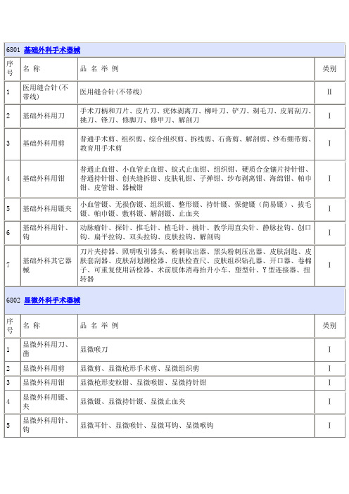
Ⅱ Ⅰ
骨接合用金属钛缝线
Ⅱ
钢针螺钉定位架、定位外套管、骨锤、快换丝锥套、张力器、持针镊、测深
8
矫形(骨科)外 器、攻螺丝器、人工股骨假体加压固定器、CD 棒推进器、CD 钩推进器、拔 科用其它器械 钉器、扳手、槌骨器、假体打入器、导向器、拔出器、骨旋凿保护器、骨压
缩器、骨折固定夹、加压器、间隔器、髋关节成形钻柄、髋关节帽打孔器、
Ⅰ
4 基础外科用钳
普通止血钳、小血管止血钳、蚊式止血钳、组织钳、硬质合金镶片持针钳、 普通持针钳、创夹缝拆钳、皮肤轧钳、子弹钳、纱布剥离钳、海绵钳、帕巾 Ⅰ 钳、皮管钳、器械钳
5
基础外科用镊夹
小血管镊、无损伤镊、组织镊、整形镊、持针镊、保健镊(简易镊)、拔毛 镊、帕巾镊、敷料镊、解剖镊、止血夹
Ⅰ
6
基础外科用针、 动脉瘤针、探针、推毛针、植毛针、挑针、教学用直尖针、静脉拉钩、创口
钩
钩、扁平拉钩、双头拉钩、皮肤拉钩、解剖钩
Ⅰ
刀片夹持器、照明吸引器头、粉刺取出器、黑头粉刺压出器、皮肤刮匙、皮
7
基础外科其它器 肤套刮器、皮肤刮划测检器、皮肤检查尺、皮肤组织钻孔器、开口器、卷棉
械
子、可重复使用活检器、术前肢体消毒抬升小车、塑型针、Y 型连接器、扭
Ⅰ
转器
6802 显微外科手术器械
序 号
序 号
名称
品名举例
类别
1
烧伤(整形)用 刀、凿
辊轴取皮刀、鼻手术刀、鼻骨凿、指骨凿
Ⅰ
3
烧伤(整形)用 钳
颌骨夹持钳、肌腱夹持钳、肌腱穿刺钳、软骨塑型钳
Ⅰ
4
烧伤(整形)用 镊、夹
整形镊、皮肤镊、眼睑镊、唇夹
pm60粉末冶金高速钢成分

pm60粉末冶金高速钢成分
PM60粉末冶金高速钢是一种高性能的刀具材料,具有优异的耐磨性和耐热性能。
它由粉末冶金工艺制成,成分设计精确,包含以下主要成分:
1. 钨(W),提高了高速钢的硬度和耐磨性,使刀具具有较好的切削性能和耐磨性。
2. 钼(Mo),提高了高速钢的热硬化能力和抗变形能力,使刀具在高温下依然保持较好的硬度和刚性。
3. 铬(Cr),提高了高速钢的耐腐蚀性能和耐热性,延长了刀具的使用寿命。
4. 钒(V),提高了高速钢的强度和耐磨性,使刀具能够在高速切削时保持稳定的刀具形状和尺寸。
5. 碳(C),控制了高速钢的硬度和强度,使刀具具有良好的切削性能和耐磨性。
PM60粉末冶金高速钢以其优异的性能被广泛应用于刀具制造、汽车零部件加工、航空航天等领域,为工业生产提供了可靠的切削工具。
其精确的成分设计和优秀的性能使其成为现代制造业中不可或缺的材料之一。
3M Cut-Resistant Gloves Product Guide

Tactility Dexterity
1-5
1-5
NFD15
Light Task Plus II™ - White Dyneema® seamless liner with white polyurethane palm coating - sizes 6XS to 11XXL
4
2
4
2
NFD15B
Light Task Plus II Black™ - Gray Dyneema® seamless liner with black bipolymer palm coating - sizes 6XS to 11XXL
OSHA 29 CFR Part 1910 - Subpart 1 Personal Protective Equipment 1910.138: Hand Protection, states that employers shall select and require employees to use appropriate hand protection when employees' hands are exposed to hazards. This guide provides relative performance data for different types of general purpose and cut resistant gloves and is intended to help users select a glove that is suited to their applications. However, test data gathered in a laboratory does not necessarily reflect real-world conditions in the work place and therefore, hand protection selection and worker safety remains the responsibility of the employer.
ASP-60粉末钢ASP60模具钢ASP-60材料热处理硬度
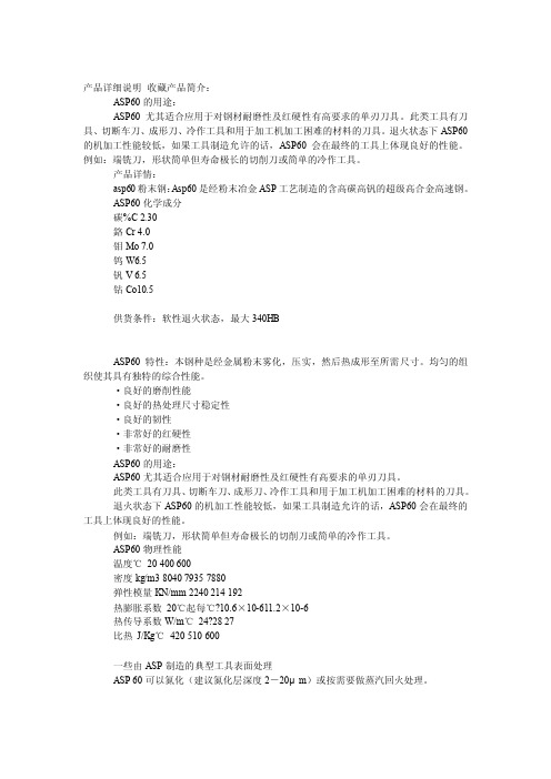
产品详细说明收藏产品简介:ASP60的用途:ASP60尤其适合应用于对钢材耐磨性及红硬性有高要求的单刃刀具。
此类工具有刀具、切断车刀、成形刀、冷作工具和用于加工机加工困难的材料的刀具。
退火状态下ASP60的机加工性能较低,如果工具制造允许的话,ASP60会在最终的工具上体现良好的性能。
例如:端铣刀,形状简单但寿命极长的切削刀或简单的冷作工具。
产品详情:asp60粉末钢:Asp60是经粉末冶金ASP工艺制造的含高碳高钒的超级高合金高速钢。
ASP60化学成分碳%C 2.30鉻Cr 4.0钼Mo 7.0钨W6.5钒V 6.5钴Co10.5供货条件:软性退火状态,最大340HBASP60特性:本钢种是经金属粉末雾化,压实,然后热成形至所需尺寸。
均匀的组织使其具有独特的综合性能。
·良好的磨削性能·良好的热处理尺寸稳定性·良好的韧性·非常好的红硬性·非常好的耐磨性ASP60的用途:ASP60尤其适合应用于对钢材耐磨性及红硬性有高要求的单刃刀具。
此类工具有刀具、切断车刀、成形刀、冷作工具和用于加工机加工困难的材料的刀具。
退火状态下ASP60的机加工性能较低,如果工具制造允许的话,ASP60会在最终的工具上体现良好的性能。
例如:端铣刀,形状简单但寿命极长的切削刀或简单的冷作工具。
ASP60物理性能温度℃20 400 600密度kg/m3 8040 7935 7880弹性模量KN/mm 2240 214 192热膨胀系数20℃起每℃?10.6×10-611.2×10⁻⁶热传导系数W/m℃24?28 27比热J/Kg℃420 510 600一些由ASP制造的典型工具表面处理ASP 60可以氮化(建议氮化层深度2-20μm)或按需要做蒸汽回火处理。
软性退火加热至850-900℃,以10℃/小时慢冷至700℃,硬度最高值为340HBASP60硬度:HRC66-68ASP60密度:8.25g/cm3出货状态:已热处理和未热处理两种,六面研磨库存规格:4mm-70mm,长宽不限,可订做。
- 1、下载文档前请自行甄别文档内容的完整性,平台不提供额外的编辑、内容补充、找答案等附加服务。
- 2、"仅部分预览"的文档,不可在线预览部分如存在完整性等问题,可反馈申请退款(可完整预览的文档不适用该条件!)。
- 3、如文档侵犯您的权益,请联系客服反馈,我们会尽快为您处理(人工客服工作时间:9:00-18:30)。
CUT-60材料清单
版本:A 修改码:0 编号:WS/02-CUT-60 焊机事业部逆变组
CUT-60上板材料清单 序号 物料编码 1 2 3 4 5 6 7 8 9 10 11 12 13 14 15 16 17 零件名称 场效应管 电流互感器 聚脂薄膜电容 聚脂薄膜电容 校正电容 高压瓷片电容 高压瓷片电容 水泥电阻 碳膜电阻 碳膜电阻 成品驱动板 插 插 插 座 座 座 规格型号 K2837 EE-25 200:0 475/250V 225/630V 105 471/2KV 472/3KV 10W47R 1/4W 2.4K 1/4W 6.8R 单位 个 个 个 个 个 个 个 个 个 个 块 个 个 个 米 根 数量 20 1 4 3 2 4 2 4 1 24 1 1 1 2 1 0.05 1 图纸编号 备注
SD-PCB-Q02-A0
VH—04 XH—07(6) XH—09(8)
线路板 电流互感器线 黄绿线
SD-PCB-S05-AO
1.5m㎡ ¢1.0 0.2米
序号 物料编码 1 2 3 4 5 6 7 8 9 10
零件名称 驱动变压器 校正电容 碳膜电阻 碳膜电阻 二极管 稳压二极管 绝缘板 套管 PCB 插针
图纸编号
备注
15 16 17 18 19 20 21 22 23 24 25 26 27 28 29 30 31 32 33
碳膜电阻 碳膜电阻 碳膜电阻 碳膜电阻 碳膜电阻 碳膜电阻 碳膜电阻 碳膜电阻 碳膜电阻 二极管 发光二极管 稳压二极管 三极管 三极管 IC IC 可控硅 光耦 线路板
1/8W2K 1/8W5.1K 1/8W6.2K 1/8W8.2K 1/8W10K 1/8W20K 1/8W22K 1/8W51K 1/8W220K IN4148 ¢3红色 15V C8050 C8550 CA3140 SC3525 MZ100-6 PC817
图纸编号 外加工 自裁
备注
所有机器通用 外加工 外加工
7 8 9 10 11 12 13 14 15 16 17 18 19 20 21 22 23 24 25 26 27 28 29 30 31 32 33 34 35 36 37 38 39 40 41 42 43 44 45 46 47 48 49 50 51
主控制绝缘板 电源底版绝缘板 竖粱 主控制板固定片 横粱 上挡风板 左右侧挡风板 下挡风板 机底 机盖 前面板 控制变压器 电抗器 整流桥 焊接电缆耦合装置 快速插座 电位器 电位器 小型断路器 短路器固定片 数显表 灯座 红灯 防水拉不脱 冷却风机 风机网罩 分流器 输出扁铜 铜接头 塑料空心支柱 橡皮底柱 导热硅脂 扳手 电位器旋钮 扎带 B型手柄 纸箱 包装塑料袋 说明书 绝缘自干漆 包装带 通用橡套软电缆电 线 保修卡 装箱清单 合格证
CUT-60中板材料清单 规格型号 单位 EER43 9∶4 D92-02 1W22R 1W2K 14D151 221/1KV 471/1KV Ø2.5× 42.8 Ø2.5× 58.3 Ø2.5× 31.0 Ø2.5× 72.3 Ø2.5× 118.5 Ø2.5× 164.8 ¢0.4 16*18 VH-02 VH-03(2) 个 个 个 个 个 个 个 个 个 个 个 个 个 个 个 个
数量 4 16 16 1 1 16 2 11 5 1 1 1 1 4 1 1 1 1 数量 3 1 1 2 2 6 1 1 1 1 2 3 1 3
图纸编号
备注
SD-PCB-Z08-A0 个 BR-B2D 95℃ 250V 6A 个 CUT-60小控制板清单 规格型号 单位 102 个 472 个 501 个 222 个 103 个 104 个 684/35V 个 475/35V 个 225/35V 个 1/4W100R 个 1/8W51R 个 1/8W100R 个 1/8W680R 个 1/8W1K 个
零件名称 二极管 整流二极管 滤波电感 可调电阻 可调电阻 可调电阻 可调电阻 I C 三极管 发光二极管 场效应管
CUT-60主控制板清单(2) 规格型号 单位 数量 FR104 D92-02 30uH 3296 20K正调 3296 10K正调 3296 2K正调 3296 100K正调 UC3843 8050 ¢5红色 IRFZ24 个 个 个 个 个 个 个 个 个 个 个 2 1 1 1 1 1 2 1 3 1 3
大驱动模块 规格型号 单位 EI-33 16:8 224J/100V 1/4W 3K 1W 5.1R IN4148 1/2W5.1V 100× 45 ¢6 0.06米 0.63 个 个 4 1 1 1 36
图纸编号
备注
SD-PCB-Q02-A0
个 个 个 个 个 个 个 个 个 个 个 个 个 个 个 个 个 个 块
4 3 2 1 6 2 1 1 1 5 2 3 6 2 1 1 1 1 1
SD-PCB-K02-A0
序号 物料编码 1 2 3 4 5 6 7 8 9 10 11
零件名称 电解电容 继电器 碳膜电阻 热敏电阻 插座 插座 插座 插座 插座 插片 线路板
图纸编号
备注
PCB板 瓷片电容 磁环 直插座XH 聚酯电容
SD-PCB-H02-A0 472/3KV 18X11X5 VH-03 104
块 个 个 个 个
1 2 1 1 1
序号 物料编码 1 2 3 4 5 6
零件名称 散热器 铜螺柱 绝缘布 压块 塑料螺柱 上绝缘板
CUT-60装加工件材料清单(1) 规格型号 单位 数量 100*49*29*230长 3× 8+6 30× 195 38× 10 3× 8+6 105× 220 对 个 块 块 个 块 1 8 4 18 4 1
块 块 根 套 根 块 块 块 个 个 个 个 个 个 套 套 个 个 个 个 个 套 个 个 个 个 个 套 个 个 个 条 个 个 根 个 个 条 本 斤 卷
108× 60 120× 110 270 1左、1右、1隔板 441mm 126× 12 38× 120× 52 98× 20 50× 450× 200× 280 480× 201× 283 281× 200 30W/双15V JTX-2128 55UH S25VB60 DKJ16-25 16-25 2W1K 2W10K DZ47-60 300A 75mV ¢5 ¢5 PG16 P/N 15050HSL ¢150 300A 75mV 2*20 16—8 L8 中号 M6 自制 3×100 中文 中文
个 个 个 个 个 个 个 个 个 个 个 个 个 个 个 个 个 个 个 个 个 个 个 个 个 个 个 个 个 个 个 个 个
1 1 2 3 2 3 1 1 1 1 1 4 2 6 1 3 1 1 2 2 1 1 1 1 1 1 1 1 1 7 2 1 1
序号 物料编码 37 38 39 40 41 42 43 44 45 46 47
CUT-60 底板材料清单 规格型号 单位 470uF/450V 30A/24V 1W150K 10D-20 VH-02 VH-03 VH-05 VH-07 VH-10 6.3 个 个 个 个 个 个 个 个 个 个 个
数量 6 1 4 2 1 1 1 1 3 3 1
图纸编号
备注
SD-PCB-D06-A0
个 个 个 个 个 个 个 个 个 个 个 个
1 3 1 1 1 1 1 2 1 2 1 1
13 14 15 16 17 18 19 20 21 22 23 24 25 26 27 28 29 30 31 32 33 34 35 36 37 38 39 40 41 42 43
水泥电阻 热敏电阻 聚酯电容 聚酯电容 聚酯电容 瓷片电容 瓷片电容 瓷片电容 电解电容 电解电容 升压变压器 快速二极管 快速二极管 高压二极管 二极管 二极管 稳压二极管 稳压二极管 三极管 三极管 三极管 场效应管 引弧板PCB 磁环电感 继电器 插片 放电嘴 直插座XH 直插座VH 直插座VH 直插座VH
序号 物料编码 1 2 3 4 5 6 7 8 9 10 11 12
零件名称
CUT-60 引弧板材料清单 规格型号 单位
数量
图纸编号
备注
碳膜电阻 碳膜电阻 碳膜电阻 碳膜电阻 碳膜电阻 碳膜电阻 碳膜电阻 碳膜电阻 碳膜电阻 碳膜电阻 碳膜电阻 碳膜电阻
1/4W 100K 1/4W 10K 1/4W 10Ω 1/4W 15K 1W 1K 1W 2K 1/4W 2K 1/4W 43K 1/4W 5.1K 5W 220K 5W 1K 1/4W 6.8K
序号 物料编码 1 2 3
零件名称 校正电容 校正电容 校正电容
CUT-60主控制板清单(1) 规格型号 单位 数量 103 104 105 个 个 个 4 12 1
图纸编号
备注
4 5 6 7 8 9 10 11 12 13 14 15 16 17 18 19 20 21 22 23 24 25 26 27 28 29 30 31 32 33 34 35 36
个 个 个 个 个 个 个 个 个 个 个 个 个 个 个 个 个 个 个 个 个 个 块 个 只 个 个 个 个 个 个
1 2 2 4 1 1 4 3 1 2 1 1 1 4 3 1 1 1 1 2 1 1 1 1 1 2 2 2 4 1 1
序号 物料编码 1 2 3 4 5
零件名称
CUT-60 手控开关板材料清单 规格型号 单位 数量
零件名称 变压器 快恢复二极管 碳膜电阻 碳膜电阻 压敏电阻 瓷片电容 瓷片电容 铜条 铜条 铜条 铜条 铜条 铜条 铜片 插座 插座 线路板 热保护器 零件名称 涤纶电容 涤纶电容 瓷片电容 瓷片电容 校正电容 校正电容 胆电解电容 胆电解电容 胆电解电容 碳膜电阻 碳膜电阻 碳膜电阻 碳膜电阻 碳膜电阻
