MSS SP-6-2007 管法兰以及阀门和管件端法兰的接触面标准精度
MSS标准译文
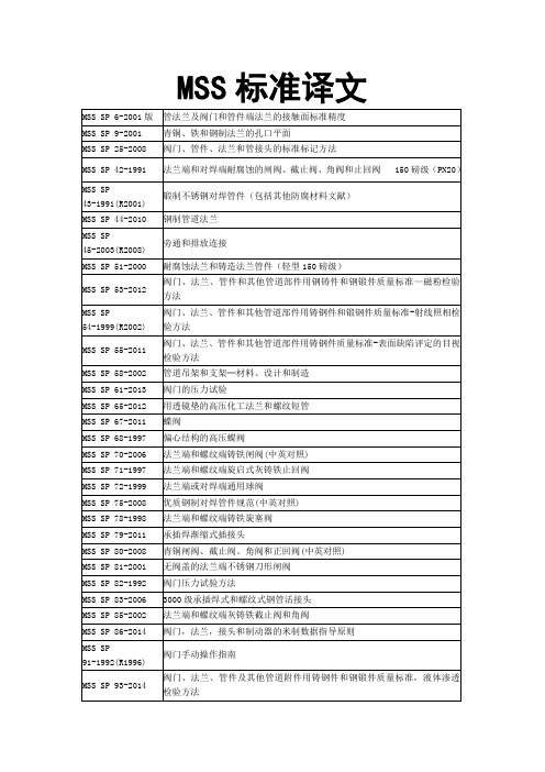
MSS SP 6-2001版
管法兰及阀门和管件端法兰的接触面标准精度
MSS SP 9-2001
青铜、铁和钢制法兰的孔口平面
MSS SP 25-2008
阀门、管件、法兰和管接头的标准标记方法
MSS SP 42-1991
法兰端和对焊端耐腐蚀的闸阀、截止阀、角阀和止回阀150磅级(PN20)
弹簧加载中心导向的灰铸铁和球墨铸铁Байду номын сангаас线止回阀
MSS SP 126-2000
弹簧加载中心导向的钢制管线止回阀
MSS SP 134-2012
对低温阀门及其阀体/阀盖加长体的要求
QQ:416711838
法兰端或对焊端通用球阀
MSS SP 75-2008
优质钢制对焊管件规范(中英对照)
MSS SP 78-1998
法兰端和螺纹端铸铁旋塞阀
MSS SP 79-2011
承插焊渐缩式插接头
MSS SP 80-2008
青铜闸阀、截止阀、角阀和正回阀(中英对照)
MSS SP 81-2001
无阀盖的法兰端不锈钢刀形闸阀
MSS SP 98-2012
阀门、消防栓和管件的内部保护性涂层
MSS SP 100-2002
核用隔膜阀弹性隔膜的鉴定要求
MSS SP108-2002
弹性密封的铸铁偏心旋塞阀
MSS SP 112-1993
评定表面粗糙底的质量标准目视和触感方法
MSS SP 117-2006
截止阀和闸阀的波纹管密封件
MSS SP 118-2002
阀门的压力试验
MSS SP 65-2012
用透镜垫的高压化工法兰和螺纹短管
MSS SP 67-2011
阀门规范列表[1]
![阀门规范列表[1]](https://img.taocdn.com/s3/m/35b1f6df08a1284ac850437b.png)
工业阀门——部分回转执行器附件 工业阀门——铸铁止回阀 工业阀门——法兰端阀门的保护罩 法兰及其连接件——法兰用垫片(英制) 第 1 篇 带或不带填充物的非金属平垫片 法兰及其连接件——法兰用垫片(英制)第 2 篇 钢制法兰用螺旋缠绕垫片 法兰及其连接件——法兰用垫片(英制) 第 3 篇 非金属聚四氟乙烯(PTFE)包覆式垫片 法兰及其连接件——法兰用垫片(英制) 第 4 篇 钢制法兰用带或不带填充物的波形、平或齿形金属垫片 法兰及其连接件——法兰用垫片(英制)第 5 篇 钢制法兰用金属环连接垫片 工业阀门——化工和石油化工加工工业用阀门要求和试验 工业阀门——确定操作元件尺寸的方法 工业阀门——钢制阀门的对焊端 阀门——钢制阀门的承插焊端 工业阀门——对焊端阀门的(端-端和中心-端)结构长度 工业阀门——金属材料制成的隔膜阀 石油天然气工业——管线传输系统——海底管线阀
标准名称 通用工业阀门标记 工业阀门-法兰连接管道系统用金属阀门的结构长度第 1 篇米制系列阀门 工业阀门-法兰连接管道系统用金属阀门的结构长度第 1 篇英制系列阀门 工业阀门-金属蝶阀 阀门术语第 1 篇阀门类型的定义 阀门术语第 2 篇阀门部件的定义 法兰及其连接-管理、阀门、管件和附件用圆法兰(米制系列)第 2 篇铸铁法 兰 法兰及其连接-法兰用垫片尺寸(米制)第 1 篇带或不带内衬的非金属平垫片 法兰及其连接-法兰用垫片尺寸(米制)第 2 篇钢法兰用缠绕式垫片 法兰及其连接-法兰用垫片尺寸(米制)第 3 篇非金属 PIFE 包覆垫片 法兰及其连接-法兰用垫片尺寸(米制)第 4 篇钢法兰用波形、平面或齿形金 属和填充金属垫片 管道、阀门和管件(英制)用圆法兰第 3 篇钢、铸铁和铜合金法兰第 3.1 篇 钢法兰 管道、阀门和管件(英制)用圆法兰第 3 篇钢、铸铁和铜合金法兰第 3.2 篇 铸铁法兰 管道、阀门和管件(英制)用圆法兰第 3 篇钢、铸铁和铜合金法兰第 3.3 篇 铜合金和组合法兰 石油、石化及相关工业用(法兰和对焊链接的)钢止回阀 石油、石化及相关工业用(法兰和对焊链接的)钢截止阀、截止止回阀和止 回阀 液动系统用阀第 1 篇压差/流量特性测定方法 液动系统用阀第 1 篇性能测定方法 管道、阀门和管件(米制)用圆法兰第 3 篇钢、铸铁和铜合金法兰第 3.1 篇 钢法兰 管道、阀门和管件(米制)用圆法兰第 3 篇钢、铸铁和铜合金法兰第 3.2 篇 铸铁法兰技术条件 管道、阀门和管件(米制)用圆法兰第 3 篇钢、铸铁和铜合金法兰第 3.3 篇 铜合金和组合法兰 铸铁闸阀 通用铸铁(平板)闸阀 通用铸铁截止阀和截止止回阀 通用铸铁止回阀 铜合金截止阀、截止止回阀、止回阀及闸阀 隔膜阀 钢制(平板)闸阀 铸铁旋塞阀 通用铸铁和碳钢球阀 钢制截止阀、截止止回阀和升降式止回阀 供水系统用铸铁闸阀 工业阀门-多回转阀门驱动装置的连接 石油、石化及相关工业用钢制球阀
MSS SP标准最新目录-201403
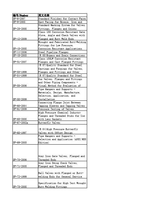
SP-108-2002 SP-109-1997
SP-110-1996 SP-111-2001 SP-112-1999 SP-113-2001 SP-114-2007 SP-115-2006 SP-116-2003 SP-117-2006
SP-118-2007 SP-119-2003
SP-120-2006 SP-121-2006 SP-122-2005 SP-123-1998 SP-124-2001
SP-72-1999
SP-75-2008
SP-78-2005a SP-79-2009 SP-80-2008 SP-81-2006a SP-82-1992 SP-83-2006 SP-84
Gray Iron Plug Valves, Flanged and Threaded Ends Socket-Welding Reducer Inserts Bronze Gate, Globe, Angle and Check Valves Stainless Steel, Bonnetless, Flanged, Knife Gate Valves
Class 3000 Steel Pipe Unions, Socket-Welding and Threaded 承口焊连接和螺纹连接钢制阀门
Gray Iron Globe & Angle Valves, SP-85-2002 Flanged and Threaded Ends Guidelines for Metric Data in Standards for Valves, Flanges, SP-86-2002 Fittings and Actuators SP-88-1993 (R 01) Diaphragm Valves Guidelines for Manual Operation of SP-91-2009 Valves SP-92-1999 MSS Valve User Guide Quality Standard for Steel Castings and Forgings for Valves, Flanges, and Fittings and Other Piping Components - Liquid Penetrant SP-93-2008 Examination Method SP-94-2008 Quality Std for Ferritic and SP-95-2006 Swage(d) Nipples and Bull Plugs (R 05)Guidelines on Terminology for SP-96-2001 Valves and Fittings Integrally Reinforced Forged Branch SP-97-2006 Outlet Fittings - Socket Welding, (R 05)Protective Coatings for the Interior of Valves, Hydrants, and SP-98-2001 Fittings SP-98-2001(R2005) 阀门、消防栓和管件的内部保护性涂层 SP-99-1994 (R 05)Instrument Valves Qualification Requirements for Elastomer Diaphragms for Nuclear SP-100-2002 Service Diaphragm Valves (R 01)Part-Turn Valve Actuator SP-101-1989 Attachment - Flange and Driving (R 01)Multi-Turn Valve Actuator Attachment - Flange and Driving Component Dimensions and SP-102-1989 Performance haracteristics Wrought Copper Solder Joint SP-104-2003 Pressure Fittings (R 05)Instrument Valves for Code SP-105-1996 Applications Cast Copper Alloy Flanges and SP-106-2003 Flanged Fittings, Class 125, 150
法兰标准
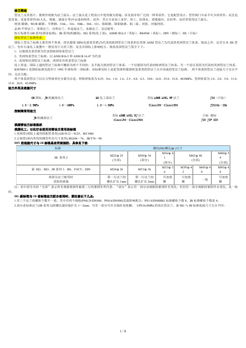
法兰简述管法兰及其垫片、紧固件统称为法兰接头。
法兰接头是工程设计中使用极为普遍、涉及面非常广泛的一种零部件。
它是配管设计、管件阀门中必不可少的零件,而且也是设备、设备零部件(如人孔、视镜、液面计等)中必备的构件。
此外,其它专业如工业炉、热工、给排水、采暖通风、自控等,也经常使用法兰接头。
材质:锻钢、WCB碳钢、不锈钢、316L、316、304L、304、321、铬钼钢、铬钼钒钢、钼二钛、衬胶、衬氟材质。
品种:平焊法兰、带颈法兰、对焊法兰、环连接法兰、承插法兰、及盲板等。
执行标准有GB系列(国家标准)、JB系列(机械部)、HG系列(化工部)、ASME B16.5(美标)、BS4504(英标)、DIN(德标)、JIS(日标)国际管法兰标准体系:国际上管法兰标准主要有两个体系,即以德国DIN(包括原苏联)为代表的欧洲管法兰体系和以美国ANSI管法兰为代表的美洲管法兰体系。
除此之外,还有日本JIS管法兰,但在石油化工装置中一般仅用于公用工程,而且在国际上影响较小。
现将各国管法兰简介于下:1,以德国及原苏联为代表的欧洲体系管法兰2,美洲体系管法兰标准,以ANSI B16.5和ANSI B 16.47为代表3,英国和法国管法兰标准,两国各有两套管法兰标准综上所述,国际上通的管法兰标准可概括为两个不同的,且不能互换的管法兰体系:一个以德国为代表的欧洲管法兰体系;另一个是以美国为代表的美洲管法兰体系。
IOS7005-1是国际标准化组织于1992年颁布的一项标准,该标准实际上是把美国和德国两套系列的管法兰合并而成的管法兰标准。
两个体系的管法兰连接尺寸安全不同,无法互配:两个体系的管法兰以压力等级来区分最为合适,即欧洲体系为0.25、0.6、1.0、1.6、2.5、4.0、6.3、10.0、16.0、25.0、32.0、40.0MPa,美洲体系为1.0、2.0、5.0、11.0、15.0、26.0、42.0MPa法兰外形及连接尺寸GB国标、JB机械部法兰HG化工部法兰美标ASME/ANSL RF法兰JIS(日标)1.0~2.5MPa 4.0~16MPa 1.0~4.0MPa Class150~Class1500 JIS10k~20k控制阀常用法兰JB机械部法兰美标ASME/ANSL RJ法兰日标德标Class150~Class2500 JIS JIP DIN我国管法兰标准现状我国化工、石化行业使用的管法兰常用的标准1.英制管(国际上通用的配管系列) GB 9112~9125、SH 34062.公制管(国内常用的钢管外径尺寸系列) HGJ44~76、JB/T74~90注:表中括号内的“全部”表示所有规格紧固件被第二行的紧固件所代替。
阀门通用技术要求
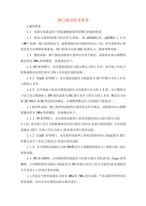
阀门通用技术要求1通用要求1.1本部分条款适用于招标辅机配套供货阀门的通用要求1.2投标方提供的阀门均应符合国标,或ANSlB16.34、ANSIB31.1以及ΛWWΛ标准。
阀门选用的压力、温度等级应符合相应的运行工况,符合系统设计要求及有关法规和标准要求。
阀门的设计应按ANSl标准压力一温度等级考虑,1.3强度试验:阀门强度试验的计量单位应符合规定,试验值应加大圆整到最近的O.IMPa的倍数值。
具体规定如下:1.3.1PN系列阀门,水压强度试验压力按公称压力的1.5倍;也可将工作压力转换成相对应的公称压力取1.5倍进行强度试验。
1.3.2CIaSS系列阀门,水压强度试验压力按温度为38℃时最大允许工作压力值的1.5倍。
1.3.3安全阀进口的水压强度试验压力应按设计压力的1.5倍,出口侧按出口法兰压力级别的1.5PN或在温度为38C最大允许工作压力的1.5倍。
整定压力应按JB/T9624或GB/T12243的规定,并调整到整定压力范围的下限值出厂。
1.4密封性试验:阀门密封性试验的计量单位应符合规定,试验值应加大圆整到最近的0.1MPa的倍数值。
具体规定如下:1.4.1PN系列阀门,水压密封试验和上密封试验时的压力按公称压力的1.1倍;也可将工作压力转换成相对应的公称压力取Ll倍进行密封试验;当介质温度超过425℃,可按工作压力的1.25倍进行阀门密封试验。
1.4.2ClaSS系列阀门,水压密封试验和上密封试验时的压力按温度为38℃时最大允许工作压力值的Ll倍进行密封试验。
1.4.3安全阀密封试验压力按90%整定压力或最低回座压力(取较小值)进行密封试验。
1.4.4PN系列蝶阀、止回阀的密封试验压力应按公称压力的L0倍;Claas系列蝶阀、止回阀的密封试验压力按温度为38C时最大允许工作压力值的LO倍或按设计压差的1.1倍进行密封试验。
1.4.5低压气密封试验压力按0.4MPa~0.7MPa进行试验。
mss法兰标准
mss法兰标准
MSS(美国阀门及配件工业制造商标准化协会)的SP-6-2017标准是关于管法兰以及阀门和管件端法兰的接触面标准精度的规范。
这个标准惯例是在MSS技术委员会102(主要的)、110、201和MSS统筹委员会的一致同意下制定的,阐述了最低要求,并将作为制造商、用户和公众通用惯例的基础。
请注意,现有的MSS标准惯例本身并不排斥从事生产、销售或使用不符合本标准惯例的产品。
只有当适用的规则、规范、销售合同或国际法中引用了本标准惯例时,才强制要求符合本标准惯例。
MSS没有权利,也不承担实施或证明与本标准符合的义务。
任何符合本标准惯例要求的证明或说明不可归咎于MSS,仅是证明者和说明者的责任。
如需更多信息,建议直接查阅MSS官方文件或咨询相关专业人士。
最新阀门相关标准目录

121
CB/T 4337-2013
船用铝质通风法兰
122
JB/T 8692-2013
烟道蝶阀
123
JB/T 2205-2013
减压阀结构长度
124
JB/T 8531-2013
阀门手动装置技术条件
125
JB/T 5299-2013
液控止回蝶阀
126
JB/T 8691-2013
无阀盖刀形闸阀
103
CB/T 3192-2013
外螺纹蒸汽青铜直角安全阀
104
SH/T 3401-2013
石油化工钢制管法兰用非金属平垫片
105
SH/T 3402-2013
石油化工钢制管法兰用聚四氟乙烯包覆垫片
106
SH/T 3403-2013
石油化工钢制管法兰用金属环垫
107
SH/T 3404-2013
石油化工钢制管法兰用紧固件
78
GB/T 13819-2013
铜及铜合金铸件
79
GB 9948-2013
石油裂化用无缝钢管
80
GB 13296-2013
锅炉、热交换器用不锈钢无缝钢管
81
GB/T 29751-2013
管路补偿接头选用和安装要求
82
GB/T 10-2013
沉头方颈螺栓
83
GB/T 11-2013
沉头带榫螺栓
84
GB/T 12-2013
水管锅炉第7部分:安全附件和仪表
47
GB/T 16507.8-2013
水管锅炉第8部分:安装与运行
48
GB/T 16507.8-2013
水管锅炉第8部分:安装与运行
我国的法兰标准体系

我国的法兰标准体系中国的法兰标准大体分为管法兰标准和压力容器法兰标准。
常用管法兰标准有国家标准(GB)、化工行业标准(HG)、机械行业标准(JB)、石化行业标准(SH)以及船用法兰标准。
这些标准自成体系,有各自的温度压力表、密封面尺寸和接管尺寸,有的标准之间能够互换,有的标准之间相互之间互换性差,有些甚至不能配套使用。
强制性标准与推荐性标准在上世纪90年代中期之前,大多数国家标准和行业标准都没有区分强制性标准和推荐性标准。
后来根据标准化法开始区分强制性标准和推荐性标准。
强制性标准是在一定范围内通过法律、行政法规等强制性手段实施的标准。
具有法律属性。
强制性标准一经颁布,就必须执行。
否则,造成恶劣后果和重大损失的单位和个人,应承担法律责任,并受到经济制裁。
强制性标准是指保障人体健康和人身财产安全的标准,以及法律、行政法规强制执行的标准。
强制性标准可分为全文强制性和条款强制性两种形式:当标准的所有技术内容都需要强制性时,为全文强制性;当标准中的某些技术内容需要强制执行时,它是以强制性条文的形式出现的。
推荐性标准是指在生产和使用方面,通过经济手段或市场调节自愿采用的标准。
一旦被接受和采用,或被双方接受,推荐标准就成为各方必须共同遵守的技术依据,具有法律约束力。
我国现行的国家标准和工业法兰标准大多是推荐性标准。
我国法兰标准体系主要有四种。
国家法兰标准法兰标准实际上是指管法兰标准,更具体一点,是指钢制管法兰标准。
钢制管法兰国家标准,自1989年版实施以后,曾于2000年修订过一次,形成了GB/T 9112〜9124—2000钢制管法兰系列标准。
随者技术的不断发展和闰外标准的修订,我国也对2000年版标准进行了修改与完善,于2010年发布现行钢制管法兰系列标准GB/T 9112〜9124—2010,并于2011年10月起实施。
按现行标准《钢制管法兰类型与参数》GB/T 9112—2010的规定,国标钢制管法兰的类型分为两类,一类是PN标记法兰(即欧洲体系法兰或欧标法兰),在我国最为常用。
美国阀门和管件工业制造商标准化协会标准
美国阀门和管件工业制造商标准化协会标准1、MSS SP-6-07管法兰以及阀门和管件端法兰的接触面标准粗糙度2、MSS SP-9-08青铜、铁和钢制法兰的孔口平面3、MSS SP-25-1998阀门、管件、法兰和管接头的标准标记方法4、MSS SP-42-2004150磅级,法兰和对焊连接耐腐蚀闸阀、截止阀、角阀和止回阀5、MSS SP-44-2010钢制管道法兰6、MSS SP-45-2003旁通和排放连接7、MSS SP-51-2003轻型150磅级耐腐蚀铸造法兰和法兰管件8、MSS SP-53-1999(R2002)阀门、法兰、管件及其他管道附件用钢铸件和钢锻件质量标准磁粉检验方法9、MSS SP-55-2006阀门、法兰、管件及其它管路附件的铸钢件质量标准用于表面缺陷评定的目视检验法10、MSS SP-61-2009钢阀门的压力试验13、MSS SP-67-2002aButterfly Valves 蝶阀14、MSS SP-68-1997(R2004)偏心结构的高压蝶阀15、MSS SP-70-2006法兰端和螺纹端灰铸铁闸阀16、MSS SP-71-2005法兰端和螺纹端旋启式灰铸铁止回阀17、MSS SP-72-1999法兰端或对焊端的通用球阀18、MSS SP-78-1998法兰和螺纹端铸铁旋塞阀19、MSS SP-79-2010承插焊缩径接头20、MSS SP-80-2008青铜闸阀、截止阀、角阀和止回阀21、MSS SP-81-2006不锈钢无阀盖法兰刀形闸阀22、MSS SP-82-1992阀门压力试验方法23、MSS SP-83-20063000磅级承插焊和螺纹连接钢管活接头24、MSS SP-85-2002法兰端和螺纹端连接的铸铁截止阀和角阀25、MSS SP-88-2010隔膜阀26、MSS SP-91-1992(R1996)阀门手动操作指南27、MSS SP-92-1987(R1992)MSS阀门用户指南28、MSS SP-93-1999(R2004)阀门、法兰、管件及其他管道附件用钢铸件和钢锻件质量标准液体渗透检验方法29、MSS SP-94-1999(R2004)阀门、法兰、管件及其它管路附件的铁素体、马氏体铸钢件质量标准超声波检验方法30、MSS SP-101-1989部份回转阀门驱动装置的连接法兰和驱动件的尺寸和工作特性31、MSS SP-102-1989多回转阀门驱动装置的连接法兰和驱动件的尺寸和工作特性32、MSS SP-108-2002弹性密封的铸铁偏心塞阀33、MSS SP-112-1993评定铸造表面粗糙度的质量标准目视和触感方法34、MSS SP-117-2006用于截止阀和闸阀的波纹管密封件35、MSS SP-118-2007法兰端、无法兰端、螺纹端和焊接端紧凑型钢制截止阀和止回阀(化工和石油精炼用)36、MSS SP-120-2006升降式阀杆(明杆)钢制阀门柔性石墨填料系统(设计要求)36、MSS SP-125-2010Gray Iron and Ductile Iron In-Line, Spring-Loaded, Center- Guided Check Valves。
美国阀门和管件工业制造商标准化协会(MSS)
3000磅级承插焊和螺纹连接钢管活接头 法兰和螺纹端连接的铸铁截止阀和角阀 隔膜阀 阀门手动操作指南 阀门用户指南 阀门、法兰、管件及其它管路附件用钢铸件和钢锻件质量标准液体检验方法 阀门、法兰、管件及其它管路附件的铁素体、马氏体铸钢件质量标准 超声波检验方法 部分回转阀门驱动装置的连接法兰和驱动件的尺寸和工作特性 多回转阀门驱动装置的连接法兰和驱动件的尺寸和工作特性 弹性阀座铸铁偏心塞阀 评定铸表面粗糙度和质量标准 目视和触感方法 用于截止阀和闸阀的波纹管密封件 紧凑型法兰、无法兰、螺纹和焊接连接钢制截止阀和止回阀(化工和石油精炼用) 手于升降杆钢制阀门的柔性石墨填料系统(设计要求)
MSS MSS MSS MSS MSS MSS MSS MSS MSS MSS MSS MSS MSS MSS
SP P SP SP SP SP SP SP SP SP SP SP SP SP
83-95 85-94 88-93 91-92 92-92 93-87 94-92 101-89 102-89 108-96 112-93 117-96 118-96 120-97
美国阀门和管件工业制造商标准化协会(MSS)
标 准 代 号 MSS SP 6-1990 MSS SP 9-1992 MSS SP 25-1993 MSS SP 42-1995 MSS SP 44-1991 MSS SP 45-1992 MSS SP 51-1995 MSS SP 53-1995 MSS SP 54-1995 MSS SP 55-2001 MSS SP 61-1992 MSS SP 65-1994 MSS SP 67-1995 MSS SP 68-1997 MSS SP 70-1990 MSS SP 71-1990 MSS SP 72-1992 MSS SP 78-1978 MSS SP 79-1992 MSS SP 80-1997 MSS SP 81-95 MSS SP 82-92 中 文 名 称 阀门和管件法兰连接端和管法兰密封面的表面粗糙度标准 铜墙铁壁、铁和钢制法兰螺纹孔锪端面尺寸 阀门、管件、法兰和管接头的标准标记法 150磅级法兰和对焊连接耐腐蚀的闸阀、截止阀、角式阀和止回阀 钢制管道法兰 旁通和排放孔的连接标准 轻型150磅级(CLASS 150 LW)耐腐蚀铸法兰和法兰管件 阀门、法兰、管件及其它管路附件用钢铸件和钢锻件质量标准磁粉检验方法 阀门、法兰、管件及其它管路附件用质量标准射线照相检验方法 阀门、法兰、管件及管路附件钢铸件质量标准用于表面缺陷评定的目视检验 钢制阀门压力试验 用透镜垫的高压比化工期法兰和螺纹短管 蝶阀 偏心结构的高压蝶阀 法兰和螺纹连接的铸铁闸阀 法兰和螺纹连接的铸铁旋启式止回阀 一般用法兰和对焊连接的球阀 法兰和螺纹端铸铁旋塞阀 承插焊缩径接头 铜制闸阀、截止阀、角式止回阀 不锈钢无阀盖法兰刀形闸阀 阀门压力试验方法
MSS SP-44-1996 钢制管道法兰

国外阀门标准 及相关标准汇编
钢制管道法兰
李信英 译 尹玉杰 校
中国阀门信息中心 沈阳阀门研究所
1
钢制管道法兰 MSS SP-44-1999 ( R2001 确认) 1 范围 1.1 概述 本标准包括法兰的压力-温度额定值、材料、尺寸、公差(以 ASME/ ANSI B16.5 为参照)、标记和试验。焊颈法兰可由锻钢制成,盲板法兰可由锻钢或钢板制成。 1.1.1 公称管径小于或等于 NPS10 的法兰,其尺寸要求应符合 ASME/ ANSI B16.5 的规定。若这些法兰符合本标准的所有其他要求,则认为该法兰符合本标准要求。 1.2 参照文献 ……
…
…
…
……
24 692.15 15.88 20.62 10.49 R77 692.15 25.40 31.75 17.30 R78
26 749.30 19.05
R93 749.30 28.58 34.93 19.81 R100
28 800.10 19.05 23.83 12.32 R94 800.10 31.75
4 热处理 4.1 标号大于或等于 F42 的各种磅级法兰以及 F36 的 400 及 400 磅级以上法兰应进行正火或淬 火加回火处理。
……
5 法兰设计 ……
6 标记 ……
7 加工面 7.1 法兰面的加工精度 (与 B16.5 中的要求基本一致) 7.2 凸面(应译为“突面” ) (与 B16.5 中的要求基本一致) 7.3 环连接 垫片凹面侧表面粗造度应不超过 63 微英寸。 7.4……
R101
30 857.25 19.05
R95 857.25 31.75 38.1 22.33 R102
阀门密封等级及选用
阀门密封等级及选用阀门是石油化工装置管道系统中的重要组成部件,其种类多、数量大,是装置中主要泄漏源之一,因此对阀门的泄漏要求至关重要。
阀门密封性能是指阀门各密封部位阻止介质泄漏的能力。
阀门的主要密封部位有:启闭件与阀座间的吻合面、填料与阀杆和填料函的配合、阀体与阀盖的连接处。
第一处的泄漏叫内漏,它直接影响阀门截断介质的能力和设备的正常运行。
后两处的泄漏叫外漏,即介质从阀内泄漏到阀外,它直接影响安全生产,造成工作介质损失和企业经济损失、环境污染,严重时会造成生产事故。
特别对于高温高压、易燃易爆、有毒或腐蚀性的介质,阀门的外漏根本是不允许的,因其所造成的后果比内漏更为严重,因此阀门必须具有可靠的密封性能,满足其使用工况对泄漏量的要求。
1我国阀门密封等级分类标准目前我国比较常用的阀门密封等级分类标准主要有以下两种。
1.1中国国家标准对阀门密封等级的分类国家标准GB/T13927--2008《工业阀门压力试验》。
1.2中国机械行业标准对阀门密封等级的分类机械行业标准JB/T 9092--1999《阀门的检验与试验》。
2国际上阀门密封等级分类标准目前围际上比较常用的阀门密封等级分类标准主要有以下五种。
2.1前苏联对阀门密封等级的分类为了按阀门的密封程度和规定的用途选择产品,按密封程度对阀门进行了分类,该分类的基本原则见表3和表4。
2.2国际标准化组织对阀门密封等级的分类国际标准化组织标准ISO5208--2008《工业阀门金属阀门的压力试验》。
2.3美国石油协会(APl)对阀门密封等级的分类美国石油协会标准API598--2004《阀门的检查和试验》。
2.4美国阀门和管件工业制造商标准化协会(MSS)对阀门密封等级的分类美国阀门和管件工业制造商标准化协会标准《钢制阀门的压力试验》MSS SP61---2003允许的阀门泄漏量要求如下:(1)在阀门密封副中有一个密封面使用塑料或橡胶的情况下,在密封试验的持续时间内应无可见泄漏。
进口阀门技术规格书中英文对照
进口阀门技术规格书Off-shore Valve Specification1.总则1.General1.1 概述1.1 Introduction本技术规格书是招标书的附件,用于中国石油化工集团公司南京化学工业有限公司大化肥装置原料改造项目(下简称项目)进口阀门的的设计、供货、试验和技术服务。
This specification is the appendix of the RFQ package. It covers the design, supply, testing and service for the off-shore valves for the NCIC FEEDSTOCK REVAMP PROJECT (hereafter called the “Project”) of China Petroleum and Chemical Corp. (SINOPEC).本技术规格书所列是对进口阀门的基本要求,并未对所有技术细节作出规范,也未完全陈述与之有关的规范和标准,且并不因此而减轻卖方在正确进行设计、保证系统可靠性和安全操作方面的责任。
This specification covers the basic requirements of the off-shore valves. It does not specify all the technical details and does not state all the codes and standards related therein. Seller is not relieved of his responsibilities in correct design, ensuring reliability for the system and safe operation.装置所在地:中国江苏省南京市六合区,南京化学工业有限公司Plant Location: Nanjing Chemical Industrial Co., Ltd. Liuhe District, Nanjing, Jiangsu Province, PRC.术语解释:Definitions:买方: 中国石化国际事业有限公司Buyer:China Petrochemical International Co.,Ltd.卖方:提供阀门的制造厂或代理公司Seller:The manufacturer or agent for the supply of the valves herein.。
控制阀的国际标准和认证概要
控制阀的国际标准和认证美国石油组织(API)规格6D(1994),管道阀的规格(闸板、柱塞、球和止回阀)598(1996),阀门检验和测试607(1993),软阀座纵向旋转阀的防火测试609(1997),凸耳式和对夹式蝶阀美国机械工程师学会(ASME)B16.1-1989,铸铁管道法兰和带法兰管件B16.4-1994,灰口铁螺纹管件B16.5-1996,管首法兰和带法兰管件(对于钢、镍基合金、和其它合金)B16.10-1992,阀门的端面至端面和尾端至尾端间距(见关于大部分控制阀的外形尺寸的ISA标准)B16.24-1991,铸铜合金管道法兰和带法兰管件B16.25-1997,对焊连接端B16.34-1996,阀门-法兰、螺纹和焊接连接端B16.42-1987,球墨铸铁管道法兰和带法兰管件B16.47-1996,较大直径的钢法兰(NPS26至NPS60)欧洲标准化委员会(CEN)欧洲工业阀门标准EN19(1992年12月),标记EN558-1(1995年10月),用在带法兰的管道系统里的金属阀门的端面至端面和中心线至端面间距一第1部分:PN代号阀门EN558-2(1995年3月),用在带法兰的管道系统里的金属阀门的端面至端面和中心线至端面间距-第2部分:ANSI代号阀门EN593,蝶阀(已批准但是日期未定)EN736-1(1995年6月),术语-第1部分:阀门类型定义EN736-2(1997年11月),术语-第2部分:阀门部件定义EN736-3,术语-第3部分,术语定义(准备中)EN1349,工业过程控制阀(准备中)EN1503-1,壳体材质-第一部分:钢(准备中)EN1503-2,壳体材质-第2部分:ISO钢(准备中)EN1503-3,壳体材质-第3部分:铸铁(准备中)EN1503-4,壳体材质-第4部分:铜合金(准备中)EN12266-1,阀门测试-第1部分:测试、测试过程和可接受的标准(准备中)EN12516-1,壳体设计强度-第1部分:钢质阀门的图表法(准备中)EN12516-2,壳体设计强度-第1部分:钢质阀门的计算法(准备中)EN12516-3,壳体设计强度-第1部分:实验法(准备中)EN12627,对焊端设计(准备中)EN12760,插焊端设计(准备中)EN12982,对焊端阀门的尾端至尾端间距(准备中)EN60534-1(1993年6月),第1部分:控制阀术语和一般性的考虑EN60534-2-1(1993年6月),第2部分:流通能力-第1节:在安装情况下不可压缩流体的阀门口径计算公式EN60534-2-2(1993年6月),第2部分:流通能力-第2节:在安装情况下可压缩流体的阀门口径计算公式EN60534-2-3(1993年6月),第2部分:流通能力-第3节:测试步骤EN60534-8-2(1993年6月),第8部分:关于噪声的考虑-第2节:由通过控制阀的液相流量产生的噪声的实验室测量EN60534-8-3(1996年2月),第8部分:关于噪声的考虑-第3节:控制阀气体动力学噪声预估方法EN60534-8-4(1994年8月),第8部分:关于噪声的考虑-第4节:液体动力学流量产生的噪声的预估欧洲材料标准EN10213-1(1996年2月),用于压力场合的钢铸件的交货技术条件-第1部分:概况EN10213-2(1996年2月),用于压力场合的钢铸件的交货技术条件-第2部分:用于室温和高温下的钢等级EN10213-3(1996年2月),用于压力场合的钢铸件的交货技术条件-第3部分:用于低温下的钢等级EN10213-4(1996年2月),用于压力场合的钢铸件的交货技术条件-第4部分:奥氏体和奥氏-铁素体钢等级EN10222-1,用于压力场合的钢锻件的交货技术条件-第1部分:概况(准备中)EN10222-2,用于压力场合的钢锻件的交货技术条件-第2部分:用于高温下的铁素体和马氏体钢(准备中)EN10222-3,用于压力场合的钢锻件的交货技术条件-第3部分:用于高温下的镍钢(准备中)EN10222-4,用于压力场合的钢锻件的交货技术条件-第4部分:精细颗粒钢(准备中)EN10222-5,用于压力场合的钢锻件的交货技术条件-第5部分:奥氏体、马氏体和奥氏-铁素体不锈钢(准备中)欧洲法兰标准EN1092-1,第1部分:钢法兰PN代号(准备中)EN1092-1,第1部分:铸铁法兰PN代号EN1759-1,第1部分:钢法兰等级代号(准备)流体控制组织(FCI)70-2-1991,控制阀阀座泄漏量美国仪表学会(ISA)S51.1-1976(1993年修改),过程仪表术语S75.01-1985(1995年修改),控制阀口径计算流量公式S75.03-1992,法兰连接端直通式控制阀体的端面至端面间距(ANSI125,150,250,300和600)S75.04-1995,无法兰控制阀的端面至端面间距(ANSI150,300和600)S75.05-1983,术语S75.07-1987,控制阀产生的气体动力学噪声的实验室测量S75.08-1985,法兰对夹或夹紧式阀门的安装端面至端面间距S75.11-1985,(1991年修改),控制阀的固有流量特性和可调比S75.12-1993,插焊连接端和螺纹连接端直通式控制阀的端面至端间距(ANSI,150,300,600,900,1500和2500)S75.13-1996,用模拟输入信号来评估定位器性能的方法S75.14-1993,对焊连接端直通式控制阀的端面至端面间距(ANSI4500)S75.15-1993,对焊连接端直通式控制阀的端面至端面间距(ANSI150,300,600,900,1500和2500)S75.16-1993,法兰连接端直通式控制阀的端面至端面间距(ANSI900,1500和2500)S75.17-1991,控制阀气体动力学噪声的预估S75.19-1995,控制阀的液体静态测试S75.20-1991,可拆卸法兰连接端直通式控制阀的端面至端面间距(ANSI150,300和600)S75.22-1992,法兰连接端角形控制阀体的端面至中心线间距(ANSI150,300和600)S75.23-1995,关于评估控制阀气蚀的考虑国际电工委员会(IEC)有15个针对控制阀的国际电工委员会(IEC)标准,其中的几个是以ISA标准为基础的。
SSPC-SP6-2007(商业级喷砂清理)中英对照

SSPC-SP 6/NACE No. 3January 1, 20072007年1月1日SSPC: The Society for Protective Coatings(美国防护涂料协会)Joint Surface Preparation Standard(表面处理联合标准)SSPC-SP 6/NACE No. 3Commercial Blast Cleaning(商业级喷砂清理)This The Society for Protective Coatings (SSPC)/NACE International (NACE) standard represents a consensus of those individual members who have reviewed this document, its scope, and provisions. It is intended to aid the manufacturer, the consumer, and the general public. Its acceptance does not in any respect preclude anyone, whether he has adopted the standard or not, from manufacturing, marketing, purchasing, or using products, processes, or procedures not addressed in this standard. Nothing contained in this SSPC/NACE standard is to be construed as granting any right, by implication or otherwise, to manufacture, sell, or use in connection with any method, apparatus, or product covered by Letters Patent, or as indemnifying or protecting anyone against liability for infringement of Letters Patent. This standard represents current technology and should in no way be interpreted as a restriction on the use of better procedures or materials. Neither is this standard intended to apply in all cases relating to the subject. Unpredictable circumstances may negate the usefulness of this standard in specific instances. SSPC and NACE assume no responsibility for the interpretation or use of this standard by other parties and accept responsibility for only those official interpretations issued by SSPC or NACE in accordance with their governing procedures and policies which preclude the issuance of interpretations by individual volunteers.Users of this SSPC/NACE standard are responsible for reviewing appropriate health, safety, environmental, and regulatory documents and for determining their applicability in relation to this standard prior to its use. This SSPC/NACE standard may not necessarily address all potential health and safety problems or environmental hazards associated with the use of materials, equipment, and/or operations detailed or referred to within this standard. Users of this SSPC/NACE standard are also responsible for establishing appropriate health, safety, and environmental protection practices, in consultation with appropriate regulatory authorities if necessary, to achieve compliance with any existing applicable regulatory requirements prior to the use of this standard.本美国防护涂料协会(SSPC)/NACE国际标准代表了对本文件及其范围和规定进行审核的成员的一致意见。
- 1、下载文档前请自行甄别文档内容的完整性,平台不提供额外的编辑、内容补充、找答案等附加服务。
- 2、"仅部分预览"的文档,不可在线预览部分如存在完整性等问题,可反馈申请退款(可完整预览的文档不适用该条件!)。
- 3、如文档侵犯您的权益,请联系客服反馈,我们会尽快为您处理(人工客服工作时间:9:00-18:30)。
This MSS Standard Practice was developed under the consensus of the MSS Technical Committees 102, 110, 201, and the MSS Coordinating Committee. The content of this Standard Practice is the result of the efforts of competent and concerned volunteers to provide an effective, clear, and non-exclusive specification that will benefit the industry as a whole. This MSS Standard Practice is intended as a basis for common practice by the manufacturer, the user, and the general public. The existence of an MSS Standard Practice does not in itself preclude the manufacture, sale, or use of products not conforming to the Standard Practice. Mandatory conformance is established only by reference in a code, specification, sales contract, or public law, as applicable.Unless otherwise specifically noted in this MSS SP, any standard referred to herein is identified by the date of issue that was applicable to the referenced standard(s) at the date of issue of this MSS SP. (See Annex A.)U.S. customary units in this SP are the standard; the metric (SI) units are for reference only.In this Standard Practice all notes, annexes, tables, and figures are construed to be essential to the understanding of the message of the standard, and are considered part of the text unless noted as "supplemental". All appendices appearing in this document are construed as "supplemental". Supplemental" information does not include mandatory requirements.Substantive changes in this 2007 edition are “flagged” by parallel bars as shown onthe margins of this paragraph. The specific detail of the change may be determinedby comparing the material flagged with that in the previous edition.Any part of this standard may be quoted. Credit lines should read ‘Extracted from MSS SP-6, 2007 with permission of the publisher, the Manufacturers Standardization Society.' Reproduction prohibited under copyright convention unless written permission is granted by the Manufacturers Standardization Society of the Valve and Fittings Industry Inc.Originally Approved December, 1929Copyright ©, 1985 byManufacturers Standardization Societyof theValve and Fittings Industry, Inc.Printed in U.S.A. --` ` ` ` ` ` ` ` -` -` ` ` ` ` ---1. SCOPE1.1 This Standard Practice pertains to the finish of gasket contact faces of pipe flanges and end flanges of valves and fittings. 1.2 This Standard Practice is intended forapplications to products for which ASME B16Standards do not contain complete facing finishrequirements or for which there are no suchStandards.2. DEFINITIONS2.1 Roughness Average The term Ra (Roughness average) is expressed in micro-inches (μin) [micro-meters (μm)]. 2.2 Flange Facing Finish The surface finish onthe flange contact face, see Figure 1, that comes incontact with a gasket upon flange assembly.3. REQUIREMENTS3.1 Flange facing finish shall be judged by visual comparison with Ra standards (see ASME B46.1) and not by instruments having stylus tracers andelectronic amplification. The finishes required are given in Table 1. Other finishes may be furnished by agreement between purchaser and manufacturer. 3.2 Dimensions shown (in Table 1) shall not be cause for rejection by depth gage measurement or precision instrument measurements.4. LIMITATIONS4.1 Surface finishes listed are not necessarilyoptimum for all gasket types of materials.4.2 On flat faces, serrations need not extend beyond corresponding raised face diameter.STANDARD FINISHES FOR CONTACT FACESOF PIPE FLANGES AND CONNECTING END FLANGESOF VALVES AND FITTINGSFIGURE 1 Types of Contact Faces for Flanges--````````-`-````---TABLE 1Standard Finishes for Contact Faces of Pipe Flanges andConnecting-End Flanges of Valves and FittingsType of Contact FacesSteelDuctile IronGray IronBronzeFlat or 1-16” (1.6 mm) Raised Face andSerrated (a): spiral or concentric, 45 to 55 per inch (18 to 21 per cm) recommended.The resultant surface finish shall have a 125 to 250 µin (3.2 to 6.3 µm) Ra.Non-serrated (b): 250 µin (6.3 µm) Ra max.,orSerrated (a): spiral or concentric, 11 to 50 per in. (5 to 19 per cm). Depth approx. 0.003 to 0.020 in. (0.075 to 0.51 mm)Non-serrated (b): 250 µin (6.3 µm) Ra max.,or Serrated (a): spiral, 11 to 50 per in. (5 to 19 per cm) or concentric, 8 or more per in. (4 or more per cm). Depth approx. 0.003 to 0.020 in. (0.075 to 0.51 mm)Non-serrated (b): 125 µin (3.2 µm) Ra max.,orSerrated (a): spiral or concentric, 30 to 80 per in. (12 to 31 cm). Depth approx. 0.003 to 0.020 in. (0.075 to 0.51 mm). 1/4” (6.4 mm) Raised and Large Male & FemaleSmall Male & Female, Large & Small Tongue & Groove Serrated (as above) (a)orNon-serrated: 125 µin. (3.2 µm) Ra max.Ring Joint – Side Walls of GrooveNon-serrated: 63 µin. (1.6 µm) Ra max.Non-serrated: 63 µin. (1.6 µm) Ra max.NOTES:(a) Unless otherwise specified, the manufacturer may supply either spiral or concentricgrooves for serrations. The spiral machining operation is commonly accomplished with the cutting tool having 0.06 in. (1.6 mm) or larger tip radius.(b) Unless otherwise specified, the manufacturer may supply either the serrated (commonlyaccomplished with the cutting tool having 0.06 in. (1.6 mm) or larger tip radius) or smooth finish.--````````-`-````---ANNEX AReferenced Standards and Applicable DatesThis annex is an integral part of this Standard Practice and is placed after the main text for convenience.Standard Name or DescriptionASME, ANSI/ASME, ANSI, ASME/ANSIB46.1 – 1995 Surface Texture (Surface Roughness, Waviness, and Lay)The following organizations publish the above standard:ANSI American National Standards Institute 25 West 43rd Street 4th Floor New York NY 10036ASME ASME International Three Park Avenue New York, NY 10016-5990--````````-`-`````---List of MSS Standard Practices (Price List Available Upon Request)Number SP-6-2007 Standard Finishes for Contact Faces of Pipe Flanges and Connecting-End Flanges of Valves and Fittings SP-9-2001 (R 05) Spot Facing for Bronze, Iron and Steel Flanges SP-25-1998 Standard Marking System for Valves, Fittings, Flanges and Unions SP-42-2004 Class 150 Corrosion Resistant Gate, Glove, Angle and Check Valves with Flanged and Butt Weld Ends SP-43-1991 (R 01) Wrought Stainless Steel Butt-Welding Fittings SP-44-2006 Steel Pipeline Flanges SP-45-2003 Bypass and Drain Connections SP-51-2007 Class 150LW Corrosion Resistant Flanges and Cast Flanged Fittings SP-53-1999 (R 07) Quality Standard for Steel Cas ings and Forgings for Valves, Flanges and Fit ings and Other Piping Components - Magnetic Particle Examination Method SP-54-1999 (R 07) Quality Standard for Steel Cas ings for Valves, Flanges, and Fittings and Other Piping Components - Radiographic Examination Me hod SP-55-2006 Quality Standard for Steel Castings for Valves, Flanges and Fittings and Other Piping Components - Visual Method for Evaluation of Surface Irregularities SP-58-2002 Pipe Hangers and Supports - Materials, Design and Manufacture SP-60-2004 Connecting Flange Joint Between Tapping Sleeves and Tapping Valves SP-61-2003 Pressure Testing of Steel Valves SP-65-2004 High Pressure Chemical Industry Flanges and Threaded Stubs for Use with Lens Gaskets SP-67-2002a Butterfly Valves SP-68-1997 (R 04) High Pressure Butterfly Valves with Offset Design SP-69-2003 Pipe Hangers and Supports - Selection and Application (ANSI/MSS Edition) SP-70-2006 Gray Iron Gate Valves, Flanged and Threaded Ends SP-71-2005 Gray Iron Swing Check Valves, Flanged and Threaded Ends SP-72-1999 Ball Valves with Flanged or Butt-welding Ends for General Service SP-75-2004 Specification for High Test Wrought Butt Welding Fittings SP-77-1995 (R 00) Guidelines for Pipe Support Contractual Relationships SP-78-2005a Gray Iron Plug Valves, Flanged and Threaded Ends SP-79-2004 Socket-Welding Reducer Inserts SP-80-2003 Bronze Gate, Globe, Angle and Check Valves SP-81-2006 Stainless Steel, Bonnetless, Flanged, Knife Gate Valves SP-83-2006 Class 3000 Steel Pipe Unions, Socket-Welding and Threaded SP-85-2002 Gray Iron Globe & Angle Valves, Flanged and Threaded Ends SP-86-2002 Guidelines for Metric Data in Standards for Valves, Flanges, Fittings and Actuators SP-88-1993 (R 01) Diaphragm Valves SP-89-2003 Pipe Hangers and Supports - Fabrication and Installation Prac ices SP-90-2000 Guidelines on Terminology for Pipe Hangers and Supports SP-91-1992 (R 96) Guidelines for Manual Operation of Valves SP-92-1999 MSS Valve User Guide SP-93-1999 (R 04) Quality Standard for Steel Castings and Forgings for Valves, Flanges, and Fittings and Other Piping Components - Liquid Penetrant Examina ion Method SP-94-1999 (R 04) Quality Std for Ferri ic and Martensitic Steel Castings for Valves, Flanges, and Fittings and Other Piping Components - Ultrasonic Examination Method SP-95-2006 Swage(d) Nipples and Bull Plugs SP-96-2001 (R 05) Guidelines on Terminology for Valves and Fittings SP-97-2006 Integrally Reinforced Forged Branch Outlet Fittings - Socket Welding, Threaded and Buttwelding Ends SP-98-2001 (R 05) Protective Coatings for he Interior of Valves, Hydrants, and Fittings SP-99-1994 (R 05) Instrument Valves SP-100-2002 Qualification Requirements for Elastomer Diaphragms for Nuclear Service Diaphragm Valves SP-101-1989 (R 01) Part-Turn Valve Actuator Attachment - Flange and Driving Component Dimensions and Performance Characteristics SP-102-1989 (R 01) Multi-Turn Valve Actuator Attachment - Flange and Driving Component Dimensions and Performance Characteristics SP-104-2003 Wrought Copper Solder Joint Pressure Fittings SP-105-1996 (R 05) Instrument Valves for Code Applications SP-106-2003 Cast Copper Alloy Flanges and Flanged Fittings, Class 125, 150 and 300 SP-108-2002 Resilient-Seated Cast-Iron Eccentric Plug Valves SP-109-1997 (R 06) Welded Fabricated Copper Solder Joint Pressure Fittings SP-110-1996 Ball Valves Threaded, Socket-Welding, Solder Joint, Grooved and Flared Ends SP-111-2001 (R 05) Gray-Iron and Ductile-Iron Tapping Sleeves SP-112-1999 (R 04) Quality Standard for Evaluation of Cast Surface Finishes -Visual and Tactile Method. This SP must be sold with a 10-surface, three Dimensional Cast Surface Comparator, which is a necessary part of the Standard. Additional Comparators may be sold separately. SP-113-2001 (R 07) Connecting Joint between Tapping Machines and Tapping Valves SP-114-2007 Corrosion Resistant Pipe Fittings Threaded and Socket Welding, Class 150 and 1000 SP-115-2006 Excess Flow Valves, 1 1/4 NPS and Smaller, for Fuel Gas Service SP-116-2003 Service Line Valves and Fittings for Drinking Water Systems SP-117-2006 Bellows Seals for Globe and Gate Valves SP-118-2007 Compact Steel Globe & Check Valves - Flanged, Flangeless, Threaded & Welding Ends (Chemical & Petroleum Refinery Service) SP-119-2003 Factory-Made Belled End Socket Welding Fittings SP-120-2006 Flexible Graphite Packing System for Rising Stem Steel Valves (Design Requirements) SP-121-2006 Qualification Tes ing Me hods for Stem Packing for Rising Stem Steel Valves SP-122-2005 Plastic Industrial Ball Valves SP-123-1998 (R 06) Non-Ferrous Threaded and Solder-Joint Unions for Use with Copper Water Tube SP-124-2001 Fabricated Tapping Sleeves SP-125-2000 Gray Iron and Ductile Iron In-Line, Spring-Loaded, Center-Guided Check Valves SP-126-2007 Steel In-Line Spring-Assisted Center Guided Check Valves SP-127-2001 Bracing for Piping Systems Seismic-Wind-Dynamic Design, Selection, Application SP-128-2006 Ductile Iron Gate Valves SP-129-2003 Copper-Nickel Socket-Welding Fittings and Unions SP-130-2003 Bellows Seals for Instrument Valves SP-131-2004 Metallic Manually Operated Gas Distribution Valves SP-132-2004 Compression Packing Systems for Instrument Valves SP-133-2005 Excess Flow Valves for Low Pressure Fuel Gas Appliances SP-134-2006a Valves for Cryogenic Service Including Requirements for Body/Bonnet Extensions SP-135-2006 High Pressure Steel Knife Gate Valves SP-136-2007 Ductile Iron Swing Check Valves(R-YEAR) Indicates year standard reaffirmed without substantive changesA large number of former MSS Practices have been approved by the ANSI or ANSI Standards, published by others. In order to maintain a single source of authoritative information, the MSS withdraws its Standard Practices in such cases.Manufacturers Standardization Society of the Valve and Fittings Industry, Inc. --````````-`-````---。
