索尼说,不就每周一版新系统,他们也可以
license

以下条款适用于除日本以外的全世界任何国家和地区的消费者:请您在使用本软件之前仔细阅读下列最终用户许可协议(软件名称:PMB(Picture Motion Browser))及其相关资料(总称,“SONY 软件”)。
用户许可协议最终用户许可协议(“协议”),包含在此附上的附则,是您与用户许可的颁发者 SONY 公司(“SONY”)之间的法律协议书。
本协议适用于 SONY 软件。
在个人电脑上安装 SONY 软件或使用 SONY 软件的同时,您即同意遵守本协议的所有条款。
如果您不同意遵守本协议的条款,SONY 公司将不会授权您使用 SONY 软件。
在这种情况下,您不应安装、复制、或使用 SONY 软件。
条款 1 SONY 软件使用许可证1. SONY软件。
SONY 软件受版权法、国际版权条约、以及其它知识产权法和条约的保护。
SONY 软件仅授权用户使用,并非出售。
2. 更新/加载。
Sony可随时对SONY软件进行更新和/或加载。
除非Sony另有规定,本协议适用于您使用一切此类更新和/或加载,若您在个人电脑上安装了更新和/或加载版本,或一旦使用了该更新和/或加载版本,即表示您已接受上述条款。
为避免歧义,本条款1第2小点内容不应被解读为Sony有义务为您提供SONY软件的更新或加载版本。
条款 2 授权许可SONY 授予您非独占性使用许可证,但您无权再分发许可证。
您可以在个人电脑上使用与 SONY 数码摄像机或数码照相机相关的 SONY 软件,这些 SONY 软件是与 SONY 产品一起捆绑出售或预装在 SONY 产品中的。
条款 3 要求、禁止、权利和限制1. 储存使用/网络使用。
您不可以通过任何信息网络(特别包含国际互连网,或诸如局域网之类的信息网络)将 SONY 软件分发至其它电脑。
2. 出租。
您不可以将 SONY 软件出售、出租或租借给任何第三方。
3. 违反产权、版权或其它权利。
在使用 SONY 软件时,您不可以侵犯或违反 SONY 和/或第三方产品的产权、版权或其它权利。
索尼 NW-E503 E505 E507 说明书

警告 为防止火灾或电击危险,请勿将设备置于 雨中或潮湿的地方。
请勿将本系统安放在书橱或壁橱等狭 窄封闭处。 请勿使报纸、桌布、窗帘等物品挡住本设 备的通风孔,以免造成火灾。另外,请勿 将点燃的蜡烛放在本设备上。 请勿将盛满液体的物品(例如花瓶)放在 本设备上,以免造成火灾或电击危险。 安装注意事项 如果将本装置放置在受静电或电气干扰的地 方,则乐曲的传送信息可能会被破坏。这将阻 止在电脑上成功传送。
企标编号:Q/YXPD199-2005 上海索广电子有限公司 上海市闵行区剑川路 930 号
2
用户注意事项
附带的软件
• 版权法禁止全部或部分复制软件或手册,或未 经版权所有人许可擅自租赁软件。
• SONY 在任何情形下对因使用随本播放器提供的 软件所导致的财务损害、利润损失,包括第三 方索赔均不承担任何责任。
在本说明书中,所有商标都未标注 ™ 和 ®。
本手册说明操作 Network Walkman 的方法。有关如何使用 SonicStage (附带的软件)的详情,请参阅 SonicStage 使用说明书。 SonicStage 使用说明书与 SonicStage 软件一起安装。
3
4
目录
概述 ............................. 6 Network Walkman 的用途 ......... 6 其他特征 ....................... 7
2-632-970-22(1)
NW-E503/E505/E507
使用说明书
CS
Network Walkman 网络随身听
Portable IC Audio Player
在使用产品前,请仔细阅读本使用说明书
智能高清播放机 TIZZBIRD F30 说明书
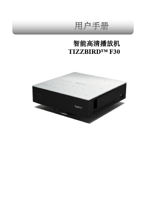
用户手册智能高清播放机TIZZBIRD™ F30目录1.安全须知 (4)2.功能 (5)3.规格 (6)4.部件描述 (7)5.产品配件 (8)6.安装和连接装置 (9)7.使用遥控器操作 (13)8.初始化显示 (14)8.1开机 (15)8.2语言菜单设置 (16)8.3屏幕比例 (17)8.4音频视频设置 (18)8.5网络设置 (20)8.6关机、完全关机 (22)9.启动和待机 (23)9.1主页 (23)9.2封面艺术 (23)9.3电影 (25)9.4待机 (25)10.电影 (26)10.1电影 (26)10.2电影子菜单 (27)10.3添加海报 (28)10.4恢复播放与书签 (30)10.5电影播放菜单 (31)10.6播放速度控制 (31)10.7菜单搜索(时间,章节,书签) (32)10.8菜单信息 (32)10.9菜单字幕 (33)10.10音轨菜单 (33)10.11视频参数菜单 (34)10.12快速播放定位 (34)11.音乐 (35)11.1音乐 (35)11.2排列音乐 (35)11.3音乐播放 (36)11.4音乐播放菜单 (36)12.照片 (37)12.1照片目录 (37)12.2照片目录菜单 (37)12.3照片墙& 照片仓库 (37)12.4照片浏览 (38)12.5幻灯片控制 (38)13.使用文件浏览 (39)13.1文件目录 (39)13.2选择盘 (40)13.3更换字体 (40)14.网络连接 (42)14.1网上冲浪 (42)14.2网页浏览控制 (42)15.安装程序 (43)15.1把程序安装到TizzBird中 (43)15.2玩游戏 (44)16.设置 (45)16.1系统 (45)16.2音频视频 (46)16.3电影 (47)16.4音乐 (48)16.5照片 (49)16.6网络 (50)16.7封面艺术 (50)17.固件升级 (51)17.1本地固件升级 (51)17.1.1设置里的固件升级 (51)17.1.2文件目录下升级 (52)17.2在线升级 (52)1. 安全须知请勿与喇叭等磁性强烈的物品放在一起,避免损伤硬盘中的数据.2.功能TizzBird支持各种高清电影如HDMV和DVD格式如同AVI, MKV, XVID,TS格式,支持流行的H264和VC-1编码。
Uranus AE(Crius)深圳爱康全自动酶免疫使用说明书
32HTU
UT
TU
UT
213H
第三章 装卸、包装和运输 ......................................... 29
3HTUUTTU来自UT214H3.1 介绍................................................................................................................29
20HTU
UT
TU
UT
201H
2.3 系统模块........................................................................................................16
21HTU
UT
TU
UT
20H
2.3.1 一体化机械臂.........................................................................................................16
1HTU
UT
TU
UT
182H
1.2 声明..................................................................................................................7
2HTU
UT
TU
UT
183H
1.3 介绍..................................................................................................................7
索尼sony笔记本只有一个系统分区,怎样划分成多个分区呢?(附解决方法)
索尼sony笔记本默认只有一个系统盘(C盘),很不符合大家的使用习惯,但是很多人都很困惑,不知道应该怎么操作,在保留原系统的情况下怎么样把系统分区划分为多个分区呢?下面我来说一下方法。
索尼SONY笔记本,默认情况下大家只看到有一个分区盘符,其实另外还有两个隐藏的一分,一个只有100M左右(应该是用于安装VAIO CARE拯救大师软件的,是启动分区,启动系统的时候是首先进到这里再从这里引导系统,因为这个原因,要把WIN7删除装XP的话会出错,要装XP就要把这个分区删除或去掉他的启动活动分区),另有一个10左右的分隐藏分区,是用来装一个SONY原始的安装操作系统的,必要是恢复系统用。
昨天一个朋友拿他新买的笔记本来帮他把C盘分成多个分区,经过了一翻折腾,总结了以下可以的方法,同时也把一些不成功的方法分享一下。
原始操作系统为64位的win7家庭普通版目的把287G的C盘,在保留原有系统的情况下,把C盘调整为30G,另建一个50G的D盘,一个100G的E盘,剩下的107G作F盘。
然后把家庭版升级为旗舰版。
由于之前从没接触过SONY的笔记本,走了不少弯路。
首先想到的是用分区魔术师进行分区调整,但用了几个版本的都没有成功,在DOS下,分区魔术师看到的硬盘是错误的,在win7里使用分区魔术师,调整分区后点应用出错,出现错误提示,大概意思是不支持64位操作系统。
(本人英文水平有限,只看到了“失败”,“64位”等一些单词),后来下了一个ADDS(Advanced Data Display System)中文版,在win7里操作成功,但重启后,在进入系统前多了一个英文提示,但进入系统后并没有划分出新区。
网上说中文版不行,英文版可以,本人没经证实是不是英文版的可以,因为我发现了索尼自带软件VAIO Care 拯救大师和win7本身就有这功能。
先来说一下VAIO Care 拯救大师的使用方法,使用VAIO Care 拯救大师只能把C盘分成C盘和D盘两个分区。
Acronis True Image OEM Quick Backup 说明书

用户指南版权所有© Acronis, Inc., 2000-2010。
保留所有权利。
“Acronis” 和“Acronis Secure Zone” 均为Acronis, Inc. 的注册商标。
"Acronis Compute with Confidence"、“Acronis 启动恢复管理器”、“Acronis Active Restore” 及Acronis 标志均为Acronis, Inc. 的商标。
Linux 为Linus Torvalds 的注册商标。
VMware 和VMware Ready 为VMware, Inc. 在美国和/或其他司法管辖地的商标和/或注册商标。
Windows 和MS-DOS 为Microsoft Corporation 的注册商标。
文中引用的所有其它商标和版权均为其各自所有者的财产。
未经版权所有人的明确许可,禁止对本文档进行实质性修改并予以发布。
事先未征得版权所有人的许可,禁止出于商业目的,以任何标准(纸张)书籍形式,发布本作品及其衍生作品。
文档按“原样”提供,对于任何明示或暗示的条件、陈述和保证,包括任何对适销性、对特殊用途的适用性或不侵权的暗示保证,我方概不负责,除非上述免责声明被依法判定为无效。
软件和/或服务在提供时可能包含第三方代码。
上述第三方的许可证条款将在位于安装根目录中的license.txt 文件中详细说明。
您可随时通过以下方式查找最近更新的第三方代码列表以及使用软件和/或服务方面的相关许可证条款:/content/7696目录1简介 (7)1.1 Acronis® True Image OEM Quick Backup 是什么? (7)1.2 Acronis True Image OEM Quick Backup 基本概念 (7)1.3 Acronis True Image OEM Quick Backup 中的新增功能 (9)1.4 系统要求与可支持的媒体 (9)1.4.1最低系统要求 (9)1.4.2可支持的操作系统 (9)1.4.3支持的文件系统 (9)1.4.4支持的存储媒体 (10)2Acronis True Image OEM Quick Backup 安装与启动 (11)2.1 安装Acronis True Image OEM Quick Backup (11)2.2 运行Acronis True Image OEM Quick Backup (11)2.3 激活Acronis True Image OEM Quick Backup (12)2.4 升级Acronis True Image OEM Quick Backup (12)2.5 删除Acronis True Image OEM Quick Backup (13)3一般信息和专有Acronis 技术 (14)3.1 磁盘/分区映像 (14)3.2 完整与增量备份 (14)3.3 备份文件命名约定 (15)3.4 查看磁盘和分区信息 (16)3.5 从系统映像tib 文件启动 (16)4为灾难恢复作好准备 (17)4.1 如何做好准备应对灾难 (17)4.1.1有关测试备份是否可以用于恢复的建议 (17)4.1.2其他建议 (18)4.2 测试可启动应急媒体 (18)4.3 创建自定义应急CD (20)5了解Acronis True Image OEM Quick Backup (21)5.1 程序工作区 (21)5.2 主屏幕 (22)5.3 选项屏幕 (25)6创建备份存档 (27)6.1 准备进行首次备份 (27)6.2 决定要备份的数据 (27)6.3 一些典型的备份方案 (28)6.3.1备份系统分区 (28)6.3.2备份整个系统磁盘 (28)6.3.3备份数据分区或磁盘 (29)6.3.4备份到网络共享 (30)7联机备份 (32)7.1 创建联机备份帐户 (32)7.2 备份到Acronis 联机备份 (32)7.3 从联机存储恢复数据 (35)7.4 管理联机存储 (36)7.5 设置联机备份选项 (37)7.5.1连接尝试 (38)7.5.2存储连接速度 (38)7.5.3存储清理 (39)7.5.4代理服务器设置 (40)7.6 有关为联机存储选择数据的建议 (40)8其他备份功能 (41)8.1 存档至各种不同位置 (41)8.2 备份向导– 详解 (43)8.2.1选择要备份的数据 (43)8.2.2选择存档位置 (44)8.2.3备份方式 (45)8.2.4选择备份选项 (45)8.2.5添加注释 (45)8.2.6备份操作 (45)8.3 调整备份 (46)8.3.1备份选项 (46)8.3.2设置本地存储 (47)9预定任务 (49)9.1 创建预定任务 (49)9.1.1设置为一次性执行 (50)9.1.2设置为事件发生时执行 (50)9.1.3设置定期执行 (51)9.1.4设置为每日执行 (51)9.1.5设置为每周执行 (52)9.1.6设置为每月执行 (52)9.2 管理预定任务 (53)10使用Acronis True Image OEM Quick Backup 进行数据恢复 (55)10.1 恢复系统分区 (55)10.2 将磁盘备份恢复到不同容量的硬盘 (56)10.2.1不使用隐藏分区恢复磁盘 (56)10.2.2恢复带有隐藏分区的磁盘 (58)10.3 恢复数据分区或磁盘 (59)10.4 恢复文件和文件夹 (60)10.4.1从映像存档恢复文件和文件夹 (60)11其他恢复信息 (62)11.1 恢复向导— 详细信息 (62)11.1.1启动恢复向导 (62)11.1.2选择存档 (62)11.1.3恢复方法选择 (63)11.1.4选择要恢复的磁盘/分区 (63)11.1.5选择目标磁盘/分区 (64)11.1.6更改已恢复的分区类型 (65)11.1.7更改已恢复的分区大小和位置 (66)11.1.8为已恢复的分区指定代号 (66)11.1.9设置恢复选项 (66)11.1.10执行恢复 (67)11.2 设置默认恢复选项 (67)11.2.1文件恢复选项 (67)11.2.2覆盖文件选项 (67)11.2.3恢复优先级 (68)12创建可启动媒体 (69)12.1 创建基于Linux 的应急媒体 (69)13浏览存档和加载映像 (72)13.1 加载映像 (72)13.2 卸载映像 (74)14搜索备份存档及其内容 (76)14.1 搜索 (76)14.2 Windows Search 和Google Desktop 集成 (77)14.2.1将Google Desktop 用于Acronis True Image OEM Quick Backup (78)14.2.2将Windows Search 用于Acronis True Image OEM Quick Backup (80)15其他操作 (85)15.1 验证备份存档 (85)15.2 查看任务和日志 (85)15.3 管理备份存档 (86)15.4 删除备份存档 (87)15.5 转移备份存档 (88)16疑难解答 (89)16.1 一般 (89)16.2 安装问题 (89)16.3 备份和验证问题 (90)16.4 恢复问题 (91)16.5 恢复问题后重启性 (92)16.6 其它问题 (92)17硬盘与启动顺序 (94)17.1 设置BIOS 内的启动顺序 (94)17.2 在计算机上安装硬盘驱动器 (94)17.2.1安装IDE 硬盘驱动器(一般方案) (94)17.2.2主板插座、IDE 线缆、电源线 (95)17.2.3配置硬盘驱动器、跳线 (96)17.2.4安装SATA 硬盘 (96)17.2.5新安装内置SATA 盘的步骤 (96)17.3 硬盘抹除方式 (97)17.3.1信息抹除方法的作用原理 (97)17.3.2Acronis 使用的信息抹除方法 (98)18启动参数 (99)18.1 描述 (99)1简介1.1Acronis® True Image OEM Quick Backup 是什么?Acronis True Image OEM Quick Backup 是整合的软件套件,可确保计算机上所有信息的安全。
索尼BIS分析

索尼的BIS分析内容提要:索尼公司自1946年创立以来,在短短的半个多世纪以来从一家不起眼的小企业一跃成为世界知名的跨国公司,成为战后日本经济高速增长和走向国际化的“象征”。
分析索尼的企业行为系统,从索尼的经验中寻找能够给中国企业发展提供借鉴的启示。
关键词:索尼企业行为识别系统索尼公司的前身是1945年成立的东京通讯研究所。
当时二战刚刚结束,研究所在一座破烂不堪的旧木楼里成立,只有职工7人,资金19万日元,基本上是手工制作。
索尼公司自1946年创立以来,在短短的半个多世纪以来从一家不起眼的小企业一跃成为世界知名的跨国公司,目前索尼覆盖民用和专业视听产品、工业电子、通讯产品、信息技术产业及娱乐业等多个领域。
在全球共设有70多家工厂,其中在海外的工厂多大50家,员工总数为17.3万人,年销售额超过了6000亿元,成为日本的代表性企业,称之为“索尼的神话”,成为战后日本经济高速增长和走向国际化的“象征”。
全球化竞争已经成为每个中国公司不能逃避的问题,对索尼企业行为识别系统予以分析,对中国企业的发展有一定的借鉴意义。
一、BIS的认知BIS是企业行为识别系统的简称,是指在理念识别系统上所形成的,用以规范企业内部行为,并达到对外行为统一化(活动统一化)的一系列行为规范和准则。
企业是促进社会发展的重要推动力,而企业具体营运活动既维持企业日常发展经营,又塑造了企业的动态形象。
企业行为识别系统分为对内和对外两个系统,内部系统包括干部与员工教育、工作环境、内部准则;对外则包括市场调查与规划、公共关系、营销等活动。
行为识别的作用在于它是企业理念的升华,视觉识别的再现与强化,它还能使企业形象增值,企业得以扩展,创造出具体、生动、动态的企业形象。
理念就像是人的内在修养,尽管它能在直观上让人感觉出来,但最终还需要通过行为表现出来,而且行为的过程与实现还能不断丰富人的内在涵养。
二、索尼的内部行为系统分析企业内部行为识别是通过对员工的教育、关心,使员工对MI达成共识,从而增强企业的凝聚力和向心力。
NEMA TS2

TS 2-2003 v02.06 Page i
CONTENTS
................................................................................................................................................xv Scope ..........................................................................................................................................................xvi History .........................................................................................................................................................xix TS 2-1998 Update.......................................................................................................................................xxi TS 2-2003 Update........................................................................................................................
DS8000B说明书
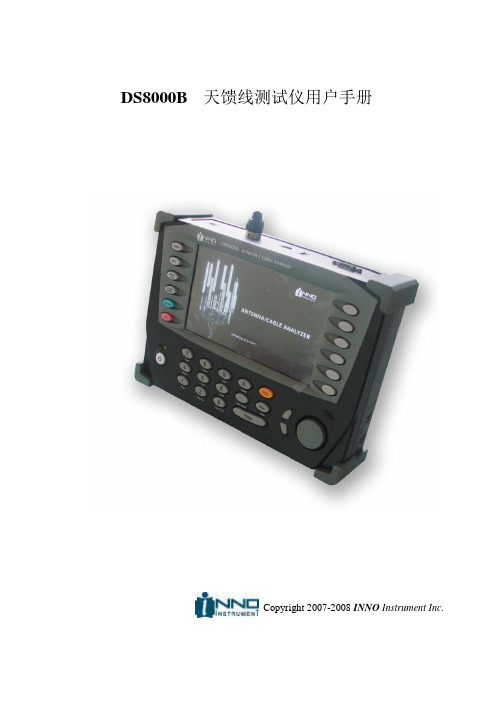
DS8000B天馈线测试仪用户手册Copyright 2007-2008 INNO Instrument Inc.安全指南1.2 安全指南安全记号以下是与安全相关的记号;使用本设备之前,必须要熟悉掌握各种安全记号。
警告 ‘警告’记号代表致命危险;如果没有严格依照手册中的指示内容,可能会给用户造成严 重的损伤。
注意 如果没有严格依照手册中的指示内容,可能会给设备造成严重的损伤。
提示 为了用户的便利,向设备用户提示附加使用信息或者指南。
安全注意事项该产品是安全等级为Ⅰ级的设备,连接电源时,主电源插头必须要连接到设有接地装置的插座上。
必须要使用与本设备配套的电源供给装置。
使用非正规电源供给装置造成设备故障时,制造公司对此不负任何责任。
随意拆卸产品内部或者外部的保护导体,可能会给 DS8000B 天馈线测试仪造成损伤。
故意 拆卸造成设备故障时,属于用户的过失,即使是保修期内,制造公司对此不负任何责任。
输入电源及其他信息设备电源设定在容许电压范围(AC 110 — 250V)内,无须用户手动选择。
本设备没有配备单独的电 源保护用保险丝。
表 1.2.1 输入电源要求事项内置锂离子电池,错误的电源连接可能会导致爆炸。
需要更换电池时,请使用制造公司提 供的标准产品或者可以互换的相关产品;废弃电池时,请严格依照安全指南。
用户手册介绍本手册中详细说明了 DS8000B 产品基本功能和天线或者电缆的检查方法。
DS8000B支持多国语言模式,用户可以任意选用语言模式。
本手册的默认语言模式被设定为 “中文”。
用户手册的构成第一章. 概要对 DS8000B 的主要功能、制造商以及基本配件进行了说明。
第二章. 入门对设备外部界面端口的功能化测试及分析中使用的各种按键进行了说明。
第三章. 驻波比对适用天馈线测试仪功能的天线或者馈线的驻波比测试方法进行了说明;其中包括:系统支持的各种无线通信系统频率登记信息的利用方法和用户设定方法以及标准方法等。
SONY VAIO笔记本热键方案

10-01-08 新增10年最新的VISTA/WIN7方案,09年以后的机子可以试用。
09-12-26 新增W系列和X系列的XP热键方案,因为版本比CW的老,所以改成了0902方案,而CW的方案调整成0903方案。
09-09-24 新增CW系列WINXP热键方案【XP0903】
SmartWi Connection Utility 无线切换管理软件 版本:4.9.4.20091005.2246
【WIN7 0901方案】 09.09.20更新
Sony Shared Library 5.4.0.05200
Setting Utility Series 版本:5.0.0.07300
【WIN7 1002方案】 10.11.27更新
Sony Shared Library 5.7.0.06070 装好重启
Setting Utility Series 版本:5.3.0.07230
VAIO Control Center 控制中心 版本:4.3.0.05310
等安装完热键方案,看下VCC工作正常吗?如果VCC正常,声音调节正常,亮度图标有出来就说明热键已经成功工作了。
如果亮度不能调节,或者亮度只能调一格的情况都是显卡驱动和SONY NC的问题。
先确保SONY NC已经安装驱动,在设备管理器中看下有没有硬件ID:SNY5001的未知设备,如果没有未知设备就不用考虑SONY NC的问题。
VAIO Control Center 控制中心,整合了热键功能 版本:5.0.0.08051
VAIO Power Management 电源管理 版本:5.5.0.05310
meego_百度百科
这一形势迫使今年9月走马上任的CEO Stephen
Elop最终壮士断腕,做出了精简塞班的决定。塞班基金会宣布将于2010年12月17日关闭其网站,结束开放源代码吸引开发者和厂商的徒劳举动。而诺基亚2011年4月将从塞班基金会全面接管对塞班操作系统的控制权。Elop在10月宣布的裁员计划主要涉及的就是塞班智能手机研发部门。尽管诺基亚的管理人员仍旧宣称要在可见的将来生产基于塞班的中低端智能手机,但Elop已经把宝押在和英特尔联合开发的智能机操作系统MeeGo上—后者将用于高端智能任务为我推荐
新闻网页贴吧知道MP3图片视频百科 帮助设置 首页 自然 文化 地理 历史 生活 社会 艺术 人物 经济 科学 体育 核心用户 NBA
该MeeGo用户界面小组还忙于创造手机参考用户经验,并编写了MeeGo用户界面设计原则和互动准则 。
这一里程碑标志着在Moblin和Maemo操作为主要架构和技术的选择决定合并完成已确定。 今天,我们也开放MeeGo基础设施建设 。 MeeGo项目包括:
MeeGo宣传短片,结合Qt和MeeGo触摸UI框架(MTF的) 手机的用户界面和应用子集参考 状态栏:时钟,网络,蓝牙,3G连接,通知,以及电池充电
编辑本段塞班与MeeGo
[1]塞班对于诺基亚的好处是能够为其保持市场占有率:这一从1998年演化来的手机操作系统联盟在非智能手机时代为它赢得了诸多盟友,但它的坏处是没有未来。
在苹果和谷歌专为智能手机设计的操作系统iOS及Android出现后,塞班的地位一直
摇摇欲坠—即使开源也不能解救它。咨询公司Canalys2010年三季度刚出炉的报告称,塞班市场份额为37%。Android市场份额已经达到17%,今年以来,Android的市场份额超越了RIM、苹果和微软的智能手机操作系统—它从零跃居到第二位只用了3年时间。
西门子 HMI 设备OP 73micro,TP 177micro 操作说明
Internet 上的服务与支持
“服务和支持”提供在线服务,使用户能够获得有关 SIMATIC 产品的其它综合信息。其网址是 "/automation/support":
● 新闻快递提供与您的产品有关的最新信息。 ● 使用我们的“服务和支持”搜索引擎可检索一个大型文档库。 ● 一个用来与全球用户及专家交换信息的论坛。 ● 当前的产品信息、FAQ 及下载。 ● 自动化与驱动产品部门的本地代表 ● 在“服务”标题下可以找到现场服务、维修、备件的相关信息以及更多其它信息
我们已对印刷品中所述内容与硬件和软件的一致性作过检查。然而不排除存在偏差的可能性,因此我们不保证印刷 品中所述内容与硬件和软件完全一致。印刷品中的数据都按规定经过检测,必要的修正值包含在下一版本中。
Siemens AG Automation and Drives Postfach 48 48 90437 NÜRNBERG 德国
注意 表示如果不注意相应的提示,可能会出现不希望的结果或状态。
当出现多个危险等级的情况下,每次总是使用最高等级的警告提示。如果在某个警告提示中带有警告可能导致人身 伤害的警告三角,则可能在该警告提示中另外还附带有可能导致财产损失的警告。
合格的专业人员
仅允许安装和驱动与本文件相关的附属设备或系统。设备或系统的调试和运行仅允许由合格的专业人员进行。本文 件安全技术提示中的合格专业人员是指根据安全技术标准具有从事进行设备、系统和电路的运行,接地和标识资格 的人员。
代表处和分公司 如果您对本手册中所描述的产品有任何疑问,请您与当地最近的 SIEMENS 分支机构的代表处 联系。 可在以下网址找到您的联系伙伴:
"/automation/partner"
诺基亚 6670 手机 说明书

出口控制:本手机可能ຫໍສະໝຸດ 含受美国和其他国家或地区的出口法律和法规控制的商品、技术或软件。严禁任何违反法律的转移行为。
1
版权所有 © 2005 诺基亚。保留所有权利。
目录
安全事项............................................ 7
5. 多媒体功能...................................47
照相 / 摄像 ........................................................... 47 拍摄图像 ........................................................ 47 录制视频片段 ................................................ 49
使用拼音输入法 ............................................24 拼音输入法示例:输入 “拼音”................26 笔画输入法 ..........................................................26 使用笔画输入法 ............................................28 笔画输入法示例:输入 “你好”................29 传统英文输入法 ..................................................29 预想英文输入法 ..................................................30 使用预想英文输入法的提示 ........................31 输入空格及换行 ..................................................31 输入符号和标点 ..................................................32 输入数字 ..............................................................32 编辑选项 ..............................................................32 复制文字 ........................................................33
SONY HDR-CX130 CX160 CX180 Handycam 手冊

內建USB電纜
目錄
攝影機不防塵、防滴或防水。請參閱“關於 使用攝影機”(第91頁)。
選單項目、LCD螢幕與鏡頭
Software(1)
“PMB”(軟體,包括“PMB說明”) “Handycam”手冊(PDF)
“操作指南”(1)
在目前的錄製或播放條件下,灰色的選單項 目無法使用。 LCD顯示幕採用超高精密技術製造,可用的 有效畫素超過99.99%。然而,可能有些微小 的黑點和/或亮點(白點、紅點、藍點或綠 點)不斷出現在LCD顯示幕上。這些點是製 造過程的正常結果,並不影響錄製。 盡享實用功能
建議您使用品質優異的Sony附件。 有些國家/地區可能沒有供應Sony優質附 件。
索引
CT
關於本手冊、圖解和螢幕顯示
本手冊中使用的範例影像是以數位相機擷取 作為圖解說明,可能與攝影機實際顯示的影 像和螢幕指示不同。此外,攝影機的圖解和 其螢幕指示也被誇大或簡化以增進理解。 在本手冊中,內建記憶體(HDR-CX160/ CX180)和記憶卡稱為“錄製媒體”。 在本手冊中,以高清晰品質影像(HD)錄製 的DVD光碟均稱為AVCHD錄製光碟。 攝影機與附件的設計和規格若有變更,恕不 另行通知。
選購附件注意事項
儲存所有錄製的影像資料
若要避免影像資料遺失,請定期將所有錄製 的影像儲存到外部媒體。若要將影像儲存在 電腦上,請參閱第44頁,若要將影像儲存在 外接裝置上,則請參閱第50頁。 可用來儲存影像的光碟或媒體類型取決於錄 拍攝模式]。以[60p 製影像時所選的[ ]錄製的動畫可使用外部媒體儲存 質量 ]錄製的動 (第52頁)。以[最高品質 畫可儲存於外部媒體或Blu-ray光碟中(第 48、52頁)。
智能手机硬件组成部分
智能手机硬件组成部分手机系统+CPU+GPU+ROM+RAM+外部存储器+手机屏幕+触摸屏+ 话筒+听筒+摄像头+重力感应+蓝牙+无线连接(wifi)=智能手机基本带3G网络手机系统手机也像电脑一样,有自己的操作系统,没有操作系统的手机就是一块废铁。
目前智能手机的系统主要有symbian、Linux、Palm、BlackBerry、WindowsMobile、Android、iOS(排名不分先后),想要更好的利用智能手机,就必须深入了解它。
智能手机(Smartphone),是指“像个人电脑一样,具有独立的操作系统,可以由用户自行安装软件、游戏等第三方服务商提供的程序,通过此类程序来不断对手机的功能进行扩充,并可以通过移动通讯网络来实现无线网络接入的这样一类手机的总称”。
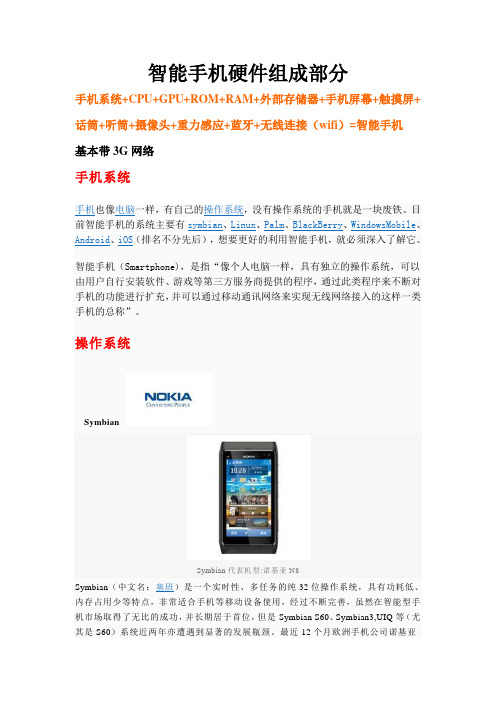
操作系统SymbianSymbian代表机型:诺基亚N8Symbian(中文名:塞班)是一个实时性、多任务的纯32位操作系统,具有功耗低、内存占用少等特点,非常适合手机等移动设备使用,经过不断完善,虽然在智能型手机市场取得了无比的成功,并长期居于首位,但是Symbian S60、Symbian3,UIQ等(尤其是S60)系统近两年亦遭遇到显著的发展瓶颈。
最近12个月欧洲手机公司诺基亚(Nokia)在智能手机市场市占率的滑落是不争的事实。
需要注意的是,并不是所有的Symbian系统都是智能系统,比如S40系统,就不属于智能手机系统。
支持厂商:芬兰诺基亚(日本索尼爱立信、韩国三星已宣布退出塞班阵营)Belle诺基亚600新的塞班Belle系统支持最高6个可横向切换的主屏幕,用户可以在上面随意创建、删除和拖拽Widget插件,和Android非常类似。
动态Widget可将聊天、电子邮件以及社交更新的最新信息实时在桌面展现,非常吸引人。
全新的通知查看系统也是一个亮点——下拉通知菜单中甚至包含了蓝牙、Wi-Fi、移动网络、以及声音模式的快速开关,所有通知都将在这里出现,这是Symbian系统的一个重大更新。
DS_da280

MEMS digital output motion sensor low-power high performance 3-axes “DSC-XYZ” accelerometerKey Features•Supply voltage, 1.62V to 3.6V •For 2x2x1.1 mm LGA-12 package •User selectable range, ±2g, ±4g, ±8g, ±16g •User selectable data output rate •Digital I 2C/SPI output interface •14 bit resolution •Low power consumption •2 Programmable interrupt generators with independent function for motion detection •Free-fall detection •Embedded self-test function •Factory programmable offset and sensitivity • RoHS compliantApplications•User interface for mobile phone and PMP •Display orientation •Gesture recognition •Active/inactive monitoring •Free-fall detection •Double/ Click recognition •Power management •Vibration monitoring •Inclination and tilt sensing •PedometerProduct OverviewThe da280 sensor is a low power high performance capacitive three-axis linear accelerometer developed by micro-machined technology. The device is available in a 2x2x1.1mm land grid array (LGA) and it is guaranteed to operate over an extended temperature range from -40°C to +85°C. The sensor element is fabricated by single crystal silicon with DRIE process and is protected by hermetically sealed silicon cap from the environment. The device features user selectable full scale of ±2g/ ±4g/ ±8g/ ±16g measurement range with data output rate from 1Hz to 1 kHz with signal condition, temperature compensation, self-test, motion detection imbedded. The da280 has a self-test mode for user to check the functioning of the sensor and a power-down mode that makes it good for handset power management. Two independent and flexible interrupts provided greatly simplify the algorithm for various motion status detections. Standard I2C and SPI interfaces are used to communicate with the chip.Content1 Block diagram and pin description (9)1.1 Block diagram (9)1.2 Pin description (9)2 Mechanical and electrical specifications (11)2.1 Mechanical characteristics (11)2.2 Electrical characteristics (12)2.3 Absolute maximum ratings (13)3 Communication interface (14)3.1 Communication interface Electrical specification (14)3.1.1 SPI Electrical specification (14)3.1.2 I2C Electrical specification (15)3.2 Digital interface operation (16)3.2.1 SPI Operation (16)3.2.2 I2C Operation (18)4 Terminology and functionality (20)4.1 Terminology (20)4.1.1 Sensitivity (20)4.1.2 Zero-g level (20)4.2 Functionality (21)4.2.1 Power mode (21)4.2.2 Sensor data (21)4.2.3 Self-test (21)4.2.4 Factory calibration (22)4.3 Interrupt controller (22)4.3.1 General features (22)4.3.2 Mapping (23)4.3.3 Electrical behavior (INT1/INT2 to open-drive or push-pull) (24)4.3.4 New data interrupt (24)4.3.5 Active detection (24)4.3.6 Tap detection (24)4.3.7 Orientation recognition (26)4.3.8 Freefall interrupt (27)5 Application hints (29)6 Register mapping (30)7 Registers description (32)7.1 SOFT_RESET (00H) (32)7.2 CHIPID (01h) (32)7.3 ACC_X_LSB (02H), ACC_X_MSB (03H) (32)7.4 ACC_Y_LSB (04H), ACC_Y_MSB (05H) (32)7.5 ACC_Z_LSB (06H), ACC_Z_MSB (07H) (33)7.6 MOTION_FLAG (09H) (33)7.7 NEWDATA_FLAG (0AH) (34)7.8 TAP_ACTIVE_STATUS (0BH) (34)7.9 ORIENT_STATUS (0CH) (35)7.10 RESOLUTION_RANGE (0FH) (35)7.11 ODR_AXIS (10H) (35)7.12 MODE_BW (11H) (36)7.13 SWAP_POLARITY (12H) (37)7.14 INT_SET1 (16H) (37)7.15 INT_SET2 (17H) (38)7.16 INT_MAP1 (19H) (38)7.17 INT_MAP2 (1AH) (38)7.18 INT_MAP3 (1BH) (39)7.19 INT_CONFIG (20H) (39)7.20 INT_LTACH (21H) (40)7.21 FREEFALL_DUR (22H) (40)7.22 FREEFALL_THS (23H) (41)7.23 FREEFALL_HYST (24H) (41)7.24 ACTIVE_DUR (27H) (41)7.25 ACTIVE_THS (28H) (42)7.26 TAP_DUR (2AH) (42)7.27 TAP_THS (2BH) (42)7.28 ORIENT_HYST (2CH) (43)7.29 Z_BLOCK (2DH) (43)7.30 SELF_TEST (32H) (44)7.31 CUSTOM_OFF_X (38H) (44)7.32 CUSTOM_OFF_Y (39H) (44)7.33 CUSTOM_OFF_Z (39H) (45)7.34 CUSTOM_FLAG (4EH) (45)7.35 CUSTOM_CODE (4FH) (45)7.36 Z_ROT_HODE_TM (51H) (45)7.37 Z_ROT_DUR (52H) (46)7.38 ROT_TH_H (53H) (46)7.39 ROT_TH_L (54H) (46)8 Package information (47)8.1 Outline dimensions (47)8.2 Tape and reel specification (47)9 Revision history (49)List of tablesTable 1.Pin description (10)Table 2.Mechanical characteristic (11)Table 3.Electrical characteristics (12)Table 4.Absolute maximum ratings (13)Table 5.Electrical specification of the SPI interface pins (14)Table 6.Electrical specification of the I2C interface pins (15)Table 7.Mapping of the interface pins (16)Table 8.W1 and W0 settings (17)Table 9.I2C Address (18)Table 10.SAD+Read/Write patterns (18)Table 11.Transfer when master is writing one byte to slave (18)Table 12.Transfer when master is writing multiple bytes to slave (18)Table 13.Transfer when master is receiving (reading) one byte of data from slave (19)Table 14.Transfer when master is receiving (reading) multiple bytes of data from slave (19)Table 15.Self-test difference values (22)Table 16.Interrupt mode selection (22)Table 17.meaning of ‘orient’ bits in symmetric mode (26)Table 18.meaning of ‘orient’ bits in high-asymmetric mode (26)Table 19.meaning of ‘orient’ bits in low-asymmetric mode (27)Table 20.blocking conditions for orientation recognition (27)Table 21.Register address map (30)Table 22. SOFT_RESET register (32)Table 23. I2C Configuration description (32)Table 24. CHIPID register (32)Table 25.ACC_X_LSB register (32)Table 26.ACC_X_MSB register (32)Table 27.ACC_Y_LSB register (33)Table 28.ACC_Y_MSB register (33)Table 29.ACC_Z_LSB register (33)Table 30.ACC_Z_MSB register (33)Table 31.MOTION_FLAG register (33)Table 32.MOTION_FLAG register description (33)Table 33.NEWDATA_FLAG register (34)Table 34.NEWDATA_FLAG register description (34)Table 35.TAP_ACTIVE_STATUS register (34)Table 36.TAP_ACTIVE_STATUS register description (34)Table 37.ORIENT_STATUS register (35)Table 38.ORIENT_STATUS register description (35)Table 39.RESOLUTION_RANGE register (35)Table 40.RESOLUTION_RANGE register description (35)Table 41.ODR_AXIS register (35)Table 42.ODR_AXIS register description (36)Table 44.MODE_BW register description (36)Table 45.SWAP_POLARITY register (37)Table 46.SWAP_POLARITY register description (37)Table 47.INT_SET1 register (37)Table 48.INT_SET1 register description (37)Table 49.INT_SET2 register (38)Table 50.INT_SET2 register description (38)Table 51.INT_MAP1 register (38)Table 52.INT_MAP1 register description (38)Table 53.INT_MAP2 register (38)Table 54.INT_MAP2 register description (39)Table 55.INT_MAP3 register (39)Table 56.INT_MAP3 register description (39)Table 57.INT_CONFIG register (39)Table 58.INT_CONFIG register description (39)Table 59.INT_LTACH register (40)Table 60.INT_LTACH register description (40)Table 61.FREEFALL_DUR register (40)Table 62.FREEFALL_DUR register description (40)Table 63.FREEFALL_THS register (41)Table 64.FREEFALL_THS register description (41)Table 65.FREEFALL_HYST register (41)Table 66.FREEFALL_HYST register description (41)Table 67.ACTIVE_DUR register (41)Table 68.ACTIVE_DUR register description (41)Table 69.ACTIVE_THS register (42)Table 70.ACTIVE_THS register description (42)Table 71.TAP_DUR register (42)Table 72.TAP_DUR register description (42)Table 73.TAP_THS register (42)Table 74.TAP_THS register description (43)Table 75.ORIENT_HYST register (43)Table 76.ORIENT_HYST register description (43)Table 77.Z_BLOCK register (43)Table 78.Z_BLOCK register description (43)Table 79.SELF_TEST register (44)Table 80.SELF_TEST register description (44)Table 81.CUSTOM_OFF_X register (44)Table 82.CUSTOM_OFF_X register description (44)Table 83.CUSTOM_OFF_Y register (44)Table 84.CUSTOM_OFF_Y register description (44)Table 85.CUSTOM_OFF_Z register (45)Table 86.CUSTOM_OFF_Z register description (45)Table 88.CUSTOM_FLAG register description (45)Table 89.CUSTOM_CODE register (45)Table 90.CUSTOM_CODE register description (45)Table 91.Z_ROT_HODE_TM register (45)Table 92.Z_ROT_HODE_TM register description (46)Table 93.Z_ROT_DUR register (46)Table 94.Z_ROT_DUR register description (46)Table 95.ROT_TH_H register (46)Table 96.ROT_TH_H register description (46)Table 97.ROT_TH_L register (46)Table 98.ROT_TH_L register description (46)Table 99.Document revision history (49)List of figuresFigure 1 Block Diagram (9)Figure 2 Pin description (9)Figure 3 SPI slave timing diagram (14)Figure 4 I2C Slave timing diagram (15)Figure 5 Instruction Phase Bit Field (16)Figure 6 MSB First and LSB First Instruction and Data Phases (17)Figure 7 I2C Protocol (18)Figure 8 power mode (21)Figure 9 Interrupt mode (23)Figure 10 Timing of tap detection (25)Figure 11 Definition of vector components (26)Figure 12 da280 I2C electrical connection (29)Figure 13 12 Pin LGA Mechanical data and package dimensions (47)Figure 14 Tape and reel dimension in mm (48)1 Block diagram and pin description1.1 Block diagramCSB SDIOSCLKSDOPS INT1INT2GNDIOFigure 1 Block Diagram1.2 Pin descriptionFigure 2 Pin description2Mechanical and electrical specifications2.1Mechanical characteristicsVdd = 2.5 V, T = 25 °C unless otherwise noted (a)a. The product is factory calibrated at 2.5 V. The operational power supply range is from 1.62V to 3.6 V.Table 2.Mechanical characteristicSymbol Parameter Test conditions Min Type Max UnitFS Measurement range FS bit set to 00±2 g FS bit set to 01 ±4 g FS bit set to 10 ±8 g FS bit set to 11 ±16 gSo Sensitivity FS bit set to 00 4096 LSB/g FS bit set to 01 2048 LSB/g FS bit set to 10 1024 LSB/g FS bit set to 11 512 LSB/gTCSo Sensitivity change vs.temperatureFS bit set to 00 0.01 %/°CTyoff Typical zero-g level offsetaccuracy70 mgTcoff Zero-g level change vs.temperatureMax delta from 25°C ±0.6 mg/°CAn Acceleration noise density FS bit set to 00,Normal Mode,ODR = 1000Hz150 200 ug/sqrt(Hz)Vst Self-test output change X: FS bit set to 00 400 mg Y: FS bit set to 00 400 mg Z: FS bit set to 00 400 mgTop Operation temperature range -40 85 °C2.2Electrical characteristicsVdd = 2.5 V, T = 25 °C unless otherwise notedTable 3.Electrical characteristicsSymbol Parameter Test conditions Min Typ. Max Unit Vdd Supply voltage 1.62 2.5 3.6 V Vdd_IO I/O Pins supply voltage 1.62 3.6 VIdd current consumption innormal modeTop=25℃,ODR=1kHz220 uAIdd_lp current consumption in lowpower modeTop=25℃,ODR=62.5Hz,BW=500Hz40 uAIdd_sm current consumption insuspend modeTop=25℃ 1 uAVIH Digital high level inputvoltageSPI&I2C 0.7*Vdd_IO VVIL Digital low level inputvoltageSPI&I2C 0.3*Vdd_IO VVOH high level output voltage 0.9*Vdd_IO V VOL Low level output voltage 0.1*Vdd_IO V BW System bandwidth 1.95 500 Hz ODR Output data rate 1 1000 Hz Wake-uptimetwu From stand-by 1 ms Start-uptimetsu From power off 3 ms PSRR Power Supply Rejection Rate Top=25℃20 mg/V2.3Absolute maximum ratingsStresses above those listed as “absolute maximum ratings” may cause permanent damage to the device. This is a stress rating only and functional operation of the device under these conditions is not implied. Exposure to maximum rating conditions for extended periods may affect device reliability.Table 4.Absolute maximum ratingsParameter Test conditions Min Max Unit Storage Temperature -45 125 ℃Supply Voltage Supply pins -0.3 4.25 VSupply Voltage Logic pins -0.3 Vdd_IO+0.3 VESD Rating HMB,R=1.5k,C=100pF ±2 kV Mechanical Shock Duration<200us 10,000 gNote: Supply voltage on any pin should never exceed 4.25VThis is a mechanical shock sensitive device, improper handling can cause permanent damages to the part.This is an ESD sensitive device, improper handling can cause permanent damages to the part.3Communication interface3.1Communication interface Electrical specification3.1.1SPI Electrical specificationTable 5.Electrical specification of the SPI interface pinsSymbol Parameter Condition Min Max Unit fsclk Clock frequency Max load on SDIO or SDO = 25pF 10 MHz tsclk_l SLCK low pulse 20tsclk_h SLCK high pulse 20Tsdi_setup SDI setup time 20 ns Tsdi_hold SDI hold time 20 nsTsdo_od SDO/SDI output delay Load = 25pF 30 ns Load = 250pF 40 nsTcsb_setup CSB setup time 20 ns Tcsb_hold CSB hold time 40 nsThe figure below shows the definition of the SPI timing given in Table5:Figure 3 SPI slave timing diagram3.1.2I2C Electrical specificationTable 6.Electrical specification of the I2C interface pinsSymbol Parameter Min Max Unitfscl Clock frequency 400 kHztscl_l SCL low pulse 1.3 ustscl_h SCL high pulse 0.6 us Tsda_setup SDA setup time 0.1 us Tsda_hold SDA hold time 0.0 ustsusta Setup Time for a repeated start condition 0.6 usthdsta Hold time for a start condition 0.6 ustsusto Setup Time for a stop condition 0.6 ustbuf Time before a new transmission can start 1.3 us The figure below shows the definition of the I2C timing given in Table 6:Figure 4 I2C Slave timing diagram3.2Digital interface operationThe da280 supports two serial digital interface protocols for communications as slave with a host device: SPI and I2C. The active interface is selected by the state of the pin PS, 0 selects SPI and 1 selects I2C. By default, SPI operates in 3-wire mode and it can be re-configured by writing 1 to bit ‘SDO_active’ to work in 4-wire mode. Both interfaces share the same pins. The mapping for each interface is given in the following table:Table 7.Mapping of the interface pinsPIN name I2C SPISCL/SCLK Serial clock Serial clockSDA/SDI Serial Data Data input (4-wire mode).Data input/output (3-wire mode)SDO Used to set LSB of I2C address Data output (4-wire mode)CSB Unused Chip select3.2.1SPI OperationThe falling edge of CSB, in conjunction with the rising edge of SCLK, determines the start of framing. Once the beginning of the frame has been determined, timing is straightforward. The first phase of the transfer is the instruction phase, which consists of 16 bits followed by data that can be of variable lengths in multiples of 8 bits. If the device is configured with CSB tied low, framing begins with the first rising edge of SCLK.The instruction phase is the first 16 bits transmitted. As shown in Figure5, the instruction phase is divided into a number of bit fields.Figure 5 Instruction Phase Bit FieldThe first bit in the stream is the read/write indicator bit (R/W). When this bit is high, a read is being requested, otherwise indicates it is a write operation.W1 and W0 represent the number of data bytes to transfer for either read or write (Table8). If the number of bytes to transfer is three or less (00, 01, or 10), CSB can stall high on byte boundaries. Stalling on a non-byte boundary terminates the communications cycle. If these bits are 11, data can be transferred until CSB transitions high. CSB is not allowed to stall during the streaming process.The remaining 13 bits represent the starting address of the data sent. If more than one word is being sent, sequential addressing is used, starting with the one specified, and it either increments (LSB first) or decrements (MSB first) basedon the mode setting.Table 8.W1 and W0 settingsW1:W0 Action CSB stalling00 1 byte of data can be transferred. Optional01 2 bytes of data can be transferred. Optional10 3 bytes of data can be transferred. OptionalNo11 4 or more bytes of data can be transferred. CSB must be heldlow for entire sequence; otherwise, the cycle is terminated.Data follows the instruction phase. The amount of data sent is determined by the word length (Bit W0 and Bit W1). This can be one or more bytes of data. All data is composed of 8-bit words.Data can be sent in either MSB-first mode or LSB-first mode (by setting ‘LSB_first’ bit). On power up, MSB-first mode is the default. This can be changed by programming the configuration register. In MSB-first mode, the serial exchange starts with the highest-order bit and ends with the LSB. In LSB-first mode, the order is reversed. (Figure6)Figure 6 MSB First and LSB First Instruction and Data PhasesRegister bit ‘SDO_active’ is responsible for activating SDO on devices. If this bit is cleared, then SDO is inactive and read data is routed to the SDIO pin. If this bit is set, read data is placed on the SDO pin. The default for this bit is low, making SDO inactive.3.2.2I2C OperationI2C bus uses SCL and SDA as signal lines. Both lines are connected to VDDIO externally via pull-up resistors so that they are pulled high when the bus is free. The I2C device address of da280 is shown below. The LSB bit of the 7bits device address is configured via SA0pin.Table 9.I2C AddressSAD6 SAD5 SAD4 SAD3 SAD2 SAD1 SAD0 W/R0 1 0 0 1 1 SAO 0/1Table 10.SAD+Read/Write patternsCommand SAD[6:1] SAD[0]=SA0 R/W SAD+R/W Read 010011 0 1 01001101(4dh)Write 010011 0 0 01001100(4ch)Read 010011 1 1 01001111(4fh)Write 010011 1 0 01001110(4eh)The I2C interface protocol has special bus signal conditions. Start (S), stop (P) and binary data conditions are shown below. At start condition, SCL is high and SDA has a falling edge. Then the slave address is sent. After the 7 address bits, the direction control bit R/W selects the read or write operation. When a slave device recognizes that it is being addressed, it should acknowledge by pulling SDA low in the ninth SCL (ACK) cycle.At stop condition, SCL is also high, but SDA has a rising edge. Data must be held stable at SDA when SCL is high. Data can change value at SDA only when SCL is low.Figure 7 I2C Protocol4Terminology and functionality4.1Terminology4.1.1SensitivitySensitivity describes the gain of the sensor and can be determined e.g. by applying 1 g acceleration to it. As the sensor can measure DC accelerations this can be done easily by pointing the axis of interest towards the center of the earth, noting the output value, rotating the sensor by 180 degrees (pointing to the sky) and noting the output value again. By doing so, ±1 g acceleration is applied to the sensor. Subtract the larger output value from the smaller one, and dividing the result by 2, leads to the actual sensitivity of the sensor. This value changes very little over temperature and also time. The sensitivity tolerance describes the range of sensitivities of a large population of sensors.4.1.2Zero-g levelZero-g level offset (TyOff) describes the deviation of an actual output signal from the ideal output signal if no acceleration is present. A sensor in a steady state on a horizontal surface measure 0 g in X axis and 0 g in Y axis whereas the Z axis measure 1 g. The output is ideally in the middle of the dynamic range of the sensor (content of output data registers are 00h, data expressed as 2’s complement number). A deviation from ideal value in this case is called Zero-g offset. Offset is to some extent a result of stress to MEMS sensor and therefore the offset can slightly change after mounting the sensor onto a printed circuit board or exposing it to extensive mechanical stress. Offset changes little over temperature; see “Zero-g level change vs. temperature”. The Zero-g level tolerance (TyOff) describes the standard deviation of the range of Zero-g levels of a population of sensors.4.2Functionality4.2.1Power modeThe da280 has three different power modes. Besides normal mode, which represents the fully operational state of the device, there are two special energy saving modes: low-power mode and suspend mode.Figure 8 power modeIn normal mode, all parts of the electronic circuit are held powered-up and data acquisition is performed continuously. In suspend mode, the whole analog part, including the oscillator, Ana LDO, Dig LDO and Drive Buffer are all powered down, no data acquisition is performed and the only supported operation is to read/write the registers. Suspend mode is entered by writing ‘11’ or ‘10’ to the (0x11) ‘pwr_mode’ bits.In low power mode, the device is periodically switching between a sleep phase and a wake-up phase. The wake-up phase essentially corresponding to operation in normal mode with complete power-up of the circuitry. During the sleep phase the analog part except the oscillator is powered down.During the wake-up phase, if a enabled interrupt is detected, the device stays in the wake-up phase as long as the interrupt condition endures (non-latched interrupt), or until the latch time expires (temporary interrupt), or until the interrupt is reset (latched interrupt). If no interrupt detected, the device enters the sleep phase.4.2.2Sensor dataThe width of acceleration data is 14bits given in two’s complement representation. The 14bits for each axis are split into an MSB part (one byte containing bits 13 to 6) and an LSB lower part (one byte containing bits 5 to 0)4.2.3Self-testThis feature permits to check the sensor functionality by applying electrostatic forces to the sensor core instead of external accelerations. By actually deflecting the seismic mass, the entire signal path of the sensor can be tested. Activating the self-test results in a static offset of the acceleration data; any external acceleration or gravitational forceapplied to the sensor during active self-test will be observed in the output as a superposition of both acceleration and self-test signal.The self-test is activated individually for each axis by writing 1 to the (0x32) ‘self_test_en’ bit. It is possible to control the direction of the deflection though bit ‘self_test_sign’ for each axis. The excitation occurs in positive (negative) direction if ‘self_test_sign’ = ‘0b’ (‘1b’).In order to ensure a proper interpretation of the self-test signal it is recommended to perform the self-test for both directions and then to calculate the difference of the resulting acceleration values. Table15 show the difference for each axis.Table 15.Self-test difference valuesX-axis signal Y-axis signal Z-axis signalResulting difference value +0.4g +0.4g +0.4g4.2.4Factory calibrationThe IC is factory calibrated for sensitivity (So) and Zero-g level (TyOff). The trimming values are stored inside the chip’s nonvolatile memory. The trimming parameters are loaded to registers while da280 reset (POR or software reset). This allows using the device without further calibration.4.3Interrupt controllerInterrupt engines are integrated in the da280. Each interrupt can be independently enabled and configured. If the condition of an enabled interrupt is fulfilled, the corresponding status bit is set to 1 and the selected interrupt pin is activated. There are two interrupt pins, INT1 and INT2; interrupts can be freely mapped to any of these two pins. The pin state is a logic ‘or’ combination of all mapped interrupts.4.3.1General featuresAn interrupt is cleared depending on the selected interrupt mode, which is common to all interrupts. There are three different interrupt modes: non-latched, latched and temporary. The mode is selected by the ‘latch_int’ bits according to table16.Table 16.Interrupt mode selectionlatch_int Interrupt mode0000 non-latched0001 temporary latched 250ms0010 temporary latched 500ms0011 temporary latched 1s0100 temporary latched 2s0101 temporary latched 4s0110 temporary latched 8s0111 latched1000 non-latched1001 temporary latched 1ms1010 temporary latched 1ms1011 temporary latched 2ms1100 temporary latched 25ms1101 temporary latched 50ms1110 temporary latched 100ms1111 latchedAn interrupt is generated if its activation condition is met. It can’t be cleared as long as the activation condition is fulfilled. In the non-latched mode the interrupt status bit and the selected pin (INT1 or INT2) are cleared as soon as the activation condition is no more valid. Exceptions to this behavior are the new data and orientation, which are automatically reset after a fixed time.In the latched mode an asserted interrupt status and the selected pin are cleared by writing 1 to (0x21) ‘reset_int’ bit. If the activation condition still holds when it is cleared, the interrupt status is asserted again with the next change of the acceleration registers.In the temporary mode an asserted interrupt and selected pin are cleared after a defined period of time. The behavior of the different interrupt modes is shown in figure 9.Figure 9 Interrupt mode4.3.2MappingThe mapping of interrupts to the interrupt pins is done by registers ‘INT_MAP_x’ (0x19 0x1a and 0x1b), setting int1_inttype (e.g. int1_freefall) to 1 can map this type of interrupt to INT1 pin and setting int2_inttyp to 1 can map this type interrupt to INT2 pin.4.3.3Electrical behavior (INT1/INT2 to open-drive or push-pull)Both interrupt pins can be configured to show desired electrical behavior. The active level for each pin is set by register bit int1_lvl (int2_lvl), if int1_lvl (int2_lvl) = 0 (1), then the pin INT1 (INT2) is 0 (1) active.Also the electric type of the interrupt pin can be selected. By setting int1_od (int2_od) = 1 (0), the interrupt pin output type can be set to be open-drive (push-pull).4.3.4New data interruptThis interrupt serves for synchronous reading of acceleration data. It is generated after an acceleration data was calculated. The interrupt is cleared automatically before the next acceleration data is ready.4.3.5Active detectionActive detection uses the slope between successive acceleration signals to detect changes in motion. An interrupt is generated when the slope (absolute value of acceleration difference) exceeds a preset threshold. The threshold is set with the value of register ‘active_th’ with the LSB corresponding to 16 LSB of acceleration data, that is 3.9mg in 2g-range, 7.8mg in 4g-range, 15.6mg in 8g-range and 31.3mg in 16g-range. And the maximum value is 1g in 2g-range, 2g in 4g-range, 4g in 8g-range and 8g in 16g-range.The time difference between the successive acceleration signals depends is fixed to 1ms.Active detection can be enabled (disabled) for each axis separately by writing ‘1’ to bits ‘active_int_en_x/y/z’. The active interrupt is generated if the slope of any of the enabled axes exceeds the threshold for [‘active_dur’+1] consecutive times. As soon as the slopes of all enabled axes fall below this threshold for [‘active_dur’+1] consecutive times, the interrupt is cleared unless the interrupt signal is latched.The interrupt status is stored in the (0x09) ‘active_int’ bit. The (0x0b) bit ‘active_first_x/y/z’ records which axis triggered the active interrupt first and the sign of this acceleration data that triggered the interrupt is recorded in the (0x0b) bit ‘active_sign’.4.3.6Tap detectionTap detection has a functional similarity with a common laptop touch-pad or clicking keys of a computer mouse. A tap event is detected if a pre-defined pattern of the acceleration slope is fulfilled at least for one axis. Two different tap events are distinguished: A single tap is a single event within a certain time, followed by a certain quiet time. A double tap consist a first such event followed by a second event within a defined time.Single tap interrupt is enabled by writing 1 to the (0x16) ‘s_tap_int_en’ bit and double tap interrupt is enabled by writing 1 to the (0x16) ‘d_tap_int_en’ bit. The status of the single tap interrupt is stored in the (0x09) ‘s_tap_int’ bit and the status of the double tap interrupt is stored in the (0x09) ‘d_tap_int’ bit.The slope threshold for detecting a tap event is set by the (0x2b) “tap_th” bits with the LSB corresponding to 256LSB。
MD随身听最全解读
末代MD传序(参考了墨索里尼传记写法)???在20世纪末至21世纪初的随身音频产品中,有哪一种随身听可以让看过它的人对于它的外观赞不绝口?有哪一种随身听引来了无数的口水,???——???从2006年,它是市场上一枝独秀。
总是有些人认为MD其实是一个失败品,正如一些“标准”的随身听发烧友所说的:“MD音质比不过CD,体积比不过MP3。
”但是,我可以告诉这些人,你们的观点是完全错误的。
不仅仅只是你们以长比短(请问您怎么不拿MD和CD比体积,或者和MP3比音质呢),更因为你们的说法彻底错误!“MD在随身听上的音质足以压倒一切CD随身听(不包括砖块),在体积方面虽然大于闪存MP3,但比硬盘MP3还是要小的多(直到今天也是)!”正文???很早就想写篇关于MD的帖子,但由于本人的惰性,一直拖到了2007年7月,后来由于在论坛发生意外,故直到今天才算是初步完工,在接下JVCMD并给???ST8802002低端SHARP篇???夏普MD无疑是MD中最好的。
无论是理论还是现实,夏普MD的音质都是最好的。
夏普是最早24BIT解码和数字放大技术的应用者。
早在97年夏普就已经是24BIT的解码了,直到1999年的爱华F80仍然还是采用20BIT 解码。
夏普的产品线,我认为要比SONY设计的更科学!ST/DS系列和MT/DR系列的区别绝对不仅仅只是体积和重量上的差别。
在EQ上,夏普分工明确,杜比耳机系统和某些EQ只有单放MD使用,可录MD再高端也只能传统的三段X-BASS(除DR7/77外,它们俱备了高音调节这个EQ)。
而杜比耳机系统又是夏普高端和低端单放MD的一个区别,就像DS5/30/33等无杜比耳机系统,而高端的DS8/70/77等全部配有杜比耳机系统。
当然这也???ST8802接近MD代的夏普MD皆是夸张不规则设计;同时机器正面开始采用高光亮漆。
??今年最引人注目的的还是首款NETMD_IM-MT880,因为NETMD此时被美誉“MP3杀手/终结者”。
国美领航者ERP信息系统
国美领航者ERP信息系统国美电器于2011年12月1日宣布,国美集团领航者ERP Leader信息系统差不多正式实施成功,国美ERP(企业资源打算)信息系统在行业内首次实现利润核算到单店以及全国库存共享。
据了解,这一系统的成功升级将为国美加快推进商业模式变革搭建专门好的后台基础,标志着国美领先进入了商品经营和客户经营的时期。
这一系统是中国零售业最先进的信息化系统。
中国连锁经营协会一位专家表示,当前中国零售行业的信息系统,多是以制造为导向,更多关注的是打算、生产和库存,且信息化系统无法支持零供双方信息的无缝对接。
国美ERP信息系统的成功实施,标志着中国零售业有了与其相匹配的信息化体系。
据介绍,国美新ERP系统首次在中国零售业实现了对单店、单品和个人的治理,同时在这一平台上,供应商能够共享包括市场基础数据、市场竞争信息、服务信息等在内的信息,实现了零供信息的透亮化、及时化、精准化和无缝对接。
据介绍,ERP新系统上线后,国美在全球大型零售行业首次使用批次治理,实现对最小经营单位“门店”和产品全生命周期的治理,甚至细化到对单型号的全程治理。
业内分析人士认为,该系统关于国美供应商而言是较大的利好消息,可关心其操纵库存,操纵资金链风险。
国美电器总裁王俊洲介绍,此次在国美上线的新ERP系统在具体应用方面涉及国美全国1685家门店、433个公司代码、9个物流公司、20万人员,可一次性切换的商品额高达128亿元。
家电业内分析人士认为,该系统重要功能之一是让供货商及时从国美销售终端处获得有效的反馈信息,对操纵库存大有关心,从而使库存居高不下、处于薄利时代的家电供货商稳固资金链。
国美ERP Leader领航者工程由世界排名第一的ERP 软件供应商SAP和全球最具零售治理和IT服务实施体会的惠普公司联合打造,双方依据国美现在及以后的战略规划为其量身定制了SAP ERP版本的信息化建设平台。
该系统的研究始于2007年,彼时国美就开始了对信息化的全球选型,2009年与SAP合作,次年与惠普达成合作,另外还签约了14家国内外知名IT 合作商。
高效率的危害

高效率的危害速度带走了我们的感觉、理智和经验,我们因此而异常脆弱。
如果索尼公司的工作效率太高,世界也许就失去了“随身听”。
随身听必须经过一段时间,才能为市场所接受;如果索尼太讲效率,就会根据顾客最早对随身听的糟糕反馈,放弃这项业务。
可是实际上,许多企业并不像索尼那样幸运,它们因为一味追求效率,不得不面对企业肌体的脆弱,甚至岌岌可危的局面。
走过巴拿马的甘伯亚雨林区,你就会发现许多条由上百万只蚂蚁组成的微型“高速公路”。
每只蚂蚁抬着一小片树叶朝着同一个方向前进,迎面而来的是相同数量的另一队蚂蚁,它们刚将货物运送到老巢,正赶回去拿另一片树叶。
关心环保的游客都异常地小心翼翼,生怕踩到蚂蚁。
这些蚂蚁怎么处理树叶(它们用树叶制成堆肥)并不是本文的主题。
关键是它们组成的这条足球场那么长的高速公路。
目前,许多学者正在研究蚂蚁(和蜜蜂)的群移与组织管理及个人行为之间可能存在的相关性。
关于这些昆虫为何如此擅长艰苦的工作有许多理论。
正如雨林的导游所说,关键原因之一就是冗余。
效率伤害了冗余大自然是神奇的。
不论是在森林还是人脑内部,冗余无处不在。
一项针对中风病人的脑研究显示,女性受到损伤(言语障碍或瘫痪)后恢复速度比男性快,因为女性的大脑各区域连接更加紧密,从而产生足够的冗余,使另一个区域能够加入推动受损部分的修复。
在电影《斯巴达克斯》中有这样惊人的一幕:在一艘大船上,角斗士们被铁链拴在桨上,他们不得不按照鼓声节奏快速或放慢划行,一切都要看船上主人们的意愿。
几十个人不断重复单调的划桨动作。
一旦有人生病,他就会被遗弃,被另一个人取代。
在工业革命早期,工厂里的工人也被当作车轮上的齿轮,是冗余的,随时可以被取代。
在如今这个越来越高效的世界,虽然火箭、芯片、电信、生化各领域都取得了众多突破,许多个人还是被当作大机构中可随时替代的零部件,但这样的人的数量已经大幅度减少,因为机器比人工成本更低。
其后果就是为了效率,我们放弃了冗余的潜在长期优势。
- 1、下载文档前请自行甄别文档内容的完整性,平台不提供额外的编辑、内容补充、找答案等附加服务。
- 2、"仅部分预览"的文档,不可在线预览部分如存在完整性等问题,可反馈申请退款(可完整预览的文档不适用该条件!)。
- 3、如文档侵犯您的权益,请联系客服反馈,我们会尽快为您处理(人工客服工作时间:9:00-18:30)。
索尼说,不就每周一版新系统,他们也可以
就连索尼也要跟上每周一版新系统的节奏了。
索尼最近推出了一个新项目:Android 的概念版(Concept for Android™),这个项目致力于一款基于 Android 5.1 开发的手机系统。
在测试阶段,这个新系统将会保留索尼的应用,并且砍掉部分 Google 系应用,例如视频应用 YouTube。
首批系统将会在Xperia Z3 手机上试用。
为此,一批 500 人的瑞典 Xperia Z3 用户受邀成为实验对象,在 7 月 27 日至 9 月 13日这段时间内,索尼每周就会给这些用户推送一个系统更新版本,让用户使用并且提交反馈。
新系统的重点在于提升用户体验。
索尼发言人告诉科技博客 The Verge:“我们的想法是,我们会对用户的反馈进行评估,并在迭代过程中应用这些经验。
”
“每周发一个新版本”这种规则,其实早已在 Android 的定制系统 CyanogenMod 上实现,而国内的手机厂商比如小米和魅族也已经按照这样的节奏更新系统。
但索尼这样的国际大型手机厂商跟进快节奏的系统版本更新,还是第一次。
这也表示手机业务走下坡的索尼,还在改变他们做手机的方式,尽管这样的小改进,估计也改变不了大局。
除了电视和手机外,索尼跟消费者的联系越来越少了。
2013 年的索尼手机所占的市场份额只有 2.1% ,到 2014 年,索尼手机的市场份额基本没变,而预期亏损却达到了17 亿美元。
首页图来自:站酷海洛创意 题图来自:AndroidHeadlines
好奇心日报 , 每个时代都有最好的媒体。
