英国森威尔自控DDC控制器STEP-3说明书
Estun ER Series Control Cabinet (ERC Controller Ve
ESTUN机器人ER系列控制柜(ERC控制器版本)使用说明书E-0202CN-04感谢您使用埃斯顿机器人产品。
在使用机器人之前,务必仔细阅读机器人安全使用须知,并在理解该内容的基础上使用机器人。
本公司致力于不断提升产品品质,本手册中与产品有关的规格和信息如有改动,恕不另行通知。
本手册中所有陈述、信息和建议均已经过慎重处理,但不保证完全正确。
本公司对于因使用本手册而造成的直接或间接损失不负任何责任。
用户必须对其应用任何产品负全部责任,须谨慎使用本手册及产品。
本手册所有内容的解释权属南京埃斯顿机器人工程有限公司。
本手册未对任何一方授权许可,不得以任何方式复制和拷贝其中的全部或部分内容。
版权所有:南京埃斯顿机器人工程有限公司产品服务热线:400-025-3336地址:南京市江宁经济开发区吉印大道1888号邮编:211102电话:************公司主页:电子邮箱:***************安全使用须知本章说明为安全使用机器人而需要遵守的内容。
在使用机器人之前,务必熟读并理解本章中所述内容。
使用埃斯顿机器人的公司、个人应该熟读所在地区、国家的标准和法律,并且安装适当的安全设施保护机器人的使用人员。
使用前(安装、运转、保养、检修),请务必熟读并全部掌握本说明书和其他附属资料,在熟知全部设备知识、安全知识及注意事项后再开始使用。
但是使用人员即使完全按照手册中给出的所有安全信息进行,埃斯顿公司也无法保证使用人员不会受到任何伤害。
使用人员的定义使用人员的定义如下所示。
•操作人员进行机器人的电源ON/OFF操作。
从操作面板启动机器人程序。
•程序人员进行机器人的操作。
在安全区域内进行机器人的示教等。
•维修人员进行机器人的操作。
在安全区域内进行机器人的示教等。
进行机器人的维护(修理、调整、更换)作业。
操作人员不能在安全区域内进行作业。
程序人员和维修人员可以在安全区域内进行作业。
在进行机器人的操作、编程、维护时,操作人员、程序人员、维修人员必须注意安全,至少应穿戴以下物品进行作业。
HONEYWELL自控教程
H O N E Y W E L L自控教程 Document number:WTWYT-WYWY-BTGTT-YTTYU-2018GT目录目录 (2)1、BAS系统设备检测及调试步骤(STAM)概述 (1)2、DDC 加电检测 (2)Excel 50加电检测步骤 (2)XL50 DDC测试报告 (5)Excel 100 加电检测步骤 (6)XL100 DDC测试报告 (9)Excel 500 加电检测步骤 (10)XL500 DDC-测试报告 (13)3. BA系统监控设备现场调试方案 (14)空调机组的调试方案 (14)空调机组“关”状态下的目视及功能测试 (14)空调机组送风风机启停检查 (14)空调机组温度控制 (15)空调机组过滤器报警 (15)连锁功能测试 (15)机组间连锁功能的测试 (15)最终调整与标定 (15)固定和手动模式的复位 (16)、新风机组测试方案 (16)新风机组“关”状态下的目视及功能测试 (16)新风机组送风风机启停检查 (16)新风机组温度控制 (17)新风机组防冻报警 (17)连锁功能测试 (17)最终调整与标定 (17)固定和手动模式的复位 (18)FCU末端的调试方案 (18)FCU现场调试方案 (18)FCU 调试方案 (18)FCU风机启停检查 (19)固定和手动模式的复位 (19)送、排风机的调试方案 (20)送、排风机“关”状态下的目视及功能测试 (20)送、排风机机启停检查 (20)固定和手动模式的复位 (20)给水系统调试方案 (20)给水水泵“关”状态下的目视及功能测试 (20)水泵启停检查 (21)液位变送器校准 (21)联动功能测试 (21)固定和手动模式的复位 (21)排水系统调试方案 (21)排污泵“关”状态下的目视及功能测试 (21)水泵启停检查 (22)水位开关的测试 (22)联动功能测试 (22)固定和手动模式的复位 (22)照明系统调试方案 (22)照明回路“关”状态下的目视及功能测试 (22)照明回路开关检查 (22)固定和手动模式的复位 (23)冷热站调试方案 (23)直燃机房被控设备目视及功能测试 (23)空调补水系统联动功能测试: (23)1、BAS系统设备检测及调试步骤(STAM)概述本手册所述检测与调试步骤是按照中铁一局BAS系统设计要求进行编制的.编制本手册的目的是:A.在实际调试工作开始之前准确的制定调试计划,并使用户能够了解我们的调试步骤.B.指导调试人员进行系统调试..C.按调试步骤制定及生成准确的调试记录和报告.编制:Date:Approved By:Date:2、DDC 加电检测Excel 50加电检测步骤供电之前:1)对DDC盘内所有电缆和端子排进行目视检查,以修正显性的损坏或不正确安装。
电机控制器和电机控制按钮 Leviton Powerswitch 手册说明书
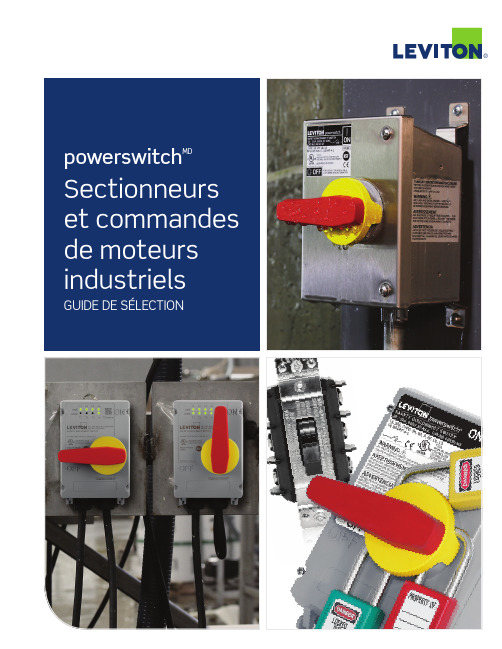
®/powerswitch2Interrupteurs sans boîtier30 A, 40 A et 60 ACommandes de moteurs manuellesSURVOLCes produits Powerswitch MD de qualité industrielle permettent une commande manuelle, sécuritaire et fiable d’une variété de charges motorisées. Pouvant servir de sectionneurs de courant*, ils sont offerts en versions monophasées et triphasées et affichent des valeurs stables à des tensions pouvant atteindre 600 V c.a. et une puissance maximale de 30 ch. Les modèles en boîtiers métalliques et non métalliques de types 1, 3R, 4X, etc. peuvent répondre à un vaste éventail de besoins.* Modèles de 30 et de 40 A seulement.MS603-FWMS303-DSWMS403-DSMS303-DSSpowerswitchMDGUIDE DE COMMANDE/powerswitch 3CARACTÉRISTIQUES• P ièces moulées en thermoplastique résistant aux impacts, aux produits chimiques, aux températures extrêmes, au cheminement et à la formation d’arcs.• M écanisme à cames favorisant les fermetures rapides et les ouvertures lentes des contacts.• H omologation à la norme UL 60947-4-1 (anciennement UL 508).• C ontacts en alliage d’argent, assurant une conductivité et une durabilité maximales.• V ersions de 30 et de 40 A dotées de pinces externes pour le câblage arrière et latéral (les modèles de 60 A permettent les raccordements avant ou arrière, selon le cas).• B arrières entre les bornes qui isolent chaque phase.• B ride, bornes et pinces externes en laiton nickelé pour plus de solidité et une résistance accrue à la corrosion.• L eviers surdimensionnés facilitant la commutation, même par des mains gantées.• V ersions à levier plus court (DSS) pour les modèles de 30 et de 40 A.• G arantie limitée de dix ans.• M odèles de 30 A offerts en versions à levier régulier (DSW) de couleur blanche.‡ Les sectionneurs MS4X sont certifiéspar la NSF.Interrupteurs en boîtier30 A, 40 A et 60 AN1303-TDSMS4X-303N3303-DSN1303-DSGUIDE DE COMMANDE/powerswitch4Sectionneurs en acier inoxydableDessus incliné : 30/32 A et 60 A, sans fusibleDessus plat : 30/32 A, 60 A, 80 A et 100 A, sans fusibleMDS6-AXMDS3-AXMDS8-AXMDS3-ASTSectionneurs de sécuritéSURVOLLes sectionneurs de sécurité Powerswitch MD sont conçus pour offrir un rendement supérieur dans les installations de trans-formation des aliments et boissons, les manufactures, les marinas, les chantiers navals et les usines d’assemblage desintégrateurs de composants (OEM). Offerts dans des boîtiers en PBT ou en acier inoxydable, ces dispositifs sont conçus pour affronter les conditions les plus rigoureuses et répondent aux exigences en matière de sécurité, de résistance aux lavages à grande eau, de réduction des arrêts et de conformité aux codes. Tous les sectionneurs sont également appuyés par une des meilleures garanties de trois ans sur le marché.powerswitchMDIP69KCARACTÉRISTIQUES• A cier inoxydable de type 304 qui résiste à la chaleur, à la corrosion et aux mauvais traitements.• D ispositifs étanches à l’eau et aux particules, submersibles et convenant aux lavages à pressions et à températures élevées.• I P66, IP67, IP68 et IP69K • U L 50E, types 3R, 4X, 12 et 13• V ersions à dessus incliné de 15° vers le mur, faisant glisser l’eau et les débris loin de la porte, de la manette et du joint d’étanchéité à l’avant du dispositif (modèles de 30/32 A et 60 A seulement).• M anette surmoulée qui assure une bonne prise, dure plus longtemps et résiste aux lavages à grande eau.• M anette pouvant être bloquée au moyen de trois cadenas,conformément aux exigences de l’OSHA en matière de verrouillage et d’étiquetage.•C ouvercle amovible qui simplifie et accélère l’installation et l’entretien.• C ertification NSF en ce qui a trait aux exigences en matière d’hygiène des aires de transformation d’aliments et de boissons.• E spacement de près de 2 cm de la surface de fixation qui facilite le nettoyage./powerswitch5GUIDE DE COMMANDELES ACCESSOIRES DES SECTIONNEURS APPARAISSENTSUR LA COUVERTURE ARRIÈREVersions à dessus incliné de 15° vers le mur, faisant glisser l’eau et les débris loin de la porte, de la manette et du joint d’étanchéité à l’avantdu dispositif (modèles de 30/32 A et 60 A seulement)./powerswitch6Sectionneurs non métalliquesModèles avec et sans fusible de 30/32, 60 ou 100 ACARACTÉRISTIQUES• B oîtier en PBT résistant aux impacts, à la corrosion et aux mauvais traitements.• D ispositifs étanches à l’eau et aux particules, submersibles et convenant aux lavages à pressions et à températures élevées.• I P66, IP67, IP68, IP69 et IP69K • U L 50E, types 3R, 4, 4X, 6P , 12 et 13• D essus arrondi faisant tomber l’eau et les débris loin de l’avant du dispositif où se trouvent la porte, la manette et le joint d’étanchéité (modèles de 30/32 A seulement).• M anette surmoulée qui assure une bonne prise, dure plus longtemps et résiste aux lavages à grande eau.• M anette pouvant être bloquée au moyen de trois cadenas,conformément aux exigences de l’OSHA en matière de verrouillage et d’étiquetage.• C ertification NSF en ce qui a trait aux exigences en matière d’hygiène des aires de transformation d’aliments et de boissons.• P lage de températures de fonctionnement de -40 à 75 °C (-40 à 65 °C pour les modèles Inform).• V is en inox captives à fentes triplesAccès en tout temps à des données relativesl’humidité à l’intérieur du boîtier, la continuité vos dispositifs sans avoir à les ouvrir!LDS60-AXLDS30-F AXMODÈLES SANS ÉTIQUETTE!Sectionneurs de sécuritépowerswitchMDTous les sectionneurs de Leviton ont été certifiés aux exigences internationales de la NSF en ce qui a trait à l’hygiène dans la transformation des aliments et boissons de façon àassurer la sécurité et la santé publiques. Les fabricants, les autorités de réglementation et les consommateurs se fient tous à la NSF pour l’élaboration de normes et de programmes de certification qui aident à protéger les aliments, l’eau, les biens de consommation et l’environnement.LDS30-AXCLDS30-CTSIP69KGUIDE DE COMMANDELES ACCESSOIRES DES SECTIONNEURS APPARAISSENT SUR LA COUVERTURE ARRIÈREDessus arrondi faisant tomberl’eau et les débris loin de l’avantdu dispositif où se trouvent la porte, lamanette et le joint d’étanchéité (modèles de30/32 A seulement)./powerswitchAccessoires pour sectionneurs de sécuritéREMARQUE : un support distinct est requis pour fixer les contacts auxiliaires avec fusible. Prière de communiquer avec le service à la clientèle.Dispositifs LEV àinterverrouillage mécanique et technologie Inform Apprenez-en davantage sur /levseries•••••ÉGALEMENT OFFERTS AVEC LA TECHNOLOGIE INFORM!。
森威尔S13 V2.0就地控制器说明书
特点
温度控制适用于2管制,4管制的HVAC系统。温度范围从–40°C到140 °C。
4个独立的PI回路。
8个独立的双回路。
1个模拟输出:可输出DC 0~10V或4~20mA的信号.
1个浮点输出:由2路可控硅输出(24AC)构成。
1个带有传感器的模拟输入:可以接受DC 0~5V, 0~10V或0~20 mA的信号。
控制参数:
HC-03, HБайду номын сангаас-04:加热和制冷比例带设定。工厂设定值是2 K,选0时,比例带控制不起作用。
HC-05:积分部分设定值。大的I积分部分会提高控制回路的响应速度,减少I积分部分会降低响应速度。如果选0值时,积分I部分不起作用。
HC-06: Tn是模拟回路内部积分的复位时间。Tn是积分从0到100%所需要的时间。范围是0.5 – 30分钟。这个参数的设置很大程度上取决于它的应用。对于一个中等大小的房间的温度控制,5-10分钟较为合适。对于VAV box的压力控制来说,3分钟较为合适(取决于执行器的速度)。
控制参数:
HC-08:激活2级加热. HC-09:激活2级制冷压缩机.
HC-10, HC-11:开关下一级加热所必需温度差值。
HC-12:加热或制冷开关延时。目的是避免不必要的加热级开关,因此提高相关设备的使用寿命和节约能源。
加热级延时启动。在同一时间,高一级的加热/制冷不会和低一级加热/制冷同时开启。当低级启动时,高一级在5秒钟内不会开启。
XU输入信号Xp1反比运行比例带
YU通用回路的输出信号Xp2正比运行比例带
wI,wD反比、正比设定点Tn积分复位时间
XDZ死区范围
2
1U-08,1U-09:激活反比或正比控制的2点控制。2点控制可以用于控制单级设备,如压力,液位,湿度等。
DDC操作说明
中央空调自控系统XL50控制器操作说明苏州工业园区汉威控制系统工程有限公司二零一一年五月一.XL50 DDC介绍本控制系统采用Honeywell(霍尼威尔)公司产品Excel 50 DDC(DIRECT DIGITAL CONTROL)直接式多功能数字控制器控制,能根据现场情况方便的增加一“下行键”,移动光标至下一行;“右行键”,移动光标至下一个参数栏;“左行键”,移动光标至上一个参数栏;“增加键”,增加一个修改的单位或切换数字量的一个状态;,减少一个修改的单位或切换数字量的一个状态;三.控制说明新风空调系统的温湿度及压力控制:1.送风温度控制根据送风温度进行空调电动水阀的比例控制。
DDC盘体面板上“工作模式开关打到热源模式”时,即水管内有热水时,DDC自动控制水阀开度;当送风温度高于设定值时,电动水阀开度减小,空调送新风降温;当送风温度低于设定值时,电动水阀开度增大,空调送热风升温。
如果“工作模式开关打到冷源模式”时,即水管内有冷水时,DDC自动控制水阀开度;当送风温度高于设定值时,电动水阀开度增大,空调送冷风降温;当送风温度低于设定值时,电动水阀开度减小,空调送新风升温。
2.送风湿度控制根据送风湿度进行加湿器的开关控制。
当送风湿度低于设定值时,加湿器运行加湿;当送风湿度高于设定值时,加湿器停止工作。
3.送风压力控制根据送风压力进行空调变频风机的比例调节。
当送风压力升高时,变频器输出频率降低;当送风压力减小时,变频器输出频率升高。
从而维持送风压力稳定之目的。
4.风机压差开关联锁保护根据风机压差开关的状态,可以监测空调箱的运行状态。
空调停止工作时,应将空调电动水阀及加湿器强制关闭,起到保护空调箱之目的。
排风机系统进行温湿度及压力控制:1.排风压力控制根据排风压力进行排气变频风机的比例调节。
当排风压力升高时,变频器输出频率降低;当排风压力减小时,变频器输出频率升高。
从而维持排风压力稳定之目的。
2.风机互备控制正常工作时,一台风机运行,一台风机为备用。
DDC控制器介绍【范本模板】
DDC控制器介绍DDC是直接数字(Direct Digital Control)的简称,在DDC系统中计算机通过模拟量输入通道(AI)和开关量输入通道(DI)采集实时数据,然后按照一定的规律进行计算,最后发出控制信号,并通过模拟量输出通道(A0)和开关量输出通道(DO)直接控制生产过程。
DDC控制器控制系统的构成部分1、中央管理计算机。
中央管理计算机设置在中央监控室内,它将来自现场设备的所有信息数据集中提供给监控人员,并接至室内的显示设备、记录设备和报警装置等.2、DDC(直接数字控制器,亦称下位机)。
DDC作为系统与现场设备的接口,它通过分散设置在被控设备的附近收集来自现场设备的信息,并能独立监控有关现场设备.3、通信网络。
中央管理计算机与DDC之间的信息传送,由数据传输线路(通信网络)实现,较小规模的BAS系统可以简单地使用屏蔽双绞线作为传输介质。
4、传感器与执行器。
BAS系统的末端为传感器和执行器,它被装置在被控传感元件和执行元件上。
DDC控制器主要功能DDC主要功能包括以下几个方面:1、对第三层的数据采样设备进行周期性的数据采集。
2、对采集的数据进行调整和处理。
3、对现场采集的数据进行分析,确定现场设备的运行状态。
4、对现场设备运行状况进行检查对比,并对异常状态进行报警处理。
5、根据现场采集的数据执行预定的控制算法而获得控制数据。
6、通过预定控制程序完成各种控制功能,包括比例控制、比例加积分控制、比例加积分加微分控制、开关控制、平均值控制、最大/最小值控制、焓值计算控制、逻辑运算控制和联锁控制.7、向第三层的数据控制和执行设备输出控制和执行命令。
8、通过数据网关或网络控制器连接第一层的设备,与各上级管理计算机进行数据交换,向上传送各项采集数据和设备运行状态信息,同时接收各上级计算机下达的实时控制指令或参数的设定与修改的指令. 模块化设备控制器(MEC)是APOGEE现场管理和控制系统的组成部份,是一个高性能的直接数字控制器(DDC)。
DDC操作说明
中央空调自控系统XL50控制器操作说明苏州工业园区汉威控制系统工程有限公司二零一一年五月一.XL50 DDC介绍本控制系统采用Honeywell(霍尼威尔)公司产品Excel 50 DDC(DIRECT DIGITAL CONTROL)直接式多功能数字控制器控制,能根据现场情况方便的增加一“下行键”,移动光标至下一行;“右行键”,移动光标至下一个参数栏;“左行键”,移动光标至上一个参数栏;“增加键”,增加一个修改的单位或切换数字量的一个状态;,减少一个修改的单位或切换数字量的一个状态;三.控制说明新风空调系统的温湿度及压力控制:1.送风温度控制根据送风温度进行空调电动水阀的比例控制。
DDC盘体面板上“工作模式开关打到热源模式”时,即水管内有热水时,DDC自动控制水阀开度;当送风温度高于设定值时,电动水阀开度减小,空调送新风降温;当送风温度低于设定值时,电动水阀开度增大,空调送热风升温。
如果“工作模式开关打到冷源模式”时,即水管内有冷水时,DDC自动控制水阀开度;当送风温度高于设定值时,电动水阀开度增大,空调送冷风降温;当送风温度低于设定值时,电动水阀开度减小,空调送新风升温。
2.送风湿度控制根据送风湿度进行加湿器的开关控制。
当送风湿度低于设定值时,加湿器运行加湿;当送风湿度高于设定值时,加湿器停止工作。
3.送风压力控制根据送风压力进行空调变频风机的比例调节。
当送风压力升高时,变频器输出频率降低;当送风压力减小时,变频器输出频率升高。
从而维持送风压力稳定之目的。
4.风机压差开关联锁保护根据风机压差开关的状态,可以监测空调箱的运行状态。
空调停止工作时,应将空调电动水阀及加湿器强制关闭,起到保护空调箱之目的。
排风机系统进行温湿度及压力控制:1.排风压力控制根据排风压力进行排气变频风机的比例调节。
当排风压力升高时,变频器输出频率降低;当排风压力减小时,变频器输出频率升高。
从而维持排风压力稳定之目的。
2.风机互备控制正常工作时,一台风机运行,一台风机为备用。
英国森威尔自控DDC控制器STEP-3说明书
六、STEP3 编程说明 ................. 28
七、STEP3 配套软件介绍 ............. 31
八、常见问题诊断 ................... 32
1
英国 森威 尔集 团(香 港)有限公 司 深圳市先派电子有限公司
STEP3 扩展模块
AC24V±20% 50/60Hz 5VA -5…50℃ <95%rh IP20 IP40 建筑及类似应用自动电子调节控制器 EN60730 能量管理设备 UL916 根据 IS9001:2000 最小直径 0.5mm 最大 2×1.5mm2 0.36kg 通道数:4 ,范围:0…150℃, 精度:±0.4℃ 测量电压:最大 DC5.0V,测量电流:2.6…3.4mA 最大连线距离(¢≥0.6mm):最大 300m (3.88Ω线路电阻对应于大约 1℃误差)
质量保证 端子 重量 通用输入 温度传感器 Ni1000/Pt1000/NTC
模拟电压输入 (测量单位℃,%或 无单位)
STEP3
AC24V±20% 50/60Hz 5VA -5…50℃ <95%rh IP20 IP40 建筑及类似应用自动电子调节控制器 EN60730 能量管理设备 UL916 根据 IS9001:2000 最小直径 0.5mm 最大 2×1.5mm2 0.48kg 通道数:4 ,范围:0…150℃, 精度:±0.4 ℃ 测量电压:最大 DC5.0V,测量电流:2.6…3.4mA 最大连线距离(¢≥0.6mm):最大 300m (3.88Ω线路电阻对应于大约 1℃误差) 通道数:4,范围:DC 0…10V,分辨率:0.039V 精度:±0.4℃,最大电流:0.11mA 内阻 R:≥100k 最大连线距离(¢≥0.6mm):最大 300m
Steritest 泵控制器说明书
Avec la fonction Temporisateur l'écran principal.Appuyer surpour ouvrir la têtede pompe.pour sélectionnerle Mode Standard.le Mode Standard.Installer l'unité Steritest™ sur la pompe.Appuyer sur pour fermer la tête de pompe.de la pompe.fixer la valeur du temporisateur .Remarque : Non accessible lorsque la pompe est en fonctionnement.Configurer la pompeMode Régulation de la pressionSans la fonction Temporisateurpour arrêter la pompe avant la fin du temps prédéfini.Utilisation en Mode Stan dardGuide rapide de l'interface utilisateurde la pompe Steritest™ SymbioUtilisation en Mode Méthodes de testà l'écran principal.Remarque : Ce mode n'est accessible que si des méthodes de test ont été préalablement chargées dans la pompeà l'aide du logiciel Steritest™ Symbio.à l'écran précédent..Appuyer surpourouvrir la tête de pompe.à l'étape précédente.à l'écran précédent.Remarque : Pour télécharger le Guide l'utilisateur de la pompe Steritest™ Symbio complet, rendez-vous sur /steritest-symbio.© 2019 Merck KGaA, Darmstadt, Allemagne et/ou ses sociétés affiliées. Tous droits réservés.Merck , Steritest, Sigma-Aldrich et Millipore sont des marques de Merck KGaA, Darmstadt, Allemagne, ou d'une société affiliée. Toutes les autres marques citées appartiennent à leurs propriétaires respectifs. Des informations détaillées sur les marques sont disponibles via des ressources accessibles au public. PF16602FR Version 3.0 01/2019L'activité Life Science de Merck KGaA, Darmstadt, Allemagne opère sous le nom de MilliporeSigma aux États-Unis et au Canada.Appuyer sur pour fermer la tête de pompe.Une fois la dernière étape de la méthode de test terminée, appuyer sur pour ouvrir la tête de pompe.Suivre les instructions de l'étape. Puis appuyer surpour passer à l'étape suivante.。
DDC操作手册 自动控制系统操作手册
自动控制系统操作手冊亚司艾国际贸易有限公司!HoneywellXL20操作說明(一) XL20控制器面板基本按鍵功能1. 跳出本項目與回到上一頁。
2. 進入控制器時間系統。
3. 進入控制器主要設定目錄。
4. 列出警報點。
5. 、、、改變游標位置。
6. 、改變設定值。
7. 確認與輸入。
(二) XL20控制器於送電後必須設定控制器時間,其方法如下:1. 連續按使面板螢幕顯示如下:SCH1mon/Data/Year下頁2. 按鍵使面板螢幕顯示如下:系統時間- - - - - -下頁3. 將游標移動至「系統時間」後按,面板螢幕即顯示如下:- - - - - -日期時間下頁4. 將游標移動至「日期時間」後按,面板螢幕即顯示如下:日期:mon/Day/Year時間:HR/mm下頁5. 將游標移動至日期的月、日、年或時間的小時、分鐘,後按 加以 、 移動游標,即可由 或 改變新的數值,更改結束後按 即可。
(三) XL20控制器主要功能設定:1. 連續按 使面板螢幕退出首頁:2. 按 使面板螢幕顯示如下:3. 若需更動內設之參數,須將游標移至password 處,再連續按兩次,其面板螢幕顯示如下:sch1mon/Day/Year下頁password下頁****password下頁4. 將游標置於 後,按 ,面板螢幕即顯示如下:类比输入:模拟量输入信号。
AHU***室内温度——室内温度传感器感测温度数值AHU***室内湿度——室内温度传感器感测湿度数值类比输出:模拟量输出信号。
AHU***加湿器——该台空调加湿器开度指令AHU***冷水阀——该台空调冰水阀开度指令AHU***热水阀——该台空调热水阀开度指令数位输入:开关量输入信号。
AHU***风机压差——该台空调运行状态AHU***加湿液位——该台空调加湿水盘液位状态下頁 类比输入 类比输出 下頁AHU***滤网检测——该台空调滤网状态AHU***烟感检测——该台空调火警状态数位输出:开关量输出信号。
DDC操作手册
DDC控制系统实验目的1.掌握DDC的操作2.掌握DDC的接线3.熟练的排除DDC的故障设备组成DDC(Direct Digital Control)直接数字控制,通常称为DDC控制器。
DDC系统的组成通常包括中央控制设备(集中控制电脑、彩色监视器、键盘、打印机、不间断电源、通讯接口等)、现场DDC控制器、通讯网络,以及相应的传感器、执行器、调节阀等元器件。
工作原理所有的控制逻辑均由微信号处理器,并以各控制器为基础完成。
这些控制器接收传感器,常用触点或其它仪器传送来的输入信号,并根据软件程序处理这些信号,再输出信号到外部设备。
这些信号可用于启动或关闭机器,打开或关闭阀门或风门,或按程序执行复杂的动作。
这些控制器可用手操作中央机器系统或终端系统。
DDC控制器是整个控制系统的核心,是系统实现控制功能的关键部件。
它的工作过程是控制器通过模拟量输入通道(AI)和数字量输入通道(DI)采集实时数据,并将模拟量信号转变成计算机可接受的数字信号(A/D转换),然后按照一定的控制规律进行运算,最后发出控制信号,并将数字量信号转变成模拟量信号(D/A转换),并通过模拟量输出通道(AO)和数字量输出通道(DO)直接控制设备的运行。
1,本教材使用的品牌为江森自控(图一),有33个输入输出模拟量和数字量,还有1个交流24V电压接口,以及蓝牙接口,网络接口,扩展接口,USB接口等(具体参数见表一)图一数字量输出(DO)模拟量输出(AO)Out1,com1 新风机启Out12,com12 新风机水阀开度控制Out2,com2 1号给水泵Out13,com13 水箱液位模拟值Out3,com3 2号给水泵Out14,com14 光照度模拟值Out4,com4 照明启停数字量输入(DI)模拟量输入(AI)In1,com1 温度Int7,com7 新风机运行状态表一设备操作及电脑控制1,在电脑桌面上找到“图控软件”图标双击打开2,弹出对话框输入用户名和密码(用户名:JFX 密码:Sz-123456)3,进入主机面旋转所有项目—ADS1—新风机设备操作说明手动操作1.打开设备总电开关(QS开关)a)L1,L2,L5,L7 常亮b)总电继电器开始通电i.计算机显示1.风机故障:报警2.风机手自动:关3.风机启停:关4.风机图像:不转2.把手自动开关旋转到手动档位a)L1,L2,L3,L7 常亮b)手动继电器开始通电i.计算机显示1.风机故障:报警2.风机手自动:开3.风机启停:关4.风机图像:不转3.按下手自动开关(SE开关)使其风扇旋转a)L1,L2,L3,L6 常亮b)控制继电器开始通电c)风扇开始旋转i.计算机显示1.风机故障:正常2.风机手自动:开3.风机启停:关4.风机图像:旋转(呈现绿色)自动操作1.打开设备总电开关(QS开关)a)L1,L2,L5,L7 常亮b)总电继电器开始通电i.计算机显示1.风机故障:报警2.风机手自动:关3.风机启停:关4.风机图像:不转2.把手自动开关旋转到自动档位a)L1,L2,L4,L7 常亮b)自动继电器开始通电i.计算机显示1.风机故障:报警2.风机手自动:开3.风机启停:关4.风机图像:不转3.用电脑打开风机启停开关使其风扇旋转a)L1,L2,L4,L6 常亮b)控制继电器开始通电c)风扇开始旋转i.计算机显示1.风机故障:正常2.风机手自动:开3.风机启停:开4.风机图像:旋转(呈现绿色)实验。
采暖温度控制器使用说明书森威尔SA.
S A S 816W H B -0-D F 采暖温度控制器使用说明书森威尔SA S816WH B-0-DF 采暖温度控制器主要用于无线控制壁挂炉水暖系统,用以无线控制电热执行器的开启与关闭,达到舒适控温的目的。
技术指标:工作电压:2节AA 干电池 无线收发频率:868MH Z (FSK ) 无线收发距离:空旷100米 温度精度:±1℃或±1℉温度控制范围:5℃~30℃ (41℉~86℉) 工作环境温度:0℃~+50℃(32F ~122F ) 贮存环境温度:-10℃~+60℃(14F ~140F ) 外形尺寸:86×86×32m m (通用于86接线盒)按键及显示功能说明:安装及无线对码说明:1、 如图1安装示意图所示,把产品的安装螺丝拧下,分开面板和底壳,用PM4*25 HC(+)的螺丝将底壳紧固在86盒上。
2、 正确装入2节AA 的电池,然后将发射器面板与装在86盒上的底壳扣合好,拧紧安装螺丝即完成安装。
图1安装示意图(1) 2位温度显示区 (2) 房间温度标志 (3) 地板温度标志 (4) 舒适运行模式标志 (5) 节能运行模式标志 (6) 电池低电量报警标志 (7) 制热输出标志(8) 制冷输出及通讯错误报警标志 (9) 摄氏温度或华氏温度显示符 (10) LCD 显示区 (11) ON/OFF 开关(12) 温度设定旋转刻度盘 (13) 旋盘下隐藏的对码按键3.接收部分关机模式下长按接收部分按键超过3秒,黄灯亮表示接收处于对码状态,旋转发射部分旋盘直到刻度“1”对准LCD,然后取下旋盘,长按隐藏按键1秒以上则进入对码过程,对码成功发射部分对码码值闪烁显示3秒表示对码成功,否则对码不成功。
(见图2)图2示意图操作说明:1、在开机状态下,旋转旋盘,进入温度设定模式,显示屏闪烁显示对应的设定温度值。
无旋转,5S后自动返回显示实时房间温度。
2、开关功能及运行模式选择:此时开关(11)作为开关机功能,关机时屏幕显示OF,并停止输出。
威尔恩灯光控制器说明书
For warranty information regarding this product, visit /warranty•Proper installation of this product requires the installer to have a good understanding of automotive electronics, systems and procedures.•Whelen Engineering requires the use of waterproof butt splices and/or connectors if that connector could be exposed to moisture.•Any holes, either created or utilized by this product, should be made both air- and watertight using a sealant recommended by your vehicle manufacturer.•Failure to use specified installation parts and/or hardware will void the product warranty.•If mounting this product requires drilling holes, the installer MUST be sure that no vehicle components or other vital parts could be damaged by the drilling process. Check both sides of the mounting surface before drilling begins. Also de-burr the holes and remove any metal shards or remnants. Install grommets into all wire passage holes.•If this manual states that this product may be mounted with suction cups, magnets, tape or Velcro®, clean the mounting surface with a 50/50 mix of isopropyl alcohol and water and dry thoroughly.•Do not install this product or route any wires in the deployment area of your air bag. Equipment mounted or located in the air bag deployment area will damage or reduce the effectiveness of the air bag, or become a projectile that could cause serious personal injury or death. Refer to your vehicle owner’s manual for the air bag deployment area. The User/Installer assumes full responsibility to determine proper mounting location, based on providing ultimate safety to all passengers inside the vehicle.•For this product to operate at optimum efficiency, a good electrical connection to chassis ground must be made. The recommendedprocedure requires the product ground wire to be connected directly to the NEGATIVE (-) battery post (this does not include products that use cigar power cords).•If this product uses a remote device for activation or control, make sure that this device is located in an area that allows both the vehicle and the device to be operated safely in any driving condition.•Do not attempt to activate or control this device in a hazardous driving situation.•This product contains either strobe light(s), halogen light(s), high-intensity LEDs or a combination of these lights. Do not stare directly into these lights. Momentary blindness and/or eye damage could result.•Use only soap and water to clean the outer lens. Use of other chemicals could result in premature lens cracking (crazing) and discoloration. Lenses in this condition have significantly reduced effectiveness and should be replaced immediately. Inspect and operate this product regularly to confirm its proper operation and mounting condition. Do not use a pressure washer to clean this product.•It is recommended that these instructions be stored in a safe place and referred to when performing maintenance and/or reinstallation of this product.•FAILURE TO FOLLOW THESE SAFETY PRECAUTIONS AND INSTRUCTIONS COULD RESULT IN DAMAGE TO THE PRODUCT OR VEHICLE AND/OR SERIOUS INJURY TO YOU AND YOUR PASSENGERS!A u t o m o t i v e : Warnings to InstallersWhelen’s emergency vehicle warning devices must be properly mounted and wired in order to be effective and safe. Read and follow all of Whelen’s written instructions when installing or using this device. Emergency vehicles are often operated under high speed stressful conditions which must be accounted for when installing all emergency warning devices. Controls should be placed within convenient reach of the operator so that they can operate the system without taking their eyes off the roadway. Emergency warning devices can require high electrical voltages and/or currents. Properly protect and use caution around live electrical connections.Grounding or shorting of electrical connections can cause high current arcing, which can cause personal injury and/or vehicle damage, including fire. Many electronic devices used in emergency vehicles can create or be affected by electromagnetic interference. Therefore, after installation of any electronic device it is necessary to test all electronic equipment simultaneously to insure that they operate free of interference from other components within the vehicle. Never power emergency warning equipment from the same circuit or share the same grounding circuit with radio communication equipment. All devices should be mounted in accordance with the manufacturer’s instructions and securely fastened to vehicle elements of sufficient strength to withstand the forces applied to the device. Driver and/or passenger air bags (SRS) will affect the way equipment should be mounted. This device should be mounted by permanent installation and within the zones specified by the vehicle manufacturer, if any. Any device mounted in the deployment area of an air bag will damage or reduce the effectiveness of the air bag and may damage or dislodge the device. Installer must be sure that this device, its mounting hardware and electrical supply wiring does not interfere with the air bag or the SRS wiring or sensors. Mounting the unit inside the vehicle by a method other than permanent installation is not recommended as unit may become dislodged during swerving; sudden braking or collision. Failure to follow instructions can result in personal injury. Whelen assumes no liability for any loss resulting from the use of this warning device. PROPER INSTALLATION COMBINED WITH OPERATOR TRAINING IN THE PROPER USE OF EMERGENCY WARNING DEVICES IS ESSENTIAL TO INSURE THE SAFETY OF EMERGENCY PERSONNEL AND THE PUBLIC.Warnings to UsersWhelen’s emergency vehicle warning devices are intended to alert other operators and pedestrians to the presence and operation of emergency vehicles and personnel. However, the use of this or any other Whelen emergency warning device does not guarantee that you will have the right-of-way or that other drivers and pedestrians will properly heed an emergency warning signal. Never assume you have the right-of-way. It is your responsibility to proceed safely before entering an intersection, driving against traffic, responding at a high rate of speed, or walking on or around traffic lanes. Emergency vehicle warning devices should be tested on a daily basis to ensure that they operate properly. When in actual use, the operator must ensure that both visual and audible warnings are not blocked by vehicle components (i.e.: open trunks or compartment doors), people, vehicles, or other obstructions. It is the user’s responsibility to understand and obey all laws regarding emergency warning devices. The user should be familiar with all applicable laws and regulations prior to the use of any emergency vehicle warning device. Whelen’s audible warning devices are designed to project sound in a forward direction away from the vehicle occupants. However, because sustained periodic exposure to loud sounds can cause hearing loss, all audible warning devices should be installed and operated in accordance with the standards established by the National Fire Protection Association.Safety FirstThis document provides all the necessary information to allow your Whelen product to be properly and safely installed. Before beginning the installation and/or operation of your new product, the installation technician and operator must read this manual completely. Important information is contained herein that could prevent serious injury or damage.WARNING: This product can expose you to chemicals including Methylene Chloride which is known to the State of California to cause cancer, and Bisphenol A, which is known to the State of California to cause birth defects or other reproductive harm. For more information go to .©1997 Whelen Engineering Company Inc.Form No.13240C (072607)Installation Guide:BL8140 Relay Box51 Winthrop RoadChester, Connecticut 06412-0684Phone: (860) 526-9504Internet: Salese-mail:*******************CustomerServicee-mail:*******************®ENGINEERING COMPANY INC.Selecting a mounting location...The logical choice for a mounting area would be a trunk or similar compartment. However, due to the wide variety of vehicles onto which the BL8140 could be installed, this is not always possible. The following guidelines will help the installer select an acceptable alternative:A)The BL8140 should be mounted on a metal surface to aidheat dissipation. Be sure that this surface is not one that either generates or is exposed to excessive heat during normal operation of the vehicle.B)Do not select a location where the BL8140 will be exposedto potential damage from any unsecured or loose equipment in the vehicle.C)Be sure the area selected will not allow the BL8140 to beexposed to water!D)When routing the BL8140’s wires, it is important to choosea path that will keep these wires away from excessive heatand from any vehicle equipment that could compromise the integrity of the wires (ex. trunk lids, door jams, etc.). WARNING!All customer supplied wires, that connect to the positive (+) terminal of the battery,must be sized to supply at least 125% ofthe maximum operating current, andfused “at the battery” to carry the load! Note:When extending the communication wires (BLUE & GREY), similar “twistedpair” wires MUST be used!When the best mounting location has been determined, securely fasten the BL8140 to its mounting surface using the supplied hardware.Caution:As it will be necessary to drill holes into the mounting surface, the installer MUST be surethat no vehicle components or other vitalparts could be damaged by the drillingprocess. Check both sides of the mountingsurface before drilling!BL8140 Dip Switches...All BL8140’s are shipped with a default dip switch configuration. These switches determine several aspects of the BL8140, including how the unit is addressed within the network. This section will offer a brief explanation of dip switch functionality. For a more detailed explanation of these switches, please refer to the “Advanced Settings” section found in the second half of this manual.The default dip switch configuration for the BL8140 is as follows:Dip Switch#Default Position1DOWN2DOWN3DOWN4UP5DOWN6UP7UP8UPSettings for use with MPC01 ver 2.xSettings for use with MPC01 ver 1.xDip Switch 1- This switch’s position should not be changed.Doing so effectively disables the ability of theBL8140 to properly operate.Dip Switch 2&3-These two switches work in conjunction witheach other. Their positions determine howthe output control channels are interpreted bythe network. Please refer to the “AdvancedSettings” section for a full explanation.Dip Switch 4-This switch controls the operation of push-button switch #9 on the Multi-PurposeController. Please refer to the AdvancedSettings section for a more detailedexplanation.Dip Switch 5&6-These two switches work in conjunction witheach other. Their positions determine thenetwork address of the BL8140s outputcontrol channel 1. The default address is 3. Dip Switch 7&8-These two switches work in conjunction witheach other. Their positions determine thenetwork address of the BL8140s outputcontrol channel 2. The default address is 4.Wiring the BL8140...The following diagram will illustrate the necessary wiring connections needed for BL8140 operation.BL8140 Channels...The BL8140 offers a total of 8 outputs located at the front of the unit (see Fig. 1). The outputs are identified in the illustration by numbers 1 through 8, counting from left to right. These outputs are grouped into “channels”. Each channel is recognized by the network as either a BL405 or a BL420A, depending upon the dip switch configuration.Channel 1 is comprised of outputs 1 - 4. Outputs 1-A, 1-B and 1-C are not individually controlled and function as a single, high-current output rated for up to 40 amps. Output’s 2, 3 and 4 are individually controlled and are rated for up to 20 Amps each.Channel 2 is comprised of outputs 5 - 8, each being individually controlled. Output 5 - 8 are rated for up to 10 Amps.When the dip switches are configured for ver 1.x of the configuration software, channel 1 and channel 2 emulate the BL405 halogen flasher. As such, the network believes that there are actually two BL405 flashers installed; channel 1 and channel 2. The following will illustrate how the outputs of the BL8140 are controlled by the Multi-Purpose Controller.Channel 1 (emulating a BL405 at address 1)BL8140 output #acts as BL405 output #1A, 1B & 1C1223344Channel 2 (emulating a BL405 at address 2)BL8140 output #acts asBL405 output #51627384When the BL8140 has been installed, it will be operated as configured by the Multi-Purpose Controller configuration software.Please refer to the configuration software manual for software configuration information.Advanced Settings...This section will provide advanced technicians with dip switch information that will allow the BL8140 to be configured in different ways for different needs. Please note that only experienced serial communications technicians should alter the default dip switch configuration. It is a good idea to record any changes made to the current dip switch configuration.Dip Switch 1-This switch is not used and should remain inthe default (DOWN) position.Dip Switch 2 & 3-These switches determine the emulation modeof the BL8140.DS#2DS#3UP UP In this position, the BL8140 tells the networkthat there are two BL405 4-outlet flashers onthe network. Channel 1 is seen as a BL405 andchannel 2 is seen as a BL405. Refer to the“BL8140 Channels...” section of this guide forinformation on output control and assignment. DOWN UP In this position, the BL8140 tells the networkthat channel 1 is a BL420 and that channel 2 isa BL405.UP DOWN In this position, the BL8140 tells the networkthat channel 1 is a BL405 and that channel 2 isa BL420.DOWN DOWN In this position, the BL8140 tells the networkthat channel 1 is a BL420 and that channel 2 isa BL420. DOWN/DOWN is the defaultposition for these switches.Dip Switch 4-This switch determines if or how the BL8140’s#8 output (channel 2/output 4) is controlled.UP In this position the BL8140 allows output #8 tobe controlled in a manner determined by theconfiguration software. UP is the defaultposition for this switch.DOWN In this position, output 8 control is assigned topush-button switch 9 on the MPC01 controlhead. This momentary switch, when pressed,“latches” output 8 on. Pressing this switch again“latches” output 8 off.Dip Switch 5 & 6-These switches determine the network addressof BL8140 channel 1.DS#5DS#6DOWN DOWN In this position, the address of channel 1 is 1. UP DOWN In this position, the address of channel 1 is 2. DOWN UP In this position, the address of channel 1 is 3.DOWN/UP is the default position for theseswitches.UP UP In this position, the address of channel 1 is 4. Dip Switch 7 & 8-These switches determine the network addressof BL8140 channel 2.DS#7DS#8DOWN DOWN In this position, the address of channel 2 is 1. UP DOWN In this position, the address of channel 2 is 2. DOWN UP In this position, the address of channel 2 is 3. UP UP In this position, the address of channel 2 is 4.UP/UP is the default position for theseswitches.I mportant Addressing Note! Channels 1 and 2 can NEVER share a common address UNLESS the two channels are emulating different products!Note:Although the BL8140 can emulate both the BL405 and the BL420, it does not emulate all oftheir characteristics. Major differences include:•The outputs of a channel emulating a BL405 or a BL420 do not share the same amperage limitations as do theoutputs of the models being emulated. See the wiringdiagram for output limitations.•The BL8140 can not “flash” an output. Regardless of the flash setting within the MPC01 configuration software,the BL8140 outputs are either on or off.。
(完整word)DDC操作手册
DDC控制系统实验目的1.掌握DDC的操作2.掌握DDC的接线3.熟练的排除DDC的故障设备组成DDC(Direct Digital Control)直接数字控制,通常称为DDC控制器.DDC 系统的组成通常包括中央控制设备(集中控制电脑、彩色监视器、键盘、打印机、不间断电源、通讯接口等)、现场DDC控制器、通讯网络,以及相应的传感器、执行器、调节阀等元器件。
工作原理所有的控制逻辑均由微信号处理器,并以各控制器为基础完成。
这些控制器接收传感器,常用触点或其它仪器传送来的输入信号,并根据软件程序处理这些信号,再输出信号到外部设备。
这些信号可用于启动或关闭机器,打开或关闭阀门或风门,或按程序执行复杂的动作。
这些控制器可用手操作中央机器系统或终端系统。
DDC控制器是整个控制系统的核心,是系统实现控制功能的关键部件。
它的工作过程是控制器通过模拟量输入通道(AI)和数字量输入通道(DI)采集实时数据,并将模拟量信号转变成计算机可接受的数字信号(A/D转换),然后按照一定的控制规律进行运算,最后发出控制信号,并将数字量信号转变成模拟量信号(D/A转换),并通过模拟量输出通道(AO)和数字量输出通道(DO)直接控制设备的运行.1,本教材使用的品牌为江森自控(图一),有33个输入输出模拟量和数字量,还有1个交流24V电压接口,以及蓝牙接口,网络接口,扩展接口,USB接口等(具体参数见表一)图一数字量输出(DO)模拟量输出(AO)Int15,com1 52号给水泵故障报警Int16,com162号给水泵手自动Int17,com17照明运行状态Int18,com18照明手自动表一设备操作及电脑控制1,在电脑桌面上找到“图控软件”图标双击打开2,弹出对话框输入用户名和密码(用户名:JFX 密码:Sz—123456)3,进入主机面旋转所有项目-ADS1—新风机设备操作说明手动操作1.打开设备总电开关(QS开关)a)L1,L2,L5,L7 常亮b)总电继电器开始通电i.计算机显示1.风机故障:报警2.风机手自动:关3.风机启停:关4.风机图像:不转2.把手自动开关旋转到手动档位a)L1,L2,L3,L7 常亮b)手动继电器开始通电i.计算机显示1.风机故障:报警2.风机手自动:开3.风机启停:关4.风机图像:不转3.按下手自动开关(SE开关)使其风扇旋转a)L1,L2,L3,L6 常亮b)控制继电器开始通电c)风扇开始旋转i.计算机显示1.风机故障:正常2.风机手自动:开3.风机启停:关4.风机图像:旋转(呈现绿色)自动操作1.打开设备总电开关(QS开关)a)L1,L2,L5,L7 常亮b)总电继电器开始通电i.计算机显示1.风机故障:报警2.风机手自动:关3.风机启停:关4.风机图像:不转2.把手自动开关旋转到自动档位a)L1,L2,L4,L7 常亮b)自动继电器开始通电i.计算机显示1.风机故障:报警2.风机手自动:开3.风机启停:关4.风机图像:不转3.用电脑打开风机启停开关使其风扇旋转a)L1,L2,L4,L6 常亮b)控制继电器开始通电c)风扇开始旋转i.计算机显示1.风机故障:正常2.风机手自动:开3.风机启停:开4.风机图像:旋转(呈现绿色)实验。
DDC操作手册 自动控制系统操作手册
自动控制系统操作手冊亚司艾国际贸易有限公司!HoneywellXL20操作說明(一) XL20控制器面板基本按鍵功能1. 跳出本項目與回到上一頁。
2. 進入控制器時間系統。
3. 進入控制器主要設定目錄。
4. 列出警報點。
5. 、、、改變游標位置。
6. 、改變設定值。
7. 確認與輸入。
(二) XL20控制器於送電後必須設定控制器時間,其方法如下:1. 連續按使面板螢幕顯示如下:SCH1mon/Data/YearHR/mm下頁2. 按鍵使面板螢幕顯示如下:系統時間- - - - - -- - - - - -下頁3. 將游標移動至「系統時間」後按,面板螢幕即顯示如下:- - - - - -日期時間- - - - - -下頁4. 將游標移動至「日期時間」後按,面板螢幕即顯示如下:日期:mon/Day/Year時間:HR/mm下頁5. 將游標移動至日期的月、日、年或時間的小時、分鐘,後按加以、移動游標,即可由或改變新的數值,更改結束後按即可。
(三) XL20控制器主要功能設定:1. 連續按使面板螢幕退出首頁:sch1mon/Day/YearHR/mm/下頁2. 按 使面板螢幕顯示如下:3. 若需更動內設之參數,須將游標移至 password 處,再連續按 兩次,其面板螢幕顯示如下:4. 將游標置於 後,按 ,面板螢幕即顯示如下: 类比输入:模拟量输入信号。
AHU***室内温度——室内温度传感器感测温度数值AHU***室内湿度——室内温度传感器感测湿度数值类比输出:模拟量输出信号。
AHU***加湿器——该台空调加湿器开度指令AHU***冷水阀——该台空调冰水阀开度指令AHU***热水阀——该台空调热水阀开度指令数位输入:开关量输入信号。
password****下頁****password****更改 下頁下頁 类比输入类比输出数位输入下頁AHU***风机压差——该台空调运行状态AHU***加湿液位——该台空调加湿水盘液位状态AHU***滤网检测——该台空调滤网状态AHU***烟感检测——该台空调火警状态数位输出:开关量输出信号。
DDC说明书解析
图1:外观示意图及左视图
说明
指示灯:
维护灯(黄色):正常监控下不亮,下载程序时闪亮。
电源灯(红色):模块上电后常亮。
DO1~DO4:工作状态指示灯(绿色),相应路继电器吸合时亮。
UO1~UO2:工作状态指示灯(绿色),相应路继电器吸合时亮。
按键:
维护:维护键。
复位:复位键。
DO1~DO4,UO1、UO2,AO1、AO2:自动/强制输出转换按键,按键按下时相应路为强制输出。
电位器:
手动调节AO1、AO2,UO1、UO2:调节相应端口的输出电压值。
3.2工作原理:
HW-BA5201DDC控制模块的硬件部分主要由电源整流、电源变换、神经元模块、按键、指示、A/D变换、DO驱动以及D/A变换等8部分组成。电源整流将无极性24V直流电源转换为有极性直流24V电源;电源变换电路将输入24V电压变换为5V输出电压,电压变换芯片采用LM2575;神经元模块为CPU;A/D变换芯片采用TLC1543,具有11通道,10位精度;D/A变换芯片采用TLC5617,具有2通道,10位精度;DO驱动电路采用ULN2803芯片,该芯片片内具有8个大电流达林顿开关,能驱动电流高达500毫安的负载,片内的反向二极管起钳位保护作用。两个按键一个为复位键,一个为SERVICE键。指示灯一个为电源指示,一个为SERVICE指示。
图2:插针X1~X11跳线示意图
X12与X14、X13与X15插针跳线确定了UO1~UO2信号输出模式,通过跳线可将UO设置成DO或AO输出模式。插针X12~X15跳线说明如图3所示:
图3:插针X12~X15跳线示意图
森威尔地暖用温控器SA803说明书
SAS803采暖系列是一款用于控制电加热系统(或水加热系统)中发热材料或控制阀门开与关的可编程控制器。
本产品有两种型号:SAS803FHL-7SAS803WHL-7技术指标电源电压: 100-240VAC 50/60Hz 房间控温范围: 5°C—35°C地板控温范围: 5°C—99°C控温精度: ± 0.5°C外形尺寸: 86*86*18mm温度校正系数:± 6工作环境温度:0℃-+50℃贮存环境温度:-10℃-+60℃最大负载:3A或16A防护等级IP21按键与显说明按键说明(图1):1):电源键:温控器开机或关机键2): 时钟键:在待机或运行模式下短按进入,时钟,星期天调整程序。
通过+ -键调整;在运行模式下且当前运行程序是ALL情况下,长按3秒以上,可以查看当前的地面温度。
3): SET键:在待机模式下,长按SET键进入调试程序。
通过加、减键调整;在工作模式下短按SET键进入编程程序。
4): OK键:在调整系统程序后,短按OK键,为程序确认键;在运行模式下,长按OK键3秒以上时,为系统复位键。
5): +-键:调整各子程序参数,部分程序下按住+或-可连续调整;在运行程序下,同时按住+ -键3秒以上,可以启动按键锁程序;在启动按键锁程序下,同时按住+ -键3秒以上,可以解除按键锁功能。
备注:手动运行模式:在程序运行模式下,长按OK 键超过3秒,进入手动运行模式,短按OK 键可退出手动运行模式。
程序运行模式:当屏幕上有显示时表示程序运行模式,设定温度是根据程序编程的时间和温度来变化。
临时运行模式:程序运行模式下按加或减键修改设定温度,进入临时运行模式。
当显示屏有+显示时表示程序是临时运行模式,在此时间段运行的是临时设定温度而非程序编程运行温度,到编程下一个时间段,自动返回程序运行。
程序编程设置在工作模式下短按SET 键进入程序:表一(7天四时段编程出厂设置)——————可单独修改程序参数显示说明(图2)::手动运行模式; OFF :关机 ::程序运行模式; ON :开机 : 临时运行模式;:加热:采暖模式; :按键锁表二:(7天六时段编程出厂设置)——————可单独修改程序参数表三(5+1+1天四时段编程出厂设置).星期一至星期五编程程序一样,例如修改星期一6:00(18℃)那么星期一至星期五6:00都为18℃。
消防主机EST3操作手册范本
E S T3火灾报警主机中文版操作手册第1 章基本的系统操作概述本章叙述基本的系统操作指令。
内容面板控制显示信息处理显示开关的功能简介在本章所描述的操作系统中,必需确认每个事件。
每条信息可用“上一信息、下一信息”键查阅。
自动恢复(修复)的故障(Trouble)和状态(Monitor)等低优先权事件将被确认后自动地从信息队列中删去,而不必让操作员按复位(Reset)键,系统即可恢复正常工作。
注意:被清除后的报警(Alarm)和监视(Supvr)事件不能自动恢复,并将存于报警信息队列和监视信息队列中,直到人工按复位(Reset)键系统才能恢复正常工作。
面板控制面板控制开关的功能或者特点,其作用范围定义为,网络内当功能被激活时,火灾报警机箱受到影响的三种作用范围:·局部——其功能特性只影响安装了LCD 显示屏的机箱·分组——其功能特性影响网络上预先定义好分组的机箱·全局——其功能特性影响网络上所有的机箱Group ↙─── 分组Group #1 Group #2#31 2 3 4 5 6←──── 局部└────────┬────────┘全局一个网络可以是一个或多个分组的一部分。
火灾报警系统配置的特性与功能因安装不同而异,可根据现场的特殊情况,来决定是否已经把用户需要的功能与特点设计进去。
LCD 显示屏LCD 显示屏是系统的主要的操作界面,它显示系统工作状态。
1. 电源状态指示灯:当交流电源接通时绿灯亮。
(Power)2. 测试状态指示灯:当系统的任何一部分处于测试状态时黄灯亮。
如果系统经过一段时间,没有(Test)动作,可编程的定时器会自动退出测试模式。
3. CPU 故障指示灯:当中央处理器CPU 的监视单元检测到处理器故障后,黄灯亮。
(CPU Fail)4. 接地故障指示灯:当连接机箱的非接地线与地相连时黄灯亮。
(Ground Fault)5. 屏蔽状态指示灯:当一些点或区域被人工屏蔽时黄灯亮。
无尘室DDC操作说明
HOENYWELL(DDC控制器)一、控制器说明:EXCEL50控制器是HONEYWELL(霍尼韦尔)XBS楼宇自动化系统中的现场DDC控制单元,可应用与单独的AHU就地控制, EXCEL50控制器采用FLASH EPROM模块可自由编程适用于HONEYWELL的CARE编程软件包,控制器可根据需要提供不同的现场预制程序。
1.硬件部分:硬件结构: 8路通用传感器输入—Analog input4路无源数字量输入—Digital input6路数字点输出—Digital output4路模拟点输出—Analog outputI/O点特性:通用输入:NTC热敏电阻、PT1000温度传感器、0~10VDC信号、4~20mA信号、干接点;数字输入:无源干接点、逻辑电平、记数脉冲;通用输出:模拟输出0~10VDC数字输出:TRAIC输出2.计术规范工作电压 24VAC工作频率 50/60HZ输入分辨率 0.1K/1MA电压调节信号 0~10V查询速度和刷新时间 1S继电器触电电压 24~220VAC触电最大负载 4A二、操作说明1.基础操作键C“取消键”:退出上级菜单或取消已修改的参数或退出报警确认;“上行键”:移动光标至上一行;“下行键”:移动光标至下一行;“右行键”:移动光标至下一个参数栏;“左行键”:移动光标至上一个参数栏;┿“增加键”: 增加一个修改的单位或切换数字量的一个状态;━“减少键”: 减少一个修改的单位或切换数字量的一个状态;“确认键”: 确认已修改的参数或移动光标至下一个界面;2.功能操作键:“PLANT键”:显示该现场DDC控制器的相关状态;“TIME键”:显示该现场DDC控制器的时间控制程序;如:控制器当前时间\TIMESCHEDUL时间表等,该功能在本系统未使用“参数键”:显示该现场DDC控制器的所有数据、控制点的状态、设定点、DDC参数表等;“报警键”:显示该现场DDC控制器的所有报警状态、报警历史、已处于ALARM的数据点;3.基本操作步骤:1、打开控制箱内XL50控制器的电源,等待5秒后,屏幕依次显示出“日期设定”画面、“数据传输速度率”界面、在显示“日期设定”画面按上行键或下行键使蓝色光标移动至“下页”位置,然后按确认键进入“数据传输速率”界面。
- 1、下载文档前请自行甄别文档内容的完整性,平台不提供额外的编辑、内容补充、找答案等附加服务。
- 2、"仅部分预览"的文档,不可在线预览部分如存在完整性等问题,可反馈申请退款(可完整预览的文档不适用该条件!)。
- 3、如文档侵犯您的权益,请联系客服反馈,我们会尽快为您处理(人工客服工作时间:9:00-18:30)。
电流消耗:≤8mA
电流消耗:≤8mA
最大连线距离(¢≥0.6mm):最大 300m
模拟输出
通道数:4,范围:DC 0…10V
通道数:4,范围:DC 0…10V
最大电流:15mA,精度:±0.039V
数字开关输出
通道数:8
10、 测量补偿设置 ..................................................................................................................15
11、 报警设置..........................................................................................................................15
英国 森威 尔集 团(香 港)有限公 司 深圳市先派电子有限公司
扩展模块跳线说明,举例:扩展模块 1:
1、 AI9~AI16 作为 8 路 0~10VDC 信号输入的跳线操作:K1 跳线到 AI, K2:OFF, K3
跳线到 DI/AI,K4 跳线到 AI。电路板上跳线如下图(填充表示短路):
接线示例如下图:
12、 AO 设定值设置................................................................................................................16
13、 DO 设定值设置 ...............................................................................................................16
STEP3 扩展模块
AC24V±20% 50/60Hz 5VA -5…50℃ <95%rh IP20 IP40 建筑及类似应用自动电子调节控制器 EN60730 能量管理设备 UL916 根据 IS9001:2000 最小直径 0.5mm 最大 2×1.5mm2 0.36kg 通道数:4 ,范围:0…150℃, 精度:±0.4℃ 测量电压:最大 DC5.0V,测量电流:2.6…3.4mA 最大连线距离(¢≥0.6mm):最大 300m (3.88Ω线路电阻对应于大约 1℃误差)
质量保证 端子 重量 通用输入 温度传感器 Ni1000/Pt1000/NTC
模拟电压输入 (测量单位℃,%或 无单位)
STEP3
AC24V±20% 50/60Hz 5VA -5…50℃ <95%rh IP20 IP40 建筑及类似应用自动电子调节控制器 EN60730 能量管理设备 UL916 根据 IS9001:2000 最小直径 0.5mm 最大 2×1.5mm2 0.48kg 通道数:4 ,范围:0…150℃, 精度:±0.4 ℃ 测量电压:最大 DC5.0V,测量电流:2.6…3.4mA 最大连线距离(¢≥0.6mm):最大 300m (3.88Ω线路电阻对应于大约 1℃误差) 通道数:4,范围:DC 0…10V,分辨率:0.039V 精度:±0.4℃,最大电流:0.11mA 内阻 R:≥100k 最大连线距离(¢≥0.6mm):最大 300m
200510035500.X)。 5. 比同类产品节省 30%~50%的投资。 6. 可以通过串口下载程序,也可以通过现场总线远程下载。 7. 同样免费的 STEP3-DEBUG 在线仿真软件,用于验证你任意编制的控制逻辑是否正确。
8. 通用端口技术,AI 与 DI、AO 与 DO 口可以相互转换,AI 口还可以灵活选择 PT1000、NTC、或
2、
地址码设置 ........................................................................................................................9
3、
波特率设置 ................................................................................................................................................................................................................................12
9、
时间设置 ..........................................................................................................................15
通道数:4,范围:DC 0…10V,分辨率:0.039V 精度:±0.4℃,最大电流:0.11mA 内阻 R:≥100k 最大连线距离(¢≥0.6mm):最大 300m
3
英国 森威 尔集 团(香 港)有限公 司 深圳市先派电子有限公司
数字开关输入
通道数:6,信号类型:无源触点
通道数:8,信号类型:无源触点
流量
0...850 m3 /s or m3 /h or l/h
CO2 浓度
0...2000 ppm CO2 (0...200 display)
STEP3 外型尺寸:
扩展模块外型尺寸:
4
英国 森威 尔集 团(香 港)有限公 司 深圳市先派电子有限公司
STEP3 端口定义:
扩展模块端口定义:
5
安装方式
1、密码输入 ......................................................................................................................................8
1、
密码修改 ............................................................................................................................9
三、STEP3 操作使用说明 .............. 8
(一)设置模式 ....................................................................................................................................8
通道数:8
触点容量:AC24V,1A(阻性),500mA(感性) 触点容量:AC24V,1A(阻性),500mA(感性)
触点寿命
107 次
107 次
控制参数范围:
温度
-35...150 °C
相对湿度
0...100 %
绝对焓湿量
0...20 g/kg
焓值
0...150 kJ/kg
压力
0...40 bar
0-10VDC、4~20mA 传感器,完全通过软件设置。
应用示例一:用于控制组合式空调机组,实现恒温恒湿。
对 STEP3 进行编程下载
2
英国 森威 尔集 团(香 港)有限公 司 深圳市先派电子有限公司
应用示例二:用于楼宇系统(BAS)集中监控
二、技术参数
主要技术参数
工作电压 频率 功耗 温度 湿度 外壳 面板 产品标准
英国 森威 尔集 团(香 港)有限公 司 深圳市先派电子有限公司
英国森威尔集团(香港)有限公司
请您先简单浏览向导,很快就了解 STEP3 概要。
0
英国 森威 尔集 团(香 港)有限公 司 深圳市先派电子有限公司
目
录
一、STEP3 向导 ...................... 2
二、技术参数 ........................ 3
一、STEP3 向导
1. STEP3 是一个面向中央空调和楼宇系统(BAS)的 DDC 控制器,采用工业现场总线,高度可靠。 也可以用于工厂动力设备联网监控。
2. STEP3 外观精致美观。 3. STEP3 博采众长,通过 CE 认证,至今已在 200 多个项目上稳定运行。 4. 豪 华 的 二 次 开 发 编 程 软 件 完 全 免 费 。 也 可 以 通 过 键 盘 组 态 , 获 得 发 明 专 利 ( 专 利 号 :
4、
测量范围设置 ..................................................................................................................10
5、 模拟量输出(AO1-AO16)限幅设置 ............................................................................11
6、
死区设置 .......................................................................................................................... 11
7、
AO 输出组态....................................................................................................................11