MIT6_012S09_lec18
SIPLUS ET 200SP F-DQ 8x24VDC 0.5A 产品说明书
● EN 50155
Yes; Rail vehicles - temperature class OT1, ST1/ST2, horizontal mounting position
● EN 61373
Yes; Rail vehicles - vibrations and shocks: Category 1 Class A/B
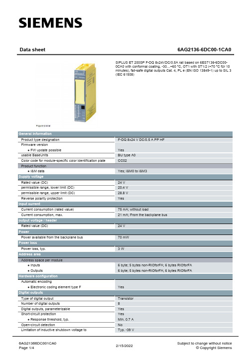
Data sheet
6AG2136-6DC00-1CA0
SIPLUS ET 200SP F-DQ 8x24VDC/0.5A rail based on 6ES7136-6DC000CA0 with conformal coating, -30…+60 °C, OT1 with ST1/2 (+70 °C für 10 minutes), fail-safe digital outputs Cat. 4, PL e (EN ISO 13849-1) up to SIL 3 (IEC 61508)
F-DQ 8x24 V DC/0.5 A PP HF
Yes BU type A0 CC02
Yes; I&M0 to I&M3
24 V 20.4 V 28.8 V Yes
75 mA; without load 21 mA; From the backplae; 5 bytes non-RIOforFA; 6 bytes RIOforFA 6 byte; 5 bytes non-RIOforFA; 6 bytes RIOforFA
0.5 A; note derating data in the manual 3 A; note derating data in the manual
3 A; note derating data in the manual 2.5 A; note derating data in the manual 2 A; note derating data in the manual 2 A; note derating information in the manual; only with configured slots to the left and right of the module
1734-ob8(模块)

3
2 8
5 6 7
10 1
Description
Description
1
Mounting Base1
6
RTB Removal Handle
2 Mechanical Keying (oranal Block (RTB)1
3 Module Wiring Diagram
This equipment is considered Group 1, Class A industrial equipment according to IEC/CISPR Publication 11. Without appropriate precautions, there may be potential difficulties ensuring electromagnetic compatibility in other environments due to conducted as well as radiated disturbance. This equipment is supplied as "open type" equipment. It must be mounted within an enclosure that is suitably designed for those specific environmental conditions that will be present and appropriately designed to prevent personal injury resulting from accessibility to live parts. The interior of the enclosure must be accessible only by the use of a tool. Subsequent sections of this publication may contain additional information regarding specific enclosure type ratings that are required to comply with certain product safety certifications.
CerberusECOFS18西门子消防产品介绍

标签可以直接粘 贴在施工图纸上
标记安装定位
FDO181 D7N8C396
Page 26
Cerberus ECO FS18产品特点 – 高效的编码标签安装调试方法
Page 27
内容
1 背景:品牌、定位、设计理念与应用 2 产品:完善的产品系列,满足主流应用需求 3 特点:可靠,智能,灵活,高效 4 总结:为客户创造价值
SinБайду номын сангаасeso™
(2008年12月发布)
FDO221-CN
Cerberus™ FD720
(2009年3月发布)
FS1120 FDT241-CN OP720-CN
M3
~ 65%
(主流市场)
BC80
FS1120 HI720-CN
Cerberus ECO FS18
(2009年6月发布)
FDO181
FC18 FC18R FDT181
由瑞士总部和中国专家共同组成的专职「SMART」研 发团队开发,采用全球领先的技术和系统架构,并遵 循西门子全球统一的严格质量标准。
Page 5
火灾报警细分目标市场与西门子产品线
市场份额(金额) 西门子已有产品
西门子新产品
M1 (高端)
~ 5%
M2 (中高端)
~ 30%
进口51 合资51 合资31
Page 24
Cerberus ECO FS18产品特点 – 使用高效
高效特性
控制器软件编址技术,自动读入回路中新连接设备,即时投用 创新的右键快捷菜单操作 可通过控制器编写用户程序 控制器接线端子均为插拔式,方便接线 高效的编码标签安装定位与调试方法
NI sbRIO-9627单板RIO OEM设备技术规格说明说明书
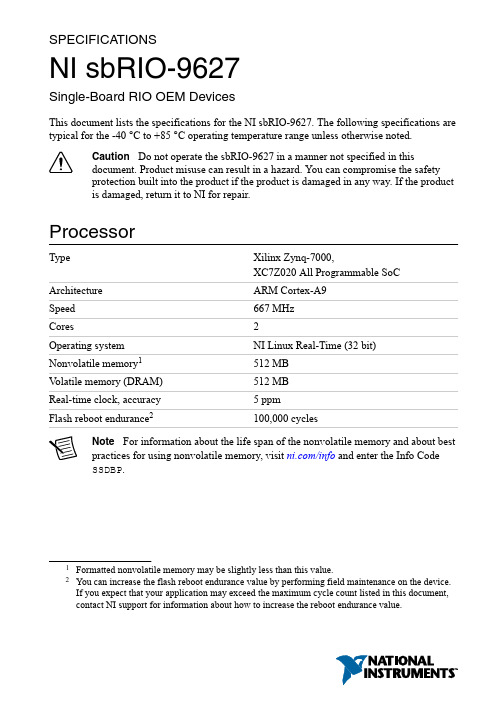
SPECIFICA TIONSNI sbRIO-9627Single-Board RIO OEM DevicesThis document lists the specifications for the NI sbRIO-9627. The following specifications are typical for the -40 °C to +85 °C operating temperature range unless otherwise noted.Caution Do not operate the sbRIO-9627 in a manner not specified in thisdocument. Product misuse can result in a hazard. You can compromise the safetyprotection built into the product if the product is damaged in any way. If the productis damaged, return it to NI for repair.ProcessorType Xilinx Zynq-7000,XC7Z020 All Programmable SoC Architecture ARM Cortex-A9Speed667 MHzCores2Operating system NI Linux Real-Time (32 bit)Nonvolatile memory1512 MBV olatile memory (DRAM)512 MBReal-time clock, accuracy 5 ppmFlash reboot endurance2100,000 cyclesNote For information about the life span of the nonvolatile memory and about bestpractices for using nonvolatile memory, visit /info and enter the Info CodeSSDBP.1Formatted nonvolatile memory may be slightly less than this value.2You can increase the flash reboot endurance value by performing field maintenance on the device.If you expect that your application may exceed the maximum cycle count listed in this document, contact NI support for information about how to increase the reboot endurance value.Operating SystemNote For minimum software support information, visit /info and enter theInfo Code swsupport.Supported operating system NI Linux Real-Time (32-bit)Minimum software requirementsApplication softwareLabVIEW LabVIEW 2015,LabVIEW 2015 Real-Time Module,LabVIEW 2015 FPGA ModuleEclipse Edition 2014C/C++ Development Tools forNI Linux Real-Time3Driver software NI CompactRIO Device Drivers August 2015 Reconfigurable FPGAType Xilinx Zynq-7000,XC7Z020 All Programmable SoCNumber of logic cells85,000Number of flip-flops106,400Number of 6-input LUTs53,200220Number of DSP slices(18 x 25 multipliers)Available block RAM560 KBNumber of DMA channels16Number of logical interrupts32Network/Ethernet PortNumber of interfacesFront Panel Ethernet 1 (Eth0)RMC Ethernet 1 (Eth1)3C/C++ Development Tools for NI Linux Real-Time is an optional interface for C/C++programming of the sbRIO-9627 processor. Visit /info and enter Info Code RIOCdev for more information about the C/C++ Development Tools for NI Linux Real-Time.2| | NI sbRIO-9627 SpecificationsNetwork interface10Base-T, 100Base-TX, and1000Base-T Ethernet4Compatibility IEEE 802.3Communication rates10 Mbps, 100 Mbps,1000 Mbps auto-negotiated, half-/full-duplex Maximum cabling distance100 m/segmentRS-232 (DTE) Serial PortNumber of interfacesOnboard RS-232 2 (Serial1, Serial2)RMC RS-232 via FPGA 3.3 V DIO 4 (Serial4, Serial5, Serial6, Serial7)Baud rate support ArbitraryMaximum baud rate230,400 bpsData bits5, 6, 7, 8Stop bits1, 2Parity Odd, Even, Mark, SpaceFlow control RTS/CTS, XON/XOFF, DTR/DSR, NoneRS-485 Serial PortNumber of interfacesOnboard RS-485 1 (Serial3)RMC RS-485 via FPGA 3.3 V DIO 2 (Serial8, Serial9)Maximum baud rate460,800 bpsData bits5, 6, 7, 8Stop bits1, 1.5, 2Parity Odd, Even, Mark, SpaceFlow control XON/XOFF4For revision D and earlier, 1000Base-T Ethernet link and communication is not guaranteed forprimary or secondary Ethernet ports below -20 °C. If you expect ambient temperatures below-20 °C, NI recommends using a 10/100 network infrastructure or assigning 10/100Mbpscommunication speeds to the Ethernet Adapter in NI Measurement & Automation Explorer(MAX).NI sbRIO-9627 Specifications| © National Instruments| 3Wire mode4-wire, 2-wire, 2-wire auto Isolation voltage, port to earth ground NoneEmbedded CANNumber of interfacesOnboard CAN 1 (CAN0)RMC CAN via FPGA 3.3 V DIO 1 (CAN1)Onboard CAN transceiver NXP PCA82C251T Maximum baud rate 1 MbpsMinimum baud rate10 kbpsUSB PortNumber of interfacesFront Panel USB Host 1 (USB0)RMC USB Host/Device 1 (USB1) Compatibility USB 2.0, Hi-Speed Maximum data rate480 Mb/sMaximum front panel USB current900 mASD Card SlotNumber of interfacesFront Panel SD 1 (SDIO0)RMC SD via FPGA 3.3 V DIO 1 (SDIO1)Supported Standards SD, SDHC5Front Panel SD ThroughputRead12.0 MB/s maximumWrite9.0 MB/s maximum5Both standard SD and microSD interfaces are supported.4| | NI sbRIO-9627 SpecificationsRMC SD via FPGA DIO ThroughputRead8.0 MB/s maximumWrite 6.5 MB/s maximumNote RMC SD has slower throughputs as the Xilinx Zynq-7000 requires SDinterfaces through the FPGA to operate at standard speed rather than at high speed.3.3 V Digital I/O on RMC ConnectorNumber of DIO channels96Maximum tested current per channel±3 mANote The performance of the RMC DIO pins is bounded by the FPGA, signalintegrity, the application timing requirements, and the RMC design. A general SPIapplication will typically be able to meet these requirements and achieve frequenciesof up to 10 MHz. For more information on using DIO to connect to RMCs, visit/info and enter the Info Code RMCDIO.Input logic levelsInput low voltage, V IL-0.3 V minimum; 0.8 V maximumInput high voltage, V IH 2.0 V minimum; 3.45 V maximumOutput logic levels2.4 V minimum;3.45 V maximumOutput high voltage, V OHwhen sourcing 3 mA0.0 V minimum; 0.4 V maximumOutput low voltage, V OLwhen sinking 3 mA3.3 V Digital I/O on 50-Pin IDC ConnectorNumber of DIO channels4Maximum tested current per channel±3 mAInput logic levelsInput low voltage, V IL-0.3 V minimum; 0.8 V maximumInput high voltage, V IH 2.0 V minimum; 5.25 V maximumNI sbRIO-9627 Specifications| © National Instruments| 5Output logic levelsOutput high voltage, V OH2.4 V minimum;3.45 V maximumwhen sourcing 3 mA0.0 V minimum; 0.4 V maximumOutput low voltage, V OLwhen sinking 3 mAAnalog Input CharacteristicsNumber of channels16 single-ended or 8 differential ADC resolution16 bitsMaximum aggregate sampling rate200 kS/sInput range±10 V, ±5 V, ±2 V, ±1 V Maximum working voltage (signal + common mode)10 V range±11 V5 V range±10.5 V2 V range±9 V1 V range±8.5 VInput impedancePowered on> 1 GΩ in parallel with 100 pFPowered off/overload 2.3 kΩ minimumOvervoltage protectionPowered on±25 V, for up to 2 AI pinsPowered off±15VAI accuracy6| | NI sbRIO-9627 SpecificationsGain drift 12 ppm of reading/°C Offset drift 4 ppm of range/°C AI noise10 V range 200 μVrms 5 V range 105 μVrms 2 V range 45 μVrms 1 V range 30 μVrmsINL ±64 ppm of range, maximum DNLNo missing codes guaranteed CMRR, DC to 60 Hz -80 dB Input bandwidth (-3 dB)540 kHz, typical Settling error (multichannel scanning)±60 ppm step size, typical Crosstalk (10 kHz)-70 dBTypical performanceFigure 1. Common Mode Rejection Ratio versus FrequencyC M R R (d B )Frequency (Hz)NI sbRIO-9627 Specifications | © National Instruments | 7Figure 2. Normalized Signal Amplitude versus FrequencyN o r m a l i z e d S i g n a l A m p l i t u d e (d B )Frequency (Hz)Figure 3. Settling Error versus Source ImpedanceE r r o r (p p m o f S t e p S i z e )Source Impedance (Ω)10010001000010000010000010000100010010Analog Output CharacteristicsNumber of channels 4DAC resolution16 bits8 | | NI sbRIO-9627 SpecificationsMaximum update rate6336 kS/sRange±10 VOverrange operating voltageMinimum10.3 VTypical10.6 VMaximum10.9 VOutput impedance0.4 Ω typicalCurrent drive±3 mA/channel maximumProtection Short-circuit to groundPower-on state70 VAO accuracyGain drift23 ppm of reading/°COffset drift 5.4 ppm of range/°CINL±194 ppm of range, maximumDNL±16 ppm of range, maximumCapacitive drive 1.5 nF, typicalSlew rate 3.7 V / μsec, typicalSettling time (100 pF load to 320 μV)FS step50 μs2 V step12 μs0.2 V step9 μs6This is the maximum update rate when running one AO channel in a loop with the FPGA top-level clock set to 40 MHz.7When the analog output initializes, a voltage glitch occurs for about 20 μs, peaking at 1.3 V,typical.8Range is 5 V.NI sbRIO-9627 Specifications| © National Instruments| 9CMOS BatteryNote The battery is user-replaceable. The NI sbRIO device ships with a BR1225coin cell battery from RAYOV AC, which is industrial-rated. Ensure that powerremains connected to the NI sbRIO device while you replace the battery so thattime-keeping is not disrupted. Refer to the Battery Replacement and Disposalsection for information about replacing the battery.10 yearsTypical battery life with power applied topower connectorTypical battery life in storage at 55 °C 2.5 years9Power Outputs on RMCCaution Exceeding the power limits may cause unpredictable device behavior.+5 V power outputOutput voltage 5 V ±5%Maximum current 1.5 AMaximum ripple and noise50 mV+3.3 V_AUX power outputOutput voltage 3.3 V ±5%Maximum current0.33 AMaximum ripple and noise50 mVFPGA_VIO power outputOutput voltage 3.3 V ±5%Maximum current0.33 AMaximum ripple and noise50 mVPower RequirementsThe NI sbRIO device requires a power supply connected either to the power connector or through the VIN_filtered pins through the RMC. Refer to the Powering On the NI sbRIO Device section in the NI sbRIO-9627 Getting Started Guide on /manuals for information about connecting the power supply. Refer to the NI sbRIO-9607/9627 RMC9Battery life may drop dramatically in extreme temperatures.10| | NI sbRIO-9627 SpecificationsDesign Guide on /manuals for more information about how to power the NI sbRIO device through the RMC.Caution Exceeding the power limits may cause unpredictable device behavior.Recommended power supply55 W, 30 VDC maximumPower supply voltage range9 VDC to 30 VDCReversed-voltage protection30 VDCPower consumption with RMC29 W maximumEnvironmentalCaution Clean the sbRIO-9627 with a soft, nonmetallic brush. Make sure that thedevice is completely dry and free from contaminants before returning it to service.-40 °C to 85 °C10Local ambient operating temperature neardevice (IEC 60068-2-1, IEC 60068-2-2)Maximum reported onboard sensor temperatureCPU/FPGA temperature98 °CPrimary System temperature85 °CSecondary System temperature85 °CTable 1. Component Maximum Case TemperatureThe sbRIO-9627 includes three onboard temperature monitoring sensors to simplify validation of a thermal solution by indicating thermal performance during validation and deployment.10If you expect ambient temperatures below -20 °C, NI recommends using a 10/100 network infrastructure or assigning 10/100Mbps communication speeds to the Ethernet Adapter in NI MAX.Refer to the Network/Ethernet Port section of this document for more information.11Use digital approach to ensure the on-chip temperature reading is below 98°C.NI sbRIO-9627 Specifications| © National Instruments| 11The sensors measure the CPU/FPGA junction temperature and printed circuit board temperatures that can be used to approximate the primary and secondary side local ambient temperatures. This approach is called digital validation. Alternatively, the traditional analog approach using thermocouples can be used to validate thermal performance. The digital approach is more accurate for determining the performance of the CPU/FPGA but is more conservative for determining the local ambient temperatures. NI recommends using digital validation.For digital validation, ensure that the reported CPU/FPGA, reported Primary System, and reported Secondary System temperatures do not exceed any of the maximum temperatures listed in this document. Thermal validation is complete if the reported temperatures are within specifications. For more information about how to access the onboard sensors, visit / info and enter the Info Code sbriosensors. If the reported Primary System temperature or reported Secondary System temperature exceed the maximum temperatures listed in this document then analog validation may be used for further verification.For analog validation, measure the local ambient temperature by placing thermocouples on both sides of the PCB, 5 mm (0.2 in.) from the board surface. Avoid placing thermocouples next to hot components such as the CPU/FPGA or near board edges, which can cause inaccurate temperature measurements. In addition to the local ambient temperature, the case temperature of the components should not exceed the recommended maximum case temperature.Note Some systems may require a heat sink or air flow to remain within themaximum allowed temperature ranges. You can mount the Thermal Kit forNI sbRIO-9607/9627/9637 (153901-02) heat spreader on the NI sbRIO device.Note The NI sbRIO device thermal performance is greatly influenced by severalfactors, including resource utilization, mounting, and adjacent power dissipation.These factors can substantially affect the achievable external ambient temperature atwhich the maximum local and reported temperatures are reached. NI recommendsadditional thermal design to remain within the maximum allowed temperatureranges. For information about and examples of environmental and design factors thatcan affect the thermal performance of NI sbRIO systems, visit /info and enterthe Info Code sbriocooling. For device-specific guidelines about enablingproper thermal design, refer to the NI sbRIO-9627 User Manual on /manuals.-40 °C to 85 °CStorage temperature(IEC 60068-2-1, IEC 60068-2-2)Operating humidity (IEC 60068-2-78)10% RH to 90% RH, noncondensing Storage humidity (IEC 60068-2-78)5% RH to 95% RH, noncondensing Maximum altitude5,000 mPollution Degree (IEC 60664)2The NI sbRIO device is intended for indoor use only.12| | NI sbRIO-9627 SpecificationsPhysical CharacteristicsWeight131.3 g (4.631 oz)Safety VoltagesConnect only voltages that are below these limits.V terminal to C terminal30 VDC maximum, Measurement Category I Measurement Category I is for measurements performed on circuits not directly connected to the electrical distribution system referred to as MAINS voltage. MAINS is a hazardous live electrical supply system that powers equipment. This category is for measurements of voltages from specially protected secondary circuits. Such voltage measurements include signal levels, special equipment, limited-energy parts of equipment, circuits powered by regulated low-voltage sources, and electronics.Caution Do not connect the sbRIO-9627 to signals or use for measurements withinMeasurement Categories II, III, or IV.Environmental ManagementNI is committed to designing and manufacturing products in an environmentally responsible manner. NI recognizes that eliminating certain hazardous substances from our products is beneficial to the environment and to NI customers.For additional environmental information, refer to the Minimize Our Environmental Impact web page at /environment. This page contains the environmental regulations and directives with which NI complies, as well as other environmental information not included in this document.Waste Electrical and Electronic Equipment (WEEE)EU Customers At the end of the product life cycle, all NI products must bedisposed of according to local laws and regulations. For more information abouthow to recycle NI products in your region, visit /environment/weee.Battery Replacement and DisposalBattery Directive This device contains a long-life coin cell battery. If you need toreplace it, use the Return Material Authorization (RMA) process or contact anNI sbRIO-9627 Specifications| © National Instruments| 13authorized National Instruments service representative. For more information aboutcompliance with the EU Battery Directive 2006/66/EC about Batteries andAccumulators and Waste Batteries and Accumulators, visit /environment/batterydirective.电子信息产品污染控制管理办法(中国RoHS)中国客户National Instruments符合中国电子信息产品中限制使用某些有害物质指令(RoHS)。
MT1260单点载重仪器平台集成平台说明书

M T 1260 L o a d C e l lMT1260 Single Point Load CellThe MT1260 load cell features: • OIML R60 C3 approval• NTEP 5000 III S/M approval• ATEX Zone 1/2 and 21/22 approvals • Off-center load compensation (R76)• 600x600 mm platform size • IP67 protection class • Passivated aluminum • 50-750kg capacity rangeThe MT1260 is the ideal solution for floor scales and smaller hoppers. Due to the low profile the integration into any system is easy. The broad capacity range and large platform size allows wide useage in indu-strial weighing applications.Off-Center CompensationOne load cell can be used to support a weighing platform and, due to the off-center load compensation, the MT1260 will weigh within tolerance regardless of Floor Scale, Tank WeighingMT1260 provides the best weighing performance for floor scales and hopper weighing in its capacity range. With a low profile design, cost optimization and an attractive product appearance MT1260 allows 50% static overload without compromising the weighing performance. The passivated aluminium provides good corrosion resistance suit-able for many industrial applications.2MT1260 Load Cell SpecificationsParameter Unit of measure SpecificationModel No.MT1260Rated capacity (R.C.)kg (lb, nominal)50 (110)75 (165)100 (220)150 (331)200 (441)250 (551)300 (661)500(1102)750(1654) Rated output mV/*****. 2 ± 0.2Zero load output%R.C.≤ 10Combined error 1) 2)%R.C.≤ 0.016Repeatability error%A.L. 3)≤ 0.01Creep, 30 minute%A.L. ≤ 0.0167Min. dead load output return (DR), 30 min%A.L. ≤ 0.0167Temperature effect onMin. dead loadOutput%R.C./°C (../°F)≤ 0.0014 (0.0008)Sensitivity 2)%A.L./°C (../°F)≤ 0.0007 (0.00036)Temperature rangeCompensated°C (°F)-10 ~ +40 (+14 ~ +104)Operating-40 ~ +65 (-40 ~ +150)Safe storage-40 ~ +80 (-40 ~ +176)OIML / Europeanapproval 4)OIML Cert. No.R60/2000-NL1-03.14European Cert. No.NMi TC5367Class C3nmax3000Vmin g8.31516.72533.341.75083125PLC0.7Humidity symbol NoneMin. dead load kg (lb)0 (0)Z3000NTEP approval 4)Number11-088Class III S, III Mnmax5000Vmin g (lb)5(0.011)7.5(0.017)10(0.022)15(0.033)20(0.044)25(0.055)30(0.066)50(0.11)70(0.17)Min. dead load kg (lb)0 (0)ATEX approval 4)Number, cat. 2KEMA 09ATEX0003 XNumber, cat. 3KEMA 09ATEX0004 XRatingII 2 G Ex ib IIC T4II 2 D Ex ibD 21 IP66 T135 °CII 3 G Ex nA II T4II 3 G Ex nL IIC T4II 3 D Ex tD A22 IP66 T135°CEntity parameters Ui/Un=20V, Ii=600mA, Pi=1.25W, Ci=5nF, Li=30μHExcitation voltageRecommendedV AC/DC5 ~ 15Max.20Terminal resistanceExcitationΩ410 ± 10Output350 ± 4Insulation resistance @50VDC MΩ> 5000Breakdown voltage V AC> 500MaterialSpring element AluminiumEnclosure NoneCable PVCProtectionType PottedIP rating IP 67NEMA rating NEMA 6/6PLoad limitSafe%R.C.150Ultimate300Safe dynamic load%R.C.70Fatigue life**********.> 1000000Direction of loading Beam**************.,nominal mm (in)0.3 (0.012)Weight, nominal kg (lb) 1.9 (4.2)Cable length m (ft) 2 (6.6)Barometric pressure effect on zero load output kg/kPa (lb/in.Hg)NoneSafe side load%R.C.100Overload protection NoneMounting screwGrade12.9Size/thread mm (in)M8x1.25Engaged length mm (in)20 (0.79)Torque, nominal N.m (ft-lb)25 (18)Max. platter size cm x cm (in x in)60 x 60 (24 x 24)Off center load error, R76-1%A.L./cm (../in)0.0032 (0.008)1) Error due to the combined effect of non-linearity and hysteresis2) Typical values only. The sum of errors due to combined error and temperature effect on sensitivity comply with the requirements of OIML R60 and NIST HB44.3) A.L. = Applied Load4)See certificate for complete information.METTLER TOLEDO MT1260 Single Point Load Cell©11/2019MT1260 Load Cell Dimensional Drawings mm [inch]METTLER TOLEDO Datasheet MT1260 Single Point Load Cell©11/20193MT1260 Load Cell Order InformationWeighing ElectronicsMETTLER TOLEDO offers a complete family of electronics from simple weighing to application solutions for filling, stock control, batching, formulation, counting, and checkweighing.Full ConnectivityMETTLER TOLEDO supplies various data communication interfaces that enable our sensors and instruments to communicate with your PLC, MES, or ERP systems.OIML ApprovalsThe MT1260 is provided with C3 approval acc. to OIML R60. Thus best weighing performance is guaranteed at all specified conditions. Benefit from METTLER TOLEDO experience.MT1260 Load Cell Cable ColoursVisit for more informationColour Function Green + Excitation Black – Excitation Red + Signal White – Signal Blue + Sense Brown – Sense Yellow + ShieldDescriptionItem No.Load cell, model no. MT1260-50kg 2m Cable 71201844Load cell, model no. MT1260-75kg 2m Cable 71201845Load cell, model no. MT1260-100kg 2m Cable 71201846Load cell, model no. MT1260-150kg 2m Cable 71201847Load cell, model no. MT1260-200kg 2m Cable 71201848Load cell, model no. MT1260-250kg 2m Cable 71201849Load cell, model no. MT1260-300kg 2m Cable 71207455Load cell, model no. MT1260-500kg 2m Cable 71207456Load cell, model no. MT1260-750kg 2m Cable 71209936Load cell, model no. MT1260-50kg 6m Cable 72208484Load cell, model no. MT1260-75kg 6m Cable 72208485Load cell, model no. MT1260-100kg 6m Cable 72208486Load cell, model no. MT1260-150kg 6m Cable 72208487Load cell, model no. MT1260-200kg 6m Cable 72208488Load cell, model no. MT1260-250kg 6m Cable 72208489Load cell, model no. MT1260-300kg 6m Cable 72208490Load cell, model no. MT1260-500kg 6m Cable 72208491Load cell, model no. MT1260-750kg 6m Cable72208492Bolded entries are stockedOur extensive service network is among the best in the world and ensures maximum availability and service life of your product.METTLER TOLEDO Group Industrial DivisionLocal contact: /contactsSubject to technical changes© 11/2019 METTLER TOLEDO. All rights reserved Document No. 44099826 A MarCom Industrial。
LEA-6_ProductSummary_(GPS.G6-HW-09002)
GPS
locate, communicate, accelerate
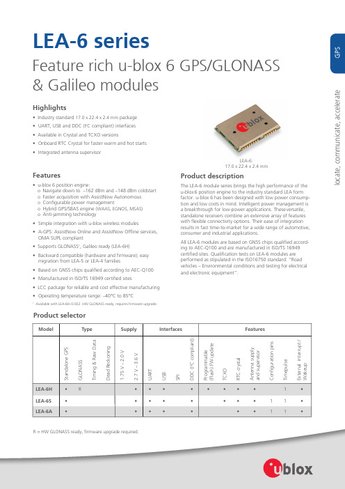
LEA-6 series
Feature rich u-blox 6 GPS/GLONASS & Galileo modules
Highlights
• Industry standard 17.0 x 22.4 x 2.4 mm package • UART, USB and DDC (I2C compliant) interfaces • Available in Crystal and TCXO versions • Onboard RTC Crystal for faster warm and hot starts • Integrated antenna supervisor
The information contained herein is provided “as is”. No warranty of any kind, either express or implied, is made in relation to the accuracy, reliability, fitness for a particular purpose or content of this document. This document may be revised by u-blox at any time. For most recent documents, please visit .
M-System 产品服务政策说明书
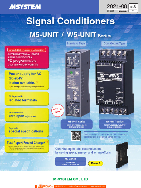
Signal ConditionersULTRA-SLIMSIGNAL CONDITIONERSM6 SeriesACTUALSIZEStandard TypeDual Output TypeTERMINAL BLOCK DUAL OUTPUTSIGNAL CONDITIONERSW5-UNIT SeriesSUPER-MINI TERMINAL BLOCKSIGNAL CONDITIONERSM5-UNIT SeriesScheduled to be released in 2021SUPER-MINI TERMINAL BLOCK SIGNAL CONDITIONERSModel: M5XU/M5XV/M5XTRPC-programmableM5-UNIT /W5-UNIT SeriesProvided withzero span adjustmentSupportsspecial specifications Test Report Free of Charge !(*2)(*2)All types with isolated terminalsIf you need a test report, please contact your local distributor.They will send it to you free of charge (pdf version only. Notavailable for all models).2021-08EC-Z224Rev.01500694056 222 38 18*********************SEN TRONIC AGSUPER-MINI TERMINAL BLOCK SIGNAL CONDITIONERSTERMINAL BLOCK DUAL OUTPUT SIGNAL CONDITIONERSW5VS94mm25 mm (0.98 in.)WidthPC programmable modelsare also available.The M5XU, M5XV, and M5XTRmodels allow PC settings.Low ProfileM5-UNIT SeriesACTUAL SIZEM5VS94 mm 45 mm (1.77 in.)WidthSignal splitters with isolated dual outputsFour-port isolation between the input, output 1, output 2, and power supply.Profile : 41 mm (1.61 in.)W5 models can be installed on boards with a shallow depth.Power supply for AC (85-264V) is also available.Supporting 85-264 V AC, 24 V DC, 11-27 V DC, 110 V DC.Low Profile Signal SplittersW5-UNIT SeriesPower supply for AC(85-264V) is also available.Supporting 85-264 V AC, 24 V DC.ACTUAL SIZEThe M5 Seriers offers low-profile terminal block style.All models can be freely mounted onto thin panels.The W5 Series offers low-profile signal splitters with isolated dual outputs.(3.70 in.)(3.70 in.)(*1)(*1) CE marking is not available depending on the model.2(*1)(*1) CE marking is not available depending on the model.terminal coveropenDepending on the model.Depending on the model.Isolation and power supplySpecifications may vary depending on the model.For details, see the datasheet.Power supplyPower supplycircuitInput circuit Output circuitInput signalOutput signalSpecifications may vary depending on the model.For details, see the datasheet.AC power supply: 85-264 V ACDC power supply: 24 V DC, 11-27 V DC, and 110 V DC AC power supply: 85-264 V AC DC power supply: 24 V DCPower supplyPower supply circuitInput circuitOutput-1 signal Output-2circuitOutput-2signalInput signalNo. of models bearing CE marking : 10Structure: Low-profile terminal blockConnections: M3.5 screw terminals Input: See List of Models Output: See the datasheet Installation: DIN rail mounting 14No. of models bearing CE marking : 7Terminal coverTerminal coverTerminal coverDepthThe openable terminal cover engraved with the terminal numbers andconnection guide prevents wiring mistakes and the loss of the cover.No. of models:8No. of models:Terminal blockstructure Three-port isolationAC DCPOWEREDDielectric strength: 2000 V AC @ 1 min.(with DC power supply)Dielectric strength: 1500 V AC @ 1 min.(with AC power supply)Three-port isolationanywhere.Terminal block structure Structure: Low-profile terminal block Connections: M3.5 screw terminals (Input)M3 screw terminals (Output and power supply)Input: See List of Models Output: See the datasheet Installation: DIN rail mountingIsolation and power supplyFour-port isolationDielectric strength: 2000 V AC @ 1 min.(Between input, output 1, output 2, power supply, and ground)Dielectric strength: 1500 V AC @ 1 min.(Between output 1 and output 2)Output-1circuit Four-port isolationAC DCPOWERED41 mm (1.61 in.)Depth41 mm (1.61 in.)Main SpecificationsMain Specifications3Isolators & Sensor InputsPower TransducersIsolators & Sensor InputsFrequency I/O Products Line upFeatures of M5-UNIT Series4056 222 38 18*********************SEN TRONICAGElectronic circuit specially designed for the M5 SeriesToroidal transformer Ceramic capacitorsSeat transformerSIGNAL TRANSMITTERSIGNAL TRANSMITTER (narrow span input)Model: M5VSModel: M5VF2Model: M5VSHModel: M5MVSIGNAL TRANSMITTER(high speed response 30μs.)A toroidal transformer with a donut-shaped core is anindispensable part of an efficient and high-speed response.The M5VS circuit is an efficient electronic circuit designed tooperate with the minimum number of parts without compromising performance and quality.With the ultra-slim sheet transformer made from a printed circuit board, the M5VSH has achieved a dielectric strength of 2000 V AC without taking up much space.The M5MV is a signal transmitter incorporating an electric circuit based on the electric circuit design of the M5VS so that the inputsection can handle minute signals. Also, as with the M5VS, the AC power supply does not usealuminum electrolytic capacitors.SIGNAL TRANSMITTER(high dielectric strength)Economical DC input signal transmitterSignal transmitter with ultra-fast 30μs response speed.Signal transmitter with high dielectric strength that withstands 2000 V ACSignal transmitter suitable for minute signal input5Optional specifications are available to meet various requirements, including coating designation. If you want to specify an option, write “/ Q” at the end of the order code. Then enter the optional specifications separately from the order code.Optional Specifications /C01/V01Optional Specifications code (example)Multi-turn potentiometer for fine adjustment Stainless steel screws Standard potentiometer Nickel-plated iron screws• The presence or absence of optional specifications and the supported content differ depending on the model. For details, see the datasheet.SPECIFICATIONS OF OPTION: Q(multiple selections)COATING/C01: Silicone coating/C02: Polyurethane coating /C03: Rubber coating ADJUSTMENT/V01: Multi-turn fine adjustment /VN : Sealed adjustment holes TERMINAL SCREW MATERIAL /S01: Stainless steelModel : M5VS- -/QOptional SpecificationsOrder code (example)INPUT OUTPUT POWER INPUT blank : none/Q : Option other than the aboveOPTIONS12346products of which we changed the design.Our Quality Assurance Dept. conducts a prototype evaluation before releasing a new product. We validate the products based on the various regulations / standards and the company standards mainly classified into an EMC (*4) test as a part of the evaluation test. Our anechoic chamberused for the EMC test is certified and registered by the official body (VCCI (*5)and we conduct an official test instead of a simplified test.No additional chargesM-System also respondsquickly to technical inquiries.M-System will standardize special specifications.Inquiries are answered promptly.The special specifications you ordered will be standardized in sequence.Various special specifications (request examples from customers)The range does not match with that of the standard specificationWe want to combine with the special sensorDifferent power supply voltageWe want an external volume• For details, contact M-System through the hotline.The Design Department needs to conduct a technical examination to see whether the special specifications you have inquired about can be manufactured.M-System responds to you with a technical review as soon as possible.We will standardize the special specification items,beginning with the ones most requested. Once they arestandardized, you will no longer need troublesome meetings or specification check when you place an order.EMC test required by the EMC directiveAnechoic chamber certified andregistered by the official body (VCCI (*5))A large shielded room of 6 m x 6 mwhere multiple tests can be conducted simultaneouslyEMC (Electro Magnetic Compatibility): Tests to check the effect by applying an electromagnetic noise toa device and to measure the electromagnetic wave and conductive common mode noise emitted from the device.VCCI (Voluntary Control Council for Interference by information technology equipment): Formerlyknown as Voluntary Control Council for Information Technology Equipment. An industry organization in Japan that discusses the regulations on the radio waves emitted from the information technology equipmentEvaluation testThe EMC test required for M-System to acquire the CE marking has the following test items and all of them are conducted by our own facility at Kyoto Techno Center (Kizugawa-City, Kyoto).We offer an enormous selection of signalconditioners and remote I/Os, power monitors, paperless recorders, panel meters, surgesuppressors and valve actuators, and even that may not be enough for your particular needs. But do not give up easily. Just ask us. We continue to work toward full product offerings with special specifications without additional charge, starting with major product series. In addition, we put our effort to make them into standard selections so that they are more easily accessible to you and everyone else in the future.We want to set the ranges of input signal and output signal to the ones not included in the existing code.We want to use the power supply compatible with the special CVCF(constant voltage and constant frequency unit).We want to match a marine power supply.We want to attach the volume toadjust the bias of the ratio conditioner onto the control panel surface.We want to combine with special sensor or thermistor not included in the standard.The special specification example which the legs of a leaded part are reinforced with a special kind of resin for the vibration countermeasure.We strive toward complete offerings with special specification products.(*4)(*5)7CUSTOMER FIRSTM-System Service PoliciesContinued Products Availability1Special specification products can be supplied without additional charge for major product series, except for those requiring excessive labor or materials.We are putting our effort into expansion of the scope of Special Specifications Service to all of our products. Special Specification Service will be available to more product series in the future.Special Specifications Service with no extra charge3During the service period of 36 months from the date of purchase, Special Repair Service47.5 mm (0.30 in.)M6 SeriesUltra-Slim Signal ConditionersFor detailed terms and conditions applicable to each specific product, consult M-System.All M-System’s products and services are provided outside Japan through M-System’s authorized distributors. M-System is trying to enhance the customer satisfaction with following 5 service policies. As to the terms and conditions of a specific service, consult M-System for details.Power supply for AC (100-240V) is also available (*6).Supporting 24 V DC, 100 - 240 VAC .(Only the M6xYV, M6xXU, M6xVS models accept AC power supply.)Extra Performance for Ultra-slim ConstructionThe ultra-slim M6 Series has achieved 2000 V AC isolation with marginal dielectric strength. Despite its ultra-slim housing, the allowable load resistance is 550Ω for 4-20 mA DC output. It has an energy-saving design that does not bother users with heat generation even if M6 Series units are closely mounted in the case of high-density installation.Ultra-slim Signal ConditionersUltra-slim housings of only 5.9 mm (0.23 in.) wide (M6D and M6S series models)Selectable Connection StylesTension-clamp, screw terminal, or Euro terminal styleScan the target 2D code for a list of M6 series models.5.9 mm (0.23 in.)Tension-ClampM6S Series Screw terminalM6N Series Euro terminalM6D Series5.9 mm (0.23 in.)056 222 38 18*********************SEN TRONIC AG。
intel cpu型号大全

intel cpu型号大全2009年12月24日星期四 15:12intel cpu型号大全按照处理器支持的平台来分,Intel处理器可分为台式机处理器、笔记本电脑处理器以及工作站/服务器处理器三大类;下面我们将根据这一分类为大家详细介绍不同处理器名称的含义与规格。
由于Intel产品线跨度很长,不少过往产品已经完全或基本被市场淘汰(比如奔腾III和赛扬II),为了方便起见,我们的介绍也主要围绕P4推出后Intel发布的处理器产品展开。
台式机处理器Pentium 4(P4)第一款P4处理器是Intel在2000年11月21日发布的P4 1.5GHz处理器,从那以后到现在近四年的时间里,P4处理器随着规格的不断变化已经发展成了具有近10种不同规格的处理器家族。
在这里面,“P4 XXGHz”是最简单的P4处理器型号。
这其中,早期的P4处理器采用了Willamette核心和Socket 423封装,具256KB二级缓存以及400MHz前端总线。
之后由于接口类型的改变,又出现了采用illamette核心和Socket478封装的 P4产品。
而目前我们所说的“P4”一般是指采用了Northwood核心、具有400MHz前端总线以及512KB二级缓存、基于Socket 478封装的P4处理器。
虽然规格上不一样,不过这些处理器的名称都采用了“P4 XXGHz”的命名方式,比如P4 1.5GHz、P4 1.8GHz、P4 2.4GHz。
Pentium 4 A(P4 A)有了P4作为型号基准,那么P4 A就不难理解了。
在基于Willamette核心的P4处理器推出后不久,Intel为了提升处理器性能,发布了采用Northwood 核心、具有 400MHz前端总线以及512KB二级缓存的新一代P4。
由于这两种处理器在部分频率上发生了重叠,为了便于消费者辨识,Intel就在出现重叠的、基于Northwood核心的P4处理器后面增加一个大写字母“A”以示区别,于是就诞生了P4 1.8A GHz、P4 2.0A GHz这样的处理器产品。
美国电气设备 ProLine UL 67 面板板和断言器说明书
—US C ATALOGProLineUL 67 Panelboards and breakers—Table of contents04D escription and features 07C atalog number guide andpanelboard configurator 08Order codes09Breakers14Accessories15A pproximate dimensions 18T echnical specifications 19S eries UL ratings21 B reaker placement guide4PROLINE PANELBOARD AND BREAKERS—ProLine panelboard and breakers descriptionElectrical• UL File #E499134• UL 67• 225 A and 400 A• 42 and 84 circuits (12- and 24-circuit types upon request)• Panelboard rating 480Y/277 V AC, branch breaker rating480Y/277 V AC up to 35 A and 240 V AC up to 100 A• Up to 35 kAIC series rating @240 V AC• Up to 30 kAIC series rating @480Y/277 V AC• Single- or double-ended (feed-through)• 1 A to 100 A branch breakers• Fully rated sub-fed lugs or breaker• NEMA 1 enclosure optionalFeatures• Breakers UL current-limiting• Fully coordinated• IP20 touch-safe• Pluggable breaker with non-energized bolt-on screwElectrical• Current-limiting according to UL 489• Up to 240 V and 480Y/277 V AC• Stand-alone rating up to 50 kA (depending on breaker type)• K trip curve• 1 A to 100 AFeatures• Contact position window• Independent thermal and magnetic trip units• Branch breakers with separated electrical (plug-in)and mechanical (bolt-on) connectionThe ProLine branch circuit breakers are the industry’s first UL listedcurrent-limiting breakers to be used in a panelboard application.The ProLine panelboard is the electrical industry’s first current-limiting, touch-safe and fully coordinated UL 67 panelboard.5DESCRIPTION AND FEATURES —Panelboard featuresMain breakerMain incoming connections• Lugs• Breaker• Studs Touch-safe main cover• Removable maincover with integratedneutral terminals• Access to neutralconnections withoutremoving coverNeutral bar assembly (with touch-safe cover)Branch breakers• 1 A to 100 A @ 240 V AC•1 A to 35 A @ 480Y/277 V AC6PROLINE PANELBOARD AND BREAKERS—Breaker featuresStable busbar design for high withstand ratings• Busbar designed with more surface area than typical panelboard busbar• Busbar encased in resin to aid stabilization in case of a faultNon-energizedmechanicalbolt-onconnection Electrical plug-in connectionPluggable with non-energized bolt-on connectionBreaker bus connection pointNon-energizedbolt-on pointEncased busbarsRecessedtouch-safebreakerconnectionInsulatingresin71 12-circuit version not available with double incoming.C ATA LO G N U M B ER G U IDE A N D PA N EL B OA R D CO N FI G U R ATO R —Catalog number guide and panelboard configurator1–2 – Product prefix Proline order code explanationA complete Proline part number consists of 14 characters.All characters shown are mandatory.4-5– Circuits 11 – Type13-14 – Enclosure—1–2 – Product prefix —3 – Phases —4-5 – Circuits —8-10 – AmpacityCode —Mandatory characters—6 – Incoming —13-14 – Enclosure —7 – Main —11 – Type—12 – Neutral7 – Main8PROLINE PANELBOARD AND BREAKERS—ProLine panelboard standard order codesCatalog number Description9BREAKERS —Branch breakersSUP200M seriesRated current I n Rated current I nSUP201MSUP202MSUP203MPROLINE PANELBOARD AND BREAKERSRated current I n Rated current I n Available with ring tongue terminals upon request.S801U S802U S803U11BREAKERS —Bus connectors for branch breakersCatalog number DescriptionPLBCS2PLBCS8L2R PLBCS8L1L PLBCS8L3RPLBCS8L2L PLBCS8DL1PLBCS8L3LPLBCS8DL2PLBCS8L1R PLBCS8DL312PROLINE PANELBOARD AND BREAKERS—ProLine breakers 120, 208, 240 V AC (factory-assembled with bus connector)PLU700M120/208/240 V ACK curve, 1-poleK curve, 2-poleK curve, 3-polePLU701MPLU702M-K60LPLU703M-K100RPLU703M13480Y/277 V ACK curve, 1-poleK curve, 2-pole K curve, 3-poleBREAKERS —ProLine breakers 480Y /277 V AC, UL 489PLU700M14PROLINE PANELBOARD AND BREAKERS—Accessories — panelboardPanelboard chassis hole bus coverDescriptionCatalog numberNeutral and ground bar assembliesDescriptionCatalog numberNeutral/ground lugsDescriptionCatalog numberPLBUSCVRMain and sub-feed lugsLugs for incoming and outgoing connectionsDescriptionCatalog numberPL350MECLUGMains cover (incomer and neutral lugs)Description Catalog numberPLMCVR15—Approximate dimensionsPanelboards single-ended and double-ended42-Circuit, single-endedDimensions in inches.84-Circuit, single-ended42-Circuit, double-endedACCE SSO R I E S , A PPR OX I M ATE D I M ENSI O NS16PROLINE PANELBOARD AND BREAKERS PLU700M1 A–50 A—Approximate dimensionsPL700 breakersDimensions in inches.1.057PLU700M25 A L/R - 70 A L/RPROLINE PANELBOARD AND BREAKERS 17A PPR OX I M ATE D I M ENSI ONS 0.199PLU700M 80 A - 100 A—Approximate dimensions PL700 breakersDimensions in inches.18PROLINE PANELBOARD AND BREAKERS—Technical specificationsSUP200M, PLU700M, S800U and PL700-K breakersItem SUP200M/PLU700M SUP200M/PLU700M S800U/PL700-K (L) S800U/PL700-K (R)UL ratings489489489 Number of poles1, 2, 31, 2, 31, 2, 3 Tripping characteristic K K K Rated currents 1 to 35 A40 A, 50 A25 A to 70 A1, 80 to 100 A2 Minimum operating voltage12 V12 V12 V UL rated voltage and interrupting capacityStand-alone short circuit current rating 14 kA 10 kA 30 kA: Single pole50 kA: Multi-poleFrequency50/60 Hz50/60 Hz50/60 Hz Rated voltage480Y/277 V AC240 V AC240 V AC Protection category IP 20IP 20 IP 20 Main terminalsWire size18–16 AWG/13.3 in-lbs.18–4 AWG/0.75–25 mm225–1 AWG14–10 AWG/17.7 in-lbs.8–4 AWG/39.8 in-lbs.Torque25 in-lbs/2.8 Nm25 in-lbs/2.8 Nm35 in-lbs./4 Nm Tool#2 Posidrive#2 Posidrive#2 Posidrive Service life at rated load6,000 operations6,000 operations6,000 operations20,000 operations (Mechanical endurance)20,000 operations(Mechanical endurance)—Ambient temperaturesMinimum-25 °C -13 °F-25 °C -13 °F-25 °C -13 °F Maximum+55 °C 131 °F+55 °C 131 °F60 °C 140 °F Storage temperaturesMinimum-40 °C -40 °F-40 °C -40 °F-40 °C -40 °F Maximum70 °C 158 °F70 °C 158 °F70 °C 158 °FShock resistance25 g minimum of 2 impacts,shock duration of 13 ms 25 g minimum of 2 impacts,shock duration of 13 ms—Vibration resistance 5 g, 20 cycles, 5 Hz,150 Hz at 0.8 ln 5 g, 20 cycles, 5 Hz,150 Hz at 0.8 ln—1 60 A/70 A have different dimensions.2 80 A/90 A/100 A available as “R” only and have double stab adapters.PROLINE PANELBOARD AND BREAKERS19TECH N I C A L SPECI FI C ATI O NS, SER I E S U L R ATI N G S—Series UL ratingsSUP200M MCBs with SACE® Tmax® XT MCCBsMain breaker Branch breaker Interrupting rating Type Amps Poles Type, trip curve Amps Poles Rms sym. A V AC Phase20PROLINE PANELBOARD AND BREAKERS—Breaker placement guide PLU701MPLU702M-K60L PLU703M-K100RPLU700M 1 A-50 A (1P/2P/3P)PLU700M"L" 25 A-70 A (1P/2P/3P)PLU700M 1 A-50 A (1P/2P/3P)PLU700M"L" 25 A-50 A (1P/2P/3P)PLU700M 1 A-50 A (1P/2P/3P)PLU700M"R" 25 A-70 A (1P/2P/3P)PLU700M"R" 80A/90A/100A (1P/2P/3P)PLU700M 1 A-50 A (1P/2P/3P)PLU700M"L" 25 A-70 A (1P/2P/3P)PLU700M 1 A-50 A (1P/2P/3P)PLU700M"R" 25 A-50 A (1P/2P/3P)PLU700M 1 A-50 A (1P/2P/3P)PLU700M"R" 25 A-70 A (1P/2P/3P)PLU700M"R" 80A/90A/100A (1P/2P/3P)PLU703MNotes:• PLU70XM-R and L have differentstab adapter position dimensions(see dimension drawings)• PLU70XM-R 80 A/90 A/100 A-Have double stab adapters-Are available as R onlySER I E S U L R ATI N G S, B R E A K ER PL ACEM ENT G U I D EPROLINE PANELBOARD AND BREAKERS21—Notes22PROLINE PANELBOARD AND BREAKERS —We reserve the right to make technical changes or modify the contents of this document without prior notice. With regard to purchase orders, the agreed particulars shall prevail. ABB Inc. does not acceptany r esponsibility whatsoever for potential errors or possible lack of information in this document.We reserve all rights in this document and in thesubject matter and illustrations contained therein.Any reproduction or utilization of its contents – inwhole or in parts – is forbidden without prior written consent of ABB Inc.Copyright© 2022 ABB Inc.All rights reserved1S X U 400139C 0201 R E V .D A U G U S T 2022—ABB Inc.Electrification860 Ridge Lake Blvd.Memphis, TN 38120/lowvoltageCustomer Service: 800-816-78097:00 a.m. - 5:30 p.m., CST, Monday-Friday ********************.comTechnical Support: 888-385-1221, Option 17:00 a.m. - 5:00 p.m., CST, Monday-Friday *******************.com。
NXP SCM-i.MX 6 Series Yocto Linux 用户指南说明书
© 2017 NXP B.V.SCM-i.MX 6 Series Yocto Linux User'sGuide1. IntroductionThe NXP SCM Linux BSP (Board Support Package) leverages the existing i.MX 6 Linux BSP release L4.1.15-2.0.0. The i.MX Linux BSP is a collection of binary files, source code, and support files that can be used to create a U-Boot bootloader, a Linux kernel image, and a root file system. The Yocto Project is the framework of choice to build the images described in this document, although other methods can be also used.The purpose of this document is to explain how to build an image and install the Linux BSP using the Yocto Project build environment on the SCM-i.MX 6Dual/Quad Quick Start (QWKS) board and the SCM-i.MX 6SoloX Evaluation Board (EVB). This release supports these SCM-i.MX 6 Series boards:• Quick Start Board for SCM-i.MX 6Dual/6Quad (QWKS-SCMIMX6DQ)• Evaluation Board for SCM-i.MX 6SoloX (EVB-SCMIMX6SX)NXP Semiconductors Document Number: SCMIMX6LRNUGUser's GuideRev. L4.1.15-2.0.0-ga , 04/2017Contents1. Introduction........................................................................ 1 1.1. Supporting documents ............................................ 22. Enabling Linux OS for SCM-i.MX 6Dual/6Quad/SoloX .. 2 2.1. Host setup ............................................................... 2 2.2. Host packages ......................................................... 23.Building Linux OS for SCM i.MX platforms .................... 3 3.1. Setting up the Repo utility ...................................... 3 3.2. Installing Yocto Project layers ................................ 3 3.3. Building the Yocto image ....................................... 4 3.4. Choosing a graphical back end ............................... 4 4. Deploying the image .......................................................... 5 4.1. Flashing the SD card image .................................... 5 4.2. MFGTool (Manufacturing Tool) ............................ 6 5. Specifying displays ............................................................ 6 6. Reset and boot switch configuration .................................. 7 6.1. Boot switch settings for QWKS SCM-i.MX 6D/Q . 7 6.2. Boot switch settings for EVB SCM-i.MX 6SoloX . 8 7. SCM uboot and kernel repos .............................................. 8 8. References.......................................................................... 8 9.Revision history (9)Enabling Linux OS for SCM-i.MX 6Dual/6Quad/SoloX1.1. Supporting documentsThese documents provide additional information and can be found at the NXP webpage (L4.1.15-2.0.0_LINUX_DOCS):•i.MX Linux® Release Notes—Provides the release information.•i.MX Linux® User's Guide—Contains the information on installing the U-Boot and Linux OS and using the i.MX-specific features.•i.MX Yocto Project User's Guide—Contains the instructions for setting up and building the Linux OS in the Yocto Project.•i.MX Linux®Reference Manual—Contains the information about the Linux drivers for i.MX.•i.MX BSP Porting Guide—Contains the instructions to port the BSP to a new board.These quick start guides contain basic information about the board and its setup:•QWKS board for SCM-i.MX 6D/Q Quick Start Guide•Evaluation board for SCM-i.MX 6SoloX Quick Start Guide2. Enabling Linux OS for SCM-i.MX 6Dual/6Quad/SoloXThis section describes how to obtain the SCM-related build environment for Yocto. This assumes that you are familiar with the standard i.MX Yocto Linux OS BSP environment and build process. If you are not familiar with this process, see the NXP Yocto Project User’s Guide (available at L4.1.15-2.0.0_LINUX_DOCS).2.1. Host setupTo get the Yocto Project expected behavior on a Linux OS host machine, install the packages and utilities described below. The hard disk space required on the host machine is an important consideration. For example, when building on a machine running Ubuntu, the minimum hard disk space required is about 50 GB for the X11 backend. It is recommended that at least 120 GB is provided, which is enough to compile any backend.The minimum recommended Ubuntu version is 14.04, but the builds for dizzy work on 12.04 (or later). Earlier versions may cause the Yocto Project build setup to fail, because it requires python versions only available on Ubuntu 12.04 (or later). See the Yocto Project reference manual for more information.2.2. Host packagesThe Yocto Project build requires that the packages documented under the Yocto Project are installed for the build. Visit the Yocto Project Quick Start at /docs/current/yocto-project-qs/yocto-project-qs.html and check for the packages that must be installed on your build machine.The essential Yocto Project host packages are:$ sudo apt-get install gawk wget git-core diffstat unzip texinfo gcc-multilib build-essential chrpath socat libsdl1.2-devThe i.MX layers’ host packages for the Ubuntu 12.04 (or 14.04) host setup are:$ sudo apt-get install libsdl1.2-dev xterm sed cvs subversion coreutils texi2html docbook-utils python-pysqlite2 help2man make gcc g++ desktop-file-utils libgl1-mesa-dev libglu1-mesa-dev mercurial autoconf automake groff curl lzop asciidocThe i.MX layers’ host packages for the Ubuntu 12.04 host setup are:$ sudo apt-get install uboot-mkimageThe i.MX layers’ host packages for the Ubuntu 14.04 host s etup are:$ sudo apt-get install u-boot-toolsThe configuration tool uses the default version of grep that is on your build machine. If there is a different version of grep in your path, it may cause the builds to fail. One workaround is to rename the special versi on to something not containing “grep”.3. Building Linux OS for SCM i.MX platforms3.1. Setting up the Repo utilityRepo is a tool built on top of GIT, which makes it easier to manage projects that contain multiple repositories that do not have to be on the same server. Repo complements the layered nature of the Yocto Project very well, making it easier for customers to add their own layers to the BSP.To install the Repo utility, perform these steps:1.Create a bin folder in the home directory.$ mkdir ~/bin (this step may not be needed if the bin folder already exists)$ curl /git-repo-downloads/repo > ~/bin/repo$ chmod a+x ~/bin/repo2.Add this line to the .bashrc file to ensure that the ~/bin folder is in your PATH variable:$ export PATH=~/bin:$PATH3.2. Installing Yocto Project layersAll the SCM-related changes are collected in the new meta-nxp-imx-scm layer, which is obtained through the Repo sync pointing to the corresponding scm-imx branch.Make sure that GIT is set up properly with these commands:$ git config --global "Your Name"$ git config --global user.email "Your Email"$ git config --listThe NXP Yocto Project BSP Release directory contains the sources directory, which contains the recipes used to build, one (or more) build directories, and a set of scripts used to set up the environment. The recipes used to build the project come from both the community and NXP. The Yocto Project layers are downloaded to the sources directory. This sets up the recipes that are used to build the project. The following code snippets show how to set up the SCM L4.1.15-2.0.0_ga Yocto environment for the SCM-i.MX 6 QWKS board and the evaluation board. In this example, a directory called fsl-arm-yocto-bsp is created for the project. Any name can be used instead of this.Building Linux OS for SCM i.MX platforms3.2.1. SCM-i.MX 6D/Q quick start board$ mkdir fsl-arm-yocto-bsp$ cd fsl-arm-yocto-bsp$ repo init -u git:///imx/fsl-arm-yocto-bsp.git -b imx-4.1-krogoth -m scm-imx-4.1.15-2.0.0.xml$ repo sync3.2.2. SCM-i.MX 6SoloX evaluation board$ mkdir my-evb_6sxscm-yocto-bsp$ cd my-evb_6sxscm-yocto-bsp$ repo init -u git:///imx/fsl-arm-yocto-bsp.git -b imx-4.1-krogoth -m scm-imx-4.1.15-2.0.0.xml$ repo sync3.3. Building the Yocto imageNote that the quick start board for SCM-i.MX 6D/Q and the evaluation board for SCM-i.MX 6SoloX are commercially available with a 1 GB LPDDR2 PoP memory configuration.This release supports the imx6dqscm-1gb-qwks, imx6dqscm-1gb-qwks-rev3, and imx6sxscm-1gb-evb. Set the machine configuration in MACHINE= in the following section.3.3.1. Choosing a machineChoose the machine configuration that matches your reference board.•imx6dqscm-1gb-qwks (QWKS board for SCM-i.MX 6DQ with 1 GB LPDDR2 PoP)•imx6dqscm-1gb-qwks-rev3 (QWKS board Rev C for SCM-i.MX 6DQ with 1GB LPDDR2 PoP) •imx6sxscm-1gb-evb (EVB for SCM-i.MX 6SX with 1 GB LPDDR2 PoP)3.4. Choosing a graphical back endBefore the setup, choose a graphical back end. The default is X11.Choose one of these graphical back ends:•X11•Wayland: using the Weston compositor•XWayland•FrameBufferSpecify the machine configuration for each graphical back end.The following are examples of building the Yocto image for each back end using the QWKS board for SCM-i.MX 6D/Q and the evaluation board for SCM-i.MX 6SoloX. Do not forget to replace the machine configuration with what matches your reference board.3.4.1. X11 image on QWKS board Rev C for SCM-i.MX 6D/Q$ DISTRO=fsl-imx-x11 imx6dqscm-1gb-qwks-rev3 source fsl-setup-release.sh -b build-x11$ bitbake fsl-image-gui3.4.2. FrameBuffer image on evaluation board for SCM-i.MX 6SX$ DISTRO=fsl-imx-fb MACHINE=imx6sxscm-1gb-evb source fsl-setup-release.sh –b build-fb-evb_6sxscm$ bitbake fsl-image-qt53.4.3. XWayland image on QWKS board for SCM-i.MX 6D/Q$ DISTRO=fsl-imx-xwayland MACHINE=imx6dqscm-1gb-qwks source fsl-setup-release.sh –b build-xwayland$ bitbake fsl-image-gui3.4.4. Wayland image on QWKS board for SCM-i.MX 6D/Q$ DISTRO=fsl-imx-wayland MACHINE=imx6dqscm-1gb-qwks source fsl-setup-release.sh -b build-wayland$ bitbake fsl-image-qt5The fsl-setup-release script installs the meta-fsl-bsp-release layer and configures theDISTRO_FEATURES required to choose the graphical back end. The –b parameter specifies the build directory target. In this build directory, the conf directory that contains the local.conf file is created from the setup where the MACHINE and DISTRO_FEATURES are set. The meta-fslbsp-release layer is added into the bblayer.conf file in the conf directory under the build directory specified by the –e parameter.4. Deploying the imageAfter the build is complete, the created image resides in the <build directory>/tmp/deploy/images directory. The image is (for the most part) specific to the machine set in the environment setup. Each image build creates the U-Boot, kernel, and image type based on the IMAGE_FSTYPES defined in the machine configuration file. Most machine configurations provide the SD card image (.sdcard), ext4, and tar.bz2. The ext4 is the root file system only. The .sdcard image contains the U-Boot, kernel, and rootfs, completely set up for use on an SD card.4.1. Flashing the SD card imageThe SD card image provides the full system to boot with the U-Boot and kernel. To flash the SD card image, run this command:$ sudo dd if=<image name>.sdcard of=/dev/sd<partition> bs=1M && syncFor more information about flashing, see “P reparing an SD/MMC Card to Boot” in the i.MX Linux User's Guide (document IMXLUG).Specifying displays4.2. MFGTool (Manufacturing Tool)MFGTool is one of the ways to place the image on a device. To download the manufacturing tool for the SCM-i.MX 6D/Q and for details on how to use it, download the SCM-i.MX 6 Manufacturing Toolkit for Linux 4.1.15-2.0.0 under the "Downloads" tab from /qwks-scm-imx6dq. Similarly, download the manufacturing tool for the SCM-i.MX 6SoloX evaluation board under the "Downloads" tab from /evb-scm-imx6sx.5. Specifying displaysSpecify the display information on the Linux OS boot command line. It is not dependent on the source of the Linux OS image. If nothing is specified for the display, the settings in the device tree are used. Find the specific parameters in the i.MX 6 Release Notes L4.1.15-2.0.0 (available at L4.1.15-2.0.0_LINUX_DOCS). The examples are shown in the following subsections. Interrupt the auto-boot and enter the following commands.5.1.1. Display options for QWKS board for SCM-i.MX 6D/QHDMI displayU-Boot > setenv mmcargs 'setenv bootargs console=${console},${baudrate} ${smp}root=${mmcroot} video=mxcfb0:dev=hdmi,1920x1080M@60,if=RGB24'U-Boot > run bootcmd5.1.2. Display options for EVB for SCM-i.MX 6SXNote that the SCM-i.MX 6SX EVB supports HDMI with a HDMI accessory card (MCIMXHDMICARD) that plugs into the LCD connector on the EVB.Accessory boards:•The LVDS connector pairs with the NXP MCIMX-LVDS1 LCD display board.•The LCD expansion connector (parallel, 24-bit) pairs with the NXP MCIMXHDMICARD adapter board.LVDS displayU-Boot > setenv mmcargs 'setenv bootargs console=${console},${baudrate} ${smp}root=${mmcroot} ${dmfc} video=mxcfb0:dev=ldb,1024x768M@60,if=RGB666 ldb=sep0'U-Boot > run bootcmdHDMI display (dual display for the HDMI as primary and the LVDS as secondary)U-Boot > setenv mmcargs 'setenv bootargs console=${console},${baudrate} ${smp}root=${mmcroot} video=mxcfb0:dev=hdmi,1920x1080M@60,if=RGB24video=mxcfb1:dev=ldb,LDBXGA,if=RGB666'U-Boot > run bootcmdLCD displayu-boot > setenv mmcargs 'setenv bootargs ${bootargs}root=${mmcroot} rootwait rw video=mxcfb0:dev=lcd,if=RGB565'u-boot> run bootcmd6. Reset and boot switch configuration6.1. Boot switch settings for QWKS SCM-i.MX 6D/QThere are two push-button switches on the QWKS-SCMIMX6DQ board. SW1 (SW3 for QWKS board Rev B) is the system reset that resets the PMIC. SW2 is the i.MX 6Dual/6Quad on/off button that is needed for Android.There are three boot options. The board can boot either from the internal SPI-NOR flash inside the SCM-i.MX6Dual/6Quad or from either of the two SD card slots. The following table shows the switch settings for the boot options.Table 1.Boot configuration switch settingsBoot from top SD slot (SD3)Boot from bottom SD slot (SD2)Boot from internal SPI NORDefault1.References6.2. Boot switch settings for EVB SCM-i.MX 6SoloXThis table shows the jumper configuration to boot the evaluation board from the SD card slot SD3.7. SCM uboot and kernel repositoriesThe kernel and uboot patches for both SCM-i.MX 6 QWKS board and evaluation board are integrated in specific git repositories. Below are the git repos for SCM-i.MX 6 uboot and kernel:uBoot repo: /git/cgit.cgi/imx/uboot-imx.gitSCM Branch: scm-imx_v2016.03_4.1.15_2.0.0_gakernel repo: /git/cgit.cgi/imx/linux-imx.gitSCM branch: scm-imx_4.1.15_2.0.0_ga8. References1.For details about setting up the Host and Yocto Project, see the NXP Yocto Project User’s Guide(document IMXLXYOCTOUG).2.For information about downloading images using U-Boot, see “Downloading images usingU-Boot” in the i.MX Linux User's Guide (document IMXLUG).3.For information about setting up the SD/MMC card, see “P reparing an SD/MMC card to boot” inthe i.MX Linux User's Guide (document IMXLUG).9. Revision historyDocument Number: SCMIMX6LRNUGRev. L4.1.15-2.0.0-ga04/2017How to Reach Us: Home Page: Web Support: /supportInformation in this document is provided solely to enable system and softwareimplementers to use NXP products. There are no express or implied copyright licenses granted hereunder to design or fabricate any integrated circuits based on the information in this document. NXP reserves the right to make changes without further notice to any products herein.NXP makes no warranty, representation, or guarantee regarding the suitability of its products for any particular purpose, nor does NXP assume any liability arising out of the application or use of any product or circuit, and specifically disclaims any and all liability, including without limitation consequentia l or incidental damages. “Typical”parameters that may be provided in NXP data sheets and/or specifications can and do vary in different applications, and actual performance may vary over time. All operating parameters, including “typicals,” must be valida ted for each customer application by customer’s technical experts. NXP does not convey any license under its patent rights nor the rights of others. NXP sells products pursuant to standard terms and conditions of sale, which can be found at the following address: /SalesTermsandConditions .NXP, the NXP logo, NXP SECURE CONNECTIONS FOR A SMARTER WORLD, Freescale, and the Freescale logo are trademarks of NXP B.V. All other product or service names are the property of their respective owners.ARM, the ARM Powered logo, and Cortex are registered trademarks of ARM Limited (or its subsidiaries) in the EU and/or elsewhere. All rights reserved. © 2017 NXP B.V.。
博世 LTC 8x00 集成系列 Allegiant 矩阵 控制系统 说明书
LTC 8100 系列、LTC 8200 系列和 LTC8300 系列 Allegiant ®视频切换台/控制系统同时结合了先进的切换和计算机技术,可为安防用户提供强大的性能和独特的系统功能。
凭借全面的矩阵切换能力,这些系统能够按任意顺序(无论是手动调序还是独立的自动切换顺序)将任何摄像机所拍摄的视频显示在任意一台监视器上。
这些系统提供从 8 路摄像机输入 x 2 路监视器输出到 32 路摄像机输入 x 6 路监视器输出的多种配置、2 到 4 个键盘、8 到 32个直接连接报警输入点、内置信号分发装置以及计算机接口。
LTC 8300 系列系统上还配有一个日志打印机端口。
这些系统通过编程可设置多达 60 种顺序。
这些顺序相互独立,能够正向或反向运行。
任何一种顺序均可利用 SalvoSwitching (组同步切换)功能,该功能允许用户选择任意数目的系统监视器作为一组进行切换。
使用可选 LTC8059/00 主控制软件包或 LTC8850/00 图形用户界面软件包,可以根据时间和工作日来自动激活和停止这些顺序。
使用装置的内置信号分发端口,可以方便地连接现场接收器/驱动器。
现场接收器/驱动器可使操作员控制摇摄、俯仰和变焦;并提供多个预定位置;四个辅助触点;自动摇摄和随机扫描功能。
此外,这些系统还支持 AutoDome ® 系列球型摄像机的变速操作和完整编程功能。
当与 LTC 8016 Allegiant Bilinx ™ 数据接口装置组合使用时,这些切换台/控制器还支持通过 Bilinx 通讯功能进行操作。
借助Bilinx ,可用嵌入博世 Dinion ™ 和 AutoDome ® CCTV 摄像机视频信号的双向通信协议来实现云台控制。
此外,Bilinx 可以使用标准视频电缆传输来自摄像机的报警和状态消息,因此无需专用数据传输电缆即可提供优异的性能。
凭借其内置报警接口功能,外部触点闭合或逻辑电平可用于自动激活任何摄像机以显示视频。
NVIDIA网络ThinkSystem Mellanox ConnectX-6 Lx 10 25Gb

ThinkSystem Mellanox ConnectX-6 Lx 10/25GbESFP28 Ethernet AdaptersProduct GuideThe ThinkSystem Mellanox ConnectX-6 Lx 10/25GbE SFP28 Ethernet Adapters from NVIDIA Networking are high performance 25Gb Ethernet network adapters that offer multiple network offloads including RoCE v2, NVMe over Ethernet and Open vSwitch.The following figure shows the ConnectX-6 Lx 10/25GbE SFP28 2-Port OCP Ethernet Adapter (the standard heat sink has been removed in this photo).Figure 1. ThinkSystem Mellanox ConnectX-6 Lx 10/25GbE SFP28 2-Port OCP Ethernet Adapter (with heatsink removed)Did you know?NVMe storage devices are gaining popularity by offering very fast storage access. The evolving NVMe over Fabric (NVMe-oF) protocol leverages the RDMA connectivity for remote access. ConnectX-6 offers further enhancements by providing NVMe-oF target offloads, enabling very efficient NVMe storage access with no CPU intervention, and thus improving performance and reducing latency.Click here to check for updatesFigure 2. ThinkSystem Mellanox ConnectX-6 Lx 10/25GbE SFP28 2-Port PCIe Ethernet Adapter (with heatsink removed)Supported transceivers and cablesThe following table lists the supported transceivers.Table 2. TransceiversPart number Feature code Description1Gb Transceivers00FE333A5DL SFP 1000Base-T (RJ-45) Transceiver10Gb Transceivers46C34475053SFP+ SR Transceiver4TC7A78615BNDR ThinkSystem Accelink 10G SR SFP+ Ethernet transceiver4TC7A90142BWG5SFP+ 10G LR Transceiver PRC only (for China only)25Gb Transceivers4M27A67041BFH2Lenovo 25Gb SR SFP28 Ethernet Transceiver7G17A03537AV1B Lenovo Dual Rate 10G/25G SR SFP28 Transceiver4TC7A88638BYBJ ThinkSystem Finisar Dual Rate 10G/25G SR SFP28 Transceiver25Gb transceivers: When installed in this 25Gb Ethernet adapter, 25Gb transceivers are designed to operate at either 25 Gb/s or 10 Gb/s speeds as listed in the description of the transceiver, however the speed also depends on the negotiation with the connected switch. In most configurations, this negotiation is automatic, however in some configurations you may have to manually set the link speed or FEC mode.The following table lists the supported fiber optic cables and Active Optical Cables.Part number Feature code DescriptionLC-LC OM3 Fiber Optic Cables (these cables require a 10 GbE SFP+ SR or 25 GbE SFP28 SR transceiver) 00MN499ASR5Lenovo 0.5m LC-LC OM3 MMF Cable00MN502ASR6Lenovo 1m LC-LC OM3 MMF Cable00MN505ASR7Lenovo 3m LC-LC OM3 MMF Cable00MN508ASR8Lenovo 5m LC-LC OM3 MMF Cable00MN511ASR9Lenovo 10m LC-LC OM3 MMF Cable00MN514ASRA Lenovo 15m LC-LC OM3 MMF Cable00MN517ASRB Lenovo 25m LC-LC OM3 MMF Cable00MN520ASRC Lenovo 30m LC-LC OM3 MMF CableMTP-4xLC OM3 MMF Breakout Cables (these cables require a transceiver)00FM412A5UA Lenovo 1m MPO-4xLC OM3 MMF Breakout Cable00FM413A5UB Lenovo 3m MPO-4xLC OM3 MMF Breakout Cable00FM414A5UC Lenovo 5m MPO-4xLC OM3 MMF Breakout CableSFP+ 10Gb Active Optical Cables00YL634ATYX Lenovo 1m SFP+ to SFP+ Active Optical Cable00YL637ATYY Lenovo 3m SFP+ to SFP+ Active Optical Cable00YL640ATYZ Lenovo 5m SFP+ to SFP+ Active Optical Cable00YL643ATZ0Lenovo 7m SFP+ to SFP+ Active Optical Cable00YL646ATZ1Lenovo 15m SFP+ to SFP+ Active Optical Cable00YL649ATZ2Lenovo 20m SFP+ to SFP+ Active Optical CableQSFP28 100Gb Breakout Active Optical Cables7Z57A03552AV1S Lenovo 5m 100G to 4x25G Breakout Active Optical Cable7Z57A03554AV1U Lenovo 15m 100G to 4x25G Breakout Active Optical CableOM4 LC to LC Cables (these cables require a transceiver)4Z57A10845B2P9Lenovo 0.5m LC-LC OM4 MMF Cable4Z57A10846B2PA Lenovo 1m LC-LC OM4 MMF Cable4Z57A10847B2PB Lenovo 3m LC-LC OM4 MMF Cable4Z57A10848B2PC Lenovo 5m LC-LC OM4 MMF Cable4Z57A10849B2PD Lenovo 10m LC-LC OM4 MMF Cable4Z57A10850B2PE Lenovo 15m LC-LC OM4 MMF Cable4Z57A10851B2PF Lenovo 25m LC-LC OM4 MMF Cable4Z57A10852B2PG Lenovo 30m LC-LC OM4 MMF CableThe following table lists the supported direct-attach copper (DAC) cables.Part number Feature code DescriptionSFP+ 10Gb Passive DAC Cables00D6288A3RG0.5m Passive DAC SFP+ Cable90Y9427A1PH1m Passive DAC SFP+ Cable00AY764A51N 1.5m Passive DAC SFP+ Cable00AY765A51P2m Passive DAC SFP+ Cable90Y9430A1PJ3m Passive DAC SFP+ Cable90Y9433A1PK5m Passive DAC SFP+ Cable00D6151A3RH7m Passive DAC SFP+ CableSFP28 25Gb Passive DAC Cables7Z57A03557AV1W Lenovo 1m Passive 25G SFP28 DAC Cable7Z57A03558AV1X Lenovo 3m Passive 25G SFP28 DAC Cable7Z57A03559AV1Y Lenovo 5m Passive 25G SFP28 DAC CableQSFP28 100G-to-4x25G Breakout Cables7Z57A03564AV22Lenovo 1m 100G QSFP28 to 4x25G SFP28 Breakout DAC Cable 4Z57A85043BS32Lenovo 1.5m 100G to 4x25G Breakout SFP28 Breakout DAC Cable 4Z57A85044BS33Lenovo 2m 100G to 4x25G Breakout SFP28 Breakout DAC Cable 7Z57A03565AV23Lenovo 3m 100G QSFP28 to 4x25G SFP28 Breakout DAC Cable 7Z57A03566AV24Lenovo 5m 100G QSFP28 to 4x25G SFP28 Breakout DAC CableFeaturesPartNumber Description Edge1S IntelV2AMD V3Intel V34XC7A62580ThinkSystem Mellanox ConnectX-6 Lx 10/25GbE SFP28 2-Port PCIeEthernet AdapterN N N Y Y N N N Y Y Y Y Y Y Y Y Y Y Y4XC7A62582ThinkSystem Mellanox ConnectX-6 Lx 10/25GbE SFP28 2-Port OCPEthernet AdapterN N N N Y N N N Y Y Y Y Y N Y Y Y Y YBMHD ThinkEdge SE450 Mellanox CX6Lx 10/25GbE SFP28 2-Port OCPEthernet AdapterN N N Y N N N N N N N N N N N N N N N Table 6. Server support (Part 2 of 3)PartNumber Description Dense V32S Intel V2AMD V1Dense V24SV28S4XC7A62580ThinkSystem MellanoxConnectX-6 Lx 10/25GbESFP28 2-Port PCIe EthernetAdapterN N N N Y Y Y Y Y Y N Y Y N N N N Y Y Y4XC7A62582ThinkSystem MellanoxConnectX-6 Lx 10/25GbESFP28 2-Port OCP EthernetAdapterN N N N N Y Y Y Y Y N Y Y N N N N Y Y NBMHD ThinkEdge SE450 MellanoxCX6 Lx 10/25GbE SFP28 2-Port OCP Ethernet Adapter N N N N N N N N N N N N N N N N N N N N SE35(7Z46/7D1X)SE35V2(7DA9)SE36V2(7DAM)SE45(7D8T)SE455V3(7DBY)ST5V2(7D8K/7D8J)ST25V2(7D8G/7D8F)SR25V2(7D7R/7D7Q)SR635V3(7D9H/7D9G)SR655V3(7D9F/7D9E)SR645V3(7D9D/7D9C)SR665V3(7D9B/7D9A)SR675V3(7D9Q/7D9R)ST65V3(7D7B/7D7A)SR63V3(7D72/7D73)SR65V3(7D75/7D76)SR85V3(7D97/7D96)SR86V3(7D94/7D93)SR95V3(7DC5/7DC4) SD665V3(7D9P)SD665-NV3(7DAZ)SD65V3(7D7M)SD65-IV3(7D7L)ST65V2(7Z75/7Z74)SR63V2(7Z7/7Z71)SR65V2(7Z72/7Z73)SR67V2(7Z22/7Z23)SR635(7Y98/7Y99)SR655(7Y/7Z1)SR655ClientOSSR645(7D2Y/7D2X)SR665(7D2W/7D2V)SD63V2(7D1K)SD65V2(7D1M)SD65-NV2(7D1N)SN55V2(7Z69)SR85V2(7D31/7D32)SR86V2(7Z59/7Z6)SR95(7X11/7X12)Red Hat Enterprise Linux 8.1N N N N N N N N N N N N N N N Y Y Y Y Red Hat Enterprise Linux 8.2N N N N N N N N N N Y Y Y N N Y Y Y Y Red Hat Enterprise Linux 8.3N N N N N N N N N N Y Y Y Y Y Y Y Y Y Red Hat Enterprise Linux 8.4N N N N N N N N N N Y Y Y Y Y Y Y Y Y Red Hat Enterprise Linux 8.5N N N N N N N N N N Y Y Y Y Y Y Y Y Y Red Hat Enterprise Linux 8.6Y Y Y Y Y Y Y Y Y Y Y Y Y Y Y Y Y Y Y Red Hat Enterprise Linux 8.7N Y Y Y Y Y Y Y Y Y Y Y Y Y Y Y Y Y Y Red Hat Enterprise Linux 8.8Y Y Y Y Y Y Y Y Y Y Y Y Y Y Y Y Y Y Y Red Hat Enterprise Linux 8.9N Y Y Y Y Y Y Y Y Y Y Y Y Y Y Y Y Y Y Red Hat Enterprise Linux 9.0Y Y Y Y Y Y Y Y Y Y Y Y Y Y Y Y Y Y Y Red Hat Enterprise Linux 9.1N Y Y Y Y Y Y Y Y Y Y Y Y Y Y Y Y Y Y Red Hat Enterprise Linux 9.2Y Y Y Y Y Y Y Y Y Y Y Y Y Y Y Y Y Y Y Red Hat Enterprise Linux 9.3N Y Y Y Y Y Y Y Y Y Y Y Y Y Y Y Y Y Y SUSE Linux Enterprise Server 12 SP4N N N N N N N N N N N N N N N Y N Y N SUSE Linux Enterprise Server 12 SP5N N N N N N N N N N Y Y Y Y Y Y Y Y Y SUSE Linux Enterprise Server 15 SP1N N N N N N N N N N N N N N N Y Y Y Y SUSE Linux Enterprise Server 15 SP2N N N N N N N N N N Y Y Y Y Y Y Y Y Y SUSE Linux Enterprise Server 15 SP3N N N N N N N N N N Y Y Y Y Y Y Y Y Y SUSE Linux Enterprise Server 15 SP4Y Y Y Y Y Y Y Y Y Y Y Y Y Y Y Y Y Y Y SUSE Linux Enterprise Server 15 SP5Y Y Y Y Y Y Y Y Y Y Y Y Y Y Y Y Y Y Y Ubuntu 18.04.5 LTS N N N N N N N N N N Y Y Y N N N N N N Ubuntu 20.04 LTS N N N N N N N N N N Y Y N N N N N N N Ubuntu 20.04.5 LTS Y N Y Y N Y Y Y N N N N N N N N N N N Ubuntu 22.04 LTS N Y Y Y Y Y Y Y N N Y Y Y Y Y Y Y Y Y Ubuntu 22.04.2 LTSY N N N N N N N N N N N N N NNN N N VMware vSphere Hypervisor (ESXi) 6.5U3N N N N N N N N N N N N N N N Y N N N VMware vSphere Hypervisor (ESXi) 6.7U3N N N N N N N N N N Y N N N NYYY YVMware vSphere Hypervisor (ESXi) 7.0N N N N N N N N N N N N N N N Y Y Y Y VMware vSphere Hypervisor (ESXi) 7.0U1N N N N N N N N N N N N N Y Y Y Y Y Y VMware vSphere Hypervisor (ESXi) 7.0U2N N N N N N N N N N Y Y Y Y Y Y Y Y Y VMware vSphere Hypervisor (ESXi) 7.0U3Y Y Y Y Y Y Y Y Y Y Y Y Y Y Y Y Y Y Y VMware vSphere Hypervisor (ESXi) 8.0NYY YYY Y N N N Y Y Y Y YY Y Y Y VMware vSphere Hypervisor (ESXi) 8.0U1Y Y Y Y Y Y Y Y Y Y Y Y Y Y YYYYYOperating systems S E 455 V S R 630 V S R 635 V S R 645 V S R 650 V S R 655 V S R 665 V S R 675 V S R 850 V S R 860 V S R 630 V S R 650 V S R 670 V S R 850 V S R 860 V S R 635S R 645S R 655S R 66522222222222222222222211VMware vSphere Hypervisor (ESXi) 8.0U2N Y Y Y Y Y Y Y Y Y Y Y Y Y Y Y YYYOperating systemsFor limitation, please refer Support Tip 104278 The OS is not supported with EPYC 7003 processors.ISG will not sell/preload this OS, but compatibility and cert only.Table 9. Operating system support for ThinkSystem Mellanox ConnectX-6 Lx 10/25GbE SFP28 2-port PCIe Ethernet Adapter, 4XC7A62580 (Part 1 of 2)Operating systems Microsoft Windows 10N N N N N N N N N N N N N N N N N N Microsoft Windows 11N N N N N N N N N N N N N N N N N N Microsoft Windows Server 2016N N N N N N N N N N N N Y Y Y Y Y Y Microsoft Windows Server 2019Y Y Y Y Y Y Y Y Y Y Y Y Y Y Y Y Y Y Microsoft Windows Server 2022Y Y Y Y Y Y Y Y Y Y Y Y Y Y Y Y Y Y Microsoft Windows Server version 1709N N N N N N N N N N N N N N N N N N Microsoft Windows Server version 1803N N N N N N N N N N N N N N N N N N Red Hat Enterprise Linux 6.10N N N N N N N N N N N N N N N N N N Red Hat Enterprise Linux 6.9N N N N N N N N N N N N N N N N N N Red Hat Enterprise Linux 7.3N N N N N N N N N N N N N N N N N N Red Hat Enterprise Linux 7.4N N N N N N N N N N N N N N N N N N Red Hat Enterprise Linux 7.5N N N N N N N N N N N N N N N N N N Red Hat Enterprise Linux 7.6N N N N N N N N N N N N N N N N N N Red Hat Enterprise Linux 7.7N N N N N N N N N N N N N N N N N N Red Hat Enterprise Linux 7.8N N N N N N N N N N N N N N N N N N Red Hat Enterprise Linux 7.9Y N N N N N N N N N N N Y Y Y N N Y Red Hat Enterprise Linux 8.0N N N N N N N N N N N N N N N N N N Red Hat Enterprise Linux 8.1N N N N N N N N N N N N N N N N N N Red Hat Enterprise Linux 8.2N N N N N N N N N N N N Y Y Y N N Y Red Hat Enterprise Linux 8.3N N N N N N N N N N N N Y Y Y Y Y Y Red Hat Enterprise Linux 8.4Y N N N N N N N N N N N Y Y Y Y Y Y Red Hat Enterprise Linux 8.5Y N N N N N N N N N N N Y Y Y Y Y Y Red Hat Enterprise Linux 8.6Y Y Y Y Y Y Y Y Y Y Y Y Y Y Y Y Y Y Red Hat Enterprise Linux 8.7Y N Y Y Y Y Y Y Y Y Y Y Y Y Y Y Y Y Red Hat Enterprise Linux 8.8Y Y Y Y Y Y Y Y Y Y Y Y Y Y Y Y Y Y Red Hat Enterprise Linux 8.9Y N Y Y Y Y Y Y Y Y Y Y Y Y Y Y Y Y Red Hat Enterprise Linux 9.0Y Y Y Y Y Y Y Y Y Y Y Y Y Y Y Y Y YS E 455 V S R 630 V S R 635 V S R 645 V S R 650 V S R 655 V S R 665 V S R 675 V S R 850 V S R 860 V S R 630 V S R 650 V S R 670 V S R 850 V S R 860 V S R 635S R 645S R 655S R 665123S E 450S E 455 V 3S R 630 V 3S R 635 V 3S R 645 V 3S R 650 V 3S R 655 V 3S R 665 V 3S R 675 V 3S R 850 V 3S R 860 V 3S T 650 V 3S R 630 V 2S R 650 V 2S R 670 V 2S R 850 V 2S R 860 V 2S T 650 V 2Red Hat Enterprise Linux 9.1Y N Y Y Y Y Y Y Y Y Y Y Y Y Y Y Y Y Red Hat Enterprise Linux 9.2Y Y Y Y Y Y Y Y Y Y Y Y Y Y Y Y Y Y Red Hat Enterprise Linux 9.3Y N Y Y Y Y Y Y Y Y Y Y Y Y Y Y Y Y SUSE Linux Enterprise Server 12 SP3N N N N N N N N N N N N N N N N N N SUSE Linux Enterprise Server 12 SP4N N N N N N N N N N N N N N N N N N SUSE Linux Enterprise Server 12 SP5N N N N N N N N N N N N Y Y Y Y Y Y SUSE Linux Enterprise Server 15N N N N N N N N N N N N N N N N N N SUSE Linux Enterprise Server 15 SP1N N N N N N N N N N N N N N N N N N SUSE Linux Enterprise Server 15 SP2N N N N N N N N N N N N Y Y Y Y Y Y SUSE Linux Enterprise Server 15 SP3N N N N N N N N N N N N Y Y Y Y Y Y SUSE Linux Enterprise Server 15 SP4Y Y Y Y Y Y Y Y Y Y Y Y Y Y Y Y Y Y SUSE Linux Enterprise Server 15 SP5Y Y Y Y Y Y Y Y Y Y Y Y Y Y Y Y Y Y Ubuntu 18.04.5 LTS N N N N N N N N N N N N Y Y Y N N Y Ubuntu 18.04.6 LTS Y N N N N N N N N N N N N N N N N N Ubuntu 20.04 LTS N N N N N N N N N N N N Y Y N N N N Ubuntu 20.04.5 LTS Y Y N Y Y N Y Y Y N N N N N N N N N Ubuntu 22.04 LTS Y N Y Y Y Y Y Y Y N N Y Y Y Y Y Y Y Ubuntu 22.04.2 LTSN Y N N N N N N N N N N N N N N N N VMware vSphere Hypervisor (ESXi) 6.5N N N N N N N N N N N N N N N N N N VMware vSphere Hypervisor (ESXi) 6.5 U1N N N N N N N N N N N N N N N N N N VMware vSphere Hypervisor (ESXi) 6.5 U2N N N N N N N N N N N N N N N N N N VMware vSphere Hypervisor (ESXi) 6.5 U3N N N N N N N N N N N N N N N N N N VMware vSphere Hypervisor (ESXi) 6.7N N N N N N N N N N N N N N N N N N VMware vSphere Hypervisor (ESXi) 6.7 U1N N N N N N N N N N N N N N N N N N VMware vSphere Hypervisor (ESXi) 6.7 U2N N N N N N N N N N N N N N N N N N VMware vSphere Hypervisor (ESXi) 6.7 U3N N N N N N N N N N N N Y N N N N Y VMware vSphere Hypervisor (ESXi) 7.0N N N N N N N N N N N N N N N N N N VMware vSphere Hypervisor (ESXi) 7.0 U1N N N N N N N N N N N N N N N Y Y N VMware vSphere Hypervisor (ESXi) 7.0 U2N N N N N N N N N N N N Y Y Y Y Y Y VMware vSphere Hypervisor (ESXi) 7.0 U3Y Y Y Y Y Y Y Y Y Y Y Y Y Y Y Y Y Y VMware vSphere Hypervisor (ESXi) 8.0Y N Y Y Y Y Y Y N N N N Y Y Y Y Y Y VMware vSphere Hypervisor (ESXi) 8.0 U1Y Y Y Y Y Y Y Y Y Y Y Y Y Y Y Y Y Y VMware vSphere Hypervisor (ESXi) 8.0 U2Y N Y Y Y Y Y Y Y Y Y Y Y Y Y Y Y YOperating systems S E 450S E 455 V 3S R 630 V 3S R 635 V 3S R 645 V 3S R 650 V 3S R 655 V 3S R 665 V 3S R 675 V 3S R 850 V 3S R 860 V 3S T 650 V 3S R 630 V 2S R 650 V 2S R 670 V 2S R 850 V 2S R 860 V 2S T 650 V 2Table 10. Operating system support for ThinkSystem Mellanox ConnectX-6 Lx 10/25GbE SFP28 2-port PCIe Ethernet Adapter, 4XC7A62580 (Part 2 of 2)Operating systems Microsoft Windows 10N N Y N N N N N N N N Microsoft Windows 11N N Y N N N N N N N N Microsoft Windows Server 2016Y Y Y Y Y Y Y Y Y Y Y Microsoft Windows Server 2019Y Y Y Y Y Y Y Y Y Y Y Microsoft Windows Server 2022Y Y Y Y Y Y Y Y Y Y Y Microsoft Windows Server version 1709N N N N N N N N Y N Y Microsoft Windows Server version 1803N N N N N N N N Y N Y Red Hat Enterprise Linux 6.10N N N N N N N N Y Y Y Red Hat Enterprise Linux 6.9N N N N N N N N Y Y Y Red Hat Enterprise Linux 7.3N N N N N N N N Y Y Y Red Hat Enterprise Linux 7.4N N N N N N N N Y Y Y Red Hat Enterprise Linux 7.5NNNN N N N N Y Y YRed Hat Enterprise Linux 7.6Y Y Y Y Y Y Y Y Y Y Y Red Hat Enterprise Linux 7.7Y Y Y Y Y Y Y Y Y Y Y Red Hat Enterprise Linux 7.8Y Y Y Y Y Y Y Y Y Y Y Red Hat Enterprise Linux 7.9Y Y Y Y Y Y Y Y Y Y Y Red Hat Enterprise Linux 8.0Y NY N Y Y Y Y Y Y YRed Hat Enterprise Linux 8.1Y Y Y Y Y Y Y Y Y Y Y Red Hat Enterprise Linux 8.2Y Y Y Y Y Y Y Y Y Y Y Red Hat Enterprise Linux 8.3Y Y Y Y Y Y Y Y Y Y Y Red Hat Enterprise Linux 8.4Y Y Y Y Y Y Y Y Y Y Y Red Hat Enterprise Linux 8.5Y Y Y Y Y Y Y Y Y Y Y Red Hat Enterprise Linux 8.6Y Y Y Y Y Y Y Y Y Y Y Red Hat Enterprise Linux 8.7Y Y Y Y Y Y Y Y Y Y Y Red Hat Enterprise Linux 8.8Y Y Y Y Y Y Y Y Y Y Y Red Hat Enterprise Linux 8.9Y Y Y Y Y Y Y Y N N N Red Hat Enterprise Linux 9.0Y Y Y Y Y Y Y Y Y Y Y Red Hat Enterprise Linux 9.1Y Y Y Y Y Y Y Y Y Y Y Red Hat Enterprise Linux 9.2Y Y Y Y Y Y Y Y Y Y Y Red Hat Enterprise Linux 9.3Y Y Y Y Y Y Y Y N N N SUSE Linux Enterprise Server 12 SP3N N N N N N Y N Y Y Y SUSE Linux Enterprise Server 12 SP4Y N Y N Y Y Y Y Y Y Y SUSE Linux Enterprise Server 12 SP5YYYYY Y Y Y Y Y YS R 635S R 645S R 655S R 665S R 630 (X e o n G e n 2)S R 650 (X e o n G e n 2)S R 850P (X e o n G e n 2)S R 950 (X e o n G e n 2)S R 630 (X e o n G e n 1)S R 650 (X e o n G e n 1)S R 950 (X e o n G e n 1)21111111111111111111111111111TrademarksLenovo and the Lenovo logo are trademarks or registered trademarks of Lenovo in the United States, other countries, or both. A current list of Lenovo trademarks is available on the Web athttps:///us/en/legal/copytrade/.The following terms are trademarks of Lenovo in the United States, other countries, or both:Lenovo®ServerProven®ThinkEdge®ThinkSystem®The following terms are trademarks of other companies:Intel® and Xeon® are trademarks of Intel Corporation or its subsidiaries.Linux® is the trademark of Linus Torvalds in the U.S. and other countries.Microsoft®, Windows Server®, and Windows® are trademarks of Microsoft Corporation in the United States, other countries, or both.Other company, product, or service names may be trademarks or service marks of others.。
3GPP TS 36.331 V13.2.0 (2016-06)

3GPP TS 36.331 V13.2.0 (2016-06)Technical Specification3rd Generation Partnership Project;Technical Specification Group Radio Access Network;Evolved Universal Terrestrial Radio Access (E-UTRA);Radio Resource Control (RRC);Protocol specification(Release 13)The present document has been developed within the 3rd Generation Partnership Project (3GPP TM) and may be further elaborated for the purposes of 3GPP. The present document has not been subject to any approval process by the 3GPP Organizational Partners and shall not be implemented.This Specification is provided for future development work within 3GPP only. The Organizational Partners accept no liability for any use of this Specification. Specifications and reports for implementation of the 3GPP TM system should be obtained via the 3GPP Organizational Partners' Publications Offices.KeywordsUMTS, radio3GPPPostal address3GPP support office address650 Route des Lucioles - Sophia AntipolisValbonne - FRANCETel.: +33 4 92 94 42 00 Fax: +33 4 93 65 47 16InternetCopyright NotificationNo part may be reproduced except as authorized by written permission.The copyright and the foregoing restriction extend to reproduction in all media.© 2016, 3GPP Organizational Partners (ARIB, ATIS, CCSA, ETSI, TSDSI, TTA, TTC).All rights reserved.UMTS™ is a Trade Mark of ETSI registered for the benefit of its members3GPP™ is a Trade Mark of ETSI registered for the benefit of its Members and of the 3GPP Organizational PartnersLTE™ is a Trade Mark of ETSI currently being registered for the benefit of its Members and of the 3GPP Organizational Partners GSM® and the GSM logo are registered and owned by the GSM AssociationBluetooth® is a Trade Mark of the Bluetooth SIG registered for the benefit of its membersContentsForeword (18)1Scope (19)2References (19)3Definitions, symbols and abbreviations (22)3.1Definitions (22)3.2Abbreviations (24)4General (27)4.1Introduction (27)4.2Architecture (28)4.2.1UE states and state transitions including inter RAT (28)4.2.2Signalling radio bearers (29)4.3Services (30)4.3.1Services provided to upper layers (30)4.3.2Services expected from lower layers (30)4.4Functions (30)5Procedures (32)5.1General (32)5.1.1Introduction (32)5.1.2General requirements (32)5.2System information (33)5.2.1Introduction (33)5.2.1.1General (33)5.2.1.2Scheduling (34)5.2.1.2a Scheduling for NB-IoT (34)5.2.1.3System information validity and notification of changes (35)5.2.1.4Indication of ETWS notification (36)5.2.1.5Indication of CMAS notification (37)5.2.1.6Notification of EAB parameters change (37)5.2.1.7Access Barring parameters change in NB-IoT (37)5.2.2System information acquisition (38)5.2.2.1General (38)5.2.2.2Initiation (38)5.2.2.3System information required by the UE (38)5.2.2.4System information acquisition by the UE (39)5.2.2.5Essential system information missing (42)5.2.2.6Actions upon reception of the MasterInformationBlock message (42)5.2.2.7Actions upon reception of the SystemInformationBlockType1 message (42)5.2.2.8Actions upon reception of SystemInformation messages (44)5.2.2.9Actions upon reception of SystemInformationBlockType2 (44)5.2.2.10Actions upon reception of SystemInformationBlockType3 (45)5.2.2.11Actions upon reception of SystemInformationBlockType4 (45)5.2.2.12Actions upon reception of SystemInformationBlockType5 (45)5.2.2.13Actions upon reception of SystemInformationBlockType6 (45)5.2.2.14Actions upon reception of SystemInformationBlockType7 (45)5.2.2.15Actions upon reception of SystemInformationBlockType8 (45)5.2.2.16Actions upon reception of SystemInformationBlockType9 (46)5.2.2.17Actions upon reception of SystemInformationBlockType10 (46)5.2.2.18Actions upon reception of SystemInformationBlockType11 (46)5.2.2.19Actions upon reception of SystemInformationBlockType12 (47)5.2.2.20Actions upon reception of SystemInformationBlockType13 (48)5.2.2.21Actions upon reception of SystemInformationBlockType14 (48)5.2.2.22Actions upon reception of SystemInformationBlockType15 (48)5.2.2.23Actions upon reception of SystemInformationBlockType16 (48)5.2.2.24Actions upon reception of SystemInformationBlockType17 (48)5.2.2.25Actions upon reception of SystemInformationBlockType18 (48)5.2.2.26Actions upon reception of SystemInformationBlockType19 (49)5.2.3Acquisition of an SI message (49)5.2.3a Acquisition of an SI message by BL UE or UE in CE or a NB-IoT UE (50)5.3Connection control (50)5.3.1Introduction (50)5.3.1.1RRC connection control (50)5.3.1.2Security (52)5.3.1.2a RN security (53)5.3.1.3Connected mode mobility (53)5.3.1.4Connection control in NB-IoT (54)5.3.2Paging (55)5.3.2.1General (55)5.3.2.2Initiation (55)5.3.2.3Reception of the Paging message by the UE (55)5.3.3RRC connection establishment (56)5.3.3.1General (56)5.3.3.1a Conditions for establishing RRC Connection for sidelink communication/ discovery (58)5.3.3.2Initiation (59)5.3.3.3Actions related to transmission of RRCConnectionRequest message (63)5.3.3.3a Actions related to transmission of RRCConnectionResumeRequest message (64)5.3.3.4Reception of the RRCConnectionSetup by the UE (64)5.3.3.4a Reception of the RRCConnectionResume by the UE (66)5.3.3.5Cell re-selection while T300, T302, T303, T305, T306, or T308 is running (68)5.3.3.6T300 expiry (68)5.3.3.7T302, T303, T305, T306, or T308 expiry or stop (69)5.3.3.8Reception of the RRCConnectionReject by the UE (70)5.3.3.9Abortion of RRC connection establishment (71)5.3.3.10Handling of SSAC related parameters (71)5.3.3.11Access barring check (72)5.3.3.12EAB check (73)5.3.3.13Access barring check for ACDC (73)5.3.3.14Access Barring check for NB-IoT (74)5.3.4Initial security activation (75)5.3.4.1General (75)5.3.4.2Initiation (76)5.3.4.3Reception of the SecurityModeCommand by the UE (76)5.3.5RRC connection reconfiguration (77)5.3.5.1General (77)5.3.5.2Initiation (77)5.3.5.3Reception of an RRCConnectionReconfiguration not including the mobilityControlInfo by theUE (77)5.3.5.4Reception of an RRCConnectionReconfiguration including the mobilityControlInfo by the UE(handover) (79)5.3.5.5Reconfiguration failure (83)5.3.5.6T304 expiry (handover failure) (83)5.3.5.7Void (84)5.3.5.7a T307 expiry (SCG change failure) (84)5.3.5.8Radio Configuration involving full configuration option (84)5.3.6Counter check (86)5.3.6.1General (86)5.3.6.2Initiation (86)5.3.6.3Reception of the CounterCheck message by the UE (86)5.3.7RRC connection re-establishment (87)5.3.7.1General (87)5.3.7.2Initiation (87)5.3.7.3Actions following cell selection while T311 is running (88)5.3.7.4Actions related to transmission of RRCConnectionReestablishmentRequest message (89)5.3.7.5Reception of the RRCConnectionReestablishment by the UE (89)5.3.7.6T311 expiry (91)5.3.7.7T301 expiry or selected cell no longer suitable (91)5.3.7.8Reception of RRCConnectionReestablishmentReject by the UE (91)5.3.8RRC connection release (92)5.3.8.1General (92)5.3.8.2Initiation (92)5.3.8.3Reception of the RRCConnectionRelease by the UE (92)5.3.8.4T320 expiry (93)5.3.9RRC connection release requested by upper layers (93)5.3.9.1General (93)5.3.9.2Initiation (93)5.3.10Radio resource configuration (93)5.3.10.0General (93)5.3.10.1SRB addition/ modification (94)5.3.10.2DRB release (95)5.3.10.3DRB addition/ modification (95)5.3.10.3a1DC specific DRB addition or reconfiguration (96)5.3.10.3a2LWA specific DRB addition or reconfiguration (98)5.3.10.3a3LWIP specific DRB addition or reconfiguration (98)5.3.10.3a SCell release (99)5.3.10.3b SCell addition/ modification (99)5.3.10.3c PSCell addition or modification (99)5.3.10.4MAC main reconfiguration (99)5.3.10.5Semi-persistent scheduling reconfiguration (100)5.3.10.6Physical channel reconfiguration (100)5.3.10.7Radio Link Failure Timers and Constants reconfiguration (101)5.3.10.8Time domain measurement resource restriction for serving cell (101)5.3.10.9Other configuration (102)5.3.10.10SCG reconfiguration (103)5.3.10.11SCG dedicated resource configuration (104)5.3.10.12Reconfiguration SCG or split DRB by drb-ToAddModList (105)5.3.10.13Neighbour cell information reconfiguration (105)5.3.10.14Void (105)5.3.10.15Sidelink dedicated configuration (105)5.3.10.16T370 expiry (106)5.3.11Radio link failure related actions (107)5.3.11.1Detection of physical layer problems in RRC_CONNECTED (107)5.3.11.2Recovery of physical layer problems (107)5.3.11.3Detection of radio link failure (107)5.3.12UE actions upon leaving RRC_CONNECTED (109)5.3.13UE actions upon PUCCH/ SRS release request (110)5.3.14Proximity indication (110)5.3.14.1General (110)5.3.14.2Initiation (111)5.3.14.3Actions related to transmission of ProximityIndication message (111)5.3.15Void (111)5.4Inter-RAT mobility (111)5.4.1Introduction (111)5.4.2Handover to E-UTRA (112)5.4.2.1General (112)5.4.2.2Initiation (112)5.4.2.3Reception of the RRCConnectionReconfiguration by the UE (112)5.4.2.4Reconfiguration failure (114)5.4.2.5T304 expiry (handover to E-UTRA failure) (114)5.4.3Mobility from E-UTRA (114)5.4.3.1General (114)5.4.3.2Initiation (115)5.4.3.3Reception of the MobilityFromEUTRACommand by the UE (115)5.4.3.4Successful completion of the mobility from E-UTRA (116)5.4.3.5Mobility from E-UTRA failure (117)5.4.4Handover from E-UTRA preparation request (CDMA2000) (117)5.4.4.1General (117)5.4.4.2Initiation (118)5.4.4.3Reception of the HandoverFromEUTRAPreparationRequest by the UE (118)5.4.5UL handover preparation transfer (CDMA2000) (118)5.4.5.1General (118)5.4.5.2Initiation (118)5.4.5.3Actions related to transmission of the ULHandoverPreparationTransfer message (119)5.4.5.4Failure to deliver the ULHandoverPreparationTransfer message (119)5.4.6Inter-RAT cell change order to E-UTRAN (119)5.4.6.1General (119)5.4.6.2Initiation (119)5.4.6.3UE fails to complete an inter-RAT cell change order (119)5.5Measurements (120)5.5.1Introduction (120)5.5.2Measurement configuration (121)5.5.2.1General (121)5.5.2.2Measurement identity removal (122)5.5.2.2a Measurement identity autonomous removal (122)5.5.2.3Measurement identity addition/ modification (123)5.5.2.4Measurement object removal (124)5.5.2.5Measurement object addition/ modification (124)5.5.2.6Reporting configuration removal (126)5.5.2.7Reporting configuration addition/ modification (127)5.5.2.8Quantity configuration (127)5.5.2.9Measurement gap configuration (127)5.5.2.10Discovery signals measurement timing configuration (128)5.5.2.11RSSI measurement timing configuration (128)5.5.3Performing measurements (128)5.5.3.1General (128)5.5.3.2Layer 3 filtering (131)5.5.4Measurement report triggering (131)5.5.4.1General (131)5.5.4.2Event A1 (Serving becomes better than threshold) (135)5.5.4.3Event A2 (Serving becomes worse than threshold) (136)5.5.4.4Event A3 (Neighbour becomes offset better than PCell/ PSCell) (136)5.5.4.5Event A4 (Neighbour becomes better than threshold) (137)5.5.4.6Event A5 (PCell/ PSCell becomes worse than threshold1 and neighbour becomes better thanthreshold2) (138)5.5.4.6a Event A6 (Neighbour becomes offset better than SCell) (139)5.5.4.7Event B1 (Inter RAT neighbour becomes better than threshold) (139)5.5.4.8Event B2 (PCell becomes worse than threshold1 and inter RAT neighbour becomes better thanthreshold2) (140)5.5.4.9Event C1 (CSI-RS resource becomes better than threshold) (141)5.5.4.10Event C2 (CSI-RS resource becomes offset better than reference CSI-RS resource) (141)5.5.4.11Event W1 (WLAN becomes better than a threshold) (142)5.5.4.12Event W2 (All WLAN inside WLAN mobility set becomes worse than threshold1 and a WLANoutside WLAN mobility set becomes better than threshold2) (142)5.5.4.13Event W3 (All WLAN inside WLAN mobility set becomes worse than a threshold) (143)5.5.5Measurement reporting (144)5.5.6Measurement related actions (148)5.5.6.1Actions upon handover and re-establishment (148)5.5.6.2Speed dependant scaling of measurement related parameters (149)5.5.7Inter-frequency RSTD measurement indication (149)5.5.7.1General (149)5.5.7.2Initiation (150)5.5.7.3Actions related to transmission of InterFreqRSTDMeasurementIndication message (150)5.6Other (150)5.6.0General (150)5.6.1DL information transfer (151)5.6.1.1General (151)5.6.1.2Initiation (151)5.6.1.3Reception of the DLInformationTransfer by the UE (151)5.6.2UL information transfer (151)5.6.2.1General (151)5.6.2.2Initiation (151)5.6.2.3Actions related to transmission of ULInformationTransfer message (152)5.6.2.4Failure to deliver ULInformationTransfer message (152)5.6.3UE capability transfer (152)5.6.3.1General (152)5.6.3.2Initiation (153)5.6.3.3Reception of the UECapabilityEnquiry by the UE (153)5.6.4CSFB to 1x Parameter transfer (157)5.6.4.1General (157)5.6.4.2Initiation (157)5.6.4.3Actions related to transmission of CSFBParametersRequestCDMA2000 message (157)5.6.4.4Reception of the CSFBParametersResponseCDMA2000 message (157)5.6.5UE Information (158)5.6.5.1General (158)5.6.5.2Initiation (158)5.6.5.3Reception of the UEInformationRequest message (158)5.6.6 Logged Measurement Configuration (159)5.6.6.1General (159)5.6.6.2Initiation (160)5.6.6.3Reception of the LoggedMeasurementConfiguration by the UE (160)5.6.6.4T330 expiry (160)5.6.7 Release of Logged Measurement Configuration (160)5.6.7.1General (160)5.6.7.2Initiation (160)5.6.8 Measurements logging (161)5.6.8.1General (161)5.6.8.2Initiation (161)5.6.9In-device coexistence indication (163)5.6.9.1General (163)5.6.9.2Initiation (164)5.6.9.3Actions related to transmission of InDeviceCoexIndication message (164)5.6.10UE Assistance Information (165)5.6.10.1General (165)5.6.10.2Initiation (166)5.6.10.3Actions related to transmission of UEAssistanceInformation message (166)5.6.11 Mobility history information (166)5.6.11.1General (166)5.6.11.2Initiation (166)5.6.12RAN-assisted WLAN interworking (167)5.6.12.1General (167)5.6.12.2Dedicated WLAN offload configuration (167)5.6.12.3WLAN offload RAN evaluation (167)5.6.12.4T350 expiry or stop (167)5.6.12.5Cell selection/ re-selection while T350 is running (168)5.6.13SCG failure information (168)5.6.13.1General (168)5.6.13.2Initiation (168)5.6.13.3Actions related to transmission of SCGFailureInformation message (168)5.6.14LTE-WLAN Aggregation (169)5.6.14.1Introduction (169)5.6.14.2Reception of LWA configuration (169)5.6.14.3Release of LWA configuration (170)5.6.15WLAN connection management (170)5.6.15.1Introduction (170)5.6.15.2WLAN connection status reporting (170)5.6.15.2.1General (170)5.6.15.2.2Initiation (171)5.6.15.2.3Actions related to transmission of WLANConnectionStatusReport message (171)5.6.15.3T351 Expiry (WLAN connection attempt timeout) (171)5.6.15.4WLAN status monitoring (171)5.6.16RAN controlled LTE-WLAN interworking (172)5.6.16.1General (172)5.6.16.2WLAN traffic steering command (172)5.6.17LTE-WLAN aggregation with IPsec tunnel (173)5.6.17.1General (173)5.7Generic error handling (174)5.7.1General (174)5.7.2ASN.1 violation or encoding error (174)5.7.3Field set to a not comprehended value (174)5.7.4Mandatory field missing (174)5.7.5Not comprehended field (176)5.8MBMS (176)5.8.1Introduction (176)5.8.1.1General (176)5.8.1.2Scheduling (176)5.8.1.3MCCH information validity and notification of changes (176)5.8.2MCCH information acquisition (178)5.8.2.1General (178)5.8.2.2Initiation (178)5.8.2.3MCCH information acquisition by the UE (178)5.8.2.4Actions upon reception of the MBSFNAreaConfiguration message (178)5.8.2.5Actions upon reception of the MBMSCountingRequest message (179)5.8.3MBMS PTM radio bearer configuration (179)5.8.3.1General (179)5.8.3.2Initiation (179)5.8.3.3MRB establishment (179)5.8.3.4MRB release (179)5.8.4MBMS Counting Procedure (179)5.8.4.1General (179)5.8.4.2Initiation (180)5.8.4.3Reception of the MBMSCountingRequest message by the UE (180)5.8.5MBMS interest indication (181)5.8.5.1General (181)5.8.5.2Initiation (181)5.8.5.3Determine MBMS frequencies of interest (182)5.8.5.4Actions related to transmission of MBMSInterestIndication message (183)5.8a SC-PTM (183)5.8a.1Introduction (183)5.8a.1.1General (183)5.8a.1.2SC-MCCH scheduling (183)5.8a.1.3SC-MCCH information validity and notification of changes (183)5.8a.1.4Procedures (184)5.8a.2SC-MCCH information acquisition (184)5.8a.2.1General (184)5.8a.2.2Initiation (184)5.8a.2.3SC-MCCH information acquisition by the UE (184)5.8a.2.4Actions upon reception of the SCPTMConfiguration message (185)5.8a.3SC-PTM radio bearer configuration (185)5.8a.3.1General (185)5.8a.3.2Initiation (185)5.8a.3.3SC-MRB establishment (185)5.8a.3.4SC-MRB release (185)5.9RN procedures (186)5.9.1RN reconfiguration (186)5.9.1.1General (186)5.9.1.2Initiation (186)5.9.1.3Reception of the RNReconfiguration by the RN (186)5.10Sidelink (186)5.10.1Introduction (186)5.10.1a Conditions for sidelink communication operation (187)5.10.2Sidelink UE information (188)5.10.2.1General (188)5.10.2.2Initiation (189)5.10.2.3Actions related to transmission of SidelinkUEInformation message (193)5.10.3Sidelink communication monitoring (195)5.10.6Sidelink discovery announcement (198)5.10.6a Sidelink discovery announcement pool selection (201)5.10.6b Sidelink discovery announcement reference carrier selection (201)5.10.7Sidelink synchronisation information transmission (202)5.10.7.1General (202)5.10.7.2Initiation (203)5.10.7.3Transmission of SLSS (204)5.10.7.4Transmission of MasterInformationBlock-SL message (205)5.10.7.5Void (206)5.10.8Sidelink synchronisation reference (206)5.10.8.1General (206)5.10.8.2Selection and reselection of synchronisation reference UE (SyncRef UE) (206)5.10.9Sidelink common control information (207)5.10.9.1General (207)5.10.9.2Actions related to reception of MasterInformationBlock-SL message (207)5.10.10Sidelink relay UE operation (207)5.10.10.1General (207)5.10.10.2AS-conditions for relay related sidelink communication transmission by sidelink relay UE (207)5.10.10.3AS-conditions for relay PS related sidelink discovery transmission by sidelink relay UE (208)5.10.10.4Sidelink relay UE threshold conditions (208)5.10.11Sidelink remote UE operation (208)5.10.11.1General (208)5.10.11.2AS-conditions for relay related sidelink communication transmission by sidelink remote UE (208)5.10.11.3AS-conditions for relay PS related sidelink discovery transmission by sidelink remote UE (209)5.10.11.4Selection and reselection of sidelink relay UE (209)5.10.11.5Sidelink remote UE threshold conditions (210)6Protocol data units, formats and parameters (tabular & ASN.1) (210)6.1General (210)6.2RRC messages (212)6.2.1General message structure (212)–EUTRA-RRC-Definitions (212)–BCCH-BCH-Message (212)–BCCH-DL-SCH-Message (212)–BCCH-DL-SCH-Message-BR (213)–MCCH-Message (213)–PCCH-Message (213)–DL-CCCH-Message (214)–DL-DCCH-Message (214)–UL-CCCH-Message (214)–UL-DCCH-Message (215)–SC-MCCH-Message (215)6.2.2Message definitions (216)–CounterCheck (216)–CounterCheckResponse (217)–CSFBParametersRequestCDMA2000 (217)–CSFBParametersResponseCDMA2000 (218)–DLInformationTransfer (218)–HandoverFromEUTRAPreparationRequest (CDMA2000) (219)–InDeviceCoexIndication (220)–InterFreqRSTDMeasurementIndication (222)–LoggedMeasurementConfiguration (223)–MasterInformationBlock (225)–MBMSCountingRequest (226)–MBMSCountingResponse (226)–MBMSInterestIndication (227)–MBSFNAreaConfiguration (228)–MeasurementReport (228)–MobilityFromEUTRACommand (229)–Paging (232)–ProximityIndication (233)–RNReconfiguration (234)–RNReconfigurationComplete (234)–RRCConnectionReconfiguration (235)–RRCConnectionReconfigurationComplete (240)–RRCConnectionReestablishment (241)–RRCConnectionReestablishmentComplete (241)–RRCConnectionReestablishmentReject (242)–RRCConnectionReestablishmentRequest (243)–RRCConnectionReject (243)–RRCConnectionRelease (244)–RRCConnectionResume (248)–RRCConnectionResumeComplete (249)–RRCConnectionResumeRequest (250)–RRCConnectionRequest (250)–RRCConnectionSetup (251)–RRCConnectionSetupComplete (252)–SCGFailureInformation (253)–SCPTMConfiguration (254)–SecurityModeCommand (255)–SecurityModeComplete (255)–SecurityModeFailure (256)–SidelinkUEInformation (256)–SystemInformation (258)–SystemInformationBlockType1 (259)–UEAssistanceInformation (264)–UECapabilityEnquiry (265)–UECapabilityInformation (266)–UEInformationRequest (267)–UEInformationResponse (267)–ULHandoverPreparationTransfer (CDMA2000) (273)–ULInformationTransfer (274)–WLANConnectionStatusReport (274)6.3RRC information elements (275)6.3.1System information blocks (275)–SystemInformationBlockType2 (275)–SystemInformationBlockType3 (279)–SystemInformationBlockType4 (282)–SystemInformationBlockType5 (283)–SystemInformationBlockType6 (287)–SystemInformationBlockType7 (289)–SystemInformationBlockType8 (290)–SystemInformationBlockType9 (295)–SystemInformationBlockType10 (295)–SystemInformationBlockType11 (296)–SystemInformationBlockType12 (297)–SystemInformationBlockType13 (297)–SystemInformationBlockType14 (298)–SystemInformationBlockType15 (298)–SystemInformationBlockType16 (299)–SystemInformationBlockType17 (300)–SystemInformationBlockType18 (301)–SystemInformationBlockType19 (301)–SystemInformationBlockType20 (304)6.3.2Radio resource control information elements (304)–AntennaInfo (304)–AntennaInfoUL (306)–CQI-ReportConfig (307)–CQI-ReportPeriodicProcExtId (314)–CrossCarrierSchedulingConfig (314)–CSI-IM-Config (315)–CSI-IM-ConfigId (315)–CSI-RS-Config (317)–CSI-RS-ConfigEMIMO (318)–CSI-RS-ConfigNZP (319)–CSI-RS-ConfigNZPId (320)–CSI-RS-ConfigZP (321)–CSI-RS-ConfigZPId (321)–DMRS-Config (321)–DRB-Identity (322)–EPDCCH-Config (322)–EIMTA-MainConfig (324)–LogicalChannelConfig (325)–LWA-Configuration (326)–LWIP-Configuration (326)–RCLWI-Configuration (327)–MAC-MainConfig (327)–P-C-AndCBSR (332)–PDCCH-ConfigSCell (333)–PDCP-Config (334)–PDSCH-Config (337)–PDSCH-RE-MappingQCL-ConfigId (339)–PHICH-Config (339)–PhysicalConfigDedicated (339)–P-Max (344)–PRACH-Config (344)–PresenceAntennaPort1 (346)–PUCCH-Config (347)–PUSCH-Config (351)–RACH-ConfigCommon (355)–RACH-ConfigDedicated (357)–RadioResourceConfigCommon (358)–RadioResourceConfigDedicated (362)–RLC-Config (367)–RLF-TimersAndConstants (369)–RN-SubframeConfig (370)–SchedulingRequestConfig (371)–SoundingRS-UL-Config (372)–SPS-Config (375)–TDD-Config (376)–TimeAlignmentTimer (377)–TPC-PDCCH-Config (377)–TunnelConfigLWIP (378)–UplinkPowerControl (379)–WLAN-Id-List (382)–WLAN-MobilityConfig (382)6.3.3Security control information elements (382)–NextHopChainingCount (382)–SecurityAlgorithmConfig (383)–ShortMAC-I (383)6.3.4Mobility control information elements (383)–AdditionalSpectrumEmission (383)–ARFCN-ValueCDMA2000 (383)–ARFCN-ValueEUTRA (384)–ARFCN-ValueGERAN (384)–ARFCN-ValueUTRA (384)–BandclassCDMA2000 (384)–BandIndicatorGERAN (385)–CarrierFreqCDMA2000 (385)–CarrierFreqGERAN (385)–CellIndexList (387)–CellReselectionPriority (387)–CellSelectionInfoCE (387)–CellReselectionSubPriority (388)–CSFB-RegistrationParam1XRTT (388)–CellGlobalIdEUTRA (389)–CellGlobalIdUTRA (389)–CellGlobalIdGERAN (390)–CellGlobalIdCDMA2000 (390)–CellSelectionInfoNFreq (391)–CSG-Identity (391)–FreqBandIndicator (391)–MobilityControlInfo (391)–MobilityParametersCDMA2000 (1xRTT) (393)–MobilityStateParameters (394)–MultiBandInfoList (394)–NS-PmaxList (394)–PhysCellId (395)–PhysCellIdRange (395)–PhysCellIdRangeUTRA-FDDList (395)–PhysCellIdCDMA2000 (396)–PhysCellIdGERAN (396)–PhysCellIdUTRA-FDD (396)–PhysCellIdUTRA-TDD (396)–PLMN-Identity (397)–PLMN-IdentityList3 (397)–PreRegistrationInfoHRPD (397)–Q-QualMin (398)–Q-RxLevMin (398)–Q-OffsetRange (398)–Q-OffsetRangeInterRAT (399)–ReselectionThreshold (399)–ReselectionThresholdQ (399)–SCellIndex (399)–ServCellIndex (400)–SpeedStateScaleFactors (400)–SystemInfoListGERAN (400)–SystemTimeInfoCDMA2000 (401)–TrackingAreaCode (401)–T-Reselection (402)–T-ReselectionEUTRA-CE (402)6.3.5Measurement information elements (402)–AllowedMeasBandwidth (402)–CSI-RSRP-Range (402)–Hysteresis (402)–LocationInfo (403)–MBSFN-RSRQ-Range (403)–MeasConfig (404)–MeasDS-Config (405)–MeasGapConfig (406)–MeasId (407)–MeasIdToAddModList (407)–MeasObjectCDMA2000 (408)–MeasObjectEUTRA (408)–MeasObjectGERAN (412)–MeasObjectId (412)–MeasObjectToAddModList (412)–MeasObjectUTRA (413)–ReportConfigEUTRA (422)–ReportConfigId (425)–ReportConfigInterRAT (425)–ReportConfigToAddModList (428)–ReportInterval (429)–RSRP-Range (429)–RSRQ-Range (430)–RSRQ-Type (430)–RS-SINR-Range (430)–RSSI-Range-r13 (431)–TimeToTrigger (431)–UL-DelayConfig (431)–WLAN-CarrierInfo (431)–WLAN-RSSI-Range (432)–WLAN-Status (432)6.3.6Other information elements (433)–AbsoluteTimeInfo (433)–AreaConfiguration (433)–C-RNTI (433)–DedicatedInfoCDMA2000 (434)–DedicatedInfoNAS (434)–FilterCoefficient (434)–LoggingDuration (434)–LoggingInterval (435)–MeasSubframePattern (435)–MMEC (435)–NeighCellConfig (435)–OtherConfig (436)–RAND-CDMA2000 (1xRTT) (437)–RAT-Type (437)–ResumeIdentity (437)–RRC-TransactionIdentifier (438)–S-TMSI (438)–TraceReference (438)–UE-CapabilityRAT-ContainerList (438)–UE-EUTRA-Capability (439)–UE-RadioPagingInfo (469)–UE-TimersAndConstants (469)–VisitedCellInfoList (470)–WLAN-OffloadConfig (470)6.3.7MBMS information elements (472)–MBMS-NotificationConfig (472)–MBMS-ServiceList (473)–MBSFN-AreaId (473)–MBSFN-AreaInfoList (473)–MBSFN-SubframeConfig (474)–PMCH-InfoList (475)6.3.7a SC-PTM information elements (476)–SC-MTCH-InfoList (476)–SCPTM-NeighbourCellList (478)6.3.8Sidelink information elements (478)–SL-CommConfig (478)–SL-CommResourcePool (479)–SL-CP-Len (480)–SL-DiscConfig (481)–SL-DiscResourcePool (483)–SL-DiscTxPowerInfo (485)–SL-GapConfig (485)。
EFLOW用户指南 Release 12.3说明书
Path
:
Online
: True
RestartNeeded : False
2. Set execution policy and verify.
Set-ExecutionPolicy -ExecutionPolicy AllSigned -Force
Get-ExecutionPolicy AllSigned
5
EFLOW User's Guide, Release 12.3
3. Download and install EFLOW.
$msiPath = $([io.Path]::Combine($env:TEMP, 'AzureIoTEdge.msi')) $ProgressPreference = 'SilentlyContinue' Invoke-WebRequest "https:∕∕aka.ms∕AzEFLOWMSI_1_4_LTS_X64" -OutFile $msiPath
▶ The Windows host OS with virtualization enabled ▶ A Linux virtual machine ▶ IoT Edge Runtime ▶ IoT Edge Modules, or otherwise any docker-compatible containerized application (runs on
MiteeBite VM300机器中心快速入门指南说明书
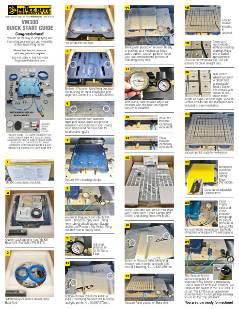
VM300Quick Start GuideCongratulations!!You are on the way to simplifying and improving your set-ups and versatilityof your machining center!Please feel free to contact us with any questions anytime 800-543-3580 • 603-539-4538***********************340 Rte. 16B • Ctr. Ossipee, NH 03814 • MADE IN THE USAVM300 component checklist.1Custom packaging for your VM300 Base Unit (Receiver) (PN 45175).2Additional accessories stored under Base Unit.3Secure with mounting clamps.7Assemble Regulator and attach with 6mm tubing to Supply Valve. Using 4mm tubing, attach Vacuum Gauge and/or Low Pressure Trip Switch fitting (located next to Supply Valve).8Adjust air pressure to 70-75 PSI or 5 bar.9With Blank Pallet installed adjust air pressure with regulator until highest vacuum is obtained.12Visual indicator identifying vacuum on.14VM300 Vacuum Pallet (PN 45150) ships with 1 pack each: Fixture Clamps (PN 50206) and Sliding Stops (PN 44200).15Vacuum pallet ready for workpiece.21Workpiece positioned against Sliding Stops(PN 44200).Close-up of adjustable Sliding Stops.22Vacuum Pallet placed on Base Unit.17Sealing Gasket installed inchannel.18Close up ofrecommended method of sealing chamber. Place end of Gasket approximately25% into perpendicular slot. Cut with scissors for clean straight end.19Top of VM300 Receiver.413Visual red indicator identifying vacuum off.Take care inadjusting Gasket to obtain best seal possible. Ensure Gasket is in contact with bottom of slot, check entirelength for gaps using flashlight. Vacuum Grease (PN 45094) and Installation Tool included to ease installation.20Recently added items include:Vacuum Gauge (12), Gasket Installation Tool, Set of Diamond Taper Pins, Vacuum Grease, 3 Carbide End Mills for custom vacuum plates,and a 4mm “Y” Connector which allows connections of the Vacuum Gauge and Low Pressure Trip Switch (LPTS) at the same time.Bottom of Receiver identifying precision drill bushing for quick installation and alignment. Centerline = 10.630"/270mm.5Machine platform with diamond taper pins allows quick and precise installation and removal of your tooling. Base Unit placed on these pins for location and rigidity.6Part Number 45175 andall accessories10Bottom of Blank Pallet (PN 45130 or 45135) identifying precision drill bushingsand grip points. CL = 10.630"/270mm.Blank pallet placed on receiver. Ready to machine as a mechanical fixture pallet, custom vacuum pallet or mount your vise eliminating the process of indicating every time.11Bottom of Vacuum Pallet identifying through hole in center and both prec-ision drill bushing. CL = 10.630"/270mm.16Open supply valve and check indicator and gauge for proper pressure. If using LPTSwe recommend mounting on backside of machine and adjust LPTS using gauge.23This Vacuum Systemcan be configured tostop machining functions immediately. Have a qualified technician connect Low Pressure Trip Switch to the FEED HOLD circuit. This LPTS has an adjustment screw between the two prongs allowing you to set the “trip” pressure.24T ripScrewY ou are now ready to machine!。
艾顿 Moeller 系列快速连接 DOL 启动器 198525 技术参数说明书

Eaton 198525Eaton Moeller® series Rapid Link - DOL starter, 6.6 A, Sensor input 2, 400/480 V AC, AS-Interface®, S-7.A.E. for 62 modules, HAN Q5General specificationsEaton Moeller® series Rapid Link DOL starter198525RAMO5-D204A32-5120S14015081964000120 mm 270 mm 220 mm 1.63 kgRoHS CE CCC UL 60947-4-2 UL approval IEC/EN 60947-4-2Assigned motor rating: for normal internally and externally ventilated 4 pole, three-phase asynchronous motors with 1500 rpm at 50 Hz or 1800 min at 60 HzProduct NameCatalog NumberModel CodeEANProduct Length/Depth Product Height Product Width Product Weight Certifications Catalog NotesIs the panel builder's responsibility. The specifications for the switchgear must be observed.3 kW6.6 A (at 150 % Overload)400 V AC, 3-phase480 V AC, 3-phase65000 A0 VMeets the product standard's requirements.Is the panel builder's responsibility. The specifications for the switchgear must be observed.Does not apply, since the entire switchgear needs to be evaluated.0 kW2.238 kWMeets the product standard's requirements.0 V-40 °CTwo sensor inputs through M12 sockets (max. 150 mA) for quick stop and interlocked manual operationElectronic motor protectionShort-circuit release Generation Change RASP4 to RASP5Generation change from RA-SP to RASP 4.0Configuration to Rockwell PLC for Rapid LinkConnecting drives to generator suppliesElectromagnetic compatibility (EMC)Generation change from RA-MO to RAMO 4.0Generation Change RA-SP to RASP5Generation change RAMO4 to RAMO5Rapid Link 5 - brochureDA-SW-USB Driver DX-COM-STICK3-KITDA-SW-drivesConnect USB Driver DX-COM-PCKITDA-SW-drivesConnectDA-SW-Driver DX-CBL-PC-3M0DA-SW-USB Driver PC Cable DX-CBL-PC-1M5DA-SW-drivesConnect - InstallationshilfeDA-SW-drivesConnect - installation helpMaterial handling applications - airports, warehouses and intra-logisticsProduct Range Catalog Drives EngineeringProduct Range Catalog Drives Engineering-ENDA-DC-00004525.pdfDA-DC-00004184.pdfDA-DC-00004523.pdfDA-DC-00003964.pdfeaton-bus-adapter-rapidlink-speed-controller-dimensions-002.eps eaton-bus-adapter-rapidlink-speed-controller-dimensions-003.eps eaton-bus-adapter-rapidlink-reversing-starter-dimensions.epseaton-bus-adapter-rapidlink-reversing-starter-dimensions-002.eps ETN.RAMO5-D204A32-5120S1.edzIL034084ZU10.11 Short-circuit ratingRated operational power at AC-3, 380/400 V, 50 HzInput currentRated operational voltageRated conditional short-circuit current, type 1, 480 Y/277 V Rated control supply voltage (Us) at AC, 50 Hz - min10.4 Clearances and creepage distances10.12 Electromagnetic compatibility10.2.5 LiftingRated power at 575 V, 60 Hz, 3-phaseRated power at 460 V, 60 Hz, 3-phase10.2.3.1 Verification of thermal stability of enclosures Rated control supply voltage (Us) at DC - minAmbient storage temperature - minFitted with:Application notes BrochuresCatalogs Certification reports DrawingseCAD model Installation instructionsKey switch position OFF/RESETThermo-clickKey switch position HANDThermistor monitoring PTCKey switch position AUTOAC-53a0 VAC voltagePhase-earthed AC supply systems are not permitted.Center-point earthed star network (TN-S network)Is the panel builder's responsibility.Class 10 A10 kA400/480 V AC -15 % / +10 %, Actuator for external motor brake 55 °C0 kW< 95 %, no condensationIn accordance with IEC/EN 50178Parameterization: KeypadDiagnostics and reset on device and via AS-Interface Parameterization: drivesConnectParameterization: FieldbusParameterization: drivesConnect mobile (App)10,000,000 Operations (at AC-3)Rapid Link 5MN034004EN MN040003_ENramo5_v1.dwg ramo5_v1.stpOverload cycleNumber of pilot lightsRated control supply voltage (Us) at AC, 50 Hz - max System configuration type10.8 Connections for external conductorsCoordination class (IEC 60947-4-3)Rated conditional short-circuit current, type 1, 600 Y/347 V Rated conditional short-circuit current (Iq)Braking voltageAmbient operating temperature - maxRated operational power at AC-3, 220/230 V, 50 Hz Climatic proofingFeaturesLifespan, electrical Installation videos Manuals and user guides mCAD modelNumber of command positions1Electrical connection type of main circuitPlug-in connectionElectrical connection type for auxiliary- and control-current circuit Plug-in connectionRated control supply voltage (Us) at DC - max0 V10.9.3 Impulse withstand voltageIs the panel builder's responsibility.Braking current≤ 0.6 A (max. 6 A for 120 ms), Actuator for external motor brakeAmbient operating temperature - min-10 °C10.6 Incorporation of switching devices and componentsDoes not apply, since the entire switchgear needs to be evaluated.Current limitation0.3 - 6.6 A, motor, main circuitAdjustable, motor, main circuitCable length10 m, Radio interference level, maximum motor cable length10.5 Protection against electric shockDoes not apply, since the entire switchgear needs to be evaluated.Mounting positionVerticalMains switch-on frequencyMaximum of one time every 60 secondsClassCLASS 10 A10.13 Mechanical functionThe device meets the requirements, provided the information in the instruction leaflet (IL) is observed.10.2.6 Mechanical impactDoes not apply, since the entire switchgear needs to be evaluated.10.9.4 Testing of enclosures made of insulating materialIs the panel builder's responsibility.10.3 Degree of protection of assembliesDoes not apply, since the entire switchgear needs to be evaluated.Electromagnetic compatibilityClass AVoltage typeDCProduct categoryMotor starterOverload release current setting - min0.3 ARated control voltage (Uc)24 V DC (-15 %/+20 %, external via AS-Interface® plug)400/480 V AC (external brake 50/60 Hz)Rated operational current (Ie)6.6 AAssigned motor power at 460/480 V, 60 Hz, 3-phase3 HPRated frequency - min47 HzNumber of auxiliary contacts (normally closed contacts)Rated conditional short-circuit current (Iq), type 2, 380 V, 400 V, 415 V0 APower consumption8 W10.2.3.2 Verification of resistance of insulating materials to normal heatMeets the product standard's requirements.10.2.3.3 Resist. of insul. mat. to abnormal heat/fire by internal elect. effectsMeets the product standard's requirements.On-delay20 - 35 msLifespan, mechanical10,000,000 Operations (at AC-3)Rated operational current (Ie) at 150% overload6.6 AProtocolAS-Interface profile cable: S-7.4 for 62 modulesASIOverload release current setting - max6.6 A10.9.2 Power-frequency electric strengthIs the panel builder's responsibility.Overvoltage categoryIIIDegree of protectionIP65NEMA 12Rated frequency - max63 HzVibrationResistance: According to IEC/EN 60068-2-6Resistance: 10 - 150 Hz, Oscillation frequency Resistance: 6 Hz, Amplitude 0.15 mmResistance: 57 Hz, Amplitude transition frequency on accelerationRated operational power at 380/400 V, 50 Hz - max3 kWAmbient storage temperature - max70 °CShort-circuit protection (external output circuits)Type 1 coordination via the power bus' feeder unit, Main circuitRated control supply voltage (Us) at AC, 60 Hz - min0 V10.7 Internal electrical circuits and connectionsIs the panel builder's responsibility.Rated impulse withstand voltage (Uimp)4000 VConnectionConnections pluggable in power sectionOff-delay20 - 35 ms10.10 Temperature riseThe panel builder is responsible for the temperature rise calculation. Eaton will provide heat dissipation data for the devices.FunctionsExternal reset possibleFor actuation of motors with mechanical brakeTemperature compensated overload protectionOutput frequency50/60 HzMains voltage tolerance380 - 480 V (-15 %/+10 %, at 50/60 Hz)Rated conditional short-circuit current (Iq), type 2, 230 V0 AInterfacesSpecification: S-7.A.E. (AS-Interface®)Max. total power consumption from AS-Interface® power supply unit (30 V): 190 mANumber of slave addresses: 62 (AS-Interface®)TypeDOL starter10.2.2 Corrosion resistanceMeets the product standard's requirements.Supply frequency50/60 Hz, fLN, Main circuit10.2.4 Resistance to ultra-violet (UV) radiationMeets the product standard's requirements.10.2.7 InscriptionsMeets the product standard's requirements.Rated control supply voltage (Us) at AC, 60 Hz - max0 VRated operational current (Ie) at AC-3, 380 V, 400 V, 415 V6.6 ARated operational power at 380/400 V, 50 Hz - min0.09 kWModelDirect starterNumber of auxiliary contacts (normally open contacts)Eaton Corporation plc Eaton House30 Pembroke Road Dublin 4, Ireland © 2023 Eaton. All Rights Reserved. Eaton is a registered trademark.All other trademarks areproperty of their respectiveowners./socialmedia15 g, Mechanical, According to IEC/EN 60068-2-27, 11 ms, Half-sinusoidal shock 11 ms, 1000 shocks per shaft Above 1000 m with 1 % performance reduction per 100 m Max. 2000 m Max. 1000 mShock resistanceAltitude。
Siemens S7-300 CPU312C 产品数据手册说明书

24 V No
6AG1312-5BF04-2AY0 Page 1/12
08/01/2014
subject to modifications © Copyright Siemens AG 2014
Input current Current consumption (rated value) Current consumption (in no-load operation), typ. Inrush current, typ. I²t Digital outputs from load voltage L+, max.
16 4
256
Yes 0 255 Z 0 to Z 7
0 999
Yes SFB Unlimited (limited only by RAM capacity)
256
Yes 0 255 No retentivity
08/01/2014
subject to modifications © Copyright Siemens AG 2014
STEP 7 V5.5 + SP1 or higher or STEP 7 V5.3 + SP2 or higher with HSP 203
Yes 19.2 V 28.8 V Miniature circuit breaker, type C; min. 2 A; miniature circuit breaker type B, min. 4 A
CPU processing times for bit operations, typ. for word operations, typ. for fixed point arithmetic, typ. for floating point arithmetic, typ.
米欧电子M-Series拆分空调系统产品说明书

Applicable Outdoor Models: SUZ-KA*NA2, SUZ-KA*NAR1, MUZ-JP*, MUFZ-KJ*, MUZ-GL*, MUY-GL*, MXZ-2~8C*, MUZ-FH*, MUZ-HE*, MUZ-D*, MUY-D*Applicable Indoor Models: MSZ-JP*, MSZ-EF*, MSZ-GL*, MSY-GL*, MSZ-FH*, MSZ-HE*, SEZ-KD*NA4, SEZ-KD*NA4R1, MFZ-KJ*, SLZ-KA*NAR1, SLZ-KF*, SVZ-KP*, MVZ-A*, MLZ0KP*LIMITED WARRANTY STATEMENTMitsubishi Electric M-Series Split Air-conditioner and Heat-pump SystemsSubject to the terms and conditions of this Limited Warranty Statement (the “Limited Warranty”), MITSUBISHI ELECTRIC TRANE HVAC US LLC (“METUS”) warrants to the original purchaser of this M-Series System (as used herein, “System” shall mean M-Series outdoor and indoor components connected via refrigerant piping and electrical wiring) purchased on or after May 1, 2019 from a licensed HVAC contractor and installed by such contractor in the continental United States, Alaska and Hawaii, that:A. The parts are warranted for a period of five (5) years to the original owner of the System. If any parts shouldprove defective due to improper workmanship and/or material for a period of five (5) years from the date of installation, METUS will replace any defective part without charge for the part. Replacement parts are warranted for the remainder of the original 5-year warranty period. Parts used for replacement may be of like kind and quality and may be new or remanufactured. Defective parts must be made available to METUS in exchange for the replacement parts and become the property of METUS.B. The compressor is warranted for a period of seven (7) years to the original owner of this System. If thecompressor should prove defective due to improper workmanship and/or material for a period of seven (7) years from the date of installation, METUS will replace the defective compressor without charge for the compressor. Replacement compressors are warranted for the remainder of the original 7-year warranty period. Compressors used for replacement may be of like kind and quality and may be new or remanufactured. Defective compressors must be made available to METUS in exchange for the replacement compressor and become the property of METUS.C. Notwithstanding the foregoing, if the System is installed in a residential single-family home and registeredwithin 90 days from installation, the parts and compressor will be warranted for a period of 10 years, to the original owner, so long as the original owner resides in the home. Specifically, if any parts and/or the compressor should prove defective due to improper workmanship and/or material for a period of ten (10) years from the date of installation, METUS will replace any defective parts or compressor without charge for the part or compressor. The replacement parts and/or compressor are warranted for the remainder of the original 10-year warranty period. Parts and/or compressors used for replacement may be of like kind and quality and may be new or remanufactured. Defective parts and/or compressors must be made available to METUS in exchange for the replacement parts and become the property of METUS.D. Notwithstanding the foregoing, if the System is installed in a residential single-family home by a DIAMONDCONTRACTOR and registered within 90 days from installation, the parts and compressor will be warranted fora period of 12 years, to the original owner, so long as the original owner resides in the home. Specifically, if anyparts and/or the compressor should prove defective due to improper workmanship and/or material for a period of twelve(12) years from the date of installation, METUS will replace any defective parts or compressor without charge for thepart or compressor. The replacement parts and/or compressor are warranted for the remainder of the original 12-year warranty period. Parts and/or compressors used for replacement may be of like kind and quality and may be new or remanufactured. Defective parts and/or compressors must be made available to METUS in exchange for the replacement parts and become the property of METUS.E. NO LABOR. These limited warranties do NOT include labor or any other costs incurred for service, maintenance,repair, removing, replacing, installing, complying with local building and electric codes, shipping or handling, or replacement of the System, compressors or any other parts. For items that are designed to be maintained or replaced by the original owner, the original owner is solely responsible for all labor and other costs of maintaining, installing, replacing, disconnecting or dismantling the System and parts (such as filters or belts) in connection with owner-required maintenance. Air filter cleaning and/or replacement for each applicable indoor unit are owner-required maintenance,and labor for this procedure is not covered under warranty. Please consult the applicable technical documentation for air filter cleaning and other maintenance procedures.F. PROPER INSTALLATION. This Limited Warranty applies only to Systems that are installed by contractors who arelicensed for HVAC installation under applicable local and state law, and who install the Systems in accordance with (i) all applicable building codes and permits: (ii) METUS’s installation and operation instructions: and (iii) good trade practices.G. REGISTRATION. To receive certain benefits under this Limited Warranty, as set forth in more detail above, the productmust be registered within 90 days of installation. To register, the original owner may complete and return the postage-paid registration card by U.S. mail or may register the product online at . Diamond Contractors may submit product registration information online via the extranet portal. Residents of California or Quebec need not register the product to receive warranty benefits, but are encouraged to do so.BEFORE REQUESTING SERVICE, please review the applicable technical documentation to insure proper installation and correct customer control adjustment for the System. If the problem persists, please arrange for warranty service.1) TO OBTAIN WARRANTY SERVICE:a. Contact the licensed contractor who installed the System or the nearest licensed contractor, dealer, or distributor(whose name and address may be obtained on our website at of any defect within the applicable warranty time period.b. Proof of the installation date by a licensed contractor is required when requesting warranty service. Present the salesreceipt, building permit or other document which establishes proof and date of installation. In the absence of acceptable proof, this Limited Warranty shall be deemed to begin one hundred twenty (120) days after the date of manufacture stamped on the System.c. This Limited Warranty applies only to Systems purchased on or after May 1, 2019, only while the System remains atthe site of the original installation, and only to locations within the continental United States, Alaska and Hawaii.2) THIS LIMITED WARRANTY DOES NOT COVER: property damages, malfunction or failure of the System, or personalinjury caused by or resulting from: (a) accident, abuse, negligence or misuse; (b) operating the System in a corrosive or wet environment, including those containing chlorine, fluorine or any other hazardous or harmful chemicals or environmental factors, including sea- or salt-water; (c) installation, alteration, repair or service by anyone other than a licensed contractor or other than pursuant to the manufacturer’s instructions; (d) improper matching of System components; (e) improper sizing of the System; (f) improper or deferred maintenance contrary to the manufacturer’s instructions; (g) physical abuse to or misuse of the System (including failure to perform any maintenance as described in the Operation manual such as air filter cleaning, or any System damaged by excessive physical or electrical stress; (h) Systems that have had a serial number or any part thereof altered, defaced or removed; (i) System used in any manner contrary to the Operation Manual; (j) freight damage; or (k) events of force majeure or damage caused by other external factors such as lightning, power surges, fluctuations in or interruptions of electrical power, rodents, vermin, insects, or other animal- or pest-related issues.3) THIS LIMITED WARRANTY ALSO EXCLUDES: (a) SERVICE CALLS WHERE NO DEFECT IN THE SYSTEM COVEREDUNDER THIS WARRANTY IS FOUND: (b) System installation or set-ups; (c) Adjustments of user controls; (d) Systems purchased or installed outside the continental United States, Alaska and Hawaii; or (e) Systems purchased or installed prior to May 1, 2019. Consult the operating instructions for information regarding user controls.4) This Limited Warranty shall not be enlarged, extended or affected by, and no obligation or liability shall arise or grow out of,METUS providing, directly or indirectly, any technical advice, information and/or service to original owner in connection with the System.5) EXCEPT AS OTHERWISE PROVIDED IN THIS LIMITED WARRANTY, METUS MAKES NO OTHER WARRANTIES OFANY KIND WHATSOEVER REGARDING THE SYSTEM. METUS DISCLAIMS AND EXCLUDES ALL WARRANTIES NOT EXPRESSLY PROVIDED HEREIN AND ALL REMEDIES WHICH, BUT FOR THIS PROVISION, MIGHT ARISE BY IMPLICATION OR OPERATION OF LAW, INCLUDING, WITHOUT LIMITATION, THE IMPLIED WARRANTIES OFMERCHANTABILITY, NON-INFRINGEMENT OF THIRD PARTY RIGHTS, AND OF FITNESS FOR ANY PARTICULAR PURPOSE. NO ONE IS AUTHORIZED TO CHANGE THIS LIMITED WARRANTY IN ANY RESPECT OR TO CREATE ANY OTHER OBLIGATION OR LIABILITY FOR METUS IN CONNECTION WITH THE SYSTEM. METUS DISCLAIMS ALL LIABILITY FOR THE ACTS, OMISSIONS AND CONDUCT OF ALL THIRD PARTIES (INCLUDING, WITHOUT LIMITATION, THE INSTALLING CONTRACTOR) IN CONNECTION WITH OR RELATED TO THE SYSTEM.6) UNDER NO CIRCUMSTANCES SHALL METUS BE LIABLE FOR ANY INDIRECT, INCIDENTAL, SPECIAL, PUNITIVEOR CONSEQUENTIAL DAMAGES INCLUDING, WITHOUT LIMITATION, INFRINGEMENT OF THIRD PARTY RIGHTS, LOST GOODWILL, LOST REVENUES OR PROFITS, WORK STOPPAGE, SYSTEM FAILURE, IMPAIRMENT OF OTHER GOODS, COSTS OF REMOVAL AND REINSTALLATION OF THE SYSTEM, LOSS OF USE, INJURY TO PERSONS OR PROPERTY ARISING OUT OR RELATED TO THE SYSTEM WHETHER BASED ON BREACH OF WARRANTY, BREACH OF CONTRACT, TORT OR OTHERWISE, EVEN IF METUS HAS BEEN ADVISED OF THE POSSIBILITY OF SUCH DAMAGE. IN NO EVENT SHALL METUS’S LIABILITY EXCEED THE ACTUAL PURCHASE PRICE OF THE SYSTEM WITH RESPECT TO WHICH ANY CLAIM IS MADE.7) SOME STATES DO NOT ALLOW LIMITATIONS ON WARRANTIES OR EXCLUSIONS OR LIMITATION OFDAMAGES, SO THE ABOVE LIMITATIONS OR EXCLUSIONS MAY NOT APPLY.8) DISPUTE RESOLUTION.For any dispute with METUS, you agree to first contact us by phone (800-433-4822) or e-mail(*********************.com)orU.S.MailatMitsubishiElectricTRANEHVACUSLLCATTN:CustomerCare,1340 Satellite Blvd., Suwanee, GA 30024, and attempt to resolve the dispute with us informally by providing your name, address, and contact information and describing the nature of the dispute. In the unlikely event that METUS has not been able to resolve a dispute with you within 60 days of your original informal claim (or sooner if, in METUS’s opinion, a dispute is not likely to be resolved within 60 days), we each agree to resolve any claim, dispute, or controversy arising out of or in connection with or relating to this Limited Warranty, or the breach or alleged breach thereof (collectively, “Claims”), by binding arbitration before an arbitrator from Judicial Mediation and Arbitration Services (“JAMS”) located in Gwinnett County, Georgia. JAMS may be contacted at and will require you to pay an initial filing fee set by JAMS (unless you successfully apply for a waiver of this fee from JAMS). All other JAMS costs associated with the arbitration will be borne by METUS. The arbitration will be conducted in Gwinnett County, Georgia, unless you request an in-person hearing where you live, or if you and METUS agree otherwise. If the arbitrator decides in your favor, the award may include your costs of arbitration, your reasonable attorneys' fees and your reasonable costs for any expert and other witnesses, and any judgment on the award rendered by the arbitrator may be entered in any court of competent jurisdiction. If the arbitrator makes an award in your favor greater than METUS's last written offer, METUS will pay you the greater of the award or $500, plus your reasonable attorney's fees, if any, and reimburse any reasonable expenses (including reasonable expert witness fees and costs) that are reasonably accrued for investigating, preparing, and pursuing your claim in arbitration, as determined by the arbitrator or as agreed to by you and METUS. Any judgment on the award rendered by the arbitrator may be entered in any court of competent jurisdiction. You may sue under state law in a small claims court of competent jurisdiction without first engaging in arbitration, but you must engage in arbitration before suing under the Federal Magnuson-Moss Act.9) All claims must be brought in the parties’ individual capacity, and not as a plaintiff or class member in any purported classor representative proceeding. This waiver applies to class arbitration unless such arbitration is necessary to effectuate the enforcement of the court class action waiver or in the event that class arbitration is expressly agreed to by METUS. You agree that you and METUS are each waiving the right to a trial by jury or to participate in a class action.10) You may opt-out of the foregoing arbitration and class action/jury trial waiver provision of this Limited Warranty by notifyingMETUS in writing within 30 days of purchase. Such written notification must be sent to Mitsubishi Electric TRANE HVAC US LLC ATTN: Legal, 5900-A Katella Avenue, Cypress, CA 90630, and must include (1) your name, (2) your address, (3) your warranted product’s serial number, and (4) a clear statement indicating that you do not wish to resolve disputes through arbitration and demonstrating compliance with the 30-day time limit to opt-out.11) If any clause herein is found to be illegal or unenforceable, that clause will be severed from this Limited Warrantyand the remainder of the Limited Warranty will be given full force and effect. As noted above, if a class action waiver of both court and arbitration class actions is found unenforceable, class arbitration will be expressly allowed under the Limited Warranty.12) Residents of California and Quebec do not need to register the product in order to get all of the rights and remediesof registered original owners under this warranty.13) This Limited Warranty gives the original owner specific legal rights and the original owner may also have otherrights that vary from state to state.14) This Limited Warranty is valid only in the continental United States, Alaska and Hawaii, and it is not transferable.。
广西电信EPON上行E8-C终端IPv6双栈和DS-lite功能测试方案

广西电信EPON上行E8-C终端IPv6双栈和DS-Lite功能测试方案广西区通信产业服务有限公司技术服务分公司2013年6月一、测试组网 (一)IPv6双栈测试组网图(二)DS-Lite 测试组网图IPv6 网络 IPv4 网络ME60 HG2001:0:1:1::2128.0.0.1 10.0.0.1 192.168.0.1 10.0.0.2 城域网二、设备信息设备型号:硬件版本:软件版本:Outer IPv6 SA : 2001:0:0:1::2Outer IPv6 DA : 2001:0:0:1::1 Inner IPv4 SA : 192.168.1.12Inner IPv4 DA : 129.0.0.1IPv6 网络 192.168.1.122001:0:1:1::2 192.168.1.1 2001:0:0:1::2 2001:0:1:1::1 2001:0:0:1::1 128.0.0.1DS Lite CGND 4i VIPv4网络IPv6网络 4in6 tunnelDS Lite CPE三、测试内容(一)IPv6数据转发功能测试1、通过PPP方式建链测试(V4/V6单PPPoE SESSION方式)2、WAN侧SLAAC功能测试3、IPv6双栈功能测试(二)DNSv6功能测试(三)IPv6地址管理功能测试1、DHCPv6功能测试2、LAN侧 SLAAC功能测试3、DHCPv6-PD功能测试(四)IPv4/v6组网1、IPv4/v6双栈测试(五)DS-Lite功能测试1、本地配置PPPoE+SLAAC+DHCPv62、远程配置PPPoE+SLAAC+DHCPv6。
- 1、下载文档前请自行甄别文档内容的完整性,平台不提供额外的编辑、内容补充、找答案等附加服务。
- 2、"仅部分预览"的文档,不可在线预览部分如存在完整性等问题,可反馈申请退款(可完整预览的文档不适用该条件!)。
- 3、如文档侵犯您的权益,请联系客服反馈,我们会尽快为您处理(人工客服工作时间:9:00-18:30)。
Reading Assignment:
Howe and Sodini; Chapter 7, Sections 7.3, 7.4 & 7.5
6.012 Spring 2009
Lecture 18
1
1. BJT: Regions of Operation
VBE VBC + B +
VBE E
VCE
IB>0 VBE < 0 VBC > 0
Minority Carrier Profiles (not to scale):
emitter base collector
pnE
npB
pnC
pnCo npBo
x
pnEo -WE-XBE
-XBE 0
WB WB+XBC WB+XBC+WC
6.012 Spring 2009
Lecture 18
5
ReverseActive Region: VBE < 0, VBC > 0
• Collector injects electrons into base, emitter extracts (collects) electrons from base: VBC qAC n pBo Dn Vth IE = IS e ; IS = WB
B
[ ] Ie
VBC Vth
S
E
E
For today’s technology: VBC,on ≈ 0.6 V
6.012 Spring 2009 Lecture 18 13
Simplification of equivalent circuit model:
[ ]
• Base injects holes into collector, holes recombine at collector contact and buried layer:
IS e IB = βR
( )− 1 ;
VBC Vth
βR
VBC Vth
IS
=
qAC pnCo D p WC
6.012 Spring 2009
Lecture 18
8
Saturation Region: VBE > 0, VBC > 0
n-Emitter IE p-Base n-Collector IC
IB <0 IB >0 VBE > 0 VBC > 0
Minority Carrier profiles (not to scale):
• State-of-the-art IC BJT’s today: IS ≈ 0.1 - 1 fA • βF ≈ 50 - 300. • βF hard to control tightly: ⇒ circuit design techniques required to be insensitive to variations in βF.
6.012 Spring 2009
Lecture 18
10
Saturation - The Flux Picture
Both junctions are injecting and collecting. Electrons injected from emitter into base are collected by the collector as in Forward Active case. Electrons injected from collector into the base are collected by the emitter as in Reverse Active case. Holes injected into emitter recombine at ohmic contact as in Forward Active case. Holes injected into collector recombine with electrons in the n+ buried layer
C C
B
B VBE,on
[ ] Ie
VBE Vth
S
E
E
For today’s technology: VBE,on ≈ 0.7 V. IB depends on outside circuit. • Reverseactive region: VBE < 0, VBC > 0
C C
VBC,on B
VBC Vth
• Collector current:
IS [ ] [ ] I C = − I E − I B = − I Se − e −1
βR
• Typically, βR ≈ 0.1 - 5 << βF .
Dn IE WB N dC DnWC βR = = = D p N aB D pWB IB pnCo • WC n pBo •
VBC Vth
[ ]
− 1
VBE Vth
IE = − IS e
I [ ]− e[ ] [ ] − S e − 1 βF
• IC and IE can have either sign, depending on relative magnitudes of VBE and VBC and βF and βR.
Minority Carrier Profiles (not to scale):
emitter base collector
pnE
npB
pnC
pnCo npBo
x
pnEo -WE-XBE
-XBE 0
WB WB+XBC WB+XBC+WC
6.012 Spring 2009
Lecture 18
7
CutOff Region: VBE < 0, VBC < 0
Dn I WB N dE DnWE βF = C = = D IB N aB D pWB pnEo • p WE n pBo •
6.012 Spring 2009 Lecture 18 4
ReverseActive Region: VBE < 0, VBC > 0
n-Emitter IE>0 p-Base n-Collector IC<0
emitter base collectorpEnpBpnC
pnCo npBo
x
pnEo -WE-XBE
-XBE 0
WB WB+XBC WB+XBC+WC
6.012 Spring 2009
Lecture 18
9
Saturation Region: VBE > 0, VBC > 0
Saturation is superposition of forward active + reverse active:
[ ] [ ]
[ ]
[ ]
[ ]
[ ] [ ]
[ ]
Equivalent-circuit model representation (nonlinear hybridπ model) [particular rendition of Ebers-Moll C model in text]: IC VBC I S / βR B + + IB IR IF I S / βF VBE E IE βFIF - βRIR =IS[exp(qVBE/kT) - exp(qVBC/kT)]
Three parameters in this model: IS, βF, and βR.
6.012 Spring 2009 Lecture 18 12
Simplification of equivalent circuit model:
• Forwardactive region: VBE > 0, VBC < 0
– ⇒ takes time to get out of saturation
6.012 Spring 2009
Lecture 18
2
ForwardActive Region: VBE > 0, VBC <0
n-Emitter p-Base n-Collector IC>0
IE<0
IB>0 VBE > 0 VBC < 0
VBC cut-off reverse C
+
forward� active
saturation
• Forward active: device has high voltage gain and high β; • Reverse active: poor β; not useful; • Cutoff: negligible current: nearly an open circuit; • Saturation: device is flooded with minority carriers;
• Emitter injects electrons into base, collector extracts (collects) electrons from base:
[ ]; I C = I Se
VBE Vth
IS =
qAE npBo Dn WB
• Base injects holes into emitter, holes recombine at emitter contact:
• Base extracts holes from emitter: