RF cable verify
Agilent 8590 E-Series 蔚蓝无线分析仪用户手册说明书

1981Agilent 8590 E-SeriesPortable SpectrumAnalyzersSpectrum Analysis by Agilent,Tailored Solutions to Meet Your Needs2Optional capability:•Separate closely spaced signals and increase sensitivity with narrow resolution bandwidths.•Measure digital transmitter power, timing, frequency, and modulation with digitaldemodulators for any of the major cellular and cordless formats.• Analyze “bursted” signals with time-gated spectrum analysis.• Assure EMI precompliance with quasi-peak detector.• Test components for scalar parameters with built-in tracking generators.•With group delay and amplitude flatness capability, you can do link analysis on…- Microwave radios - Satellites - CablesPLUS...there are over 20 other performance options you can choose from!Note the modulation quality of a GSM900 signalTransmission and reflection results for scalar testOptional hardware configurations…add performance and capability.Agilent Technologies has designed a series of Spectrum Analyzers that can be configured to your specific measurement needs.With the internal cardcage, circuit-card options can be inserted into any of four internal card slots toincrease your measurement capabilities.And should your needs change,your analyzer can adapt since most options are retrofittable.Flexible spectrum analysis PLUS...3Downloadable measure-ment personalities…add powerful measurement routines.For each application, Agilent offers a unique software program (provided on ROM-based memory cards), designed specifically for the 8590 E-series. Downloaded into analyzer memory, each meas-urement personality provides measurement setups, routines,and results specific to your appli-cation, as well as a user interface with terminology directly related to that application!Choose from a wide selection of measurement personalities:•RF Wireless Communications •Cable TV•EMI Precompliance •Microwave Links •Noise Figure •Lightwave •Broadcast TV •Digital Radio •Scalar Analysis•Customized personalities we create specifically for you!Benefits include:• Ease of use with one-button measurements• Complex tests are performed simply and quickly • Improved accuracy and repeatability over manual measurements•Results are operator independent• Save coding time with remotely programmable subroutines• Decreased training timePLUS…when you add them all together, you save time and money!EMI measurement compared to regulatory limitsApplication software EQUALS ... tailored solutions for you!Internal option cardcageCustomize your analyzer now or in thefuture with our plug-in, circuit-card options.Measurement Power Tailored for Your Success…4Softkey menus Array Operate your analyzer more easilywith related softkey functions.Zoom window (onscreen)Focus in on critical data quicklyand easily.Sturdy designTough and resilient: wherever youhave to go, your analyzer will, too.Internal option cardcageCustomize your analyzer now orin the future with our plug-in,circuit-card options.Built-in measurementsand advanced functionsAllow you to perform complexmeasurements with one-buttonease.I/O and parallel printer portExecute remote programs overGPIB or RS-232 and print testresults using the parallel printerinterface.Wide frequency rangesChoose from 9 kHz to 1.8 GHz,2.9 GHz, 6.5 GHz, 12.8 GHz,22 GHz, or 26.5 GHz.Card readerStore data on 128 Kbyte memorycards... and download measure-ment personalities.5Features and options summary6Performance summarySpecification summarySpecification18591E 8594E 8595E 8596E 8593EFrequency accuracy2, 3, 4±210 Hz±210 Hz±210 Hz±1.2 kHz±1.2 kHz Resolution bandwidth30 Hz to 3 MHz 30 Hz to 3 MHz30 Hz to 3 MHz 30 Hz to 3 MHz30 Hz to 3 MHz range4(10 Hz Nominal)(10 Hz Nominal)(10 Hz Nominal)Average noise level(30 Hz-RBW)4–130 dBm–127 dBm–127 dBm–127 dBm–129 dBm Optimum dynamic range(2nd/3rd Order)477 dB/90 dB78 dB/88 dB77 dB/86 dB102 dB/80 dB103 dB/81 dB Relative frequencyresponse±1.0 dB±1.0 dB±1.5 dB±2.0 dB±2.0 dBCalibrated displayrange70 dB70 dB70 dB70 dB70 dBAmplitude range4–130 dBm–127 dBm–127 dBm–127 dBm–129 dBmto +30 dBm to +30 dBm to +30 dBm to +30 dBm to +30 dBmPhase noise(30 kHz Offset, 1 GHz)–105 dBc/Hz–105 dBc/Hz–105 dBc/Hz–105 dBc/Hz–105 dBc/Hz7• Adjacent channel power (ACP)• Occupied bandwidth power • Third-order intercept• Percent AM• Signal bandwidth• Channel powerZoom in on signals with zoom window split screen displayJust one button calculates T.O.I. distortion products!• Fast-Fourier-Transform (FFT)allows quick analysis of the AMcomponents on the signal ofinterest.• Time-gated spectrum analysisobtains spectral details ofburst-modulated signals.sorted by frequency or amplitude.• And moreMeasure –1 to –80 dB bandwidths on signals.Now you can immediately identify amplitudeand frequency of top 10 peaks ... automatically!Built-in one-button measurement routines …save time, setup and training!Built-in functions…reduce analysis and troubleshooting time!89Automation and remote control…provide faster measurements through programmability!Reliability, service, and worldwide support network…provide solutions that lower your cost of ownership!Here’s what programming can do for you:• Automate routine measurement tasks• Increase testing throughput • Reduce complex measurements and calculate results• Improve measurement quality, accuracy, and repeatabilityTwo types of programs can beused to control the 8590 E-series spectrum analyzers:1. Remote programs can bedeveloped for controlling your spectrum analyzer from your computer when connected to either the GPIB or RS-232 interface of the analyzer; or,2. Downloadable programs (DLPs)can be developed to locallycontrol your spectrum analyzer.These programs, downloaded into your analyzer’s internal memory, provide customized measurement routinesassignedto analyzer softkeys.You can program your analyzer to perform repetitive tasks — and that saves measurement time andmoney! Use over 200 fully documented programming commands to develop programs that specificallymeet your needs, or, call upon expert application engineers — available worldwide — to write programs for you.All 8590 E-series spectrum analyzers…• Are manufactured in an ISO 9001 registered facility to exacting standards…and come with optional calibration certificates traceable to national standards; and• Comply with U.S. military MIL-T-28800 class 5 environmental standards ... and that meansreliable, accurate performance in portable applications; and • Contain built-in self-tests and calibration routines to ensure measurement integrity; and • Are delivered with the most thorough user, calibration and service documentation in the industry and with complete calibration and serviceavailable at 27 Agilent locations worldwide.Agilent’s technical professionals…• Are a phone call away to provide technical application assistance;• Are available to provide local user training; and,•Are available to provide factory service training to support your internal calibration and service needs.10Research and developmentShorten your development time by equipping your engineering team with the analysis tools they need to optimize their designs.• Speed-up design trouble-shooting with built-in,one-button measurementroutines. For example,Third-Order-Intercept,Adjacent Channel Poweror one of Agilent’s measure-ment personalities.• Use the 8590-series analyzerswith EEsof’s MDS Modelingand Simulation Software toverify breadboard performance,as compared to circuitsimulations.•Minimize costs associated with buying additional instruments and adding bench space by leveraging the 8590 E-series scalar and noise figure capabilities.ManufacturingEnhance your production line throughput with analyzersdesigned for measurement speed in automated test systems and for ease-of-use in individually operated test stations.• Reduce test costs and increase throughput, accuracy, andrepeatability with built-in routines.Perform “go/no-go” testing with features like limit lines andeasily interpreted PASS/FAILmessages.•Automate your testing toimprove throughput andaccuracy by programming youranalyzer to perform repetitivemeasurement tasks.•Execute programs from theanalyzer’s memory or your PC.• Save money on futureequipment purchases whenproduction line requirementschange by retrofitting newcapabilities into your8590 E-series.Field service, installation and signal surveillanceTake the power and flexibility of the 8590 E-series with you wherever you need on-site analysis.• Carry less equipment with you into the field by equipping your analyzer with optional, multi-performance capabilities, such as group delay or on-screen TV picture.• Store test results in the field on compact, rugged, solid state memory cards with automatic time/date stamps.• Record screen data with VCR for long term signal monitoring;limit lines provide signal activity alerts.• Field accessories include an external battery pack CRT sun shield, protective front cover,operating/carrying case, nylon backpack, and transit case.Application specific literatureLiterature Number 8590 C/E/L and EM Series Configuration Guide 5963-6858E 8590L and 8592L Product Overview 5962-7275E 8590 E-series Technical Specifications5963-6909EManufacturing, field and moreGeneral purpose spectrum analysisThis easy-to-use tool provides a broad range of testing capability across a wide variety of applica-tions. You can display relationships between power, frequency, and time with over 200 built-in measurement functions!Note:For lowest cost, general purpose RF/MW spectrum analysis, see the 8590 L-series. Contact your Agilent representative for more information.Customize your transmitter testingFor the design, manufacturing, installation, or service of digital RF wireless communications equipment, the 8590 E-series spectrum ana-lyzer with measurement personality is the tool you need.Quick, easy, one-buttontransmitter measurements•Customized transmitter testsbased on industry standardsfor GSM, DCS1800, NADC-TDMA, CDMA, PDC, DECT,CT2-CAI, and PHS•Fast, easy, one-button trans-mitter measurement person-Additional features make yourmeasurement easier•Automatic tuning by channelnumber• Pass/Fail messages• Continuous measurement modefor real-time equipmentadjustments and troubleshooting• Results displayed in numericIQ diagram of a NADC-TDMA signalChannel power of a CDMA signalMeasurement Personality Literature Number5966-3803E5962-6217E5963-9971E5091-7761E5963-9969E5964-0110EDigital RF wireless communicationsThe measurementsyou need in one convenient packageWhen it comes to installing and maintaining a microwave radio system, you can select the test solution that exactly meets your needs. Choose from personalities, options and system configurations created specifically for those who install and maintain microwave radios of all types—from routine maintenance of low capacity links to installation and commissioning of high capacity systems.Digital radio measurements•For low-capacity systemmaintenance, the 85713ADigital Radio MeasurementsPersonality adds mask com-parison, mean-power-level,frequency response and transientmeasurement capabilities to thestandard Spectrum Analyzer.The personality includesstandard FCC, UK and FRGagency masks, as well as theability to create custom masks.•For higher capacity systems,group delay and amplitudeflatness measurements may berequired. The 11770A LinkMeasurements Personality, inconjunction with Option 111in the Spectrum Analyzer, usesthe analyzer and its trackinggenerator as receiver andtransmitter respectively.Two independent analyzerscan be used for end-to-endand frequency translationmeasurements over the entirefrequency range of the generatoroutput and analyzer input.• The 11758V Digital Radio Testsystem provides comprehensivemeasurement capability forinstallation and maintenanceof high capacity systems. Thesystem is based on a specially-configured 8593E SpectrumAnalyzer and the 11758BMultipath Fading Simulator.Available options include:-group delay- a microwave source forantenna return loss measure-ments- a fully configured system formicrowave satellite systemgroup delay measurementsbased on a synthesizedsweeper.Factory integrated specialconfigurations are available.Amplitude and group delay response foradjusting transmission networksLiterature NumberTools for Digital Microwave Radio Installation & Maintenance (AN 355-1)5962-9920E5091-4651E11770A Link Measurements Personality Data Sheet5091-4652E Digital radioDifferential gain and phase video measurements made to world wide standards.Your portable, single box tester for both RF and video measurementsSave time in cable TV manufacturing and maintenance with fast one-button measurement routines. Agilent Technologies offers two solu-tions for the cable TV industry; the 8590 E-series spectrum analyzer with the 85721B cable TV measurement personality for manufacturers,or the CaLan 8591C cable TV analyzer for cable TV operators. TheCaLan 8591C includes many 8590 E-series analyzer options specifically for cable TV testing!Featuresand options include:•Dedicated Cable TV measure-ments which provide one-button,non-interfering RF and video tests.•Automated compliance testing to FCC regulations and world-wide standards.• System tests for installation, maintenance, troubleshooting and performance monitoring.•Five frequency ranges, 1.8 GHz to 22/26.5 GHz (8590 E-series).• 75-ohm input that matches analyzer to trunk cable or other 75-ohm environments.• Flexible hardware and software architecture for easy upgrading. • 75-ohm pre-amp for low-level carrier-to-noise measurements.• Dual interfaces; a parallel printer port with either an GPIB or RS-232 port.• Television picture capability to verify subscriber complaintsWith your analyzer, you can determine…RF measurements:• Automatic tuning to cable TV and broadcast carriers.• Visual and aural carrier levelsand frequencies• System channel survey • Depth of modulation • Crossmodulation• Aural and FM broadcast carrier deviation • Carrier-to-noise ratio• In-channel frequency response • Hum and low frequency disturbances• System frequency response • Distortion (CSO/CTB)Video measurements:• Differential gain • Differential phase• Chrominance-to-luminance delay inequalityAdd the Agilent CaLan 85921B FCC report generator for moving test data from your analyzer to your PC and providing FCC proof-of-performance reports!Cable TVThe design cycleThere’s no better time than early in the design cycle to solve EMC problems—problems that could prove very costly to correct, even to the point of delaying a new product’s introduction — prob-lems you can identify and analyze at the push of a button with 8590 E-series spectrum analyzers.• Use your 8590 E-series analyzer with the EMC measurement personality (85712D), antennas and accessories to search for radiated emissions.•Measure conducted emissions with the LISN and accessories. • Using the close-field probe set (11945A Option E51), pinpoint emissions, make design changes and compare the results.Selected featuresand options include:• Automated, one-button EMCprecompliance measurements.• Fast setup of all EMC measure-ment system parameters from arange of setup libraries.• Measure the quasi-peak, averageand peak levels of up to 20 signalsautomatically.• Enhanced measurementaccuracy with built-in transduceramplitude corrections.• Built-in tracking generator forshielding effectiveness andimmunity testing.• System diagnostic tools to quicklyisolate, classify and record EMCdesign problem spots.• A complete line of EMCtransducers and accessories toperform EMI measurements tomeet your needs. Avoid costly EMC compliance delaysThe 8590 E-series spectrum analyzer and 85712D EMC measurementpersonality, options and accessories give you EMC precompliance anddiagnostic capabilities. For dedicated EMI users, Agilent recommendsthe 8590EM series EMC analyzers.EMC precomplianceApplication specific literature Literature Number8590EM Series EMC Analyzers andPrecompliance Systems5964-6091EEMC Accessories Catalog5966-1188Eyou’re not forced to purchase multiple instruments —now you can com-bine the functions of a spectrum analyzer, noise figure meter, and scalaroptional 1.8/2.9 GHz built-in tracking…add the 5630A scalar test set for:• Simultaneous transmission/reflection• Built-in RF bridges• Ease of set-up and useMeasure swept noise figure and gain ofan amplifierOrdering informationSpectrum analyzers8591E RF Spectrum Analyzer (9 kHz to 1.8 GHz)8594E RF Spectrum Analyzer (9 kHz to 2.9 GHz)8595E RF Spectrum Analyzer (9 kHz to 6.5 GHz)8596E MW Spectrum Analyzer (9 kHz to 12.8 GHz)8593E MW Spectrum Analyzer (9 kHz to 22/26.5 GHz)Options, measurement personalities, and accessoriesFor complete ordering and compatibility information on available options, retrofit kits, and measurement personalities,please see the 8590 C/E/L and EM Series Configuration Guide, Literature Number 5963-6858E.Literature reference indexLiterature General purpose information Number 8590L and 8592L Product Overview5962-7275E 8590 E-Series Technical Specifications5963-6909E 8590 C/E/L and EM Series Configuration Guide5963-6858EProduct feature briefsAnalog+ Display5091-4054E Transmitter Power Measurements (ACP, OBW)5091-4055E Zoom Window5091-4051E Measuring AM with FFT5091-4049E Time-Gated Spectrum Analysis5091-4053E Editing Keyboard5091-4048E Marker and Peaks Table5091-4050E Third Order Intermodulation, N dB Bandwidth and Percent AM 5091-4052E Product notesTime-Gated Spectrum Analysis (8590-2)5952-3685 Analog+ Display 5091-2364E Maximizing Accuracy in Noise Figure Measurements (85719A-1)5091-4801E Application notesSpectrum Analysis Basics (150)5952-0292 Amplitude and Frequency Modulation (150-1)5954-9130Agilent Technologies’ Test and Measurement Support, Services,and AssistanceAgilent Technologies aims to maximize the value you receive, while minimizing your risk and problems. We strive to ensure that you get the test and measurement capabilities you paid for and obtain the support you need. Our extensive support resources and services can help you choose the right Agilent products for your applications and apply them successfully. Every instrument and system we sell has a global warranty. Support is available for at least five years beyond the production life of the product. Two concepts underlie Agilent’s overall support policy: “Our Promise” and “Your Advantage.”Our PromiseOur Promise means your Agilent test and measurement equipment will meet its advertised performance and functionality. When you are choosing new equipment, we will help you with product information, including realistic performance specifica-tions and practical recommendations from experienced test engineers. When you use Agilent equipment, we can verify that it works properly, help with product operation, and provide basic measurement assistance for the use of specified capabilities, at no extra cost upon request. Many self-help tools are available.Your AdvantageYour Advantage means that Agilent offers a wide range of additional expert test and measurement services, which you can purchase according to your unique techni-cal and business needs. Solve problems efficiently and gain a competitive edge by contracting with us for calibration, extra-cost upgrades, out-of-warranty repairs, and on-site education and training, as well as design, system integration, project management, and other professional engineering services. Experienced Agilent engineers and techni-cians worldwide can help you maximize your productivity, optimize the return on investment of your Agilent instruments and systems, and obtain dependable measure-ment accuracy for the life of those products. For more assistance with your testand measurement needs go to/find/assist Copyright © 2000 Agilent Technologies Printed in USA 7/005963-6908E。
Intellian i3 i4 i4P 产品说明书

CONTENTSINTRODUCTION (1)I NTRODUCTION TO I NTELLIAN I3/I4/I4P (1)F EATURES OF I NTELLIAN I3/I4/I4P (2)B ASIC S YSTEM C ONFIGURATION OF I NTELLIAN I3/I4/I4P (3)INSTALLATION (4)S YSTEM C OMPONENTS (4)T OOLS R EQUIRED FOR I NSTALLATION (7)P LANNING THE INSTALLATION (8)S ELECTION OF I NSTALLATION S ITE (8)I NSTALLATION AND M OUNTING OF ANTENNA (10)I NSTALLING THE ACU (15)C ONNECTING THE S YSTEM C ABLES (17)C ONNECTING THE SYSTEM TO A GPS (20)T ARGET S ATELLITE S ETTING (21)A DJUSTING THE LNB S KEW A NGLE (L INEAR POLARIZATION ONLY) (22)OPERATION INSTRUCTION (24)I NTRODUCTION (24)OPERATION USING THE ACU (25)ACU S OFT K EYS (25)N ORMAL M ODE (25)S ET U P M ODE (30)OPERATION USING PC CONTROLLER PROGRAM (52)I NTRODUCTION (52)P ROGRAM I NITIALING AND S ERIAL P ORT S ETUP (53)M AIN M ENU –U SING D EFAULT D UAL-SAT M ODE (54)S ET S ATELLITE I NFORMATION (55)M AIN M ENU-U SING A DV ANCED T RI-SAT M ODE (56)S ET S ATELLITE I NFORMATION (57)C ONTROLLER MENU (60)TROUBLESHOOTING (65)PREPARATION FOR TRANSPORTATION (67)WARRANTY (68)APPENDIX : TECHNICAL SPECIFICATION (69)I NTELLIAN I4/I4P (69)I NTELLIAN I3 (70)INTRODUCTIONIntroduction to Intellian i3/i4/i4PIntellian i3/i4/i4P is a digital satellite antenna system designed specificallyfor all types of vessels (Anchored or transit) to automatically identify, trackand capture satellite signals from the Digital Video Broadcasting (DVB: the international standard for digital TV transmissions) compatible satellites.Specifically, Intellian i3/i4/i4P has Wide Range Search (WRS) algorithm, which minimizes the search time during initialization, and Dynamic Beam Tilting (DBT) technology, which dynamically shapes the antenna beam to utilize stabilization. Once the satellite is acquired, the antenna DBT continuously measures the heading, pitch, and roll of the vessel by obtaining the satellite signal level around the antenna point, and transmitscommands to the antenna motors to keep the antenna pointed at the satellite at all times. This active stabilization is enhanced by a conical scan tracking function to detect and lock onto the strongest signal, resulting in the clearest reception possible. The i3/i4/i4P has a built-in GPS system which enhances the speed of satellite signals acquisitions.In addition, the i4P provides the embedded auto skew angle control system to maintain the optimal signal strength and increase the quality of satellite receptions in weak satellite single coverage area.Features of Intellian i3/i4/i4PEnjoy satellite broadcasts at seaIntellian i3/i4/i4P is the most modern antenna system that enables you to receive a high quality broadcasting signal at sea, where the atmospheric and environmental condition are very harsh.Fully automatic control systemFully automatic control system allows you to simply turn the power switch on, and have crystal clear, high quality satellite television in motion or at anchor.High quality antennaHigh tech parabolic antenna technology has been adopted for this antenna system, which is optimal for marine conditions. This enables you to receive the optimal signal level even when it is raining or snowing. Fast and efficient search for the satelliteThe WRS (Wide Range Search) algorithm allows for the antenna system to search the satellite within the shortest amount of time and to detect the satellite signal under any position and with any directional movement of the ship.Easy installation and outstanding reliabilityIntellian i3/i4/i4P uses only one RF cable for installation. This makes installation easy. Power, RF and Data signals transfer from the antenna the ACU through this single cable. In addition, Intellian i3/i4/i4P provides highly reliable system through the implementation of a modularized design, and the usage of strictly proven components.Built-in GPSIntellian i3/i4/i4P has imbedded GPS, which allows for the system to upload the GPS data automatically into the system for an even faster and stable system.Built-in automatic skew angle control systemThe automatic skew control system allows Intellian i4P to maintain the optimal skew angle at all times and ensure maximum level of satellite signal level.NMEA GPSPC( Not Supplied)Satellite Receiver (Not Supplied)DC Power on Vessel Satellite Receiver (Not Supplied)Front Rear Hexagonal Bolt5EASpring Washer5EAFlat Washer5EATapping Screw(Φ4x16L)Machine Screw(Φ3x8L)Power Drill Cross-HeadΦ10mm Drill Φ80mm Pencil5mmAntenna Unit15°Obstacleobstacles within 15 degreesabove the antenna. Anyantenna from tracking thesatellite signal (Refer to theWARNINGØ10mm Drillø80mmHole sawRF Cable OptionalAntenna Unit 11mmSpannerWARNING Antenna Unit Support DeckM8 Flat WasherM8 Hex. Bolt13mm SpannerM8 Spring Washer5.38cm (2.1”)IRD 1 (Not Supplied)DC Power Cable NMEA GPSDC Power Cable NMEA GPSDC Power NMEA GPS IRD1IRD 2IRD 3IRD 4Multi switch (Not supplied)Ground (-)NMEA out (+)4-M4X6 Socket Set ScrewTRACKINGTRACKING B:TRACKING B:TRACKING C:DTV101###.# EL###.##E ##.##N1. Press BACK to enter sleep mode.2. Press Back again for exiting sleep mode.SET SAT PAIR ?SET TRIPLE SAT ? SAT A : DTV101 PREVSAT B : DTV119SAT C: DTV110#SAVE ?YES NOVER LOW NID 0x0003HOR LOW 12523 21096 x2HOR LOW NID 0x0003VER HIGH 12598 21096INPUT +VER HIGH NID 0x0003HOR HIGH 12523 21096SAVE ?VERIFY : DVB DECODE VOLTAGE: DISEQC: ONLY 22KHZ PARAM: SCAN OFFx3SET ANT PARAMETER?WRS LEVEL : 0500SATNAME : DTV101SAVE ? 5. Input thex4SAVE ?x4SET LOCAL FREQ? LNB TYPE : UNIVERSALNEXTSET SAT PAIR ?PREVLONGITUDE ###.## Ex1YES NEXTLONGITUDE ###.## EINPUT +SAVE ?4. Input the longitude data.SET SAT PAIR ?SAVE ?x5DO NOT USE DISEQCNEXT 4. Select the DiSEqC MethodSET SAT PAIR ?x6SF-301SSET SAT PAIR ?x7x9 ACU POWER : 27.1 Vx10SET SAT PAIR ?x8 SET REMOCON ? FUNC : CHANGE SATPRESS A REMOTE KEY FUNC :x11x12 LOAD REGION INFO? CONTINENT: EUROPE REGION : ITALYLOAD? LOADING :SET SAT PAIR ?x13Command Button• Baud Rate Setting – To display communication speed.•Connection Status Display – To display communication port Antenna Status Monitoring•Search – Antenna is searching for the selected satellite.•Tracking – Antenna is tracking the selected satellite.•Initialize – Antenna or the ACU is initializing.◆ ♦⌧•Satellite InformationThe name, longitude and confirmation method of the satellite isdisplayed when a satellite is selected in the list box. Push “EditSatellite Information” button to update the information onmodifying the value.•DiSEqCAntenna Status Monitoring•Search – Antenna is searching for the selected satellite.• Tracking – Antenna is tracking the selected satellite.• Initialize – Antenna or the ACU is initializing.◆ ♦•Satellite InformationThe name, longitude and confirmation method of the satellite is displayed when a satellite is selected in the list box. Push “Edit Satellite Information” button to update the information on modifying the value.•DiSEqCWhen the operation method of DiSEqC is selected to “Change3) Click “confirm / yes” button to complete the update.Command Buttons• Load GPS Files – Reads in the various city information from theGPS files.Command Button• Edit Satellite Information – Tothe antenna•Satellite Information – Satellite information consists of frequency,Command Button• Edit Satellite Information – To change frequency information ofthe antenna.• Angle of AntennaTwo kinds of antenna movement is available. One is to move to the target position and the other is to move by certain amount of angle. The current position (angle) of the antenna is displayed as “Current” and to move to the target position, push “Go to target Position” button after keying in desired angle into “Target”. To move to a certain amount of angle only, move antenna to directionbuttons after keying in the desired angle into the AZ and EL in the “Mover Command ButtonsSet Control Parameter–To register parameters values.Set Flags–To set flag setting for WRS Method or Offset Difference.Appendix 71Intellian Technologies, Inc.HQ Dongik Building 7th Flr.,98 Nonhyun-Dong, Gangnam-gu,Seoul 135-010, KoreaTel : +82-2-515-4923Fax: +82-2-545-4903Factory SK Ventium 104-501,522 Dangjeong-Dong, Gunpo-Si,Kyunggi-Do 435-776, KoreaPhone: +82-31-436-1488Fax: +82-31-436-1489R&D Center SK Ventium 104-601,522 Dangjeong-Dong, Gunpo-Si,Kyunggi-Do 435-776, KoreaPhone: +82-31-436-2280Fax: +82-31-436-2284Intellian Technologies USA, Inc.9261 Irvine Blvd.Irvine, CA 92618 USAPhone: +1-949-916-4411Fax: +1-949-271-4183E-Mail:*********************************Homepage : 。
生物反馈治疗仪说明书

MYOTRAC INFINITIDual SEMGThe Manufacturer: Thought Technology Ltd.2180 Belgrave AvenueMontreal, Quebec, CanadaH4A 2L8Product Name: MyoTrac Infiniti System Product #: T9800Device Name: MyoTrac Infiniti Encoder Device #: SA9800•Type BF Equipment •Internally powered equipment•Continuous operation•Read Instruction Manual•The pins of the connectors identified with the ESD warning symbol should not be touched unless ESB precautionary procedures are used.CAUTION•US Federal Law restricts this device to sale by, or on order of, a physician or any otherpractitioner licensed by the law of the state in which he or she practices to use or order theuse of this device.WARNING•Do not operate Active Sensors within 10 feet of an operating cellular phone, similar radio transmitting device, other powerful radio interference producing sources such as arcwelders, radio thermal treatment equipment, x-ray machines, or any other equipment thatproduces electrical sparks. Portable and mobile RF communication equipment can affectthis equipment.•With the MyoTrac Infiniti Encoder SA9800 use only with supplied power supply. GlobTek Part Number WR92B2500LF9P-Y-MED (WR95/WR93/WR97) or GS889•The PC used with MyoTrac Infiniti must be placed outside the patient/client environment(more than 3 meters or 10 feet) or the PC must comply with EN60601-1 (system safety).•After use, the Batteries or the Battery pack must be disposed of in accordance with local, state and federal regulations and laws.•After use, the Disposable Electrodes may be a biohazard. Handle, and when applicable, dispose of these materials in accordance with accepted medical practice and any applicablelocal, state and federal laws and regulations.•Reusable electrodes present a potential risk of cross-infection especially when used onabraded skin, unless they are restricted to a single patient or sterilized between patients. Ifsterilizing electrodes, employ only gas sterilization.•Radiated radio frequency electromagnetic fields can cause performance degradation in the MyoScan-Pro EMG sensor. In the worst case, an RF field strength of 22mV/M can causean increase of 1μV in the signal reading from a MyoScan-Pro sensor. Be sure to keep inmind that a very relaxed muscle should provide an EMG reading of approximately 1-3μV.•This device is capable of generating current densities exceeding 2mA r.m.s./cm² this may require special attention of the operator.•Avoid accidental contact between connected but unused applied parts and other conductive parts including those connected to protective earth.•Explosion Hazard; Do not use in the presence of a flammable anesthetic mixture with air, or with Oxygen or Nitrous Oxide.•Not to be immersed in water.•Take care in arranging patient and sensor cables to avoid risk of patient entanglement or strangulation.•The operator is responsible for ensuring the safety of any devices controlled or triggered by Infiniti equipment or software, or by any software or hardware receiving data from Infinitiequipment. Infiniti equipment must not be configured or connected in such a way thatfailure in its data acquisition, processing or control functions can trigger patient feedbackstimulus that poses an unacceptable level of risk.•Use of any equipment in a biofeedback or stimulation context should be immediatelyterminated upon any sign of treatment-related distress or discomfort.•Not to be connected to a patient undergoing MRI, Electro surgery or defibrillation.•Not for use with patients with undiagnosed pain conditions.•Only use the unit for which it was prescribed.•Do not immerse the unit in water or any other liquid substance.•Do not use if you have symptoms of bladder infection.•Do not use with diminished mental capacity or physical competence limiting the use of the device.•Caution should be used for patients with suspected or diagnosed heart problems.•Caution should be used for patients with suspected or diagnosed epilepsy.•Electrode placement and stimulation settings should be based on the guidance of theprescribing practitioner.•If damage is evident of the unit or accessories, discontinue use and contact your supplierfor further information on repair.•The system should not be used adjacent to or stacked with other equipment, if usedadjacent or stacked the unit should be observed to verify normal operation in theconfiguration in which it will be used.•Use of accessories, transducers or cables other than those specified by ThoughtTechnology ltd may result in increased emissions or decreased immunity of the equipmentto electromagnetic energy.ATTENTION•Sensors and equipment damaged by static electricity are not covered under warranty. Toprevent static discharge from damaging the sensor and/or encoders, use anti-static mats orsprays in your working area. A humidifier may also be used to prevent static environmentsby conditioning hot, dry air. It is recommended that all staff involved with the unit receive anexplanation of the ESD symbol and the precautions described above as a minimum.•Do not apply any electrode gel or equivalent directly on the sensor snaps. Always useelectrodes as a medium between the sensor and the client.•Not for diagnostic purposes, not defibrillator proof, not for critical patient monitoring.•To prevent voiding warranty by breaking connector pins, carefully align white guiding dot onsensor plug with slot on sensor input.•Make sure to remove electrodes from sensor snaps immediately after use.•Do not plug third party sensors directly into instrument inputs. Plug only ThoughtTechnology Active Sensor cable connectors into instrument inputs. All electrodes and thirdparty sensors must be connected to active sensors, either directly or through an adapter.•Remove batteries when the device is not being used for an extended period of time. Pleasedispose of battery following local regulations.INTENDED PURPOSE•Biofeedback, Relaxation & Muscle Re-Education purposes•Relaxation of muscle spasms•Prevention or retardation of disuse atrophy•Increasing local blood circulation•Muscle re-education•Maintaining or increasing range of motionNOTE•No preventative inspections required; maintenance must be performed by qualified personnel.Factory re-calibration can be requested.•The supplier will make available, upon request, circuit diagrams, component parts lists anddescription or other information required for the repair of product by qualified personnel.•The operator must be familiar with typical characteristics of signals acquired by thisequipment, and be able to detect anomalies in the acquired signal that could interfere withtreatment effectiveness. Depending on the importance of signal integrity, it may be advisableto continuously monitor the raw signals, in time and/or frequency domain, while the device isbeing used for biofeedback or other purposes. If anomalies are observed on acquired signals,and if you suspect a problem with electromagnetic interference, contact Thought Technologyfor a technical note on identification and remediation.•This product conforms to standards EN60601-1, EN60601-2-10 and EN60601-2-40; someencoder labeling may indicate superceded standards.MAINTENANCE AND CALIBRATION•Wipe encoder with a clean cloth•Factory testing and calibration ensure equipment accuracy and frequency response. Contact Thought Technology for factory re-calibration if necessary.STORAGE•Store in its original case at up to 90% humidity / 30C°TRANSPORTATION•Transport in its original caseManual # SA9814 Rev 4Guidance and manufacturer’s declaration – electromagnetic immunity The MyoTrac Infiniti is intended for use in the electromagnetic environment specified below. The customer or the user of the MyoTrac Infiniti should assure that it is used in such an environment, and that precautions regarding that environment are heeded.Immunity test IEC 60601test level Compliance level Electromagnetic environment –guidanceElectrostatic discharge (ESD) IEC 61000-4-2 ±6 kV contact±8 kV air±6 kV contact±8 kV airFloors should be wood, concrete orceramic tile. If floors are covered withsynthetic material, the relative humidityshould be at least 30 %.Electrical fast transient/burst IEC 61000-4-4 ±2 kV for powersupply lines±1 kV for input/outputlines±2 kV for powersupply lines±1 kV for input/outputlinesMains power quality should be that of atypical commercial or hospitalenvironment.SurgeIEC 61000-4-5 ±1 kV differentialmode±2 kV common mode±1 kV differentialmode±2 kV common modeMains power quality should be that of atypical commercial or hospitalenvironment.Voltage dips, short interruptions and voltage variations on power supply input linesIEC 61000-4-11 <5 % U T(>95 % dip in U T)for 0,5 cycle40 % U T(60 % dip in U T)for 5 cycles70 % U T(30 % dip in U T)for 25 cycles<5 % U T(>95 % dip in U T)for 5 sec<5 % U T(>95 % dip in U T)for 0,5 cycle40 % U T(60 % dip in U T)for 5 cycles70 % U T(30 % dip in U T)for 25 cycles<5 % U T(>95 % dip in U T)for 5 secMains power quality should be that of atypical commercial or hospitalenvironment. If the user of theMyoTrac Infiniti requirescontinued operation during powermains interruptions, it is recommendedthat the MyoTrac Infiniti bepowered from an uninterruptible powersupply or a battery.Power frequency (50/60 Hz) magnetic field IEC 61000-4-8 3 A/m 3 A/m Power frequency magnetic fieldsshould be at levels characteristic of atypical location in a typical commercialor hospital environment.NOTE U T is the a.c. mains voltage prior to application of the test level.NOTE 1 At 80 MHz and 800 MHz, the higher frequency range applies.NOTE 2 These guidelines may not apply in all situations. Electromagnetic propagation is affected by absorption Field strengths from fixed transmitters, such as base stations for radio (cellular/cordless) telephones and land mobile radios, amateur radio, AM and FM radio broadcast and TV broadcast cannot be predicted theoretically with accuracy. To assess the electromagnetic environment due to fixed RF transmitters, an electromagnetic site survey should be considered. If the measured field strength in the location in which the MyoTrac Infiniti is used exceeds the applicable RF compliance level above, the MyoTrac Infiniti should be observed to verify normal operation. If abnormal performance is observed, additional measures may be necessary, such as reorienting or relocating the MyoTrac Infiniti.Over the frequency range 150 kHz to 80 MHz, field strengths should be less than [V1] V/m.Guidance and manufacturer’s declaration – electromagnetic emissionsThe MyoTrac Infiniti is intended for use in the electromagnetic environment specified below. The customer or the user of the MyoTrac Infiniti should assure that it is used in such an environment.Emissions test Compliance Electromagnetic environment – guidanceRF emissions CISPR 11 Group 1 The MyoTrac Infiniti uses RF energy only for its internal function.Therefore, its RF emissions are very low and are not likely tocause any interference in nearby electronic equipment.RF emissionsCISPR 11Class BHarmonic emissionsIEC 61000-3-2Not applicableVoltage fluctuations/ flicker emissions IEC 61000-3-3 Not applicableThe MyoTrac Infiniti is suitable for use in all establishments,including domestic establishments and those directly connected tothe public low-voltage power supply network that suppliesbuildings used for domestic purposes.Table of ContentsAbout This Guide (9)Chapter 1 (10)Introduction to your MYOTRAC INFINITI™ Dual SEMG Encoder (10)System Requirements (11)MyoTrac Infiniti Components (12)Connection to the Client (15)Connection to the PC (19)Screen Elements (20)Thought Support (20)Settings Menu (21)Chapter 2 (25)SEMG sessions on your MYOTRAC INFINITI™ Dual SEMG Encoder (25)Open SEMG Sessions (25)Script SEMG Sessions (27)Chapter 3 (28)Data Management on your MYOTRAC INFINITI™ Dual SEMG Encoder (28)MyoTrac Infiniti Review (29)Chapter 4 (30)Display Options on your MYOTRAC INFINITI™ Dual SEMG Encoder (30)Displays (30)Chapter 5 (34)Flow on your MYOTRAC INFINITI™ Dual SEMG Encoder (34)Chapter 6 (35)Reference (35)Technical Support and Order Placing (36)Technical Support (36)Product Numbers & Accessories (37)Placing Orders (38)Specifications (39)MyoTrac Infiniti Hardware Copyright Notice (44)About This Guide Welcome to the MYOTRAC INFINITI™ encoder. This guide is designed to help you get up and running quickly with your new encoder. It will describe the operation of the encoder, and how it interfaces to the host personal computer (PC).It walks you through:•Physical Operation of the encoder.• EMG sessions.• Data management.• Display options.After you have become familiar with the key concepts of your new encoder, you can use the rest of this guide as a reference for less common tasks, and also as a source of information if you have problems operating it.Chapter 1 Introduction to your MYOTRAC INFINITI™ Dual SEMG EncoderThis chapter explains the physical interface with the MyoTrac Infiniti Encoder, how to use it for the first time, and how to transfer data to the host PC.Getting to know your MyoTrac Infiniti Dual SEMG EncoderWhat is a MyoTrac Infiniti Dual SEMG Encoder?The MyoTrac Infiniti is the cutting edge in handheld, dual channel Surface Electromyography(SEMG). With it you will be able to deliver targeted and customized treatment directly to the client’s clinically relevant areas.A simple first approach has been adopted in the design of the MyoTrac Infiniti to make it as easyand fast as possible to get the clinical results desired from this powerful device.Customizing the MyoTrac Infiniti to your clinical needs couldn’t be easier; all users input is directed through a series of intuitive and guided screens using touch screen technology.The partnership of the MyoTrac Infiniti with the BioGraph Infiniti PC software enhances yet further the power and flexibility of the MyoTrac Infiniti. This link enables you to transfer session data to the PC for further viewing, analysis and reporting, in real time or post session.System RequirementsTo install the BioGraph Infiniti software, your computer system must meet or exceed the following requirements.•IBM PC compatible(Intel/Pentium/Celeron family or AMDK6/Athlon/Duron family, CPU P4 speed 3GHz or higher), Desktop or Laptop withtwo monitor capability•Windows 2000/XP Professional or Home edition.•50 - 60 gigabytes hard disk space for video recording and processing. (Thesoftware needs 2.5 gigabytes to installand run on available hard drive space) •Memory, 512 MB of RAM or more•CD ROM or DVD drive•SVGA graphic card (1024 x 768) or higher resolution adapter & monitor•32 bit Sound Blaster compatible sound card & speakers• 1 to 4 USB ports, depending on thedesired number of MyoTrac Infinitiencoders•Mouse or compatible pointing device •MS Word 97 or higher (for printingpurposes)•Compact Flash Reader (For use with compact flash card only)•Webcam 30 frames per second (for video purposes only)NOTE: When using certain more complex screens, you must adhere to the Recommended Computer Requirements.••IBM PC compatible(Intel/Pentium/Celeron family or AMDK6/Athlon/Duron family, CPU P3speed 1.8 GHz), Desktop or Laptop •Windows 2000/XP Professional or Home edition.•10 - 20 gigabytes hard disk space •(The software needs 2.5 gigabytes to install and run on available hard drivespace)•Memory, 256 MB of RAM or more •CD ROM or DVD drive•SVGA graphic card (1024 x 768) or higher resolution adapter & monitor •16 Bit Sound Blaster compatible sound card & speakers• 1 to 4 USB ports, depending on the desired number of MyoTrac Infinitiencoders•Mouse or compatible pointing device •Word 97 or higher (for printingpurposes)NOTE: For most recent computer requirements contact Thought Technology Ltd for MAR473Update informationPeriodically updates may become available for the BioGraph Infiniti software and for the MyoTrac Infiniti Hardware. Please contact your local distributor or visit our website for further information on how to obtain updates.MyoTrac Infiniti Components•Compact Flash for increased memory capacity and one method for transfer of data to the PC.•USB for real time transfer of data to the PC.•Touch screen enables graphically guided navigation through the software.•Rugged Ergonomic Case, easy to hold or attach to the subject and will withstand the rigors of daily use.•Battery Charging jack for wall connection enables fast built-in battery charging.•Headphone Jack for stereo sound feedback (or use the built-in speaker).•Push button On/Off switch to prevent accidental switching.• 2 Channels of Surface EMG.PowerThere are three basic methods to power the MyoTrac Infiniti unit: Inserting batteries into the battery compartment of the unit, plugging it into the wall using the supplied AC adapter, or plugging it into a powered up computer using a USB cable.The MyoTrac Infiniti is available with battery charging capabilities. It will work with four standard Alkaline AAA batteries available in all consumer electrical stores. It is also possible to run the unit on removable, externally rechargeable batteries. A rechargeable battery pack is supplied with the MyoTrac Infiniti and can be charged while still inside the unit.Note: When changing batteries it is recommended to plug the unit into external power, either USB or wall transformer so that data is not lost. Failure to supply external power will result in data and script loss.The battery compartment cover slides open by pushing up using the notch provided. Place four AAA batteries in the slots, observing the polarity as illustrated. Please note that a diagram of the correct battery polarity is embossed on the inside surface of the compartment.Alternatively it is possible to use a rechargeable battery pack (Thought Technology Part Number MI1028). This battery pack is plugged into the connector in the battery compartment marked BATT. The pack then fits into the normal battery area. Note: only use battery packs from Thought Technology or authorized representative, as use of other battery packs will damage the device.A wall mounted AC power adapter, supplied with the MyoTrac Infiniti, is used to connect the unit toan electrical outlet. This can be used in conjunction with the batteries or without.The unit can also be powered from the computer via the USB cable. The cable is connected to the unit on one side and on the other side to the USB port of the computer. This can be used inconjunction with the batteries or without.Charging the BatteriesNote: exact power supply subject to change without notice.Internal ChargerIf your MyoTrac Infiniti was supplied with a wall mounted AC adapter it is possible to charge the battery pack while it is inserted in the device.Note: Only use Thought Technology Ltd supplied wall mounted chargers with this device. Failure to do so could result in potential injury. Use only GlobTek Part Number WR9אB2500LCP-Y-MED where א= 2 for North America, א=3 for Europe, א=5 for United Kingdom and א=7 for Australia with the exception of Japan where the part number is GS 889.To start the charging plug in either the wall mounted AC adaptor or the USB cable. A full charging cycle from fully empty to fully charged will take approximately 2hrs for AC adaptor and 5.5hrs for the USB cable. The unit can be used while plugged in to either power source. The charging cycle does not need to be completed in full; it can be stopped at anytime by removing the connector.When the unit is turned off while plugged into an external power source, the screen displays a battery symbol. Charging action is shown with an animation of the battery filling up. When the battery is fully charged, the symbol shows a full battery.If the unit is plugged into an external power source while it is turned off, it will start charging within one minute.The state of the battery charging is available by going to the power menu in the settings menu of the device. It indicates the current mode of power and whether the unit is currently charging the batteries.Note: The rechargeable batteries must be fully charged prior to initial use. In order for the batteries to reach full capacity it may be necessary to charge them several times (~2-8) after initial use.MemoryRecorded data can be saved using three methods - choose the one which most closely matches your usage needs. To select saving method, select the Settings menu from the main menu, and tap on the Save icon.•Internal Memory – Limited size, only the statistical summaries are recorded. Specifically, the statistics for 13 open sessions or 9 training sessions (work/rest) or 6 assessment sessions(work/rest + fast-flick + endurance) can be recorded. Data can be lost if the batteries areremoved from the unit for longer than a few minutes.•Compact Flash Card – Most flexible method of data saving: save all the raw data for review on the encoder or for download to the PC. Available in most electronics stores in a range ofmemory sizes. Since all EMG data is recorded, the amount of data that is saved to thecompact flash card depends on the size of the card:hours64MB 1.75128MB 3.5 hours256MB 7 hours512MB 14 hourshours1GB 27.5hours2GB 55.5The encoder is delivered with a protective insert in the compact flash slot. To remove it, push the button next to the slot once to eject the card. The CF card can then be inserted; you willnotice that the CF card can only be inserted one way into the encoder to protect from incorrect insertion. When inserted properly it will be flush with the encoder rear. Follow the procedure above to remove this card when no longer required, and re-insert the protective insert. CFcards require a CF card reader to transfer data to the PC. The CF cards and reader can bepurchased from most computer stores. Before its first use in the encoder, a CF card requires PC formatting using the file manager, then format the card using the BioGraph Infiniti MainApplication. Formatting and transferring CF data to the PC is covered in depth in theBioGraph Infiniti software manual.•Real Time PC Transfer – Connect to the PC via the USB and save and display the data on the PC in real time. See the following section “Connection to the PC”.Attention: Do not remove the CF card without first stopping recording. If the CF card is removed during recording, you will lose all the data for the current session.TappingLike using a mouse on a computer screen the MyoTrac Infiniti allows you to use your finger or a stylus to tap the buttons directly on the screen. The first time you start your handheld unit, or if the power has been disconnected for a while, you will be guided through a set of welcome screens including calibration, time and date setting. The calibration aligns the internal circuitry of theencoder with its touch sensitive screen so that when you tap a button on the screen, the handheld unit can detect exactly which button is being pressed. It is recommended to use a stylus when calibrating the device as it will provide a more accurate calibration than using a finger.Note:Always use a finger or stylus for tapping the screen. Never use a pen, pencil or othermarking or sharp object on the screen.Damage resulting from misuse of the screen is notcovered by the warranty.The software is designed so that once the screen has been calibrated it is possible to use all the buttons with a finger. In many cases the touch sensitive area is greater than the graphicalconstraints of the button allowing for easier operation using a finger. As necessary wipe screen with a dry cloth to clean. Screen protectors are available from good stationary suppliers and are a good way to extending the life of your screen.Connection to the ClientDepending on the type of session you are going to record there are different ways to connect the two channels to the client. Either plug the extender cable into the device directly and connect to the client with EMG electrodes, or plug them into the pre-amplifier and the pre-amplifier into the MyoTrac Infiniti.Attention: When you insert the extender cable (lead wire) into the electrode connector, MAKE SURE THAT NO BARE METAL OF THE PINS IS EXPOSED.Before applying electrodes, be sure the skin surface is cleaned and dried. Make sure theelectrodes are placed firmly to the skin and make good contact between the skin and electrodes.Please consult the clinical guide for information on electrode selection for different placements. The illustration below shows the division of the body into six areas of treatment.Arms and ShouldersHead and NeckAbdominalsBack and ButtocksLegs and HipsWhen connecting a sensor or extender cables, be sure to properly line up the guiding dot on the top of the plug with the notch in the encoder's input socket. Forcing the plug into the jack in any other position may damage your equipment.Using the MyoTrac Infiniti with AC Power Adapter or Connected to a PCThe MyoTrac Infiniti is designed for safe operation on ungrounded AC power sources. However, if you are using the MyoTrac Infiniti while it is connected to an ungrounded AC power source, for best results you may need to follow some simple guidelines for skin preparation and electrode placement. These measures will help to avoid falsely elevated EMG readings while the muscle is at rest.If you notice elevated resting EMG levels not related to the patient’s condition, and if this occurs only when the unit is connected to AC power (directly via the supplied AC adapter or indirectly via a USB connection to the PC), and if it is necessary to run the MyoTrac Infiniti on ungrounded power(i.e. no 3rd ground pin on the AC wall socket or on the PC power supply), try the followingtechniques to improve the readings.First, if you are using a PC with only 2 prongs on the wall plug and you have a grounded outlet (3 pin wall sockets with a working ground), plug the ac adapter into the MyoTrac-Infiniti and into the grounded outlet to provide a ground for the system.If you have no opportunity to ground either the PC or the AC adapter, use the following electrode placement tips:•If the EMG site is located on an extremity or limb, be sure to place the REF (black colored) electrode more proximally (on or closer to the trunk of the body) than the sense electrodes(yellow and blue), and at least ten centimeters away from either sense electrode.•Prepare the skin under all three electrodes, using a product designed for skin preparation prior to electrode application (mild abrasives such as NuPrep are effective).•If you are using Ag/AgCl (silver/silver chloride) electrodes, put some conductive electrode paste or cream on them before applying them to the skin, or try using gel-type rather than dry Ag/AgCl electrodes.Resting EMG readings will not be affected by connection to AC power, in the following cases:•Running the MyoTrac Infiniti stand-alone, with no AC power adapter and no connection to the PC (only on its rechargeable batteries).。
EZRadioPRO 无线通信模块测试示例说明书

Rev. 0.1 1/15Copyright © 2015 by Silicon Laboratories AN657AN657R A D I O E V A L U A T I O N D E M O F O R EZR A D I O PRO ®1. IntroductionThe Radio Evaluation demo provides an easy way to evaluate the performances of the EZRadioPRO ® devices.The demo can be used in the laboratory to measure the basic RF parameters of the radio (output power, sensitivity,etc.); however, it is mainly designed to evaluate radio performance through range testing.A self explanatory, on-screen menu system walks the user through the radio configuration; so, the demo can be used in stand-alone mode without any PC.2. Hardware ConfigurationThe demo is designed for the Si4030-B1, Si4031-B1, Si4032-B1, Si4330-B1, Si4430-B1, Si4431-B1, Si4432-B1,Si4330-A1, Si4430-A1, Si4431-A1, Si4432-V2, Si100x-B1, Si100x-B2, Si101x-B1, Si101x-B2, Si102x-B2, and Si103x-B2 devices and runs on the UDP platform. More devices will be supported in later versions of the demo.2.1. Test Card and Pico Board OptionsTest cards are provided for Si4x3x, Si100x, and Si101x devices. Pico boards are also provided for the Si102x and Si103x. The Si10xx family includes an MCU and a radio device.The power amplifier and the LNA are not connected inside the Si4x3x and Si10xx devices. Several different test cards and Pico boards are introduced to provide examples for main connection schemes.On test cards or Pico boards using direct-tie connection, the TX and RX pins are directly connected externally,eliminating the need for an RF switch.On test cards or Pico boards using an RF switch, separate transmit and receive pins on the RFIC are connected to an antenna via an SPDT RF switch for single antenna operation. The radio device assists with control of the RF switch. By routing the RX State and TX State signals to any two GPIOs, the radio can automatically control the RF switch. The GPIOs disable the RF switch if the radio is not in active mode.On test cards using split connection, the TX and RX pins are routed to different antenna connectors.The actual antenna configuration of the test cards or Pico boards is stored in the EEPROM of each card. The demo automatically recognizes the antenna connections and sets the boards up accordingly. The user does not need to make these settings.Note:The transmit output of Si4x3x and Si10xx devices must be terminated properly before output power is enabled. This isaccomplished by using a proper antenna or connecting the power amplifier to an RF instrument that provides 50 termi-nation to ensure proper operation and protect the device from damage.AN6572Rev. 0.12.2. UDP PlatformThe example source codes run on the Universal Development Platform (UDP). The UDP consists of several boards. Both the MCU card and the test card are plugged into the UDP Motherboard (UP-BACKPLANE-01EK). It provides the power supply and USB connectivity for the development system. The MCU card (UPMP-F960-EMIF-EK) has several peripherals for simple software development (e.g. LEDs, Push Buttons, etc.), and it has a socket for various MCU selections. The UPPI-F960-EK MCU Pico board is used for software development and has a C8051F960 MCU on it. It controls the radio on the test card using the SPI bus. The test card is connected to the 40-pin connector (J3) on the UDP Motherboard where the following signals are used (UDP_MB refers to UDP Motherboard, and MCU refers to the MCU of the UPMP-F960-EMIF card). Pico boards, such as the UPPI-1020GM-915TR, include the MCU and the radio. Its function is equal to the MCU card and the radio test card. For more information on the UDP platform, refer to the “UDP Motherboard User's Guide”.Table 1. Pin Configuration of Si4x3xTable 2. Pin Configuration of Si102xAN657Rev. 0.132.2.1. Setting up the Development BoardBefore running the demo, the UDP platform must be configured according to the following instructions:If the test card is used:1. Connect the Si4x3x Test card to the 40-pin (J3) connector.2. Connect the antenna(s) to the SMA connector(s) of the test card.3. Set S5 to OFF to disable the 6.5 V voltage on Pin 36 of the test card connector.4. Short the JP19 and JP21 jumpers as shown in Figure 1 to provide VDD for the radio (the currentconsumption of the radio can be measured through these jumpers).5. Short P12(P0.4 and P0.5) on the UPMP-F960-EMIF card.Figure 1. Jumper Positions (JP19, JP21)If the Pico board is used:1. Plug the Pico board into the socket of the UPMP-F960-EMIF card.2. Connect the antenna(s) to the SMA connector(s) of the Pico board.3. Short P12(P0.4 and P0.5) on the UPMP-F960-EMIF card.2.2.2. Downloading and Running the DemoIf the setup is programmed with a different firmware, perform the following steps to set up the board for running the demo:1. Connect the USB debug adapter to the 10-pin J13 connector of the MCU card (see Figure 2).2. To power the board, connect a 9 V dc power supply to J20 (UDP_MB), or connect the development board to a PC over USB cable (J16 on UDP_MB).3. Turn on S3 on UDP_MB (Power switch).4. Start Silicon Labs IDE on your computer.5. Connect the IDE to the C8051F960 MCU (if test card is used) or Si102x, Si103x (if Pico boards is used) of the development board by pressing the Connect button on the toolbar or by invoking the menu Debug → Connect menu item.6. Erase the flash of the C8051F960 MCU or Si10xx in the Debug. Download object code → Erase all code space menu item.7. Download the desired example HEX file either by hitting the Download code (Alt+D) toolbar button or from the Debug → Download object code menu item.8. Hit the Disconnect toolbar button or invoke the Debug → Disconnect menu item to release the device from halt and let it run.Figure 2. J13 Connector of the MCU CardAN6573. DemoAfter running the demo, the first screen is the Welcome Screen, which shows the version number of the firmware. The Welcome Screen is shown for up to three seconds or as long as any of the push buttons is pressed.Figure 3. Welcome Screen3.1. Menu SystemThe on-screen menu system is designed for easy configuration. The user can select between laboratory and range test mode. For accurate range testing, the demo measures the actual packet error rate (PER) of the radio link. The RF settings of the radio can be configured based on predefined data rate, modulation, and frequency settings. It is also possible to change the packet configuration and the output power of the radio.Four push buttons are used to navigate in the menu system, and soft labels help the user understand the current function of the given buttons. In general, push button 1 (PB1) is used to select an item; push buttons 2 (PB2) and 3 (PB3) are used to scroll between the menu options, and push button 4 (PB4) is used to go to the next menu page.A small arrow ( ) points to the actual setting.The demo can be configured through four menu pages. The first page is used to select the functionality of the demo (packet error rate test or laboratory modes). The range test can be performed for single-way (Transmit or Receive mode) or bidirectional (Transceiver mode) radio communication.Figure 4. Range Test Demo ModeAN657In laboratory mode, the following tests are available:⏹ Unmodulated carrier (CW) mode is used to measure the output power of the radio.⏹ Random modulated (PN9) mode is used to verify the modulated output power.⏹ Bite Error Rate (BER) mode is used to measure the sensitivity of the radio with a continuous PN9modulated data stream.⏹ Packet Error Rate (PER) mode is used to measure the sensitivity of the radio based on packet reception.⏹ In Direct Receive (RAW RX) mode, the received continuous data stream is provided on one of the GPIOsof the radio.Figure 5. Laboratory ModeThe basic RF parameters (data rate, modulation, and frequency) can be selected from a predefined list on Menu Page 2.Most of the test cards or Pico boards are designed for a certain frequency band. There is an EEPROM on each test card or Pico board that contains this information. The demo offers only the available frequencies for which the test card or Pico board is designed.The available RF settings vary for different frequency bands.The menu page shown in Figure 7 is used to adjust the output power of the radio.Figure 7. Output Power SettingAN657Menu Page 4 is used to configure the packet configuration of the Packet Error Rate demo. The Self ID field is filled automatically based on the serial number of the given test card or Pico board. It is important to set up the destination ID accurately or the link will not work. The destination ID has to be the self ID of the other device.The default packet configuration of the demo is as follows:1. Destination ID is the same as the Self ID.2. Packet payload length is 5 bytes.3. Max. packets is 1000 packets.However, the length of the packet can be adjusted with the Packet Length option if the user wants to test the Packet Error Rate with a longer packet.The “Max. Packets” option defines the number of packets to be sent during the test.The Packet Length and the Max. Packet options must be configured only on the Transmit (initiator) side of the link and apply on the receive side automatically.Figure 8. Packet ConfigurationIf RAW mode of Laboratory mode is selected, there are only two pages for the user to configure the chip. For information on the sections on Menu Pages 2 (Figure 9) and 3 (Figures 10 and 11), refer to “AN463: Raw Data Mode with EZRadioPRO”.Figure 9. RF Parameters SettingFigure 10. Software Algorithms Setting when Deglitch Method is 2AN657Figure 11. Software Algorithms Setting when Deglitch Method is 13.2. Bidirectional Range TestAfter the demo is fully configured, it enters into the demo page, where the range test can be started.The screen is divided into three sections. At the top of the page, soft labels show the functions of the LEDs. LED1 blinks when a packet is transmitted; LED2 blinks if a packet is successfully received (with valid CRC and packet content matching the expected value), and LED3 shows the actual Receive Signal Strength Level (RSSI) of the received packet on a bar graph.The middle section of the screen, shown in Figure 12, summarizes the RF settings and the source/destination addresses.Figure 12. Demo PageAt the bottom of the screen, the soft labels show the actual functionality of the push buttons. PB3 and PB4 are used to go back to the configuration menu.After entering Demo mode, both ends of the link are in receive mode. The test starts if one end of the link starts to transmit ping packets; it can be initiated by pressing PB1. After that, the originator transmits a ping packet for the second board. If it receives the packet correctly, it transmits an acknowledgement packet. Each ping packet has a serial number (increased by the originator after every packet transmission) that is transmitted back by the acknowledgement packet. If the originator receives the acknowledgement within a predefined timeout, then it considers the link to be working; otherwise, it increases the number of missed packets by one. The originator also stores the number of transmitted PING packets, so the demo can calculate the Packet Error Rate based on this information. These are updated on the sixth line of the LCD after each packet transmission (number of received ACK / number of sent packets, actual packet error rate in percent).AN657Figure 13. Running PER TestThe demo runs as long as the number of transmitted packets has reached the predefined number or until it is interrupted by PB1.3.3. One-Way Range TestThe range test can also be performed with one-way radio communication. In this case, one end of the link needs to be set up as the transmitter (this will be the originator as described in the bidirectional link); the other end of the link needs to be the receiver.The test needs start at the transmit side by pressing PB1. The test runs as long as the number of transmitted packets reaching the predefined number or the demo is interrupted by PB1. The user can follow the number of transmitted packets on the LCD.Figure 14. Transmit NodeThe demo works the same as the bidirectional one; however, the number of lost packets and the packet error rate are defined only at the receive side based on the difference between the previously- and last-received packet IDs.Figure 15. Receive NodeAN6573.4. Laboratory ModesThese modes can be used to fully evaluate the receiving and transmitting performances of the radio. Note that all the lab modes require RF test equipment, such as a spectrum analyzer and RF signal generator.3.4.1. CW ModeCW mode is used to test the output power of the test card and obverse the unmodulated carrier spectrum. In this mode, only the frequency and the output power are configurable parameters.A spectrum analyzer is used to measure the transmit performances of the radio and must be connected through a proper RF cable to the TX SMA connector of the test card or Pico board.Figure 16. LCD Screen During CW ModeFigure 17. Unmodulated CW Signal Measured with Spectrum AnalyzerAN6573.4.2. PN9 ModeIn this mode, the power amplifier of the radio is generated internally using a pseudo-random (PN9 sequence) bit generator. The primary purpose of this mode is to observe the modulated spectrum without having to provide data for the radio.Figure 18 shows the last page of the PN9 mode, and Figure 18 shows the spectrum when the test card works in PN9 mode. The data rate is 256 kbps; the deviation is 128 kHz, and the modulation type is GFSK.Figure 18. LCD Screen during PN9 ModeFigure 19. PN9 Modulated Signal (GFSK, 256 kbps Data Rate, ±128 kHz Deviation)AN6573.4.3. BER ModeThe sensitivity of the radio can be measured with a random continuous data stream (PN9). This mode is called biterror rate. The radio is set into continuous receive mode. The RF data needs to be fed to the RX SMA of the testcard or Pico board, and the radio provides the received data and clock on its GPIOs. GPIO0 outputs the receiveddata. The received data must be fed back to the RF signal generator, which can then compare the transmitted andreceived data bits and calculate the bit error rate. By adjusting the output power of the signal generator, thesensitivity of the radio can be measured (it is typically measured for 10–3 BER). The suggested hardwareconfiguration is shown in Figure 20.Figure 20. BER Measurement SetupFigure 21. LCD Screen During BER ModeAN6573.4.4. PER ModeThe sensitivity of the radio can be measured by receiving packets. This test also involves an RF signal generator,which can transmit predefined packets after a trigger signal. In this mode, the radio is set to receive; then, thedemo generates a trigger (falling edge on LED1). Upon receiving the trigger, the generator must send a packet. Ifthe radio does not receive the packet within timeout, it increases the number of the missed packet counter andupdates the PER information and the actual RSSI on the LCD screen. By adjusting the output power of thegenerator, the sensitivity of the radio can be determined. It is usually defined for a 1% or 20% packet error rate.Figure 22. PER Test with Signal GeneratorFigure 23. Packet Error Rate Measurement SetupAN6573.4.5. RX RAW ModeThe radio can be used to receive a continuous bit stream and provide this information on one of the GPIOs. The Si443x allows for the reception of any packet structure without the need to follow the recommended packet structure in the data sheet. Refer to “AN463: Raw Data Mode with EZRadioPRO” for more details. The RAW data mode is implemented here as one of the laboratory modes. During this mode, the demo is in continuous Receive mode and provides the received data bits on GPIO1 and the data clock on GPIO2. After the software algorithm filter, the glitch of the received data is removed, and the clear received data is provided on the PIEZO speaker, which is located on the right top of the LCD card.Notes:1.Because we provide received data on GPIO1 and data clock on GPIO2, the test cards or Pico boards usingan RF switch cannot work in this mode.2. R10, R11, R12, R15, R16, and R19 on the UPMP-F960-EMIF card should be configured correctly. R11, R15,and R19 should be connected, and R10, R12, and R16 should be disconnected.Figure 24. RX RAW Mode Silicon Laboratories Inc.400 West Cesar Chavez Austin, TX 78701USASmart. Connected. Energy-Friendly .Products /products Quality /quality Support and Community Disclaimer Silicon Labs intends to provide customers with the latest, accurate, and in-depth documentation of all peripherals and modules available for system and software implementers using or intending to use the Silicon Labs products. Characterization data, available modules and peripherals, memory sizes and memory addresses refer to each specific device, and "Typical" parameters provided can and do vary in different applications. Application examples described herein are for illustrative purposes only. Silicon Labs reserves the right to make changes without further notice and limitation to product information, specifications, and descriptions herein, and does not give warranties as to the accuracy or completeness of the included information. Silicon Labs shall have no liability for the consequences of use of the information supplied herein. This document does not imply or express copyright licenses granted hereunder to design or fabricate any integrated circuits. The products are not designed or authorized to be used within any Life Support System without the specific written consent of Silicon Labs. A "Life Support System" is any product or system intended to support or sustain life and/or health, which, if it fails, can be reasonably expected to result in significant personal injury or death. Silicon Labs products are not designed or authorized for military applications. Silicon Labs products shall under no circumstances be used in weapons of mass destruction including (but not limited to) nuclear, biological or chemical weapons, or missiles capable of delivering such weapons.Trademark Information Silicon Laboratories Inc.® , Silicon Laboratories®, Silicon Labs®, SiLabs® and the Silicon Labs logo®, Bluegiga®, Bluegiga Logo®, Clockbuilder®, CMEMS®, DSPLL®, EFM®, EFM32®, EFR, Ember®, Energy Micro, Energy Micro logo and combinations thereof, "the world’s most energy friendly microcontrollers", Ember®, EZLink®, EZRadio®, EZRadioPRO®, Gecko®, ISOmodem®, Precision32®, ProSLIC®, Simplicity Studio®, SiPHY®, Telegesis, the Telegesis Logo®, USBXpress® and others are trademarks or registered trademarks of Silicon Labs. ARM, CORTEX, Cortex-M3 and THUMB are trademarks or registered trademarks of ARM Holdings. Keil is a registered trademark of ARM Limited. All other products or brand names mentioned herein are trademarks of their respective holders.。
蓝牙耳机生产检验测试方法及规范标准

Product Test Specification for Bluetooth Headset(for internal use only)Change HistoryContents Tables1 Test Procedure (6)1.1 Station 1 Module Download (6)1.2 Station 2 Module functional test (Freq trim, PIO, AIO, voltage and current) (6)1.3 Station 3 Module RF Test (Conducted test) (7)1.4 Station 4 Main Board PCBA functional test(PIO AIO, voltage and current) (8)1.5 Station 5 Main board PCBA RF test(conducted test) (9)1.6 Station 6 Main board PCBA RF test(Coupling test) (10)1.7 Station 7 Acoustic test after casing (11)1.8 Station 8 Product RF Sensitivity Test (11)2 Specification (12)2.1 Station I Module Download (12)2.2 Station 2 Module functional test (Freq trim, PIO, AIO, voltage and current) (12)2.3 Station 3 Module RF Test (conducted test) (13)2.4 Station 4 Main Board PCBA Functional test (PIO,AIO, voltage an current) (15)2.5 Station 5 Main Board PCBA RF Test (conducted test) (15)2.6 Station 6 Main Board PCBA RF Test (coupling test ) (17)2.7 Station 7 Acoustic test after casing (19)2.8 Station 8 Product RF Sensitivity Test (20)3 Product Specification Electrical Parameters checklist (20)3.1 Current test (20)3.2 Audio test (21)3.3 Acoustic test (21)3.4 Range test (21)3.5 Power management (22)3.6 Other (22)Product Test SpecificationKey words:Bluetooth Headset, PCBA, RF test, AcousticSummary:The test specification for Function, RF test, PCBA test and acoustic test Reference List:1Test ProcedureBefore start ATE, engineer should check and enter appropriate values in setting environment.Manual Settings●Software version number, eg “20131213”●Upper and lower limit for each test items●Started and stopped Bluetooth address range●RF test probe and cable lost for calibration and compensationStation Requirement●In each station, ATE need to read, compare and display the software version number,which is stored in PS Key 0x02B6. It is a 16 bits, 4 digits BCD, eg “6AA5”●All test items should display on the screen●Each production day have a log file for each station. Each log file includes all samplesserial no or BT address with corresponding testing data. The file is in ASCII format.Each test item placed in one column. File name must include the station no, date and time for reference.1.1Station 1 Module Download-Measure current consumption at 3.3V-Download and verify the software (include application and test mode, or test mode only)1.2Station 2 Module functional test (Freq trim, PIO, AIO, voltage and current)Check current consumption-Feed a 3.3V supply to the 3.3V input. Measure the 3.3V input current and measure the voltage at 1.8V output from the module. [Save the current and voltage to log file]Frequency trim-Control the DUT to transmit a CW at Channel 39(2441 MHz), adjust the Crystal frequency trim value to meet the target. Write the correct value into PS key 0x01F6(e.g. 0x0026), then reset DUT and verify. [Save the value in log file]Check PIO and AlO-Input the PIO(0-10) pins 0101 0101 0101, read the logic from PIO and verify.-Repeat the above and invert the lo舒c (1010 1010 1010). read the logic from PlO and verify.[Save the result to log file]-Input the AIO(O-I) pins at l.5V(don't >I.75V), read the level form AlO and verify.[Save the readings to log file]Check Audio path-Set DUT into PCM Loopback mode. Feed 1 kHz, 5mVrms to mic input and measure, the speaker output level. [Save the speaker level to log file]1.3Station 3 Module RF Test (Conducted test)-Enable the DUT to enter Bluetooth Test Mode by using "RFCLI.EXE" command -Set the measuring condition of E1852B according the following setting.RF Test(Conducted)Transmitter testConditions:-Carrier: 0-Packet type: DHI-Packet length: 27-Poll period: 10-RF level: -50dBm-Data for delta F2: BS55(10101010)-Data for delta Fl: BSOF(00001111)-Meas. Averaging factor: 100 (may be less for fast respond)-Coupling loss: 0dBMeasure:-Average Power-Freq. Offset-Freq. Drift-Freq. Drift/ Rate-Avg, Delta F2 max-Avg, Delta F1 max-Packet Error Rate (PER)-Bit Error Rate (BER)Loopback TestConditions:-Whitening: Enable-RF level: -75dBm-Modulation index : 0.32-No. of bits: 10000Measure:-Bit Error Ratc (BER)-Packet Error Rate (PER)Repeat the above test for Carrier 39, 781.4Station 4 Main Board PCBA Functional test (PIO AIO, voltage and current) Supply 3.7V to the BAT+ to GNDCheck PlO and AIOInput different logic to PIO(0-11)when there are test pad, read all PIO and verify.For BT HS Clip:-PIO( 8, 10,) is DON'T CARE-Only test pads for PlO (9).-The logic of PIO(6) is inverted. its test pads is "MFB"-Read and verify AIO(0). AIO(1) is Don't Care.For BT Radio:-TBDCheck Audio pathSet the DUT to PCM loopback mode. Feed lkHz, 5mVrms to mic input and measure the level from the speaker output.Check current consumptionMeasure Off Current-Reset DUT, measure the input current at 3.7VMeasure Standby Current-Enable DUT to Receive mode (RXSTARTI at 2442MHz).-McaSUrc the input current at 3.7VMeasure Operation Current-Enable DUT to transmit mode (TXSTART at 2442MHz).-Measure the input current at 3.7V.Measure Charging Current-Connect a Electronic Load to BAT+ to GND. Set the E-Ioad to draw constant current of 75mA. Feed 5V to DC+ to GND. Measure the current at 5V.1.5Station 5 Main board PCBA RF test (conducted test)RF Test (conducted)Transmitter testConditions:-Carrier: 0-Packet type: DHI-Packet length: 27-Poll period: 10-RF level: -50dBm-Data for delta F2: BS55(10101010)-Data for delta Fl: BSOF(00001111)-Meas. Averaging factor: 100 (may be less for fast respond)-Coupling loss: 0dBMeasure:-Average Power-Freq. Offset-Freq. Drift-Freq. Drift/ Rate-Avg, Delta F2 max-Avg, Delta F1 max-Packet Error Rate (PER)-Bit Error Rate (BER)Loopback TestConditions:-Whitening: Enable-RF level: -75dBm-Modulation index : 0.32-No. of bits: 10000Measure:-Bit Error Ratc (BER)-Packet Error Rate (PER)Repeat the above test for Carrier 39, 781.6Station 6 Main board PCBA RF test(Coupling test)-Test items may be decreased in the future.RF Test couplingFixture and DUT must be in Shield Box.Transmitter testConditions:-Carrier: 0-Packet type: DHI-Packet length: 27-Poll period: 10-RF level: -50dBm-Data for delta F2: BS55(10101010)-Data for delta Fl: BSOF(00001111)-Meas. Averaging factor: 100 (may be less for fast respond) -Coupling loss: 0dBMeasure:-Average Power-Freq. Offset-Freq. Drift-Freq. Drift/ Rate-Avg, Delta F2 max-Avg, Delta F1 max-Packet Error Rate (PER)-Bit Error Rate (BER)Loopback TestConditions:-Whitening: Enable-RF level: -75dBm-Modulation index : 0.32-No. of bits: 10000Measure:-Bit Error Rate (BER)-Packet Error Rate (PER)Repeat the above test for Carrier 39, 78Write PS Key to flash memory-After all tested items are PASS:-Write a unique 48 bits Bluetooth address into PS Key Ox0001.-Write Ox000 to PS Key OxOIF9 (Set Host Interface to No Host)-Write Ox000 to PS Key Ox025D (Enable VM)1.7Station 7 Acoustic test after casing1.Setting the Battery voltage t0 4.10V--4.24V, adjust the Charger voltage Trim value tomeet the target. Write the correct value into PS Key 0x03b7 , then reset DUT and verify.[Save the value in log file]Setting charging voltage to 5V,2.The voltage of VBAT pin must be within3.8--4.6V without battery.Acoustic Test-Testing must be in shield room and silent room.-After casing assembly, use Casira for Audio Gateway. Pairing the BT headset and carry out acoustic test. Measure TX and RX loudness and1.8Station 8 Product RF Sensitivity TestProduct RF sensitivity<=-70dBmTesting requirement: N4010, Shield box and computer with SPITesting method:1)Press MFB and then plug charger, then release MFB, then press2)LED will flash purple.3)Put the DUT on the test jig inside the shield box. Close the shield box.4)Setup for N4010The setting of the tester should be hopping ONi.Mode -> Loss Comp -> Apply Loss Compensation ”V”->Fix Loss to desired“DB”(R&D will provide one reference sample for calibration. If not provided,please use B304 0ne for calibration) Therefore. the Fix Loss should be set bycalibration. Config-> EUT-> Inquiry Procedure->while BT address is shown onthe Screen-> Select and Return BDAii.Test -> Active to "3" -> Select “Single Slot Sensitivity"iii.Edit -> Test Mode /Pkt /Pwr->Type = HV3; Set Transmit Power t0 70 “5)To see the result:Results -> Select "Single Slot Sensitivity" -> Detailed ResultsIf BER <=0.1Record the Transmit Power. This is the sensitivity.If BER > 0.1Increase the Transmit Power in 4)-iv until BER <= 0.1.Other TestChargersAll chargers must be full checked. Measure output voltage and current for different input voltage.Input 100Vrms (AC) and connect a load (250hm > 2W resistor) at the output, output should be 5V and 200mA.Input 240Vrms (AC) and connect a load (250hm > 2W resistor) at the output, output should be 5V and 200mA.Rechargeable BatteriesAll the Lithium-ion Polymer (LIP) rechargeable battery must be full checked before production. All batteries are charge up by 0.5C then discharge by a 480hm resistor.Measure the discharging time until voltage is dropped to 3V. The discharging time at least 2 hours2Specification2.1Station I Module DownloadDownload and verification: Should be PASSED2.2Station 2 Module functional test (Freq trim, PIO, AIO, voltage and current)Module turn on current: 1mA - 3mA (For ATE Setup: 0.2mA - 4.5mA)Module output voltage: 1.75V - 1.85VTrimmed freq. : 2441MHz +/-3 kHzTrimmed value: 0 - 63PIO(0-10): PassAIO(0): 0.9V –1.1VAudio output level: 0.1Vrms - 0.5Vrms(Mic input 1 kHz 5mVrms)2.3Station 3 Module RF Test (conducted test)RF and audio test(conducted)Carrier 0Items Descriptions Lower limit Upper limit Units Average Power-6 4 DBmPeak Power-6 4 DBmFreq. Offset-75 75 kHzFreq. Drift-25 25 kHzFreq.Drift Rate-20 20 kHz/50usAvg, Delta F2max115 175 kHzAvg, Delta Fl max140 175 kHzDeltaF2/DeltaF 0.75 1 -0 50 %Packet Error Rate(PER)Bit Error Rate (BER) 0 0.1 %Carrier 39Items Descriptions Lower limit Upper limit Units Average Power-6 4 dBm,.Peak Power-6 4 dBmFreq. Offset-75 75 kHzFreq. Drift-25 25 kHzFreq.Drift Rate-20 20 kHz/50usAvg, Delta F2max115 175 kHzAvg, Delta Fl max140 175 kHzDeltaF2/DeltaF 0.75 1 -0 50 %Packet Error Rate(PER)Bit Error Rate (BER) 0 0.1 %Carrier 78Items Descriptions Lower limit Upper limit UnitsAverage Power-6 4 dBmPeak Power-6 4 dBmFreq. Offset-75 75 kHzFreq. Drift-25 25 kHzFreq.Drift Rate-20 20 kHz/50usAvg, Delta F2max115 175 kHzAvg, Delta Fl max140 175 kHzDeltaF2/DeltaF 0.75 1 -Packet Error Rate 0 50 %(PER)Bit Error Rate (BER) 0 0.1 %2.4Station 4 Main Board PCBA Functional test (PIO,AIO, voltage an current)PI0(0,1,2.3,6,9),LED(0,1): PassAIO(0): 1.48V --1.7 VSpeaker Level: 0.2V - 0.5 V(Mic input I kHz 5mVnns)Operation Current: 10mA - 22 mAOff Mode Current: 0.1mA - 0.4 mA (For ATE Setup:0.1mA一3mA)Standby Current: 1.0mA - 5mAFast charging Current: 9 mA - 110 mAFull charging Current: 5mA-9mA2.5Station 5 Main Board PCBA RF Test (conducted test)RF and audio test (conducted )Carrier 0Items Descriptions Lower limit Upper limit UnitsAverage Power-8 4 dBmPeak Power-8 4 dBmFreq. Offset-75 75 kHzFreq. Drift-25 25 kHzFreq.Drift Rate-20 20 kHz/50usAvg, Delta F2max115 175 kHzAvg, Delta Fl max140 175 kHzDeltaF2/DeltaF 0.75 1.5 -Packet Error Rate0 50 %(PER)Bit Error Rate (BER) 0 0.1 % Carrier 39Items Descriptions Lower limit Upper limit Units Average Power-8 4 dBmPeak Power-8 4 dBmFreq. Offset-75 75 kHzFreq. Drift-25 25 kHzFreq.Drift Rate-20 20 kHz/50usAvg, Delta F2max115 175 kHzAvg, Delta Fl max140 175 kHzDeltaF2/DeltaF 0.75 1.5 -0 50 %Packet Error Rate(PER)Bit Error Rate (BER) 0 0.1 % Carrier 78Items Descriptions Lower limit Upper limit Units Average Power-8 4 dBmPeak Power-8 4 dBmFreq. Offset-75 75 kHz,.Freq. Drift-25 25 kHzFreq.Drift Rate-20 20 kHz/50usAvg, Delta F2max115 175 kHzAvg, Delta Fl max140 175 kHzDeltaF2/DeltaF 0.75 1.5 -Packet Error Rate0 50 %(PER)Bit Error Rate (BER) 0 0.1 %2.6Station 6 Main Board PCBA RF Test (coupling test )RF test (coupling)Carrier 0Items Descriptions Lower limit Upper limit UnitsAverage Power-6 4 dBmPeak Power-6 4 dBmFreq. Offset-75 75 kHzFreq. Drift-25 25 kHzFreq.Drift Rate-20 20 kHz/50usAvg, Delta F2max115 175 kHzAvg, Delta Fl max140 175 kHzDeltaF2/DeltaF 0.75 1.5 -Packet Error Rate 0 50 %,.(PER)Bit Error Rate (BER) 0 0.1 %Carrier 39Items Descriptions Lower limit Upper limit UnitsAverage Power-6 4 dBmPeak Power-6 4 dBmFreq. Offset-75 75 kHzFreq. Drift-25 25 kHzFreq.Drift Rate-20 20 kHz/50usAvg, Delta F2max115 175 kHzAvg, Delta Fl max140 175 kHzDeltaF2/DeltaF 0.75 1.5 -Packet Error Rate0 50 %(PER)Bit Error Rate (BER) 0 0.1 %Carrier 78Items Descriptions Lower limit Upper limit UnitsAverage Power-6 4 dBmPeak Power-6 4 dBmFreq. Offset-75 75 kHzFreq. Drift-25 25 kHzFreq.Drift Rate-20 20 kHz/50usAvg, Delta F2max115 175 kHzAvg, Delta Fl max140 175 kHzDeltaF2/DeltaF 0.75 1.5 -0 50 %Packet Error Rate(PER)Bit Error Rate (BER) 0 0.1 %2.7Station 7 Acoustic test after casingAcoustic TestItems Descriptions Lower limit Upper limit Units Microphone TX at l kHz -49 -41 dB104 119 dBEarphone Assemble at lkHzFinal unit RX at l kHz 109 119 dBBuzzer sound leave at 175 100 dB(At 10 cm)kHzMicrophone frequency respond mask:2.8Station 8 Product RF Sensitivity TestFor the sensitivity > -70dBm is considered to be Failed.Charger test1. When input 100 Vrms(AC):Output voltage: 5V+/-0.25VOutput current: 200mA +/- 10mA2. When input 240 Vrms(AC):Output voltage: 5V +/-0.25VOutput current: 200mA +/-10mA3Product Specification Electrical Parameters checklist 3.1Current test3.2Audio test3.3Acoustic test3.4Range test3.5Power management3.6OtherThe voltage of VBAT pin must be within 3 8-4.6V without Battery.。
Agilent RF PNA 综合指南:RF PNA 矢量网络分析仪的配置说明书

E8356A/E8801A/N3381A 300 kHz to 3 GHz E8357A/E8802A/N3382A 300 kHz to 6 GHz E8358A/E8803A/N3383A300 kHz to 9 GHzConfiguration Guide AgilentPNA RF Network AnalyzersFull S-parameter measurements•Agilent RF PNAnetwork analyzer•Test port cables, 50 ohms •Calibration kit for applicableconnector typeThis configuration guide describes standard configuration, options, accessories,upgrade kits and compatible peripherals for RF PNA vector network analyzers.This guide should be used with the Agilent RF PNA Data Sheet for a complete description of these analyzers.System configuration summary This summary lists the main components required to form a basic measurement system. Options or peripherals may be added to provide enhanced measure-ment and data storage capability.Discontinued Product Information — For Support Reference Only —World-wide Agilent sales office contact information is available at:/find/contactus1981E8356/7/8A E8801/2/3A N3381/2/3A DescriptionAvailability Availability Availability Test Set Model#-015Configurable test set XModel#-014Configurable test set XX Power Configuration Model#-1E1Extended power range Standard X X Timebase Stability Model#-1E5Add high stability timebase Standard X X Measurement Features Model#-010Time domain capability X X X Accessories Model#-1CM Rack mount kit without handles X X X Model#-1CP Rack mount kit with handles X X X N4688A USB CD R/W drive X X X N4689AUSB HubX X X Calibration Documentation Model#-UK6Commercial calibration certificate XXXwith test dataWarranty and ServiceOne, three and five year warranty and service plans are available. Contact your local Agilent sales office for details.CalibrationCalibration is available in three or five year plans. Contact your local Agilent sales office for details.2Ordering information for RF PNA Network AnalyzerAgilent RF PNA Network Analyzer Each RF PNA instrument is an integrated network analyzer with a built-in LCD display, hard and floppy disk drives,S-parameter test set and synthesized source. The analyzer has two or three 50-ohm Type-N (f) test ports. Included with each instrument is a mouse, keyboard, CD-ROM containing a copy of online help and programming documentation,anda 1-year return-to-Agilent service warranty.❐ E8356A network analyzer,300kHzto3GHz,2port, 4receiver ❐ E8357A network analyzer,300kHzto6GHz,2port, 4receiver ❐ E8358A network analyzer,300kHzto9GHz,2port, 4receiver ❐ E8801A network analyzer,300kHzto3GHz,2port, 3receiver ❐ E8802A network analyzer,300kHzto6GHz,2port, 3receiver ❐ E8803A network analyzer,300kHzto9GHz,2port, 3receiver ❐ N3381A network analyzer,300kHzto3GHz,3port, 4receiver ❐ N3382A network analyzer,300kHzto6GHz,3port, 4receiver ❐ N3383A network analyzer,300kHzto9GHz,3port, 4receiverOptions❐ Option 010time-domain capabilityFor viewing reflection and transmission responses intime or distance domain.❐ Option 014configurable test set (except E8356/7/8A) Adds front panel access to the source, the receiversand couplers. This provides the ability to improvemeasurement sensitivity for measuring low-level signals, or to add components and other peripheral instruments for a variety of measurement applications.❐ Option 015configurable test set (E8356/7/8A only) Adds front panel access to the source output and coupler input on both ports 1 and 2. Also, 35 dB step attenuators are added between the couplers and receivers. Thiscapability provides the ability to improve measurement sensitivity for measuring low-level signals, or to addcomponents and other peripheral instruments for avariety of measurement applications.❐ Option 1CM rack mount kitAdds a rack mount (part number 5063-9216) and rail kit (E3663AC) for use without handles.❐ Option 1CP rack mount kitAdds a rack mount (part number 5063-9236) and rail kit (E3663AC) for use with previously supplied handles.❐ Option 1E170 dB step attenuator (Included as standard equipment on E8356/7/8A)Adds a built-in 70 dB step attenuator to extend theoutput power range down to -85 dBm.❐ Option 1E5high-stability time base (Included as standard equipment on E8356/7/8A)Replaces standard time base reference with a higherstability unit.DocumentationThe PNA Online Help system is available within PNA instrument in the following languages: English, German, Spanish, French, Japanese, and Chinese.The PNA Service Guide and Online Help system are available on the Web: /pna Certification options❐ Option UK6Commercial calibration certificate with test dataFor online information about Agilent’sservice and support products visit:/find/tm_services3Measurement accessoriesA complete line of RF test accessories can be found inthe Agilent RF and Microwave Test Accessories Catalog (literature number 5968-4314EN) or by visiting/find/mtaAccessories are available in these connector types: 50 ohm Type-N, 3.5 mm, 7 mm, and 7-16. Test port cables and a calibration kit should be added for a complete measurement system.A verification kit is used to verify corrected system performance.Test-port cablesTest port cables are used to connect the network analyzer to the device under test.❐ N6314A50 ohm Type-N RF cable, 300 kHz to 9 GHz Includes one 610 mm (24 in) cable with male connectors (part number 8120-8862)❐ N6315A50 ohm Type-N RF cable, 300 kHz to 9 GHz Includes one 610 mm (24 in) cable with both female and male connectors (part number 8121-0027) Calibration kitsMechanical calibration kits include standards, such as opens, shorts and loads, which are measured by the network analyzer for increased measurement accuracy. Electronic calibration (ECal) kits replace mechanical calibration standards with one solid-state calibration module that is controlled by the network analyzer to present many different impedances to the test ports. Afull two-port calibration can be performed quickly with a single connection.This technique reduces operator errors and connector wear and abrasion.Choose a calibration kit for each connector type to be used.Economy, includes:• open standards (male and female)• short standards (male and female)• fixed-termination standards (male and female)• in-series adaptersStandard, includes the devices in the economy kit and adds:• connector toolsPrecision, includes the devices in the economy kit and adds:• 50 ohm airline for TRL calibration• TRL adapters• connector tools For devices with Type-N connectors Mechanical calibration kits❐ 85032F economy: 30 kHz to 9 GHz. Includes:85032-60017 Type-N (m) fixed load85032-60018 Type-N (f) fixed load85032-60013 Type-N (m) open85032-60014 Type-N (f) open85032-60016 Type-N (m) short85032-60015 Type-N (f) short❐ Option 100adds:85032-60021 Type-N (f) to Type-N (f) adapter❐ Option 200adds:85032-60019 Type-N (m) to Type-N (m) adapter❐ Option 300adds:85032-60020 Type-N (m) to Type-N (f) adapter❐ Option 500adds:85054-60001 Type-N (f) to 7 mm adapter (two included) 85054-60009 Type-N (m) to 7 mm adapter (two included)❐ 85054D economy: 45 MHz to 18 GHz. Includes: 85054-60025 Type-N (m) short85054-60026 Type-N (f) short85054-60027 Type-N (m) open85054-60028 Type-N (f) open85054-60031 Type-N (f) to 7 mm adapter85054-60032 Type-N (m) to 7 mm adapter85054-60037 Type-N (f) to Type-N (f) adapter85054-60038 Type-N (m) to Type-N (m) adapter85054-60046 Type-N (m) fixed load85054-60047 Type-N (f) fixed loadElectronic calibration kits❐ 85092C RF ECal: 300 kHz to 9 GHz, 2 ports. Includes:❐ Option MOF module with:85092-60008 Type-N (f) to Type-N (m) RF ECal module ❐ Option 00M module with:85092-60009 Type-N (m) to Type-N (m) RF ECal module ❐ Option 00F module with:85092-60010 Type-N (f) to Type-N (f) RF ECal module ❐ Option 00A adds:85054-60037 Type-N (f) to Type-N (f) adapter85054-60038 Type-N (m) to Type-N (m) adapter4For devices with 3.5 mm or SMA connectors (see Adapters section for information about the Agilent 11878A 3.5 mm adapter kit)Mechanical calibration kits❐ 85033E economy: 30 kHz to 9 GHz. Includes:85033-60016 3.5 mm (m) load85033-60017 3.5 mm (f) load85033-60018 3.5 mm (m) open85033-60019 3.5 mm (f) open85033-60020 3.5 mm (m) short85033-60021 3.5 mm (f) short8710-1761 torque wrench❐ Option 100adds:85027-60005 3.5 mm (f) to 3.5 mm (f) adapter❐ Option 200adds:85027-60007 3.5 mm (m) to 3.5 mm (m) adapter❐ Option 300 adds:85027-60006 3.5 mm (m) to 3.5 mm (f) adapter❐ Option 400adds:1250-1744 3.5 mm (f) to Type- N 50 ohm (m) adapter1250-1743 3.5 mm (m) to Type- N 50 ohm (m) adapter 1250-1745 3.5 mm (f) to Type- N 50 ohm (f) adapter1250-1750 3.5 mm (m) to Type- N 50 ohm (f) adapter ❐ Option 500adds:1250-1746 3.5 mm (m) to 7 mm adapter (two included) 1250-1747 3.5 mm (f) to 7 mm adapter (two included)❐ 85052C precision TRL: 45 MHz to 26.5 GHz. Includes: 00902-60003 3.5 mm (m) fixed load00902-60004 3.5 mm (f) fixed load85052-60006 3.5 mm (m) short85052-60007 3.5 mm (f) short85052-60008 3.5 mm (m) open85052-60009 3.5 mm (f) open85052-60032 3.5 mm (f) to 3.5 mm (f) adapter85052-60033 3.5 mm (m) to 3.5 mm (m) adapter85052-60034 3.5 mm (f) to 3.5 mm (m) adapter85052-60035 3.5 mm short TRL line85052-60036 3.5 mm long TRL line❐ 85052D economy: 45 MHz to 26.5 GHz. Includes: 00902-60003 3.5 mm (m) fixed load00902-60004 3.5 mm (f) fixed load85052-60006 3.5 mm (m) short85052-60007 3.5 mm (f) short85052-60008 3.5 mm (m) open85052-60009 3.5 mm (f) open85052-60012 3.5 mm (f) to 3.5 mm (f) adapter85052-60013 3.5 mm (f) to 3.5 mm (m) adapter85052-60014 3.5 mm (m) to 3.5 mm (m) adapter Electronic calibration kits❐ 85093C RF ECal: 300 kHz to 9 GHz, 2 ports. Includes: 85093-60008 3.5 mm (f) to 3.5 mm (m) RF ECal module ❐ Option 00M module with:85093-60009 3.5 mm (m) to 3.5 mm (m) RF ECal module ❐ Option 00F module with:85093-60010 3.5 mm (f) to 3.5 mm (f) RF ECal module ❐ Option 00A adds:85052-60012 3.5 mm (f) to 3.5 mm (f) adapter85052-60014 3.5 mm (m) to 3.5 mm (m) adapter For devices with 7 mm connectors(see A dapters section for information about Agilent 7 mm adapters)Mechanical calibration kits❐ 85031B economy: 30 kHz to 6 GHz. Includes:00909-60008 7 mm coax termination85031-60001 7 mm open/short❐ 85050C precision TRL: 45 MHz to 18 GHz. Includes: 00909-60008 7 mm coax termination85050-60003 7 mm to 7 mm airline85050-60005 7 mm to 7 mm TRL adapter85050-60006 7 mm fixed broadband load85050-80008 7 mm short85050-80009 7 mm short collet85050-80010 7 mm open❐ 85050D economy: 45 MHz to 18 GHz. Includes: 85050-60006 7 mm fixed broadband load85050-80007 7 mm short85050-80010 7 mm openElectronic calibration kits❐ 85091C RF ECal: 300 kHz to 9 GHz, 2 ports. Includes: 85091-60004 7 mm to 7 mm RF ECal module5For devices with 7-16 connectors(see Adapters section for information about the Agilent 11906B 7-16 to Type-N adapter kit)Mechanical calibration kits❐ 85038A standard: 30 kHz to 7.5 GHz. Includes: 85038-80002 7-16 (f) open85038-80003 7-16 (m) open85038-80004 7-16 (f) short85038-80005 7-16 (m) short85038-80006 7-16 (f) fixed load85038-80007 7-16 (m) fixed load8710-2175 torque wrench8710-2174 open-end wrench❐ 85038F economy: 30 kHz to 7.5 GHz. Includes: 85038-80002 7-16 (f) open85038-80004 7-16 (f) short85038-80006 7-16 (f) fixed load11906-80016 7-16 (f) to 7-16 (f) adapter❐ 85038M economy: 30 kHz to 7.5 GHz. Includes: 85038-80003 7-16 (m) open85038-80005 7-16 (m) short85038-80007 7-16 (m) fixed load11906-80015 7-16 (m) to 7-16 (m) adapter Electronic calibration kits❐ 85098C RF ECal: 300 kHz to 7.5 GHz, 2 ports. Includes:❐ Option MOF module with:85098-60007 7-16 (m) to 7-16 (f) RF ECal module ❐ Option 00F module with:85098-60009 7-16 (f) to 7-16 (f) RF ECal module❐ Option 00M module with:85098-60008 7-16 (m) to 7-16 (m) RF ECal module ❐ Option 00A adds:11906-80015 7-16 (m) to 7-16 (m) adapter11906-80016 7-16 (f) to 7-16 (f) adapter Verification kitsAll Agilent Technologies verification kits include:• precision Z°airline• mismatched airline• fixed attenuators• traceable measured data and uncertainties❐ 85055A300 kHz to 18 GHz Type-N kitIncludes attenuators, airlines and mismatch airline with data on a 3.5 inch disk for use in confirming accuracy enhanced system measurement performance, traceable to national standards. Test procedure is provided in the service manual.❐ 85053B300 kHz to 26.5 GHz 3.5 mm kitIncludes attenuators, airlines and mismatch airline with data on a 3.5 inch disk for use in confirming accuracy enhanced system measurement performance, traceable to national standards. Test procedure is provided in the service manual.6Adapters❐ 11853A 50 ohm Type-N accessory kit. Includes:1250-1472 Type-N (f) to Type-N (f) adapter (two included)1250-1475 Type-N (m) to Type-N (m) adapter (two included)11511A Type-N (f) short11512A Type-N (m) short❐ 11878A Type-N to 3.5 mm adapter kit. Includes:1250-1744 3.5 mm (f) to Type-N 50 ohm (m) adapter1250-1743 3.5 mm (m) to Type-N 50 ohm (m) adapter1250-1745 3.5 mm (f) to Type-N 50 ohm (f) adapter1250-1750 3.5 mm (m) to Type-N 50 ohm (f) adapter❐ 11524A7 mm to Type-N (f) adapter❐ 11525A7 mm to Type-N (m) adapter❐ 11906A7-16 to 7-16. Includes:7-16 (m) to 7-16 (m) adapter7-16 (f) to 7-16 (f) adapter7-16 (m) to 7-16 (f) adapter (two included)❐ 11906B7-16 to Type-N. Includes:Type-N (m) to 7-16 (m) adapterType-N (f) to 7-16 (f) adapterType-N (f) to 7-16 (m) adapterType-N (m) to 7-16 (f) adapter❐ 11854A50 ohm BNC accessory kit. Includes:1250-0929 BNC (m) short1250-1473 BNC (m) to Type-N (m) adapter (two included)1250-1474 BNC (f) to Type-N (f) adapter (two included)1250-1476 BNC (f) to Type-N (m) adapter (two included)1250-1477 BNC (m) to Type-N (f) adapter (two included)7General accessoriesUSB❐N4688A CD read/write driveProvides an external read/write CD drive with aUSB cable.❐N4489 USB HubProvides an external USB hub with at least 4-ports and a USB cable.Probe❐85024A high-frequency probeProvides high-impedance in-circuit test capability from 300 kHz to 3 GHz.Power meters and sensorsRecommended for self support, adjustments and performance tests to verify proper instrument operation.❐ E4418B single-channel power meter❐ E4419B dual-channel power meter❐ 8482A power sensor, 100 kHz to 4.2 GHz, Type-N (m), 100 mW❐ E4412A CW power sensor, 10 MHz to 18 GHz, Type-N (m), 200 mW Amplifiers1❐ 8347A RF power amplifier, 100 kHz to 3 GHz, 25 dB gain, power out: +20 dBm❐ 83006A power amplifier, 10 MHz to 26.5 GHz, 20 dB gain, power out: +18dBm to 10 GHz or +16 dBm to 20 GHz or +14 dBm to 26.5 GHz❐ 83017A power amplifier, 50 MHz to 26.5 GHz, 25 dB gain, power out: +20 dBm to 20 GHz, or +15 dBm to 26.5 GHz ❐ 83018A power amplifier, 2 to 26.5 GHz, 27 dB gain to20 GHz or 23 dB to 26.5 GHz, power out: +24 dBm to20 GHz or +21 dBm to 26.5 GHz❐ 83020A power amplifier, 2 to 26.5 GHz, 30 dB gain to20 GHz or 27 dB to 26.5 GHz, power out: +30 dBm to20 GHz or +26 dBm to 26.5 GHzCouplers❐ 87300B coaxial coupler, 1 to 20 GHz, SMA (f), 10 dB coupling❐ 87300C coaxial coupler, 1 to 26.5 GHz, 3.5 mm (f), 10 dB couplingEquipment racks and case❐ 5063-9223rack mount flange kit, for use with handles;includes handles2❐ 5063-9216rack mount kit, for use without handles; may be ordered as option 1CM❐ 5063-9236rack mount kit, for use with previously supplied handles; may be ordered as option 1CP❐ E3663AC rail kit, included with option 1CM and 1CP.❐ 9211-2658transit case1. RF connectors: 3.5 mm (f) on RF input and output; BNC (f) detector out.Type-N (f) on RF input and output for 8347A2. A PNA Series analyzer is supplied with handles.8ApplicationsMaterial measurement❐85070D High-temperature dielectric probe kitThe 85070D allow the measurement of the dielectricproperties of materials quickly and conveniently.Measurements made with this probe are nondestructiveand require no sample preparation. The dielectric probeis well suited for measurements of liquid, semisolid andflat solid materials. Measurement results can be viewedin a variety of formats (εr', εr ", tan δor Cole-Cole).The supplied software can be run in the PNA analyzeror on a PC.❐85071D Materials measurement softwareThe material software calculates the permittivity andpermeability of material samples placed in a coaxialairline or a rectangular waveguide. The measurementtechnique works well for solid materials that can bemachined to fit precisely inside a transmission line.Measurement results can be viewed in a variety offormats (εr', εr ", tan δ, µr', µr ", tan δm or Cole-Cole).The software can be run in the PNA analyzer or on a PC.Filter tuning❐N4261A Filter tuning softwareThis software will significantly reduce filter tuningtraining times and increase manufacturing throughput.Through the graphical user interface, visual trainingindicators show when the individual resonators andcouplers in a filter have been tuned within specifications.The indicators also show the user when and how to tuneeach filter element, reducing the number of times eachelement has to be re-tuned before the filter meetsspecifications.9PeripheralsThe following peripherals may be used with all RF PNAs. Other peripherals not listed here may also be compatible with these instruments.Monitors❐ VGA-compatible monitorPrinters❐ USB, LAN, parallel or serial printers withMicrosoft®Windows®2000 printer driver Interface cablesChoose the appropriate cables to connect each peripheral to the network analyzer.❐ 10833A GPIB cable, 1.0 m (3.3 ft)❐ 10833B GPIB cable, 2.0 m (6.6 ft)❐ 10833D GPIB cable, 0.5 m (1.6 ft)Upgrade kitsUpgrade kits for the E8356/7/8A, E8801/2/3A, and N3381/2/3AUpgrade kits are available to add options after initialpurchase.To order an upgrade kit for a PNA, order theanalyzer’s model number followed by a “U”, then indicate the option to be added:PNA Series RF Network Analyzer Upgrade KitsE8356/7/8AU 2-port, 4 receiver, 300kHz – 3/6/9GHz Upgrade Kits E8801/2/3AU 2-port, 3 receiver, 300kHz – 3/6/9GHz Upgrade Kits N3381/2/3AU 3-port, 4 receiver, 300kHz – 3/6/9GHz Upgrade KitsOptionsTo add options to a product, use the following ordering scheme Model:Model#U (ex: E8358AU)Model Options:Model#U-opt# (ex: E8356AU-015)❐ Option 006 for E8356A, E8801A or N3381A only.Adds 6 GHz operation. Includes installation at an Agilentservice center. Instrument calibration is required for anadditional fee.❐ Option 009 for E8356A, E8357A E8801A, E8802A, N3381A or N3382A only.Adds 9 GHz operation. Includes installation at an Agilentservice center. Instrument calibration is required for anadditional fee.❐ Option 010time-domain upgrade kit (part number E8356-60101) The serial number of the PNA to be retrofitted must bespecified when ordering this kit. Installation is notincluded.❐ Option 014for E8801/2/3A and N3381/2/3A only.Configurable test set upgrade kit (part number E8801-60103or N3381-60101, depending on model number). Includesinstallation at an Agilent service center.❐ Option 015for E8356A, E8357A or E8358A only.Configurable test set upgrade kit (part number E8356-60102).Includes installation at an Agilent service center.❐ Option 098 CPU board upgrade for E8356/7/8A built before November, 2001 (part number E8356-60103). Includesinstallation at an Agilent service center.❐ Option 099firmware upgrade (part number E8356-60103) Provides the latest revision of firmware for thePNA Series on CD-ROM. Firmware is user-installable.Installation requires USB CD-ROM drive or externalcomputer connected via LAN. The latest firmware isalso available from our web site. Visit our web page at/find/pna❐ Option 1E1 for E8801/2/3A and N3381/2/3A only.Adds a built-in step attenuator to extend the output powerrange down to -85 dBm (part number E8801-60104).Includes installation at an Agilent service center.❐ Option 1E5 for E8801/2/3A and N3381/2/3A only.Replaces standard frequency reference with a higherstability unit (part number E8801-60105). Includesinstallation at an Agilent service center.Contact your local Agilent sales or service office forfurther information.1011Literature and informationPNA RF and Microwave Brochure literature number 5968-8472E RF PNA Data Sheetliterature number 5980-1236EKey web resourcesVisit the PNA network analyzer home page at:/find/pnaFor additional application information and to download application notes, visit:/find/appcentral/find/emailupdatesGet the latest information on the products and applications you select.Microsoft ® and Windows ® are U.S. registered trademarks of Microsoft Corporation.Agilent T echnologies’ T est and Measurement Support, Services, and Assistance Agilent T echnologies aims to maximize the value you receive, while minimizing your risk and problems. We strive to ensure that you get the test and measure-ment capabilities you paid for and obtain the support you need. Our extensive support resources and services can help you choose the right Agilent products for your applications and apply them successfully. Every instrument and system we sell has a global warranty. T wo concepts underlie Agilent’s overall support policy: “Our Promise” and “Your Advantage.”Our PromiseOur Promise means your Agilent test and measurement equipment will meet its advertised performance and functionality. When you are choosing new equipment, we will help you with product information, including realistic perfor-mance specifications and practical recommendations from experienced test engineers. When you receive your new Agilent equipment, we can help verify that it works properly and help with initial product operation.Your AdvantageYour Advantage means that Agilent offers a wide range of additional expert test and measurement services, which you can purchase according to your unique technical and business needs. Solve problems efficiently and gain a competitive edge by contracting with us for calibration, extra-cost upgrades, out-of-warranty repairs, and onsite education and training, as well as design, system integration,project management, and other professional engineering services. Experienced Agilent engineers and technicians worldwide can help you maximize your produc-tivity, optimize the return on investment of your Agilent instruments and systems,and obtain dependable measurement accuracy for the life of those products.United States:Korea:(tel) 800 829 4444(tel) (080) 769 0800(fax) 800 829 4433(fax) (080) 769 0900Canada:Latin America:(tel) 877 894 4414(tel) (305) 269 7500(fax) 800 746 4866Taiwan :China:(tel) 0800 047 866(tel) 800 810 0189(fax) 0800 286 331(fax) 800 820 2816Other Asia Pacific Europe:Countries:(tel) 31 20 547 2111(tel) (65) 6375 8100Japan:(fax) (65) 6755 0042(tel) (81) 426 56 7832Email:*****************(fax) (81) 426 56 7840Contacts revised: 09/26/05For more information on Agilent Technologies’ products, applications or services,please contact your local Agilent office. The complete list is available at:/find/contactusProduct specifications and descriptions in this document subject to change without notice.© Agilent Technologies, Inc. 2003, 2004, 2006Printed in USA, July 13, 20065980-1235E/find/emailupdatesGet the latest information on the products and applications you select.Agilent Email Updates/find/agilentdirectQuickly choose and use your test equipment solutions with confidence.Agilent DirectAgilent Open/find/openAgilent Open simplifies the process of connecting and programming test systems to help engineers design, validate and manufacture electronic products. Agilent offers open connectivity for a broad range of system-ready instruments, open industry software, PC-standard I/O and global support, which are combined to more easily integrate test system development.。
电线电缆技术文件
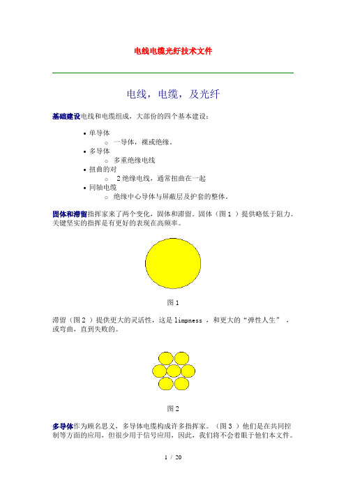
电线电缆光纡技术文件电线,电缆,及光纤基础建设电线和电缆组成,大部份的四个基本建设:•单导体o一导体,裸或绝缘。
•多导体o多重绝缘电线•扭曲的对o 2绝缘电线,通常扭曲在一起•同轴电缆o绝缘中心导体与屏蔽层及护套的整体。
固体和滞留指挥家来了两个变化,固体和滞留。
固体(图1 )提供略低于阻力。
关键坚实的指挥是有更好的表现在高频率。
图1滞留(图2 )提供更大的灵活性,这是limpness ,和更大的“弹性人生” ,或弯曲,直到失败的。
图2多导体作为顾名思义,多导体电缆构成许多指挥家。
(图3 )他们是在共同控制等方面的应用,但很少用于信号应用,因此,我们将不会着眼于他们本文件。
扭曲的对对扭曲(图4 )连续两个绝缘电线扭在一起。
他们是专为进行信号和发明,在1880年的接线了早期的系统。
扭曲对提供低噪声上升和低噪音的排放量从有线电视,因为它是一个均衡的路线,因为一个平衡的路线,提供了“共同模式的噪音抑制” 。
什么是一个均衡的界线呢?一个平衡的路线,是一个配置2线保持着密切在一起,通常由他们扭(图5 )。
导体必须相同长度,相同的大小,与不断之间的距离。
图5应该指出的是,信号,在任何即时在时间,是完全一样的,但相反极性的就两个电线。
另一种方式的说是,如果你注意信号电压在任何一点的电缆,他们累加起来应为零。
当噪音出现… … 。
噪音是生活中的事实。
这是电磁辐射,并可以来自许多来源,包括荧光照明,电机,汽车点火系统,设备,如医院,分析仪,传输设备,由立法会CB的,卡车,的士,电台和电视台,和自然来源,如太阳。
当噪音出现,并击中两个电线在我们的扭曲对(图6 ),电磁辐射噪声诱导电压,在双方的电线。
不过,方向是相同的或“共同模式”在双方的电线。
图6当两个噪声信号到达两端的电缆,有一种被动的平衡装置(如变压器显示,在图6 )或等值的积极平衡的投入。
你可以看到,两个噪声信号对两个电线取消对方。
这样一来,取消了噪音和信号(这是“差模” )可以继续通过。
WiFi基础知识介绍

WiFi Test Configuration For R&D (conducted)
USB
RF Cable
WiFi Module
N4010A
USB / PCI-E
3.2 Board Level Test For Production Line (Conducted) Test Purpose Verification RF performance can meet IEEE 802.11 b/g standard Test Item Transmit power Transmit center frequency tolerance Rx PER Tx PER Rx Throughput
3.3 WiFi Board Level Test Configuration For Production Line
GPIB
11713B
3.4 WiFi System Level Test (Radiation)
– Test Purpose • Connect to AP to verify user application performance – Test Item • Throughput Test • File Transmission Time • RSSI (Receiving Signal Strength Indicator)
2 IEEE 802.11家族技朮 家族技朮
2.1 IEEE 802.11a
2.2 IEEE 802.11b
2.3 IEEE 802.11g
2.4 IEEE 802.11n
物理层
MIMO(多入多出 )和OFDM的无线LAN技术。 工作频段: 2.4GHz , 高达600 Mbps的传输速 率 。
Agilent PNA系列RF网络分析器扩频范围升级套件说明书
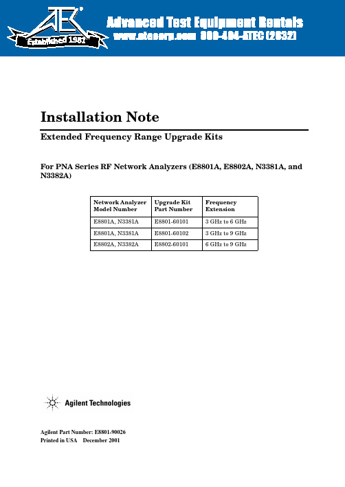
Agilent Part Number:E8801-90026Printed in USADecember2001Installation NoteExtended Frequency Range Upgrade KitsFor PNA Series RF Network Analyzers (E8801A,E8802A,N3381A,and N3382A)Network Analyzer Model Number Upgrade Kit Part Number Frequency Extension E8801A,N3381A E8801-601013GHz to 6GHz E8801A,N3381A E8801-601023GHz to 9GHz E8802A,N3382AE8802-601016GHz to 9GHz1981Notice.The information contained in this document is subject to change without notice.Agilent Technologies makes no warranty of any kind with regard to this material,including but not limited to,the implied warranties of merchantability and fitness for a particular purpose.Agilent shall not be liable for errors contained herein or for incidental or consequential damages in connection with the furnishing, performance,or use of this material.©Copyright2001Agilent Technologies,Inc.All rights reserved.About the Upgrade KitsProducts affected..........................E8801A,E8802A,N3381A,and N3382A;all options(See NOTE below.)Installation to be performed by..............Agilent service center,personnel qualifiedby Agilent,or customerEstimated installation time.................E8801A and N3381A–15minutesE8802A and N3382A–5minutesEstimated verification time.................5minutesEstimated calibration adjustment time........45minutesNOTE If the Time Domain option,Option010,is already installed on your analyzer,you will need a new license key for that option to function after installation of thefrequency upgrade.Contact Agilent for this new license key.If you need assistance,refer to“Getting Assistance from Agilent”on page5.Description of the UpgradesThese upgrade kits are used to extend the frequency range of the:•E8801A or N3381A PNA RF network analyzer from3GHz to either6GHz or9GHz•E8802A or N33802A PNA RF network analyzer from6GHz to9GHzInstallation Note E8801-900263Items Included in the Upgrade KitsThe following three tables list the parts included in the upgrade kits for the affected network analyzers.Check the contents of your kit against the appropriate list.If any item is missing or damaged,contact Agilent Technologies.Refer to“Getting Assistance from Agilent”on page5.Table1Option006Upgrade Kit to Extend the E8801A or N3381A to6GHz (E8801-60101)Description Qty Part Number Installation note(this document)1E8801-90026 License key certificate15964-5136Model number nameplate1E8802-80001 Model number nameplate1N3382-80001A12source assembly1E8803-60062 Table2Option009Upgrade Kit to Extend the E8801A or N3381A to9GHz (E8801-60102)Description Qty Part Number Installation note(this document)1E8801-90026 License key certificate15964-5136Model number nameplate1E8803-80001 Model number nameplate1N3383-80001A12source assembly1E8803-60062 Table3Option009Upgrade Kit to Extend the E8802A or N3382A to9GHz (E8802-60101)Description Qty Part Number Installation note(this document)1E8801-90026 License key certificate15964-5136Model number nameplate1E8803-80001 Model number nameplate1N3383-800014Installation Note E8801-90026Getting Assistance from AgilentBy internet,phone,or fax,get assistance with all your test and measurement needs. Table4Contacting AgilentOnline assistance:/find/assistUnited States (tel)180********Latin America(tel)(305)2697500(fax)(305)2697599Canada(tel)187********(fax)(905)282-6495Europe(tel)(+31)205472323 (fax)(+31)205472390Australia(tel)1800629485(fax)(+61)392105947New Zealand(tel)0800738378(fax)(+64)44958950Japan(tel)(+81)426567832 (fax)(+81)426567840Singapore(tel)180********(fax)(65)8360252Malaysia(tel)1800828848(fax)1800801664India(tel)1600112929 (fax)0008006501101Hong Kong(tel)800930871(fax)(852)25069233Taiwan(tel)0800047866(fax)(886)225456723Philippines(tel)(632)8426802(tel)(PLDT subscriber only) 180016510170(fax)(632)8426809(fax)(PLDT subscriber only) 180016510288Thailand(tel)(outside Bangkok)(088)226008(tel)(within Bangkok)(662)6613999(fax)(66)16613714People’s Republic of China(tel)(preferred)8008100189(tel)(alternate)108006500021(fax)108006500121Installation Note E8801-9002656Installation Note E8801-90026Installation Procedurefor the Upgrade KitThe network analyzer must be in proper working condition prior to installing this option.Any necessary repairs must be made before proceeding with this installation.WARNINGThis installation requires the removal of the analyzer’s protective outer covers.The analyzer must be powered down and disconnected from the mains supply before performing this procedure.Electrostatic Discharge ProtectionProtection against electrostatic discharge (ESD)is essential while removing or connecting cables or assemblies within the network analyzer.Static electricity can build up on your body and can easily damage sensitive internal circuit elements when discharged.Static discharges too small to be felt can cause permanent damage.To prevent damage to the instrument:•always wear a grounded wrist strap having a 1M 9resistor in series with it when handling components and assemblies.•always use a grounded,conductive table mat while working on the instrument.•always wear a heel strap when working in an area with a conductive floor.If you are uncertain about the conductivity of your floor,wear a heel strap.Figure 1shows a typical ESD protection setup using a grounded mat and wrist strap.Refer to “Tools and Equipment Required for the Installation”on page 7for part numbers.Figure 1ESD Protection SetupOverview of the Installation ProcedureNote that step2is necessary only for the E8801A and N3381A network analyzers because they require a new A12source assembly.1.Verify the serial and option numbers of the analyzer.2.Replace the A12source assembly(E8801A and N3381A only).3.Enter the new model number.4.Verify that the new model number is shown correctly.5.Replace the model number nameplate on the front panel.6.Perform source and receiver calibration adjustments.Tools and Equipment Required for the InstallationDescription Model/Part Number Tools for A12Source Assembly Replacement(E8801A and N3381A Only)T-10TORX driver(set to9in-lbs)N/AT-20TORX driver(set to21in-lbs)N/A5/16-inch open-end torque wrench(set to10in-lb)N/AESD EquipmentESD grounding wrist strap9300-13675ft grounding cord for wrist strap9300-09802x4ft conductive table mat and15ft grounding wire9300-0797ESD heel strap(for use with conductive floors)9300-1308Test Equipment for Calibration AdjustmentsPower meter E4419BPower sensor(100kHz–4.2GHz)8482APower sensor(10MHz–18GHz)E4412AType-N adapter(female-to-female)1250-0777Type-N RF cable N6314AStep1.Verify the Serial and Option Numbers of the AnalyzerRefer to the License Key Certificate supplied with the kit:•Verify that the analyzer’s serial number matches the serial number on the certificate.•Verify that the option number on the certificate is correct:M02for an E8801A6GHz upgrade;M03for an E880xA9GHz upgrade;M82for an N3381A6GHz upgrade;M83for an N338xA9GHz upgrade.If either the serial number or the option number does not match the expected results,you will not be able to install the option.If this is the case,contact Agilent for assistance.Refer to “Getting Assistance from Agilent”on page5.Installation Note E8801-900267Step2.Replace the A12Source Assembly(E8801A and N3381A Only) This step is necessary only for the E8801A and N3381A network analyzers.If installing an upgrade kit for the E8802A or N3382A network analyzer,proceed to Step3.Remove the Outer and Inner Covers from the AnalyzerRefer to Figure2for this procedure.Remove the Outer CoverCAUTION This procedure is best performed with the analyzer resting on its front handles in the vertical position.Do not place the analyzer on its front panel without thehandles.This will damage the front panel assemblies.1.Disconnect the power cord(if it has not already been disconnected).2.With a T-20TORX driver,remove the strap handles(item )by loosening the screws (item )on both ends until the handle is free of the analyzer.3.With a T-20TORX driver,remove the four rear panel feet(item )by removing the center screws(item ).4.Slide the four bottom feet(item )off the cover.5.Slide the cover off of the frame.Remove the Inner Cover1.With a T-10TORX driver,remove the15screws(item ).2.Lift off the cover.8Installation Note E8801-90026Installation Note E8801-900269Figure2Outer and Inner Cover Removal10Installation Note E8801-90026Replace theA12Source Assembly Refer to Figure 3for this step.1.Place the A31hard disk drive assembly in the service position.a.With a T-10TORX driver,remove the mounting screw (item).b.Move the HDDA to the outside of the analyzer and slide the HDDA bracket feet into the slots on the frame to the horizontal position.This is the service position.Figure 3Placing the A31HDDA in the Service PositionRefer to Figure 4for the following steps.2.Disconnect the two flexible cables (item )from the A12source assembly being careful to note their locations for reconnection later.CAUTIONBe careful not to damage the center pins of the semirigid cables.Some flexing of the cables is necessary to remove the assembly.Do not over-bend the semirigid cables.3.With a 5/16-in torque wrench,disconnect the two semirigid cables (item )from thebottom of the A12source assembly.CAUTIONTo avoid damage to the semirigid cables (item ),pull down on the cables from the bottom of the analyzer to move them away while sliding out the A12source assembly.The cables have some spring to them and the RF pins could be damaged by the A12source assembly .4.Slide the A12source assembly out of the analyzer.5.Slide the new A12source assembly into the analyzer being careful not to damage the semirigid cables.Refer to the CAUTION s above.6.With a5/16-in torque wrench,reconnect the two semirigid cables(item¦ )to the bottomof the A12source assembly.7.Reconnect the two flexible cables(item )to the A12source assembly.Refer to Figure3for the following steps.8.Reinstall the A31hard disk drive assembly into its original position.9.With a T-10TORX driver,replace the mounting screw(item )Figure4A12Source Assembly ReplacementReinstall the Inner and Outer CoversRefer to Figure5for this procedure.Reinstall the Inner Cover1.Place the inner cover on the analyzer.There are two alignment pins on the front framethat must be aligned with holes in the cover.2.With a T-10TORX driver,install the15screws(item ).Reinstall the Outer CoverCAUTION This procedure is best performed with the analyzer resting on its front handles in the vertical position.Do not place the analyzer on its front panel without thehandles.This will damage the front panel assemblies.1.Slide the cover onto the frame.2.With a T-20TORX driver,install the four rear panel feet(item )by installing the center screws(item ).3.Slide the four bottom feet(item )onto the cover.4.With a T-20TORX driver,install the strap handles(item )by tightening the screws(item )on both ends.Figure5Inner and Outer Cover ReinstallationStep3.Enter the New Model NumberProcedure Requirements•The analyzer must be powered up and operating to perform this procedure.•The Network Analyzer program must be running.•A keyboard is required for this procedure.•A mouse is recommended for this procedure but is not required.Mouse Procedure1.On the analyzer’s System menu,point to Service,then click Option Enable.2.Click Repair.3.Check Model shown is incorrect!,then click Begin Repair.4.In the Model Change box,select the appropriate new model number:E8802A or N3382A(for the6GHz upgrade)or E8803A or N3383A(for the9GHz upgrade).ing the keyboard,enter the keyword in the box provided.The keyword is printed on theLicense Key Certificate.Enter this keyword exactly as it is printed on the certificate.6.Click Enter Model.7.Verify that the new model number displayed is correct,then click YES.If it is not correct,click NO and repeat the repair.8.When the installation is complete,click Exit.Front Panel Keys Procedure1.In the COMMAND block,press Menu/Dialog.2.In the NAVIGATION block,press the Right Tab and Arrows to move over to the Systemmenu and down to the Service selection.Press the Right Tab to display the extended menu and the Arrows to select Option Enable.Press Click.3.Press Menu/Dialog,then press R on the keyboard to select Repair.4.Tab to Model shown is incorrect!,then press Click.5.Tab to the Model Change box,then use the Arrows to select the appropriate new modelnumber:E8802A or N3382A(for the6GHz upgrade)or E8803A or N3383A(for the9GHz upgrade).6.Tab to the Keyword box and,using the keyboard,enter the keyword.The keyword isprinted on the License Key Certificate.Enter this keyword exactly as it is printed on the certificate.7.Tab to Enter Model,then press Click.8.Verify that the new model number displayed is correct,then tab to Yes and press Click.Ifit is not correct,tab to NO,press Click,and repeat the repair.9.When the installation is complete,Tab to Exit,then press Click.Step4.Verify that the New Model Number Is Shown Correctly Procedure Requirements•The analyzer must be powered up and operating to perform this procedure.•The Network Analyzer program must be running.•A mouse is recommended for this procedure but is not required.Mouse Procedure1.On the analyzer’s Help menu,click About Network Analyzer.2.Verify that the new model number is shown correctly in the display.Click OK.3.On the analyzer front panel,press Preset.Verify that the full frequency range of theanalyzer is correct.Front Panel Keys Procedure1.In the COMMAND block,press Menu/Dialog.2.In the NAVIGATION block,press the Right Tab and Arrows to move over to the Help menu,and down to the About Network Analyzer selection.Press Click.3.Verify that the new model number is shown correctly,then press Click.4.On the analyzer front panel,press Preset.Verify that the full frequency range of theanalyzer is correct.Step5.Replace the Model Number Nameplate on the Front Panel Refer to Figure6for this procedure.Remove the Old Nameplateing a sharp object such as a knife blade,lift one end of the old nameplate(item ).Becareful not to scratch the painted surface.ing your fingers,pull the nameplate completely off of the front panel and discard it.3.If any adhesive remains on the front panel surface,it can be removed by rubbing it withyour finger.Do not use a sharp object to remove this adhesive.If necessary,the surface can be cleaned with isopropol alcohol.Install the New NameplateNOTE There are two nameplates provided in the upgrade kit.Make sure that you install the correct one for your analyzer.The E8802A and E8803A nameplatesare for2-port analyzers,and the N3382A and N3383A nameplates are for3-portanalyzers.1.Remove the protective backing from the new nameplate to expose the adhesive.Avoidtouching the adhesive with your fingers as this may affect its ability to adhere to the front panel surface.2.Loosely align the new nameplate over the recess in the front panel and apply lightly.3.Once the overlay is properly aligned,press it firmly onto the surface to secure it.Figure6Model Number Nameplate ReplacementStep6.Perform Source and Receiver Calibration AdjustmentsThe following adjustments must be made due to the change in the full frequency range of the analyzer.Source Calibration AdjustmentThe source calibration is used to adjust your network analyzer for a flat source power across its full frequency range.The differences between Port1and Port2are negligible;therefore,a Port2adjustment is not required.1.Connect the equipment as shown in Figure7.Connect a GPIB cable between the networkanalyzer and the power meter.Figure7Setup for the Source Calibration Adjustment2.On the System menu,point to Service,Adjustments,then click Source Calibration.3.Ensure the GPIB settings are correct.4.Click Calibrate,then follow the instructions as they are displayed.Receiver Calibration AdjustmentThe receiver calibration is used to adjust the network analyzer receivers for a flat response across its full frequency range.A power meter is connected to Port1,as shown inFigure8,to establish a reference for flatness.A signal from Port1,as shown inFigure9,is used to adjust the“B”receiver at Port2.The adjustment is repeated using a signal from Port2to adjust the“A”receiver at Port1.1.Connect the equipment as shown in Figure8.Connect a GPIB cable between the networkanalyzer and the power meter.Figure8Setup for the Receiver Calibration AdjustmentFigure9Setup for the Receiver Calibration Adjustment of Port22.On the System menu,point to Service,Adjustments,then click Receiver Calibration.3.Ensure the GPIB settings are correct.4.Click Calibrate,then follow the instructions as they are displayed.Performance Tests and System VerificationThe analyzer should now operate and phase lock over its entire frequency range.If you experience difficulty with the basic functioning of the analyzer,contact Agilent.Refer to “Getting Assistance from Agilent”on page5.Although the analyzer functions,its performance relative to its specifications has not been verified for the additional frequency range enabled by this upgrade.It is recommended that a full instrument calibration be performed using the N2721A performance test software.If the testing of the analyzer’s full range of specifications is not required,a system verification can be performed.Refer to the analyzer’s Service Guide for information on performance tests and system verification.。
干扰测试仪E7495A

1E7495A/B Manual Operation / Verification 7495Manual Verification Procedures The Manual verification procedures allow you to check out the functionality of the major sections of the hardware that do not have automated On-board Verification Tests. Verifying the E7495A/B RF Functionality Verifying the CW Source Functionality (Option 500/510 only) Verifying the Complex Modulation Functionality (Option 510 only) Verifying the Power Meter Functionality (Option 600 only) Battery Management VerificationTestsA3 RF FunctionalityVerifying the E7495A/B RF FunctionalityThe base product of the E7495A/B consists of two main blocks: Sourceand Receiver. The antenna/cable measurements use both of these blocksand, using the Insertion Loss and Return Loss measurements, verifythe correct operation of both the source and receiver.Test equipment• 2 - 10 dB Type-N pads (Part of E7495A/B Cal kit)•Short Type-N cable (Part of E7495A/B Cal kit)•6, 20, and 30 dB 849xx series Type-N pads or a 10 dB step attenuatorInsertion loss procedure1.Press [MODE] Antenna/Cable, Two Port Insertion Loss.2.Set the Start Frequency to 375 MHz; Stop Frequency to 2500 MHz.3.Press Setup, Optimize and verify it is set to Accuracy.4. Connect the two 10 dB pads and a short Type-N cable as shown inFigure 1 on page 2.Figure 1Connect the 10 dB pads.23 A3 RF Functionality74955.Press Frequency/Normalize and follow the instructions.The junction of the 10 dB pads forms a calibrated plane. Measuring unknowns or standards is performed by splitting the plane and inserting the unknown or standard between the 10 dB pads.6.Connect the 6 dB pad between the two 10 dB pads.e the marker function to verify that the measured value agrees with the pad.8.Repeat steps 6 and 7, using different pads in order to cover the range of 6 – 60 dB.Return Loss procedure 1.Press [MODE ] Antenna/Cable test ; Return Loss .2.Set the Start Frequency to 375 MHz , Stop Frequency to 2500 MHz .3.Perform the open/load and short calibration.4.Connect a 6 dB pad to the end of the cable connected to Port 1.5.Average/Sweep turn off averaging to clear the buffer.6.Turn on averaging.The best and worst return loss should be between 10 and 14 dB.If you find a failure•Double-check your attenuators! When you stack attenuators the overall insertion loss is slightly higher than the sum of the values. •Check the Port 1 and Port 2 Type-N connectors for contamination, damage, or loose connectors.•Reload the latest firmware.In the event of a performance failure, you must have the instrument sent in for repair.CW Source FunctionalityVerifying the CW Source Functionality (Option 500/510 only) The optional CW source uses the same internal source as is used for the antenna cable measurements. The option adds an internal step 5 dB attenuator to increase the output range.Test equipment•Spectrum analyzer•Type-N cableTest procedureYou will connect the source directly to the spectrum analyzer’s input and step the CW source in 1 dB increments while reading the spectrum analyzer’s peak marker. The value should always be within 2 dB of the CW sources stated output.1. Perform the RF Functionality test procedure on page2.2.Verify the step attenuator’s functionality.On the E7495A/B1.Press [Mode], Spectrum/Tools.2.Press Signal Generator.3.Set the units to Frequency.4.Set the frequency to 375 MHz.5.Set the amplitude step to 2 dB.6.Set the amplitude to –25 dBm.7.Turn the RF On.On the Spectrum Analyzer1.Set the frequency to 375 MHz.2.Set the span to 10 KHz.3.Increase the resolution BW to 1 KHz, if the update rate is very slow.4.Set the Reference Level to –25 dBm.5.Press Marker Peak Search.6.While you watch the marker readout on the spectrum analyzer, stepthe E7495A/B amplitude from – 25 to –89 dBm by pressing the down arrow.The Marker amplitude should show a 2 dB ± .5 dB change for each press of the down arrow. Any amplitude should be within 2 dB (± the uncertain of the spectrum analyzer used).45 CW Source Functionality 7495If you find a failure •Reload the latest firmware and repeat the test.If the test results are slightly outside the stated limits •Verify the connectors are clean and the connections are tight. In the event of a performance failure the instrument must be sent in for repair.Complex Modulation VerificationVerifying the Complex Modulation Functionality (Option 510 only) The Complex Modulation option adds a DSP and a special DAC in orderto output complex signals such as CDMA and CDMA2000. The outputof the DAC is mixed with the CW Source to set the output frequency.The CW signal is not suppressed so you can see a signal ~60 MHz awayfrom the set frequency.There are seven different waveforms that can be output in the Complex Modulation mode. Generally, if one works, they all will.Test equipment•Spectrum analyzer•Type-N cableTest procedureOn the E7495A/B1.Press [Mode], Spectrum/Tools.2.Press Signal Generator.3.Set the units to Frequency.4.Set the frequency to 375 MHz.5.Set the modulation to CW.6.Set the amplitude to –50 dBm.7.Turn the RF On.On the Spectrum Analyzer8.Set the frequency to 375 MHz.9.Set the span to 2 MHz.10.Set the reference level to –45 dBm.11.Press Marker Peak Search.12.Verify the amplitude of the CW signal is –50 dBm ± 2 dB.13.On the E7495A/B, change the modulation to CDMA Forward LinkPilot Only w/o Eq.14.On the Spectrum Analyzer, you should see a broad spectrum signalapproximately 1.23 MHz wide.15.Check each of the modulations available. They should all look thesame as the CDMA Forward link Pilot only.16.Repeat steps 1 – 13 at 2.49 GHz.67 Complex Modulation Functionality 7495If you find a failure •If one or more complex modulation types look correct but others don’t, reload the latest firmware and repeat the test.•In order to test against any limits, you must have a spectrum analyzer that can measure channel power or a device capable of demodulating and measuring complex signals. In the event of a performance failure, you must send the instrument in for repair. Verifying the Power Meter Functionality (Option 600 only)The Power Meter option uses the same measuring hardware as the E4418B Power Meter. The capabilities are modified for use with the Base Station Test market. Test equipment •8482A power sensor and cableTest procedure•For a basic checkout, if you are able to zero and cal the sensor, the circuit is functioning correctly.If you find a failureIf the meter does not respond to any controls or the controls are grayed out:• Check that the power meter option is enabledIf the meter does not zero or calibrate check or replace the following:• Power Sensor Cable• Reload the instrument firmware• Power SensorIf the power meter is still not functioning properly it must be sent in for repair.Battery Management FunctionalityBattery Management VerificationTestsDefinitionThe Battery Management Functional Test verifies the functionality of the E7495A/B battery charge/discharge circuitry, and it’s ability to switch between Battery and External DC Power.The Battery Management Functional Test is a manual test. This procedure is comprised of 4 tests to check out the Power Management functionality:•External DC Power Test – Verifies the Test Set’s ability to operate off of External DC Power. During the External DC Power Test, theoperator will verify the status of the Display Icons and the FrontPanel Battery LED’s while operating on EXT DC Power.•Internal Battery Power Test – Verifies the Test Set’s ability to operate off of the Internal Battery(s). During the Internal Battery Power Test, the operator will verify the status of the Display Icons and the Front Panel Battery LED’s while operating on BatteryPower.•Battery Charge Statistics- Verifies the Test Set’s ability to control the charge functionality, communicate and Display the Data received from the Battery. During this test the operator will verify the status of the Display Icons, the Front Panel Battery LED’s, and the Battery Statistics Screen.•Battery Discharge Statistics – Verifies the Test Set’s ability to switch between Batteries and control the discharge functions of the Battery Controller board. During this test the operator will verify the status of the Display Icons, the Front Panel Battery LED’s, and the Battery Statistics Screen.89Battery Management Functionality Step 3 - Verify Test Set Functionality 7495If any of the above tests fail:1.Insure the External DC Power Supply is functioning properly.2.Insure the Battery is functioning properly, a recondition of the battery may be necessary .Test Equipment AC to DC Power Supply (supplied with E7495A/B)0950-4404NI2040AG Battery (supplied with E7495A/B)1420-0883If the external DC Power Supply and Battery are functioning properly and any of the above tests fail, the instrument will need to be sent in for repair.B a t t e r y M a n a g e m e n t F u n c t i o n a l i t yRunning the Battery Management Functional TestNOTE When connecting or removing the Ext DC Power, the E7495A/B Test Set can take up to 20 seconds for the Battery Status Indicators to update.1.External DC Power TestSetup•Install battery into Battery Position #2 (Closest to the back ofthe E7495A/B case)•Plug the Ext DC power into the E7495A/B•Turn the Ext DC power supply’s switch to on•Turn the E7495A/B on and allow it to fully power-upTest Results•On the Front Panel Display, verify that the External DC icon(Plug icon) is present on the lower right hand portion of thedisplay.•Verify that the Battery Icons on the Front Panel Displayaccurately represent the condition of the installed battery.1011 Battery Management Functionality 7495•Verify that the Front Panel Battery LED’s accurately indicates the correct status of the battery(s) installed in the Test Set.Battery 1:(Light Grey: No Battery Installed)Battery 2 should be one of the following:(Green: Greater than 25% Charge remaining)(Yellow: 10 to 15% Charge remaining)(Red: Less than 10% Charge remaining)(Dark Grey: No Charge remaining)Battery 1:(Off: No Battery Installed)Battery 2should be one ofthe following:(Blinking Green: Battery is Charging)(Solid Green: Battery in Fully Charged)Battery Management Functionality2.Internal Battery Power TestSetup•Insure a battery with >10% charge is installed in Battery Position #2•Remove the Ext DC Power from the E7495A/BTest Results•On the Front Panel Display, verify the External DC icon (Plug icon) is NOT present on the lower right hand portion of thedisplay.•Verify the Battery Icons on the Front Panel Display accurately represent the condition of the installed battery.Battery 1:(Light Grey: No Battery Installed)Battery 2should be one of the(Green: Greater than 25% Charge remaining)following:(Yellow: 10 to 15% Charge remaining)(Red: Less than 10% Charge remaining)(Dark Grey: No Charge remaining)1213Batte r y Management Functionality 7495•Verify that the Front Panel Battery LED’s accurately indicates the correct status of the battery(s) installed in the Test Set.Battery 1:(Off: No Battery Installed)Battery 2 should be one ofthe following:(Green: Greater than 25% chargeremaining)(Yellow: 10 to 25% charge remaining)(Red: Less than 10% charge remaining)Battery Management Functionality3.Battery Charge StatisticsSetup•Reconnect the Ext DC power to the E7495A/B.•Insure a charged battery is installed in the E7495A/B in Battery Position #2.Test Results•Access the Battery Statistics Screen—Press the [System] Key—Press the [More 1 of 2] Softkey—Press the [System Stats] Softkey—Press the [Battery] Softkey•Verify the following fields on the Battery Status Screen with a Battery in Battery Position #2 only.Battery Status•Battery 1 field = Missing•Battery 2 field = PresentRun Time to Empty•Battery 1 field = ----•Battery 2 field = External DC Power1415 B attery Management Functionality 7495 4.Battery Discharge Statistics Setup •Move Battery to Battery Position #1 (closest to the Front Display)•Remove the Ext DC Power from the E7495A/B Test Results •Verify the following fields on the Battery Status Screen with a Battery in Battery Position #1 only Battery Status •Battery 1 field = Present •Battery 2 field = Missing Run Time to Empty •Battery 1 field = XXX Minutes (XXX should be 10 or greater for a battery with 10% charge)•Battery 2 field = ----。
RF设备技术规范说明书
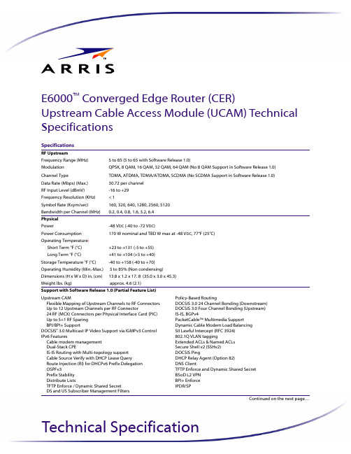
Technical SpecificationSpecificationsRF UpstreamFrequency Range (MHz)5 to 85 (5 to 65 with Software Release 1.0)ModulationQPSK, 8 QAM, 16 QAM, 32 QAM, 64 QAM (No 8 QAM Support in Software Release 1.0)Channel TypeTDMA, ATDMA, TDMA/ATDMA, SCDMA (No SCDMA Support in Software Release 1.0)Data Rate (Mbps) (Max.)30.72 per channel RF Input Level (dBmV)-16 to +29Frequency Resolution (KHz)< 1Symbol Rate (Ksym/sec)160, 320, 640, 1280, 2560, 5120Bandwidth per Channel (MHz)0.2, 0.4, 0.8, 1.6, 3.2, 6.4PhysicalPower-48 V DC (-40 to -72 V DC )Power Consumption170 W nominal and TBD W max at -48 V DC , 77°F (25°C)Operating Temperature :Short Term °F (°C)+23 to +131 (-5 to +55)Long Term °F (°C)+41 to +104 (+5 to +40)Storage Temperature °F (°C)-40 to +158 (-40 to +70)Operating Humidity (Min.-Max.)5 to 85% (Non condensing)Dimensions (H x W x D) in. (cm)13.8 x 1.2 x 17. 8 (35.0 x 3.0 x 45.3) Weight lbs. (kg)approx. 4.6 (2.1)Support with Software Release 1.0 (Partial Feature List)Upstream CAM Flexible Mapping of Upstream Channels to RF Connectors Up to 12 Upstream Channels per RF Connector 24 RF (MCX) Connectors per Physical Interface Card (PIC)Up to 5+1 RF Sparing BPI/BPI+ Support DOCSIS ®3.0 Multicast IP Video Support via IGMPv3 Control IPv6 Features Cable modem management Dual-Stack CPE IS-IS Routing with Multi-topology support Cable Source Verify with DHCP Lease Query Route Injection (RI) for DHCPv6 Prefix Delegation OSPFv3Prefix Stability Distribute Lists TFTP Enforce / Dynamic Shared Secret DS and US Subscriber Management FiltersPolicy-Based RoutingDOCSIS 3.0 24 Channel Bonding (Downstream)DOCSIS 3.0 Four Channel Bonding (Upstream)IS-IS, BGPv4PacketCable™ Multimedia SupportDynamic Cable Modem Load BalancingSII Lawful Intercept (RFC 3924)802.1Q VLAN taggingExtended ACLs & Named ACLsSecure Shell v2 (SSHv2)DOCSIS PingDHCP Relay Agent (Option 82)DNS ClientTFTP Enforce and Dynamic Shared SecretBSoD L2 VPNBPI+ EnforceIPDR/SPContinued on the next page…E6000™Converged Edge Router (CER)Upstream Cable Access Module (UCAM) Technical SpecificationsARRIS Technical SpecificationsOrdering InformationPart Number DescriptionUCAM Kits799008E6000 CER 48 US UCAM Kit (Active) -1 UCAM, Active UCAM PIC, and 48 DOCSIS US Licenses801026E6000 CER 48 US UCAM Kit (Spare) -1 UCAM, Spare UCAM PIC, and 48 DOCSIS US Licenses802221E6000 CER 96 US UCAM Kit (Active) -1 UCAM, Active UCAM PIC, and 96 DOCSIS US Licenses802222E6000 CER 96 US UCAM Kit (Spare) -1 UCAM, Spare UCAM PIC, and 96 DOCSIS US LicensesLicense Bundles801062E6000 CER 48 DOCSIS US License BundleMaintenance Plan (required)801169E6000 Software Maintenance –Phone Plus GoldSpecifications are subject to change without notice.The capabilities, system requirements and/or compatibility with third-party products described herein are subject to change without notice. ARRIS, the ARRIS logo,Auspice®, BigBand Networks®, BigBand Networks and Design®, BME®, BME 50®, BMR®, BMR100®, BMR1200®, C3™, C4®, C4c™, C-COR®, CHP Max5000®,ConvergeMedia™, Cornerstone®, CORWave™, CXM™, D5®, Digicon®, E6000™, ENCORE®, EventAssure™, Flex Max®, FTTMax™, HEMi®, MONARCH®, MOXI®, n5®,nABLE®, nVision®, OpsLogic®, OpsLogic® Service Visibility Portal™, Opti Max™, PLEXiS®, PowerSense™, QUARTET®, Rateshaping®, Regal®, ServAssure™, ServiceVisibility Portal™, TeleWire Supply®, TLX®, Touchstone®, Trans Max™, VIPr™, VSM™, and WorkAssure™ are all trademarks of ARRIS Group, Inc. Other trademarks andtrade names may be used in this document to refer to either the entities claiming the marks and the names of their products. ARRIS disclaims proprietary interest inthe marks and names of others. © Copyright 2013 ARRIS Group, Inc. All rights reserved. Reproduction in any manner whatsoever without the express writtenpermission of ARRIS Group, Inc. is strictly forbidden. For more information, contact E6000UCAM_TS_20FEB13。
TESCOM RF电缆及RF接头说明
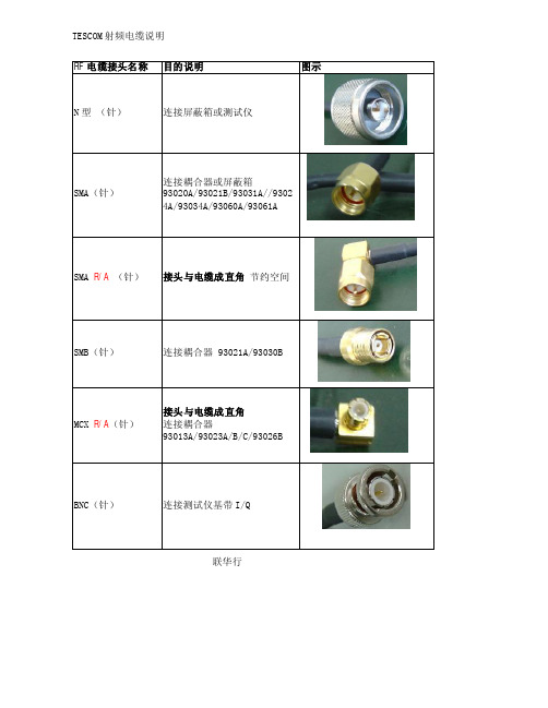
联华行
N 型 (针) 连接屏蔽箱或测试仪
SMA (针)
连接耦合器或屏蔽箱
93020A/93021B/93031A//9302 4A/93034A/93060A/93061A
SMA R/A (针) 接头
与电缆成
直角 节约空间
SMB (针) 连接耦合器 93021A/93030B
MCX R/A (针)
接头
与电缆成
直角 连接耦合器
93013A/93023A/B/C/93026B
BNC (针) 连接测试仪基带I/Q
1. 请使用原厂电缆,以免损坏耦合器或屏蔽箱。
2. 连接射频接头时,请使用
双手,必
须对正,先逆时针转动,以免损坏螺纹 3. RF 电缆有插拔寿命,3000次。
使用中减少插拔可延长电缆寿命。
4005-0035(棕细) 材质:RG316D
1. 2.4GHz 屏蔽箱内使用
连接耦合器与屏蔽箱
2. 用耦合器进行音频测试 连接音频测试仪和耦合器
4002-0002(黑粗) 材质:RG223
北京联华行
2.4GHz 屏蔽箱外使用
连接测试仪与屏蔽箱
4006-0004(棕粗) 材质:RG400S 2.4GHz 屏蔽箱外使用 连接测试仪与屏蔽箱
4011-0004(蓝粗) 材质:SS402 5.8GHz 屏蔽箱外使用 连接测试仪与屏蔽箱
4011-0011(蓝细) 材质:SS406 5.8GHz 屏蔽箱内使用 连接耦合器与屏蔽箱
RF 电缆标志
型号:4011-0011
材质:SS406 长度:60cm
线损 CableLoss
每个电缆都提供不同频点线缆 的损耗。
WT160 WLAN Test Solution Presentation

技术领先
高性价比
- 内置WLAN Meter,支 持研发手动测试 - 配置WLAN Facility,支 持生产自动化测试 - 本地化研发/生产降低研 发、生产、物流等成本
Xgiga Technologies Co., Ltd
WLAN Meter
VSA
Xgiga Technologies Co., Ltd
WLAN Meter
VSG
Xgiga Technologies Co., Ltd
WLAN Meter特性
Auto Range功能能自动调整测试档位,快速得到准确测试结果 提供Free Run、Signal、External三种触发方式 测试项目包括: 信号功率(Power) EVM 接收灵敏度/PER 频谱模板(Spectrum Mask) CCDF 星座图 载波EVM 眼图等等
可根据客户产品定制产测软件
Xgiga Technologies Co., Ltd
测试速度对比 —— Facility VS Another Solution
以RT3052-DUT为例,在测试项目(Test Flow)完全一样的情况下: Facility测试时间:56.8s Another Solution测试时间:84.4s Facility测试速度比Another Solution快47%
RF电缆
WT-160测试解决方案包含:
WT-160测试仪 WLAN Meter研发测试软件(安装在PC) WLAN Facility生产测试软件(安装在PC) 被测设备DUT
WR-UMRF RPSMA 斜角插座说明书
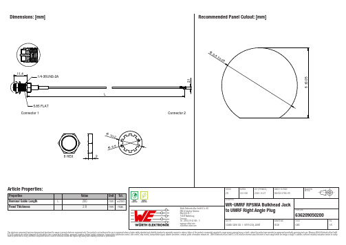
636209050200636209050200636209050200636209050200Cautions and Warnings:The following conditions apply to all goods within the product series of the Connectors of Würth Elektronik eiSos GmbH & Co. KG:General:•This mechanical component is designed and manufactured for use in general electronic equipment.•Würth Elektronik must be asked for written approval (following the PPAP procedure) before incorporating the components into any equipment in fields such as military, aerospace, aviation, nuclear control, submarine, transportation (automotive control, train control, ship control), transportation signal, disaster prevention, medical, public information network, etc. where higher safety and reliability are especially required and/or if there is the possibility of direct damage or human injury.•Mechanical components that will be used in safety-critical or high-reliability applications, should be pre-evaluated by the customer.•The mechanical component is designed and manufactured to be used within the datasheet specified values. If the usage and operation conditions specified in the datasheet are not met, the component may be damaged or dissolved.•Do not drop or impact the components, the component may be damaged.•Prevent any damage or scratches on the component, especially on the actuator.•Direct mechanical impact to the product shall be prevented (e.g overlapping of the PCB´s).•Würth Elektronik products are qualified according to international standards, which are listed in each product reliability report. Würth Elektronik does not warrant any customer qualified product characteristics beyond Würth Elektroniks’ specifications, for its validity and sustainability over time.•The responsibility for the applicability of the customer specific products and use in a particular customer design is always within the authority of the customer. All technical specifications for standard products do also apply to customer specific products.•The mechanical component is designed to be used along with Würth Elektronik counterparts and tools. Würth Elektronik cannot ensure the reliability of these components while being used with other products.Product Specific:Soldering:•The solder profile must comply with the technical product specifications. All other profiles will void the warranty.•All other soldering methods are at the customers’ own risk.Cleaning and Washing:•Washing agents used during the production to clean the customer application might damage or change the characteristics of the component, body, pins and termination. Washing agents may have a negative effect on the long-term functionality of the product.•Using a brush during the cleaning process may deform function relevant areas. Therefore, we do not recommend using a brush during the PCB cleaning process.Potting and Coating:•If the product is potted in the customer application, the potting material might shrink or expand during and after hardening. Shrinking could lead to an incomplete seal, allowing contaminants into the components. Expansion could damage the components. Werecommend a manual inspection after potting or coating to avoid these effects.Storage Conditions:• A storage of Würth Elektronik products for longer than 12 months is not recommended. Within other effects, the terminals may suffer degradation, resulting in bad solderability. Therefore, all products shall be used within the period of 12 months based on the day of shipment.•Do not expose the components to direct sunlight.•The storage conditions in the original packaging are defined according to DIN EN 61760-2.•The storage conditions stated in the original packaging apply to the storage time and not to the transportation time of the components. Handling:•Do not repeatedly operate the component with excessive force. It may damage or deform the component resulting in malfunction.•In the case a product requires particular handling precautions, in addition to the general recommendations mentioned here before, these will appear on the product datasheet.These cautions and warnings comply with the state of the scientific and technical knowledge and are believed to be accurate and reliable.However, no responsibility is assumed for inaccuracies or incompleteness.Würth Elektronik eiSos GmbH & Co. KGEMC & Inductive SolutionsMax-Eyth-Str. 174638 WaldenburgGermanyCHECKED REVISION DATE (YYYY-MM-DD)GENERAL TOLERANCE PROJECTIONMETHODJTs001.0002020-10-27DIN ISO 2768-1mDESCRIPTIONWR-UMRF RPSMA Bulkhead Jackto UMRF Right Angle Plug ORDER CODE636209050200SIZE/TYPE BUSINESS UNIT STATUS PAGEImportant NotesThe following conditions apply to all goods within the product range of Würth Elektronik eiSos GmbH & Co. KG:1. General Customer ResponsibilitySome goods within the product range of Würth Elektronik eiSos GmbH & Co. KG contain statements regarding general suitability for certain application areas. These statements about suitability are based on our knowledge and experience of typical requirements concerning the areas, serve as general guidance and cannot be estimated as binding statements about the suitability for a customer application. The responsibility for the applicability and use in a particular customer design is always solely within the authority of the customer. Due to this fact it is up to the customer to evaluate, where appropriate to investigate and decide whether the device with the specific product characteristics described in the product specification is valid and suitable for the respective customer application or not.2. Customer Responsibility related to Specific, in particular Safety-Relevant ApplicationsIt has to be clearly pointed out that the possibility of a malfunction of electronic components or failure before the end of the usual lifetime cannot be completely eliminated in the current state of the art, even if the products are operated within the range of the specifications.In certain customer applications requiring a very high level of safety and especially in customer applications in which the malfunction or failure of an electronic component could endanger human life or health it must be ensured by most advanced technological aid of suitable design of the customer application that no injury or damage is caused to third parties in the event of malfunction or failure of an electronic component. Therefore, customer is cautioned to verify that data sheets are current before placing orders. The current data sheets can be downloaded at .3. Best Care and AttentionAny product-specific notes, cautions and warnings must be strictly observed. Any disregard will result in the loss of warranty.4. Customer Support for Product SpecificationsSome products within the product range may contain substances which are subject to restrictions in certain jurisdictions in order to serve specific technical requirements. Necessary information is available on request. In this case the field sales engineer or the internal sales person in charge should be contacted who will be happy to support in this matter.5. Product R&DDue to constant product improvement product specifications may change from time to time. As a standard reporting procedure of the Product Change Notification (PCN) according to the JEDEC-Standard inform about minor and major changes. In case of further queries regarding the PCN, the field sales engineer or the internal sales person in charge should be contacted. The basic responsibility of the customer as per Section 1 and 2 remains unaffected.6. Product Life CycleDue to technical progress and economical evaluation we also reserve the right to discontinue production and delivery of products. As a standard reporting procedure of the Product Termination Notification (PTN) according to the JEDEC-Standard we will inform at an early stage about inevitable product discontinuance. According to this we cannot guarantee that all products within our product range will always be available. Therefore it needs to be verified with the field sales engineer or the internal sales person in charge about the current product availability expectancy before or when the product for application design-in disposal is considered. The approach named above does not apply in the case of individual agreements deviating from the foregoing for customer-specific products.7. Property RightsAll the rights for contractual products produced by Würth Elektronik eiSos GmbH & Co. KG on the basis of ideas, development contracts as well as models or templates that are subject to copyright, patent or commercial protection supplied to the customer will remain with Würth Elektronik eiSos GmbH & Co. KG. Würth Elektronik eiSos GmbH & Co. KG does not warrant or represent that any license, either expressed or implied, is granted under any patent right, copyright, mask work right, or other intellectual property right relating to any combination, application, or process in which Würth Elektronik eiSos GmbH & Co. KG components or services are used.8. General Terms and ConditionsUnless otherwise agreed in individual contracts, all orders are subject to the current version of the “General Terms and Conditions of Würth Elektronik eiSos Group”, last version available at .Würth Elektronik eiSos GmbH & Co. KGEMC & Inductive SolutionsMax-Eyth-Str. 174638 WaldenburgGermanyCHECKED REVISION DATE (YYYY-MM-DD)GENERAL TOLERANCE PROJECTIONMETHODJTs001.0002020-10-27DIN ISO 2768-1mDESCRIPTIONWR-UMRF RPSMA Bulkhead Jackto UMRF Right Angle Plug ORDER CODE636209050200SIZE/TYPE BUSINESS UNIT STATUS PAGE。
passivecoherentlocation:无源相干定位

Passive Coherent LocationMARTIN KACZURFaculty of Military TechnologyUniversity of DefenceKounicova 65, 61200 BrnoCZECH REPUBLIC***********************Abstract: - In the part of radiolocation focused on one target tracking we can find for example active radar and passive surveillance systems but we cannot find any representative of passive radiolocation area. Therefore this paper is focused on the conceptual design and practical solution of passive radar for one target tracking. The scanning of the area of interest is ensured by an antenna system with a 8x8 Butler matrix.Key-Words: - Passive coherent location, radar, phased antenna, bistatic reflecting surface, passive coherent radar, Rotman lens, Butler matrix1 IntroductionThe importance of passive radars in today's electronic war continues to grow especially for hidden activities, prevention of own radiation, use of appropriate parts of the frequency spectrum properties and also because of providing very comprehensive and very extensive information about the objects of interest under conditions of very difficult revelation of the own activities. In the passive radiolocation there are two basic principle solutions of the target position destination. Firstly, the multistatic radar, which requires the use of several receiving positions. The using of this number of receivers in mobile military systems makes a lot of complications. Secondly, it is the bistatic radar which uses non-cooperating transmitter. For this version I have developed three conceptual designs and the detailed comparison of them can be seen here [1]. Because two out of the three variants are very demanding as far as design solutions and computation are concerned, and the aim of this paper is a practical implementation, I chose the version with the non-cooperating bistatic radar transmitter, which works in the frequency range of DVB-T [4]. The principle of the target position determination is receiving the signal reflected from the target. As signal sources, civilian TV and radio transmitters, enemy’s radars, etc. can be used. Because the received signals do not carry information about the antenna angles (elevation, azimuth), timestamps, etc., the passive radar uses the usual methods of passive radiolocation. 2 Conceptual solution of passive radar – part of detecting one flying target in the area of interestFirst of all it was not possible to find and analyze any method of tracking a single target by a passive radar for tracking one target because this area is still not represented by any known device, and it was the main problem. Therefore I tried to find a solution in the form of a passive radar, which could fill the empty space, just in the area of tracking one target. The procedure for designing, which I chose, is based on the simplicity, practicality and effectiveness at the lowest cost of the whole structure.2.1 Practical verification measurementsTo select the appropriate frequency several measurements were carried out near the Brno city. For the verification theory a small unmanned aircraft vehicle (UAV) has been used; it was equipped with an electromagnetic reflective foil. The reflexive surface of the UAV was approximately 1 square meter of reflective surface and it flew at an altitude 100-200 meters above the ground at a distance about 100m from the receiving antenna. The goal of this measuring was to tune the TV transmitter which had a very weak signal on the horizon. After capturing the UAV to the receiving antenna beam we should receive the strongest signal. The principle of this method is shown in Figure 1.Fig.1: The principle of practical measurement The following figures from a spectrum analyzer illustrate the intensity of the received signal from the DVB-T transmitter (575MHz). Figure 2 shows the intensity of the signal on the horizon. According to figure 1, you can see an example of elevation 1.Fig. 2: Intensity of received signal out of UAV You can see the contrast of intensities of the received signal in the figure 3, which was reflected from a UAV. In figure 1 this is an example of the second elevation.Fig. 3: Intensity of the reflected signal from a UAV From the 11 TV transmitters, which are listed here [1] I chose the transmitter Jihlava-Javorice; its nominal power is 100 kW and its distance from the measuring station is 102km. All measurements were conducted with the goal to select a suitable frequency, which is crucial for practical realization of the radar. The TV transmitter Jihlava-Javorice broadcasts on the frequency 575MHz.2.2 Defining the area of interest by the antenna systemThe antenna system for monitoring the area of interest is a key parameter of the system therefore an eight-beam phased antenna system was selected. This allows getting information about the flyby targets in a particular direction without any rotation of the antenna system. In the view of the wavelength it was impossible to use a standard solution as a Rotman lens or system with a fixed phase shift [3]. Butler matrix 8x8 was the most advantageous solution. The matrix contains 12 180° hybrid couplers and 8 phase shifters (RF coaxial cable). Thanks to this configuration, a plane wave is produced in the aperture, which is rotated by a specific angle to a number of sources. In this way for every input an antenna beam at different angle is created.The Butler matrix is a standard MxM system, where M is the number of input/output ports [5]. The number of members of hybrid couplers (H) and phase shifters (F) Butler matrix is given by the following relations:H = M/2.log2M (1)F = M/2.(log2M - 1) (2)I made hybrid couplers using coaxial lines and planar technologies (microstrip and coplanar lines). The advantage of the hybrid coaxial couplers is wideband (up to 1GHz). The main disadvantage is the transmission attenuation and intensity of production.Fig. 4: Measurement of S21 hybrid coaxial coupler180°The disadvantage of planar technology is narrowband applications, but on the other hand the advantage is a very simple repeated implementation. All hybrid couplers were made on the PCB FR-4 material of a 1mm thickness.Fig. 5: Measurement of S21 coplanar and microstrip180 ° hybrid couplersThe final size of one hybrid coupler is 100x100mm. The size of one plate, which includes four hybrid couplers, is 210x210mm. In the following figure (Figure 6) you can see the complex measurements Butler's matrix. The markers are pointed on the 575MHz which is the frequency of interest, where all of measured waveforms meet.Fig. 6: The final measurement Butler matrix 8x8 3 Finalization of passive radarAfter compilation all partial blocks of the passive radar, which consists of: Butler matrix, TV tuners, filers type bandpass on central frequency at 35MHz, amplifier ERA-3SM [2], signal detectors AD8309 and LED display panel, I made a few laboratory measurements to verify the functionality the entire system. The measurements showed the high sensitivity of the Butler matrix to the external environment and also the location of phase shifters (RF cables) near structures. The total sensitivity of the radar is at the level of noise, i.e., 120 db!Fig. 7: Practical realization of passive radar The final realization of the passive radar you can see in Figure 7. At first glance you can see the dominant Butler matrix and a large passive cooler outside the construction box.Next I simulated flyby targets intermediate beams of the antenna system, by using laboratory module which I made myself. This module simulated orthogonal head of reflected signal due to the antenna system. The measurement results can be seen in Figure 8. LED indicator panel just confirms the correct operation of passive radar. The device is also ready for connection to analog PC input by eight-channel connector for recording andprocessing the measured data.Fig. 8: Indication of a simulated flight through the center of the antenna characteristics4 ConclusionThe work is focused on passive radiolocation in tracking one target. The first point was the necessary theoretical analysis of the area of passive radiolocation, because in this area a passive monitoring radar cannot be found. The fact that this theory is not used in practice shows the need to verify the practical measurements. The next step was making a radar concept with an emphasis on simplicity and efficiency of the whole structure. I have used, with the advantages described above, the multi-beams antenna system consisting of a known Butler matrix in a planar arrangement, which had secured the sector monitoring area of interest. The receiving part of the radar ends with a simple but illustrative LED display panel on which it can be seen in real-time the received signal intensity in each sector of the antenna array. The next step in the future will be to create a suitable software environment in the PC and the implementation of tracking targets by means of another antenna with narrow beam. References:[1]M. Kaczur, Pasivní radiolokátor pro sledováníjednoho cíle, [Diplomová práce], Brno, Univerzita Obrany, 2010[2]Kai Chang, Handbook of microwave andoptical components, Wilez & Sons, Incorporated, John, 1989, New York, ISBN 0-471-61366-5[3]V. Tysl, V. Růžička, Teoretické základymikrovlnné techniky, SNTL, 1989, ISBN 80-03-00141-2[4]V. Vít, Televizní technika – Barevné přenosovésoustavy, BEN, Praha 1997, ISBN 80-86056-04-X[5]S. Abdulkareem Abdallah, Lv Xin, Analysis of8x8 Butler Matrix Switched Beam Smart Antenna Having Different Current Distributions, IEEE Xplore, 2010Below is given annual work summary, do not need friends can download after editor deleted Welcome to visit againXXXX annual work summaryDear every leader, colleagues:Look back end of XXXX, XXXX years of work, have the joy of success in your work, have a collaboration with colleagues, working hard, also have disappointed when encountered difficulties and setbacks. Imperceptible in tense and orderly to be over a year, a year, under the loving care and guidance of the leadership of the company, under the support and help of colleagues, through their own efforts, various aspects have made certain progress, better to complete the job. For better work, sum up experience and lessons, will now work a brief summary.To continuously strengthen learning, improve their comprehensive quality. With good comprehensive quality is the precondition of completes the labor of duty and conditions. A year always put learning in the important position, trying to improve their comprehensive quality. Continuous learning professional skills, learn from surrounding colleagues with rich work experience, equip themselves with knowledge, the expanded aspect of knowledge, efforts to improve their comprehensive quality.The second Do best, strictly perform their responsibilities. Set up the company, to maximize the customer to the satisfaction of the company's products, do a good job in technical services and product promotion to the company. And collected on the properties of the products of the company, in order to make improvement in time, make the products better meet the using demand of the scene.Three to learn to be good at communication, coordinating assistance. On‐site technical service personnel should not only have strong professional technology, should also have good communication ability, a lot of a product due to improper operation to appear problem, but often not customers reflect the quality of no, so this time we need to find out the crux, and customer communication, standardized operation, to avoid customer's mistrust of the products and even the damage of the company's image. Some experiences in the past work, mentality is very important in the work, work to have passion, keep the smile of sunshine, can close the distance between people, easy to communicate with the customer. Do better in the daily work to communicate with customers and achieve customer satisfaction, excellent technical service every time, on behalf of the customer on our products much a understanding and trust.Fourth, we need to continue to learn professional knowledge, do practical grasp skilled operation. Over the past year, through continuous learning and fumble, studied the gas generation, collection and methods, gradually familiar with and master the company introduced the working principle, operation method of gas machine. With the help of the department leaders and colleagues, familiar with and master the launch of the division principle, debugging method of the control system, and to wuhan Chen Guchong garbage power plant of gas machine control system transformation, learn to debug, accumulated some experience. All in all, over the past year, did some work, have also made some achievements, but the results can only represent the past, there are some problems to work, can't meet the higher requirements. In the future work, I must develop the oneself advantage, lack of correct, foster strengths and circumvent weaknesses, for greater achievements. Looking forward to XXXX years of work, I'll be more efforts, constant progress in their jobs, make greater achievements. Every year I have progress, the growth of believe will get greater returns, I will my biggest contribution to the development of the company, believe inyourself do better next year!I wish you all work study progress in the year to come.。
网络实用术语

CW 路测Continuous Wave (CW) Drive TestRF 网络优化Network Optimization参量的审查Parameter Audit参量调整建议/实施Parameter Tuning Recommendation/Implementation 测试/验证基站和直放站的覆盖Test/V erify Donor/Repeater Coverage 测试/验证室内覆盖Test/V erify In-building Coverage持续的网络优化On-going Network Optimization传播模式的调整Propagation Model Tuning多个小基站Multiple Small Cell Sites分布模式的推荐Distribution Method Recommendation分布式有源天线Distributed Active Antennas分布是无源天线Distributed Passive Antennas辐射(泄漏)电缆Radiating (Leaky) Cable覆盖/干扰预测Coverage/Interference Prediction覆盖目标的研究/分析Coverage Objective Study/Analysis覆盖区域的研究/分析Coverage Objective Study/Analysis覆盖区域研究/分析Coverage Objective Study/Analysis故障监测/管理Fault Monitoring/Management基站的选址/配置Cell Site Placement/Configuration流量增容的规划Traffic Growth Planning路测数据分析Drive Test Data Analysis容量规划/分析Capacity Planning/Analysis设备推荐Equipment Recommendation室内覆盖的实施/安装In-building Coverage Implementation/Installation室内覆盖设计/安装In-building Coverage Design/Installation如需转载,请注明来自FanE『翻译中国』http;//室内覆盖设计In-building Coverage Design统计性能的审核Performance Statistics Audit网路性能监测Network Performance Monitoring网络参量调整/验证Parameter Tuning Recommendation/V erification网络参量审计Parameter Audit网络的扩容规划/实施Network Expansion Planning/Implementation网络的性能路测(用户及竞争对手的网络)Network Performance Drive Test (Customer & Competitor Networks)网络管理/维护Network Management/Operation网络性能Network Performance Profiling网络性能改善的建议/实施Network Performance Improvement Recommendation/Implementation网络性能改善的建议Network Performance Improvement Recommendation网络性能改善的验证Network Performance Improvement V erification网络性能路测Network Performance Drive Test网络性能优势分析报告和建议Network Performance Competitive Analysis Reporting/Recommendation性能统计值审计Performance Statistics Audit直放站Repeater直放站覆盖的可行性研究/建议Repeater Coverage Feasibility Study/Recommendation直放站覆盖的设计Repeater Coverage Design直放站覆盖的实施/安装Repeater Coverage Implementation/Installation直放站覆盖设计/安装Repeater Coverage Design/Installation中心式室内基站Central Indoor Cell Site专业服务/交钥匙工程Professional Services/Turnkey Project专业化的服务帮助网络的日常操作/管理Professional Services to Help Daily Network Operation/Management。
ADL测试软件操作指引

ADL 測試軟件操作指引VTT/P1 PE版本: 1.00 日期 :Dec-20-2003ADL 測試軟件操作指引前言: 隨著社會的不斷進步和科學技術的不斷發展,人們對電話机質量要求不斷提高,生產一個好质量的產品,這對測試方面提出了更高的要求,這對工厂降低設備成本和簡化測試軟件編寫非常重要,同時產品的功能不一樣,也增加了工程師編寫程序的复雜性。
目前公司開發 ADL 測試軟件是運用 BORLAND C++ 語言編寫的。
下面我們一起討論目前公司開發 ADL 系列產品測試軟件一些操作方面的說明,主要是詳細描述 CALIBRATE 程序操作,測試檢修注意事項,針對 900M 和 2.4G Hybrid ADL 的平台軟件的描述。
一. 軟件安裝說明安裝時,首先要從服務器下載相關文件,將軟件直接拷貝到 C 盤下面.分先后雙擊 xxxxxVxx. EXE 和 xxxxxCxx. EXE 的文件,即可自動解壓,點擊 "ADLM24V1" 或"ADLM4V1" 的運作文件.開始進行各測試位測試或校检工作.注意: 此軟件運行于 WINDOWS 3.1 及以上操作系統。
二. CALIBRATE and SETTING 程序操作:首先了解當前測試位使用的文件,是否最新 Update edition,是否有相關資料和文件指示說明,在 900M ADL 和 2.4G Hybrid ADL 系列產品的 ATE 位校检時,強調在每一個測試位 Calibrate 之前,必須要用測試 SAMPLE Verify 測試位,确保測試運作正常的情況下,然后開始進行各測試位校检工作。
1. CAL HANDSET 位開始 CAL H/S ATE 位的准備工作,先斷開連接 E4421 Ext1 Input 端口RF CABLEM 線,可參考 CAL 程序和 SETUP 程序說明。
在下面是 CAL 和 SETUP 的程序編號。
ATE 培训资料1

ATE培訓資料基本內容一. 測試位流程圖二. 測試位連線圖三. 測試位介紹四. 主要測試ITEM測試流程五. 測試平臺安裝/文件解壓/sample CAL位/verify sample六. ATE SW界面英文七. Test item 介紹八. Ate測試時異常現象處理九. AT2500、TSL-5、Hi-Pot設置一. 測試位流程圖二連線圖(DECT 1.9G Model)1 BS&HS Audio test station2 . HS&BS MBRF test station3. Final &ID test station三. 測試位介紹1. Audio &MB RF 測試位介紹2. Final&ID 測試位介紹3. DECT DSPG Model4. DECT DSPG Model雙Audio&雙MB RF測試位( AptisII )1. Audio位開機&電流測試流程2. Audio位電壓測試流程3. Audio位Audio測試流程6. Final & MB RF 開機流程五測試平臺安裝/解壓文件/sample CAL位/verify sample1. DECT Uniate 測試平臺安裝1) UniATE_v3.0.X_Setup例點UniATE_v3.0.9_Setup.exe圖標依提示安裝完成即可2). UDTS_5.0.X.X_Setup (XP system)例點UDTS_5.0.4.0_Setup.exe圖標依提示安裝完成即可2. 解壓文件1 ) 按照6G找到相應的測試文件2)例DS3111 model Audio測試位點此DS3111_Script_4d(9CB6).exe圖標文件會自動解壓3. DECT Uniate 平台CAL位操作指引A, B/S MB Audio CAL 位步驟1)選擇對應測試文件\進放工程模式\\F5選取測試文件\ALT+M選取CAL狀態然后CRTL+R運行CAL位對話框出現如下:a.Enter fixture IDb.Enter control box IDc.Enter Feeding Bridge box IDd.Enter Freq Counter ID2)提示“Please Remove Sample",拿開Sample敲回車鍵。
- 1、下载文档前请自行甄别文档内容的完整性,平台不提供额外的编辑、内容补充、找答案等附加服务。
- 2、"仅部分预览"的文档,不可在线预览部分如存在完整性等问题,可反馈申请退款(可完整预览的文档不适用该条件!)。
- 3、如文档侵犯您的权益,请联系客服反馈,我们会尽快为您处理(人工客服工作时间:9:00-18:30)。
2>select MHZ,then confirm the E4438Cis displaying 2.412GHz now
3>set”Mod/on off”button to“off”and ensured the“RF/on off”is on“off”status,then turn on”RF/on off”button and let it output Power;record the calibration loss of this channel.
3. calibrate other channels as this steps,record all the cable loss values,then fill into the ini.file in program;then put the <cable loss calibration record list> aside on the test station.
auxiliary cable:it aims to assist the DUT Cable which we want to calibrate it but we could not calibrate it expedient then we require it to be guide into .
b、connect one side of the cable to the port that we use,another side to Power Meter
c.press the amplitude button on E4438C,set it to 0dBm
d.press the frequency button ,and set all kinds of frequencies that the program request to calibrate,example,2.412 GHZ
2.Cable Loss calibration
a.Connect one head of the standard cable to the VSG(vector signal generator), another head connects to Power Sensor,(maybe we need to calibrate a auxiliary cable in advance),then record the cable loss value.
RF le loss calibration
1.Instrument ‘s calibration
a.Power on VSG E4438C.and let it preheat and stand by。
b.Press the Preset button and set the power meter to 50MHZ,then Zero and calibrate the power sensor + power meter
Standard Cable loss:overall cable loss value- auxiliary cable value=standard cable loss