GXF个人
冯辉_对外经济贸易大学法学院_研究生导师_创新助手_人物报告_2016-01-04

I
图表目录
图表 1 文献总体产出统计表 .............................................................................. 1 图表 2 文献总体产出饼图 .................................................................................. 1 图表 3 中文期刊论文年度发文量 ...................................................................... 1 图表 4 中文期刊论文产出表 .............................................................................. 2 图表 5 人物发表期刊论文刊分布图 .................................................................. 2 图表 6 各年度指导学位论文数量 ...................................................................... 6 图表 7 所导硕博学位论文数量对比饼状图 ...................................................... 6 图表 8 中文会议论文年度发文量 ...................................................................... 7 图表 11 学术引用指标 ......................................................................................... 8 图表 12 高被引论文 ............................................................................................ 8 图表 15 人物科研合作关系 ................................................................................ 9 图表 17 人物相关关键词词频 .......................................................................... 10
vcncgfxnfxg
2009-2010学年度第一学期油画教研室工作总结2009—2010学年度第一学期,油画教研室完成工作如下:一、以教学大纲要求准则,课前组织教师就本教研室所承担课程进行集体研讨,分析学生特点及存在问题,综合每位教师特色及优势,取长补短,集体备课,在具体教学中发挥个人所长,取得了较好的教学效果。
二、组织教师积极开展科研创作活动,教师作品入选省级展览并获奖。
对创作成果组织观摹和研讨,交流经验及体会,将教学和科研两方面有机结合。
三、根据各阶段教学实际情况组织听课,课后并与相关教师进行交流,取长补短,总结教学经验,相互促进,共同进步,不断提高教学水平和教学质量。
四、结合教学实际,为学生举办相关知识讲座。
五、组织学生优秀作品展一次,师生共同探讨,以检验教学成果,提高教学成效。
六、组织、安排教师认真做好院、系领导交办的相关工作。
油画教研室2009年12月25日2009年美术教研工作总结2009年,在完成上级有关部门及教研室常规工作的同时,主要的工作是:一、组织我区10位骨干教师参与了《义务教育课程标准实验教科书美术教学设计与课件》的教学设计和课件编写。
指导编写、制作了27个教学设计和课件。
现该教科书已经由浙江人民美术出版社正式出版发行。
二、在调研的基础上,开始着手开展解疑系列活动。
1.教师教研活动需求的特征:教师教研活动需求具有多元特征;教师教研活动需求具有问题解决特征;教师教研活动需求具有可持续发展的特征。
2.解疑系列教研活动的开展:以解疑为目的,开展系统化、适用化、多元化的系列“解疑”教研活动,提高美术教研活动的针对性、实效性和系统性。
基于以上的思考,本学期开展的“中小学美术教师解疑活动”是系列解疑活动之尝试。
本次解疑活动的重点是书画创作解疑交流和学生作品辅导经验交流以及教师心态调整。
为了给老师们创造良好的交流氛围,活动中将中小学美术教师书画大赛、首届婺城区宾虹杯少儿书画大赛的获奖作品展示在会场之中,让美术教师和这些画作“亲密接触”,让美术教师有充分的时间反复赏画、评画,跟作者和指导老师交流创作、辅导的体会。
饥饿游戏

饥饿游戏世界观
都城凯匹特(The Capitol ) 第一区:奢侈品(Luxury) 第二区:石工(Masonry) 第三区:科技(Electronics) 第四区:渔业(Fishing) 第五区:能源(Power) 第六区:交通(Transportation) 第七区:林业与造纸(Lumber and Paper) 第八区:纺织(Textiles) 第九区:谷物(Grain) 第十区:畜牧业(Livestock) 第十一区:农业(Agriculture) 第十二区:矿业(Mining) 消失的第十三区:石墨与核武器(Graphite and Nuclear Technology)
《饥饿游戏》幕后制作——希腊 神话的现 代改编 影片改编自美国作家苏珊· 柯林斯同名三 部曲中的第一部(其余两部分别名为《火星 燎原 Catching Fire》和《自由梦幻 Mockingjay》),讲述了一个“残忍”的故事。 故事本身像极了日本电影“大逃杀”,但是在 柯林斯的心中,《饥饿游戏》却是希腊神话 的现代改编.她说:“这个故事从忒修斯和牛头 怪的传说衍生而来.我在八岁的时候读到了 这个故事,从此之后,这个故事便在我的心中 扎了根.在那个故事里,有一个叫做克里特岛 的地方,每一年,人们都会送去七个童男童女, 献给牛头怪.在我的小说中,我并不想写一个 一样的神话故事,所以我把故事安排在了未 来的被毁灭的美洲,用当代人的视角和价值 观创作了《饥饿游戏》.故事里的卡特尼丝 就是忒修斯,牛头怪,被升级成了政府和那种 无形的体制与压力.究其故事本身来说,这就 是最简单的古罗马的角斗士的故事,加上的 现代的内容而已。
第十二区:矿业 (Mining)
十二区的工业是挖煤。主人公凯特尼斯与皮 塔所居住的地方,距离都城最远。对于这里 的人们来说,饥饿游戏是一场不公平的比赛, 因为直到18岁,孩子们才允许学习专业技能。 历史上,比赛的胜者中只有两位来自第十二 区,黑密斯是其中唯一还活着的。此外,第 十二区还被分为两个区域,较为平常的商业 区与贫穷落寞的“夹缝地带”(Seam)。虽 然表面上这里是主攻煤矿业,但小说第三部 里也提到,黑暗时期后,十二区同样负责一 部分药物和粮食的供应。
你的能力是否提升,盘点2017年那些改变你工作的工具

你的能力是否提升,盘点2017年那些改变你工作的工具忙忙碌碌的2017年即将过去,在这一年中发生了很多的事,只想问一句,2017年,你的工作能力是否提升。
回顾这一年,身处工业圈的你,工作安全是否得到保障,身处电气圈的你,工作效率是否提升……身为红外热像领域扛大旗的菲力尔,在2017年都发布了了哪些新品,提升了你的工作能力,也许你与之失之交臂,也许你还未听说过他们,也许你正在使用,不管是哪一种。
今天带你一起盘点一下菲力尔,2017年那些改变你工作的那些工具。
1、FLIR T500系列红外热像仪FLIR T500系列红外热像仪包含两种型号,T530和T540。
T500系列配备180°旋转式聚光装置、清晰的4英寸液晶显示屏,有出色的分辨率和成像速度,采用符合人体工程学的设计,属于一款专业的红外热像仪,旨在最大限度地提高工作效率,并保证其安全性和性能,帮助工作人员更快速的作出决策,让工作更加简单,专门用于支持发电、配电和制造业高级热像师和红外服务顾问的工作。
2、FLIR Exx系列红外热像仪FLIR Exx系列是面向电子机械、发电厂和建筑专业人士推出新一代高级红外热像仪,包括:FLIR E75、E85和E95。
经过重新设计、带Wi-Fi功能的Exx系列新品采用智能可更换镜头和色彩鲜艳的4英寸大触摸屏,拥有激光辅助自动对焦模式和面积测量功能,并且对FLIR 引以为豪的专利型MSX®成像技术进行了升级。
这些独特的性能与更高的灵敏度和原始分辨率相得益彰,有助于专业人士及早识别热点或建筑缺陷,避免这些潜在问题酝酿成代价高昂的维修。
3、FLIR Ex系列红外热像仪FLIR Ex系列红外热像仪包括FLIR E4、E5、E6和E8等多种型号。
该型号红外热像仪功能强大、简单易用且价格极为经济实惠,是建筑、电气和机械应用领域的理想故障排除工具。
2017款的Ex系列红外热像仪增加了Wi-Fi连接功能,能通过FLIR Tools移动应用程序连接至智能手机和平板电脑,可从任意地点轻松地分享图像、发送报告;四种型号提供了四种分辨率供选(从80×60到320×240红外像素),可满足用户对目标尺寸、工作距离和细节的所有需求。
富士中画幅
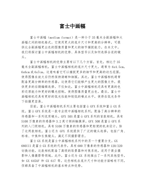
富士中画幅富士中画幅(medium format)是一种介于35毫米全副画幅和大画幅之间的相机格式。
它使用更大的底片尺寸和更高的分辨率,可提供比全副画幅更出色的图像质量和更大的细节捕捉能力。
在本文中,我们将探讨富士中画幅相机的优势、具体型号以及如何选择合适的镜头。
富士中画幅相机的优势主要有以下几个方面。
首先,相比于35毫米全副画幅相机,富士中画幅相机的底片尺寸更大,通常为6x4.5cm,6x6cm或6x7cm。
这意味着它可以捕捉更多的细节和更高的动态范围,使得图像在放大后仍然保持清晰和细腻。
其次,富士中画幅相机通常配备更高分辨率的传感器,这使得它们能够产生更大的图像文件,提供更多的后期编辑选择。
不仅如此,富士中画幅相机还具有更高的色彩还原能力和更好的曝光控制,使得图像质量更出色。
最后,富士中画幅相机还具有更好的低光性能和较低的噪点水平,使得在低光条件下拍摄更容易。
目前,富士中画幅相机系列主要包括富士GFX系统和富士GX系统。
富士GFX系统是一款专业级中画幅相机系列,配备了高分辨率的传感器和一系列优质镜头。
GFX 50S是富士GFX系列的首款相机,具有5100万像素的传感器和3.2英寸倾斜触摸屏。
GFX 50R是富士GFX系列的入门级相机,具有5100万像素的传感器和更轻便的机身设计。
除了这两款相机,富士还为GFX系统提供了广泛的镜头选择,包括广角、标准、中焦和长焦镜头,满足不同摄影需求。
富士GX系统是富士中画幅相机系列中的另一个重要分支。
GX680III是富士GX系统的代表作,具有680万像素的传感器和120/220切换功能。
这款相机配备了高级的取景器和对焦系统,适用于商业摄影和人像摄影等领域。
此外,富士还为GX系统推出了一系列其他型号,如GX 645AF和GX 617等。
这些相机在底片尺寸和功能方面略有不同,但都具备了中画幅相机的基本特点和优势。
在选择适合的富士中画幅镜头时,我们需要考虑几个因素。
OSB reference WW
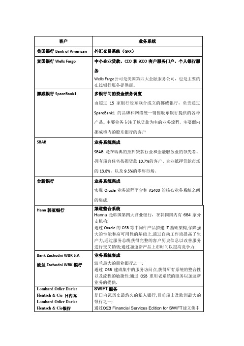
BankZachodniWBK S.A
波兰ZachodniWBK银行
业务系统集成
波兰最大的商业银行之一;
ZFS苏黎世金融服务集团
应用集成平台
ZFS是全球十大金融保险集团之一;
通过部署OSB等中间件,构建了企业级统一的基于SOA的集成架构,集成了包括IBMFileNet、IBM MQ、MainFrame以及第三方外部系统在内的异构系统。并通过服务治理,统一和标准化了对这些异构系统的访问的管理。进一步,通过Oracle BPM业务流程管理平台,构造了苏黎世内部跨系统的文档流程管理系统。
通过OSBFinancial Services Edition for SWIFT建立集中的遵循SWIFT的银行间数据交换平台。这使得它能更快的给客户提供更具竞争力和革新力的遵循标准的银行间服务。
City of Chicago
业务系统集成
美国区域银行;
整合平台集成了EPR,CRM ,帐务,金融以及数据仓库等系统,实现了各部门间数据实时共享。提高了业务处理效率。
First Franklin
应用整合平台
整合平台建成基于SOA的基础架构,加速了新产品的面世,降低了开销和风险。
NAB澳大利亚国民银行
共享服务中心
NAB是澳大利亚大型金融服务机构;
通过OSB等中间件建成共享服务中心,支持异构异地系统间共享数据和服务;实现了传统渠道到现代渠道的转变,以及跨国收购后业务整合要求。
SBAB
业务系统集成
gfx_3.1_font_cn
字体和文字配置本文件描述了Scaleform GFx 3.1中使用的字体和文本渲染系统,详细介绍了如何对素材资源和GFx C++ APIs进行国际化配置。
作者:Maxim Shemanarev, Michael Antonov版本: 1.05最后编辑:2009年5月7日保密版权所有 © 2009Scaleform 公司及其授权商。
未经Scaleform公司的书面许可,不得通过任何电子或机械手段对本文件进行任何形式的复制或传播,包括影印、录音、或信息存储及信息检索系统。
Scaleform、Scaleform 标识、GFC、 GFx以及GFx 标识都是Scaleform 公司注册的商标。
所有其他商标和注册商标都是属于其各自所有者的财产。
Scaleform的联系方式:文件名Scaleform GFx 3.1字体和文字配置概述地址Scaleform Corporation6305 Ivy Lane, Suite 310Greenbelt, MD 20770, USA网站电子邮件info@直接呼叫(301) 446-3200传真(301) 446-3199目录1引言:GFx中的字体 (1)1.1Flash文本和字体概要 (1)1.1.1文本域 (2)1.1.2字符嵌入 (3)1.1.3嵌入字体内存占用 (4)1.1.4控制字体内存占用 (4)1.2游戏用户界面的字体决策 (5)2第1部分:创建游戏字体库 (7)2.1字体符号 (7)2.1.1导出和导入字体符号 (8)2.1.2导出字体和字符嵌入 (9)2.2创建 gfxfontlib.swf文件步骤 (9)3第2部分:选择国际化方法 (11)3.1导入替代字体 (11)3.1.1国际文本的配置 (13)3.1.2GFxPlayer中的国际化 (14)3.2设备字体仿真 (15)3.3自定义资源生成 (16)4第3部分:设定字体资源 (17)4.1字体查找的顺序 (17)4.2GFxFontMap (18)4.3GFxFontLib (19)4.4GFxFontProviderWin32 (20)4.4.1使用自动提示文本 (20)4.4.2设定自动提示 (22)4.5GFxFontProviderFT2 (22)4.5.1将FreeType字体映射入文件 (23)4.5.2将字体映射到内存 (24)5第4部分:配置字体渲染 (26)5.1字体缓存管理器 (26)5.2利用动态字体缓存 (28)5.3预处理字体纹理- gfxexport (30)5.4设定字体字型填充程序 (32)5.5矢量控制 (33)6第5部分:文本过滤效果和动作脚本扩展 (35)6.1过滤器类型,可用选项和限制 (35)6.2过滤品质 (36)6.3动态过滤 (37)6.4GFx的动作脚本扩展 (37)1引言:GFx中的字体Scaleform GFx 3.x/2.x载有一个新的灵活的字体系统,它可以提供高品质的HTML格式的可转换文本。
gfx_4.0_scale9grid_cn
目录1 Βιβλιοθήκη 3 4 介绍: 在 Flash 和 GFx 中使用 Scale9Grid.............................................................................. 1 转换........................................................................................................................................... 2 处理位图 ................................................................................................................................... 2 交互式窗口 ................................................................................................................................ 5 4.1 4.2 Flash 兼容的例子 ................................................................................................................ 5 高级的 GFx 举例 ................................................................................................................. 9
BS EN ISO 8434-1-2007

Februar 2008DEUTSCHE NORMNormenausschuss Rohrleitungen und Dampfkesselanlagen (NARD) im DINNormenausschuss Maschinenbau (NAM) im DINPreisgruppe 20DIN Deutsches Institut für Normung e.V. · Jede Art der Vervielfältigung, auch auszugsweise, nur mit Genehmigung des DIN Deutsches Institut für Normung e.V., Berlin, gestattet.ICS 23.100.40!,x7D"9852033www.din.de DDIN EN ISO 8434-1Metallische Rohrverschraubungen für Fluidtechnik und allgemeine Anwendung –Teil 1: Verschraubungen mit 24°-Konus (ISO 8434-1:2007);Deutsche Fassung EN ISO 8434-1:2007Metallic tube connections for fluid power and general use –Part 1: 24 degree cone connectors (ISO 8434-1:2007);German version EN ISO 8434-1:2007Raccordements de tubes métalliques pour transmissions hydrauliques et pneumatiques et applications générales –Partie 1: Raccords coniques à 24 degrés (ISO 8434-1:2007);Version allemande EN ISO 8434-1:2007©Alleinverkauf der Normen durch Beuth Verlag GmbH, 10772 BerlinErsatz fürDIN EN ISO 8434-1:1997-11www.beuth.deGesamtumfang 54 SeitenA &I -N o r m e n a b o n n e m e n t - J u n g h e i n r i c h A G - K d .-N r .6004049 - A b o -N r .00852063/002/002 - 2008-01-24 09:38:51DIN EN ISO 8434-1:2008-022Nationales VorwortDieses Dokument (EN ISO 8434-1:2007) wurde vom Technischen Komitee ISO/TC 131 …Fluid Power Systems“ in Zusammenarbeit mit dem Technischen Komitee ECISS/TC 29 …Stahlrohre und Fittings für Stahl-rohre“ erarbeitet, dessen Sekretariat vom UNI (Italien) gehalten wird.Für die deutsche Mitarbeit ist der Arbeitsausschuss NA 082-00-07 AA …Rohrverschraubungen" im Normen-ausschuss Rohrleitungen und Dampfkesselanlagen (NARD) verantwortlich.Für die in Abschnitt 2 zitierten Internationalen Normen wird im Folgenden auf die entsprechende Deutsche Norm hingewiesen: ISO 48 siehe DIN ISO 48ISO 5598 siehe E DIN ISO 5598 ISO 6149-1 siehe DIN ISO 6149-1 ISO 6149-2 siehe DIN ISO 6149-2 ISO 6149-3 siehe DIN ISO 6149-3 ISO 9974-1 siehe DIN EN ISO 9974-1 ISO 9974-2 siehe DIN EN ISO 9974-2 ISO 9974-3 siehe DIN EN ISO 9974-3 ISO 12151-2 siehe DIN ISO 12151-2 ISO 19879 siehe DIN EN ISO 19879ÄnderungenGegenüber DIN EN ISO 8434-1:1997-11 wurden folgende Änderungen vorgenommen:a) Das umfangreiche nationale Vorwort der ersten Ausgabe von DIN EN ISO 8434-1 wurde gestrichen.Hintergrund ist die Tatsache, dass die Anwendung der deutschen Fassung zur Bestellung von Teilen führen konnte, die der Anwender bzw. Hersteller in der ISO 8434-1 nicht identifizieren konnte. b) Hinsichtlich der Prüfverfahren wurde die neue Prüfnorm ISO 19879 herangezogen. c) Die Abbildungen wurden teilweise überarbeitet, bzw. neu erstellt.d) Die Normativen Verweisungen wurden aktualisiert. Frühere AusgabenDIN 3853: 1958-09, 1963-06, 1982-11 DIN 3861: 1957-09, 1982-11, 1994-05 DIN 3865: 1985-02, 1994-05DIN 3870: 1954-11, 1957-05, 1961-08, 1965-09, 1983-01, 1985-05 DIN 3901: 1957-06, 1965-02, 1984-04, 1987-09 DIN 3902: 1957-06, 1984-04DIN 3905: 1957-06, 1965-12, 1984-04 DIN 3908: 1957-06, 1965-12, 1984-04 DIN 3909: 1957-06, 1965-12, 1984-04 DIN 3910: 1958-03, 1965-02, 1984-04 DIN 3911: 1957-06, 1965-12, 1984-04 DIN 3912: 1957-06, 1965-12, 1984-04 DIN 3951: 1966-08, 1984-04 DIN 3952: 1969-09, 1984-04 DIN 3953: 1969-09, 1984-04 DIN 3954: 1969-09, 1984-04 DIN 3955: 1984-04, 1987-09 DIN EN ISO 8434-1: 1997-11A &I -N o r m e n a b o n n e m e n t - J u n g h e i n r i c h A G - K d .-N r .6004049 - A b o -N r .00852063/002/002 - 2008-01-24 09:38:51DIN EN ISO 8434-1:2008-023Nationaler Anhang NA(informativ)LiteraturhinweiseDIN EN ISO 9974-1, Leitungsanschlüsse für Fluidtechnik und allgemeine Anwendung — Einschraublöcher und Einschraubzapfen mit Gewinde nach ISO 261 und Elastomerdichtung oder metallener Dichtkante — Teil 1: EinschraublöcherDIN EN ISO 9974-2, Leitungsanschlüsse für Fluidtechnik und allgemeine Anwendung — Einschraublöcher und Einschraubzapfen mit Gewinde nach ISO 261 und Elastomerdichtung oder metallener Dichtkante — Teil 2: Einschraubzapfen mit Elastomerdichtung (Typ E)DIN EN ISO 9974-3, Leitungsanschlüsse für Fluidtechnik und allgemeine Anwendung — Einschraublöcher und Einschraubzapfen mit Gewinde nach ISO 261 und Elastomerdichtung oder metallener Dichtkante — Teil 3: Einschraubzapfen mit metallener Dichtkante (Typ B)DIN EN ISO 19879, Metallische Rohrverbindungen für Fluidtechnik und allgemeine Anwendung — Prüf-verfahren für hydraulische Rohrverbindungen in der Fluidtechnik E DIN ISO 5598, Fluidtechnik — VokabularDIN ISO 6149-1, Leitungsanschlüsse für Fluidtechnik und allgemeine Anwendung — Einschraublöcher und Einschraubzapfen mit Gewinde nach ISO 261 und O-Ring-Abdichtung — Teil 1: Einschraublöcher mit Ansenkung für O-Ring- AbdichtungDIN ISO 6149-2, Leitungsanschlüsse für Fluidtechnik und allgemeine Anwendung — Einschraublöcher und Einschraubzapfen mit Gewinde nach ISO 261 und O-Ring-Abdichtung — Teil 2: Einschraubzapfen, schwere Reihe (S-Reihe); Maße, Konstruktion, Prüfverfahren und AnforderungenDIN ISO 6149-3, Leitungsanschlüsse für Fluidtechnik und allgemeine Anwendung — Einschraublöcher und Einschraubzapfen mit Gewinde nach ISO 261 und O-Ring-Abdichtung — Teil 3: Einschraubzapfen, leichte Reihe (L-Reihe); Maße, Konstruktion, Prüfverfahren und AnforderungenDIN ISO 48, Elastomere und thermoplastische Elastomere — Bestimmung der Härte (Härte zwischen 10 IRHD und 100 IRHD)DIN ISO 12151-2, Leitungsanschlüsse für Fluidtechnik und allgemeine Anwendungen — Schlaucharma- turen — Teil 2: Schlaucharmaturen mit 24°-Dichtkegel und O-Ring nach ISO 8434-1 und ISO 8434-4A &I -N o r m e n a b o n n e m e n t - J u n g h e i n r i c h A G - K d .-N r .6004049 - A b o -N r .00852063/002/002 - 2008-01-24 09:38:51DIN EN ISO 8434-1:2008-024— Leerseite —A &I -N o r m e n a b o n n e m e n t - J u n g h e i n r i c h A G - K d .-N r .6004049 - A b o -N r .00852063/002/002 - 2008-01-24 09:38:51EUROPÄISCHE NORM EUROPEAN STANDARD NORME EUROPÉENNEEN ISO 8434-1September 2007ICS 23.100.40Ersatz für EN ISO 8434-1:1997Deutsche FassungMetallische Rohrverschraubungen für Fluidtechnik undallgemeine Anwendung —Teil 1: Verschraubungen mit 24˚-Konus(ISO 8434-1:2007)Metallic tube connections for fluid power and general use —Part 1: 24˚ cone connectors(ISO 8434-1:2007)Raccordements de tubes métalliques pour transmissions hydrauliques et pneumatiques et applications générales —Partie 1: Raccords coniques à 24˚(ISO 8434-1:2007)Diese Europäische Norm wurde vom CEN am 11. August 2007 angenommen.Die CEN-Mitglieder sind gehalten, die CEN/CENELEC-Geschäftsordnung zu erfüllen, in der die Bedingungen festgelegt sind, unter denen dieser Europäischen Norm ohne jede Änderung der Status einer nationalen Norm zu geben ist. Auf dem letzten Stand befindliche Listen dieser nationalen Normen mit ihren bibliographischen Angaben sind beim Management-Zentrum des CEN oder bei jedem CEN-Mitglied auf Anfrage erhältlich.Diese Europäische Norm besteht in drei offiziellen Fassungen (Deutsch, Englisch, Französisch). Eine Fassung in einer anderen Sprache, die von einem CEN-Mitglied in eigener Verantwortung durch Übersetzung in seine Landessprache gemacht und dem Management-Zentrum mitgeteilt worden ist, hat den gleichen Status wie die offiziellen Fassungen.CEN-Mitglieder sind die nationalen Normungsinstitute von Belgien, Bulgarien, Dänemark, Deutschland, Estland, Finnland, Frankreich, Griechenland, Irland, Island, Italien, Lettland, Litauen, Luxemburg, Malta, den Niederlanden, Norwegen, Österreich, Polen, Portugal,Rumänien, Schweden, der Schweiz, der Slowakei, Slowenien, Spanien, der Tschechischen Republik, Ungarn, dem Vereinigten Königreich und Zypern.EUR OP ÄIS C HES KOM ITEE FÜR NOR M UNG EUROPEAN COMMITTEE FOR STANDARDIZATION C O M I T É E U R O P ÉE N D E N O R M A LI S A T I O NManagement-Zentrum: rue de Stassart, 36 B- 1050 Brüssel© 2007 CENAlle Rechte der Verwertung, gleich in welcher Form und in welchemVerfahren, sind weltweit den nationalen Mitgliedern von CEN vorbehalten.Ref. Nr. EN ISO 8434-1:2007 DA &I -N o r m e n a b o n n e m e n t - J u n g h e i n r i c h A G - K d .-N r .6004049 - A b o -N r .00852063/002/002 - 2008-01-24 09:38:51DIN EN ISO 8434-1:2008-02 EN ISO 8434-1:2007 (D)2InhaltSeiteVorwort ................................................................................................................................................................3 Einleitung.............................................................................................................................................................4 1 Anwendungsbereich .............................................................................................................................5 2 Normative Verweisungen......................................................................................................................5 3 Begriffe ...................................................................................................................................................6 4 Werkstoffe ..............................................................................................................................................7 4.1 Allgemeines............................................................................................................................................7 4.2 Anschlussstutzen..................................................................................................................................8 4.3 Überwurfmuttern....................................................................................................................................8 4.4 Schneidringe..........................................................................................................................................8 4.5 O-Ringe...................................................................................................................................................9 5 Druck-/Temperatur-Anforderungen .....................................................................................................9 6 Bezeichnung von Rohrverschraubungen.........................................................................................13 7 Anforderungen an Rohre....................................................................................................................16 8 Schlüsselweiten und Grenzabmaße..................................................................................................16 9 Ausführung...........................................................................................................................................16 9.1 Rohrverschraubungen........................................................................................................................16 9.2 Maße......................................................................................................................................................16 9.3 Grenzabmaße für den Durchgang......................................................................................................17 9.4 Grenzabmaße für Winkel.....................................................................................................................17 9.5 Einzelheiten der Gestaltung ...............................................................................................................17 9.6 Einschraublöcher und Einschraubzapfen.........................................................................................17 9.7Abdichtung des Einschraubzapfens..................................................................................................17 10 Gewinde................................................................................................................................................17 10.1 Verschraubung Rohrseite...................................................................................................................17 10.2 Verschraubung Einschraubzapfen....................................................................................................17 11 Herstellung...........................................................................................................................................18 11.1 Konstruktion.........................................................................................................................................18 11.2 Ausführung...........................................................................................................................................18 11.3 Oberflächenbehandlung .....................................................................................................................18 11.4 Kanten...................................................................................................................................................18 12 Montageanleitungen............................................................................................................................18 13 Bestellangaben ....................................................................................................................................19 14 Kennzeichnung von Bauteilen ...........................................................................................................19 15 Prüfung der Funktionsfähigkeit und Eignung..................................................................................19 15.1 Allgemeines..........................................................................................................................................19 15.2 Wiederholmontage-Prüfung ...............................................................................................................19 15.3 Druckprüfung.......................................................................................................................................19 15.4 Berstprüfung........................................................................................................................................19 15.5 Druckimpulsprüfung ...........................................................................................................................20 15.6 Schwingungsprüfung..........................................................................................................................20 15.7 Dichtheitsprüfung (mit Gas)...............................................................................................................20 15.8 Überanzug-Prüfung.............................................................................................................................20 16Angaben der Kennzeichnung (Verweisung auf diesen Teil der ISO 8434) (21)Literaturhinweise (50)A &I -N o r m e n a b o n n e m e n t - J u n g h e i n r i c h A G - K d .-N r .6004049 - A b o -N r .00852063/002/002 - 2008-01-24 09:38:51DIN EN ISO 8434-1:2008-02EN ISO 8434-1:2007 (D)3VorwortDieses Dokument (EN ISO 8434-1:2007) wurde vom Technischen Komitee ISO/TC 131 …Fluid Power Systems“ in Zusammenarbeit mit dem Technischen Komitee CEN/TC ECISS/TC 29 …Stahlrohre und Fittings für Stahlrohre“ erarbeitet, dessen Sekretariat vom UNI gehalten wird.Diese Europäische Norm muss den Status einer nationalen Norm erhalten, entweder durch Veröffentlichung eines identischen Textes oder durch Anerkennung bis März 2008 und etwaige entgegenstehende nationale Normen müssen bis März 2008 zurückgezogen werden. Dieses Dokument ersetzt EN ISO 8434-1:1997.Entsprechend der CEN/CENELEC-Geschäftsordnung sind die nationalen Normungsinstitute der folgenden Länder gehalten, diese Europäische Norm zu übernehmen: Belgien, Bulgarien, Dänemark, Deutschland, Estland, Finnland, Frankreich, Griechenland, Irland, Island, Italien, Lettland, Litauen, Luxemburg, Malta, Niederlande, Norwegen, Österreich, Polen, Portugal, Rumänien, Schweden, Schweiz, Slowakei, Slowenien, Spanien, Tschechische Republik, Ungarn, Vereinigtes Königreich und Zypern.AnerkennungsnotizDer Text von ISO 8434-1:2007 wurde vom CEN als EN ISO 8434-1:2007 ohne irgendeine Abänderung genehmigt.A &I -N o r m e n a b o n n e m e n t - J u n g h e i n r i c h A G - K d .-N r .6004049 - A b o -N r .00852063/002/002 - 2008-01-24 09:38:51DIN EN ISO 8434-1:2008-02 EN ISO 8434-1:2007 (D)4EinleitungIn fluidtechnischen Anlagen wird Energie durch ein mit Druck beaufschlagtes Fluid (Flüssigkeit oder Gas) innerhalb eines geschlossenen Kreislaufs übertragen, geregelt und gesteuert. In allgemeinen Anwendungs-fällen kann ein Fluid unter Anwendung von Druck transportiert werden.Bauteile können durch ihre Einschraublöcher mittels Anschlussteilen (Verschraubungen) an Rohre oder an Rohre und Schläuche angeschlossen werden. Rohre sind starre Leitungen, Schläuche sind flexible Leitungen.A &I -N o r m e n a b o n n e m e n t - J u n g h e i n r i c h A G - K d .-N r .6004049 - A b o -N r .00852063/002/002 - 2008-01-24 09:38:51DIN EN ISO 8434-1:2008-02EN ISO 8434-1:2007 (D)51 AnwendungsbereichDieser Teil der ISO 8434 legt allgemeine und maßliche Anforderungen an 24°-Rohrverschraubungen mit Schneidring und O-Ring-Dichtkegel (kurz als DKO bezeichnet) fest, die für die Verwendung mit Stahlrohren und Rohren aus Nichteisenmetallen mit einem Außendurchmesser von 4 mm bis einschließlich 42 mm ge-eignet sind. Diese Rohrverschraubungen sind für die Fluidtechnik und allgemeine Anwendungen in dem in diesem Teil der ISO 8434 festgelegten Temperatur- und Druckbereich vorgesehen.Sie sind für die Verbindung von Rohren mit geraden Enden und Schlaucharmaturen an Einschraublöchern nach ISO 6149-1, ISO 1179-1 und ISO 9974-1 vorgesehen. (Festlegungen für Schlaucharmaturen, siehe ISO 12151-2).Diese Rohrverschraubungen sorgen in Hydraulikanlagen mit Arbeitsdrücken nach Tabelle 1 für Verbindungen mit vollem Durchfluss. Da der Druck, bei dem eine Anlage zufriedenstellend funktionsfähig ist, durch viele Faktoren beeinflusst wird, sind diese Werte nicht als abgesicherte Mindestwerte zu betrachten. Für jeden Anwendungsfall müssen ausreichend Prüfungen durchgeführt werden, die sowohl vom Anwender als auch vom Hersteller zu bewerten sind, um sicherzustellen, dass die geforderten Leistungsstufen eingehalten werden.ANMERKUNG 1 Für Neukonstruktionen in hydraulischen Anlagen der Fluidtechnik gelten die Anforderungen in 9.6. Sofern nach den Anforderungen für den jeweiligen Anwendungsfall die Verwendung von Elastomerdichtungen zulässig ist, werden für die Rohrverschraubung Ausführungen nach Internationalen Normen mit Elastomerdichtungen bevorzugt. ANMERKUNG 2 Für Anwendungsfälle außerhalb des in dieser Norm festgelegten Druck- und/oder Temperaturbereichs, siehe 5.4.Dieser Teil der ISO 8434 legt ferner eine Prüfung der Funktionsfähigkeit und Eignung dieser Rohr-verschraubungen fest.2 Normative VerweisungenDie folgenden zitierten Dokumente sind für die Anwendung dieses Dokuments erforderlich. Bei datierten Verweisungen gilt nur die in Bezug genommene Ausgabe. Bei undatierten Verweisungen gilt die letzte Ausgabe des in Bezug genommenen Dokuments (einschließlich aller Änderungen).ISO 48, Rubber, vulcanized or thermoplastic — Determination of hardness (hardness between 10 IRHD and 100 IRHD)ISO 228-1:2000, Pipe threads where pressure-tight joints are not made on the threads — Part 1: Dimensions, tolerances and designationISO 261, ISO general-purpose metric screw threads — General planISO 965-1:1998, ISO general-purpose metric screw threads — Tolerances — Part 1: Principles and basic dataISO 1127, Stainless steel tubes — Dimensions, tolerances and conventional masses per unit lengthISO 1179-1, Connections for general use and fluid power — Ports and stud ends with ISO 228-1 threads with elastomeric or metal-to-metal sealing — Part 1: Threaded portsISO 1179-2, Connections for general use and fluid power — Ports and stud ends with ISO 228-1 threads with elastomeric or metal-to-metal sealing — Part 2: Heavy-duty (S series) and light-duty (L series) stud ends with elastomeric sealing (type E)A &I -N o r m e n a b o n n e m e n t - J u n g h e i n r i c h A G - K d .-N r .6004049 - A b o -N r .00852063/002/002 - 2008-01-24 09:38:51DIN EN ISO 8434-1:2008-02 EN ISO 8434-1:2007 (D)6ISO 1179-4, Connections for general use and fluid power — Ports and stud ends with ISO 228-1 threads with elastomeric or metal-to-metal sealing — Part 4: Stud ends for general use only with metal-to-metal sealing (type B)ISO 3304, Plain end seamless precision steel tubes — Technical conditions for delivery ISO 3305, Plain end welded precision steel tubes — Technical conditions for deliveryISO 3601-3:2005, Fluid systems — Sealing devices — O-rings — Part 3: Quality acceptance criteria ISO 4759-1, Tolerances for fasteners — Part 1: Bolts, screws, studs and nuts — Product grades A, B and C ISO 5598:1985, Fluid power systems and components — VocabularyISO 6149-1, Connections for fluid power and general use — Ports and stud ends with ISO 261 threads and O-ring sealing — Part 1: Ports with O-ring seal in truncated housingISO 6149-2, Connections for fluid power and general use — Ports and stud ends with ISO 261 threads and O-ring sealing — Part 2: Heavy-duty (S series) stud ends — Dimensions, design, test methods and require-mentsISO 6149-3, Connections for fluid power and general use — Ports and stud ends with ISO 261 threads and O-ring sealing — Part 3: Light-duty (L series) stud ends — Dimensions, design, test methods and require-mentsISO 9227, Corrosion tests in artificial atmospheres — Salt spray testsISO 9974-1, Connections for general use and fluid power — Ports and stud ends with ISO 261 threads with elastomeric or metal-to-metal sealing — Part 1: Threaded portsISO 9974-2, Connections for general use and fluid power — Ports and stud ends with ISO 261 threads with elastomeric or metal-to-metal sealing — Part 2: Stud ends with elastomeric sealing (type E)ISO 9974-3, Connections for general use and fluid power — Ports and stud ends with ISO 261 threads with elastomeric or metal-to-metal sealing — Part 3: Stud ends with metal-to-metal sealing (type B)ISO 12151-2, Connections for hydraulic fluid power and general use — Hose fittings — Part 2: Hose fittings with ISO 8434-1 and 8434-4 24° cone connector ends with O-ringsISO 19879:2005, Metallic tube connections for fluid power and general use — Test methods for hydraulic fluid power connections3 BegriffeFür die Anwendung dieses Dokumentes gelten die Begriffe nach ISO 5558 sowie die folgenden Begriffe. 3.1Anschlussstück Verschraubunglecksicheres Teil, mit dem Rohrleitungen (Leitungsteile) miteinander oder mit Geräten verbunden werdenANMERKUNGIn Anlehnung an ISO 5598:1985, Begriff 5.2.2.3.2BefestigungsgewindeAnschlussgewinde einer vollständigen VerschraubungA &I -N o r m e n a b o n n e m e n t - J u n g h e i n r i c h A G - K d .-N r .6004049 - A b o -N r .00852063/002/002 - 2008-01-24 09:38:51DIN EN ISO 8434-1:2008-02EN ISO 8434-1:2007 (D)73.3Durchgangzwei axial ausgerichtete Hauptabgänge eines T-Verbindungsstutzens oder eines Kreuz-Verbindungsstutzens 3.4Abzweigseitlicher Abgang oder Abgänge eines T-Verbindungsstutzens oder eines Kreuz-Verbindungsstutzens3.5AnfasenAnbringen eines Konus am Anfang eines Gewindes zur Erleichterung der Montage und zum Schutz des Gewindeanfangs vor Beschädigung3.6Baulänge FTF (Durchgang)Abstand zwischen zwei parallelen Stirnflächen von auf einer Achse liegenden Verschraubungsanschlüssen 3.7Baulänge FTC (Abzweig)Abstand zwischen der Stirnfläche eines Abgangs und der im Winkel angeordneten Mittelachse des Abgangs 3.8Montage-Drehmomentfür eine zufriedenstellende Montage erforderliches Drehmoment3.9maximaler Arbeitsdruckhöchster Druck, bei dem der Betrieb der Anlage oder Teilanlage unter stationären Bedingungen vorgesehen ist4 Werkstoffe4.1 AllgemeinesDie Bilder 1 und 2 zeigen die Querschnitte und Einzelteile von typischen 24°-Rohrverschraubungen.Legende1 Stutzen2 Überwurfmutter3 SchneidringBild 1 — Querschnitt einer typischen Rohrverschraubung mit 24° Konusanschluss und SchneidringA &I -N o r m e n a b o n n e m e n t - J u n g h e i n r i c h A G - K d .-N r .6004049 - A b o -N r .00852063/002/002 - 2008-01-24 09:38:51DIN EN ISO 8434-1:2008-02 EN ISO 8434-1:2007 (D)8Legende1 Stutzen2 Überwurfmutter3 DKO-Seite (einschließlich O-Ring)Bild 2 — Querschnitt einer typischen Rohrverschraubung mit 24° Konusanschluss und Dichtkegel mitO-Ring (DKO)4.2 AnschlussstutzenStutzen müssen aus unlegiertem Stahl hergestellt sein, der die Mindestanforderungen der in Abschnitt 5 fest-gelegten Druck/Temperatur-Anforderungen erfüllt. Sie müssen für das zu befördernde Fluid geeignet sein und eine wirksame Verbindung erzielen. Stutzen für Schweißverschraubungen und Schweißkegel müssen aus Werkstoffen hergestellt sein, die als schweißgeeignet gelten.Für Stutzen aus nichtrostendem Stahl oder Kupferlegierungen müssen die Druck-/Temperatur-Zuordnungen vom Hersteller festgelegt werden.4.3 ÜberwurfmutternÜberwurfmuttern, die mit Stutzen aus unlegiertem Stahl verwendet werden, müssen aus unlegiertem Stahl hergestellt sein. Überwurfmuttern für Stutzen aus nichtrostendem Stahl müssen ebenfalls aus nichtrostendem Stahl sein, sofern nichts anderes festgelegt ist. Überwurfmuttern, die mit Stutzen aus Kupferlegierung verwendet werden, müssen aus einem ähnlichen Werkstoff wie der Stutzen hergestellt sein.4.4 Schneidringe4.4.1 Der Schneidringwerkstoff muss für das zu befördernde Fluid geeignet sein und eine wirksame Verbindung erzielen.4.4.2 Schneidringe aus Stahl müssen in Kombination mit anderen Verschraubungsteilen aus Stahl und Rohren aus Stahl verwendet werden.4.4.3 Schneidringe aus nichtrostendem Stahl müssen in Kombination mit anderen Verschraubungsteilen aus nichtrostendem Stahl und Rohren aus nichtrostendem Stahl verwendet werden.4.4.4 Schneidringe aus Messing müssen in Kombination mit anderen Verschraubungsteilen aus Messing und Rohren aus Kupfer verwendet werden. 4.4.5Andere Werkstoffkombinationen sind zwischen Besteller und Lieferer zu vereinbaren.A &I -N o r m e n a b o n n e m e n t - J u n g h e i n r i c h A G - K d .-N r .6004049 - A b o -N r .00852063/002/002 - 2008-01-24 09:38:51DIN EN ISO 8434-1:2008-02EN ISO 8434-1:2007 (D)94.5 O-RingeSofern nichts anderes festgelegt ist, müssen für die Verwendung mit Druckflüssigkeiten auf Erdölbasis nach den in Abschnitt 5 und Tabelle 1 festgelegten Druck-/Temperatur-Anforderungen O-Ringe für Verschrau-bungen nach diesem Teil der ISO 8434 aus NBR (Nitrilbutadienkautschuk) mit einer Härte von (90 ± 5) IRHD, gemessen nach ISO 48, mit den in Tabelle 5 angegebenen Maßen verwendet werden, die mindestens den Kriterien der Güteabnahme nach ISO 3601-3:2005, Gütestufe N, entsprechen. In Fällen, in denen die Druck-/ Temperaturanforderungen dieses Teils der ISO 8434 und/oder die in der Anlage verwendete Druckflüssigkeit von den Festlegungen in Abschnitt 5 und Tabelle 1 abweichen, ist mit dem Hersteller der Verschraubung Rücksprache zu halten, um sicherzustellen, dass ein geeigneter Werkstoff für den O-Ring gewählt wird.5 Druck-/Temperatur-Anforderungen5.1 Rohrverschraubungen aus unlegiertem Stahl nach diesem Teil der ISO 8434 müssen bei Verwendung mit Druckflüssigkeiten auf Erdölbasis bei Temperaturen zwischen −40 °C und +120 °C ohne Leckage mindestens den in den Tabellen 1 bis 3 angegebenen Arbeitsdrücken ab einem Unterdruck von 6,5 kPa (0,065 bar) Absolutdruck standhalten.5.2 Rohrverschraubungen nach diesem Teil der ISO 8434 dürfen Dichtungen aus Elastomeren enthalten. Sofern nicht anders festgelegt, werden Rohrverschraubungen mit Elastomerteilen für den definierten Arbeits-temperaturbereich für Druckflüssigkeiten auf Erdölbasis hergestellt und geliefert. Die Verschraubungen können für die Anwendung mit anderen Fluiden einen reduzierten Arbeitstemperaturbereich haben oder völlig ungeeignet sein. Die Hersteller dürfen auf Anfrage Rohrverschraubungen mit geeigneten Elastomer-dichtungen liefern, die den Anforderungen an den Arbeitstemperaturbereich bei Verwendung mit unterschied-lichen Druckflüssigkeiten entsprechen.5.3 Die Verschraubung muss mindestens alle in Abschnitt 15 festgelegten Anforderungen erfüllen. Die Prüfung ist bei Umgebungstemperatur durchzuführen.5.4 Für Anwendungsfälle unter Bedingungen, die außerhalb der in den Tabellen 1 bis 3 sowie in 5.1 und 5.3 angegebenen Grenzwerten für Druck und/oder Temperatur liegen, ist der Hersteller zu befragen.5.5 Je nach Anwendungsfall und Druck-Stufe gibt es 3 Baureihen von Rohrverschraubungen, die wie folgt benannt werden:LL: Sehr leichte Reihe L: Leichte Reihe S: Schwere ReiheBereiche für Rohr-Außendurchmesser und Druck sind in den Tabellen 1 bis 3 angegeben.A &I -N o r m e n a b o n n e m e n t - J u n g h e i n r i c h A G - K d .-N r .6004049 - A b o -N r .00852063/002/002 - 2008-01-24 09:38:51。
快乐男生张赫

快乐男声之8090组合队长张赫张赫,一直追求音乐梦想的俊美男孩,体现出作为新一代的年轻人精神。
张赫, 都是那颗最亮的星,一个用心去演绎的歌者,将以绝对的优势唱响整个宇宙……张赫,一个用心去抒写,用灵魂去歌唱的音乐奇才.张赫,一个怀揣音乐梦想的新时代歌手张赫,一个真诚从梦想中走来的男孩张赫, 无敌的唱工,完美的声线,动人的情歌,帅气内敛的外表,纯真的音乐梦想,一直就这样简单! 简单!简单!简单!喜欢你那磁性如天籁般的歌声, 欣赏你那随和而充满魅力的个性,赞叹你那为梦想执着而付出的勇气, 佩服你那种坚韧更坚定的淡泊的心境……你就是张赫内敛俊美小正太[1]姓名;张赫籍贯:辽宁英文名:ryan出生年月:1984年9月17日星座:处女座身高:184cm就读学校:沈阳音乐学院精通乐器:钢琴粉丝名称:赫顶红张赫的沈阳快男之旅400进50演唱曲目:《you got it bad》(原唱:usher)50进35演唱曲目:《you are beautiful》(原唱:James blunt)、《花田错》(原唱:王力宏)35进25演唱曲目:《爱爱爱》(原唱:方大同)25进20演唱曲目:《hero》(原唱:enrique iglesias)目前现任8090组合(快乐天团)团长张赫是一个优雅的大男孩,要求完美的处女座,弹得一手的好钢琴,为人善良可亲,大家要多多支持他哟!!!张赫,沈阳快男里的“白马王子”。
外型帅气,曾和超女张含韵合拍过MV<考试中>。
帅或许是张赫的一个标签,实力或许是张赫的另一个标签。
在25进20的晋级赛上,张赫PK掉型男李鹤、陈骁,情歌王子王梓豪。
成为首位晋级沈阳快男20强的选手,也是首位晋级全国300强的沈阳快男。
3GPP协议-36521-1-e40_s00-s05
3GPP TS 36.521-1 V14.4.0 (2017-09)Technical Specification3rd Generation Partnership Project; Technical Specification Group Radio Access Network; Evolved Universal Terrestrial Radio Access (E-UTRA);User Equipment (UE) conformance specification;Radio transmission and reception;Part 1: Conformance Testing(Release 14)The present document has been developed within the 3rd Generation Partnership Project (3GPP TM) and may be further elaborated for the purposes of 3GPP.KeywordsUMTS LTE3GPPPostal address3GPP support office address650 Route des Lucioles - Sophia AntipolisValbonne - FRANCETel.: +33 4 92 94 42 00 Fax: +33 4 93 65 47 16InternetCopyright NotificationNo part may be reproduced except as authorized by written permission.The copyright and the foregoing restriction extend to reproduction in all media.© 2017, 3GPP Organizational Partners (ARIB, ATIS, CCSA, ETSI, TSDSI, TTA, TTC).All rights reserved.UMTS™ is a Trade Mark of ETSI registered for the benefit of its members3GPP™ is a Trade Mark of ETSI registered for the benefit of its Members and of the 3GPP Organizational Partners LTE™ is a Trade Mark of ETSI registered for the benefit of its Members a nd of the 3GPP Organizational Partners GSM® and the GSM logo are registered and owned by the GSM AssociationContentsForeword (92)Introduction (92)1Scope (93)2References (94)3Definitions, symbols and abbreviations (96)3.1Definitions (96)3.2Symbols (98)3.3Abbreviations (100)4General (103)4.1Categorization of test requirements in CA, UL-MIMO, ProSe, Dual Connectivity, UE category 0, UEcategory M1, UE category 1bis, UE category NB1 and V2X Communication (104)4.2RF requirements in later releases (105)5Frequency bands and channel arrangement (106)5.1General (106)5.2Operating bands (106)5.2A Operating bands for CA (108)5.2B Operating bands for UL-MIMO (116)5.2C Operating bands for Dual Connectivity (116)5.2D Operating bands for ProSe (117)5.2E Operating bands for UE category 0 and UE category M1 (118)5.2F Operating bands for UE category NB1 (118)5.2G Operating bands for V2X Communication (118)5.3TX–RX frequency separation (119)5.3A TX–RX frequency separation for CA (120)5.4Channel arrangement (120)5.4.1Channel spacing (120)5.4.1A Channel spacing for CA (121)5.4.1F Channel spacing for UE category NB1 (121)5.4.2Channel bandwidth (121)5.4.2.1Channel bandwidths per operating band (122)5.4.2A Channel bandwidth for CA (124)5.4.2A.1Channel bandwidths per operating band for CA (126)5.4.2B Channel bandwidth for UL-MIMO (171)5.4.2B.1Channel bandwidths per operating band for UL- MIMO (171)5.4.2C Channel bandwidth for Dual Connectivity (171)5.4.2D Channel bandwidth for ProSe (171)5.4.2D.1Channel bandwidths per operating band for ProSe (171)5.4.2F Channel bandwidth for category NB1 (172)5.4.2G Channel bandwidth for V2X Communication (173)5.4.2G.1Channel bandwidths per operating band for V2X Communication (173)5.4.3Channel raster (174)5.4.3A Channel raster for CA (175)5.4.3F Channel raster for UE category NB1 (175)5.4.4Carrier frequency and EARFCN (175)5.4.4F Carrier frequency and EARFCN for category NB1 (177)6Transmitter Characteristics (179)6.1General (179)6.2Transmit power (180)6.2.1Void (180)6.2.2UE Maximum Output Power (180)6.2.2.1Test purpose (180)6.2.2.4Test description (182)6.2.2.4.1Initial condition (182)6.2.2.4.2Test procedure (183)6.2.2.4.3Message contents (183)6.2.2.5Test requirements (183)6.2.2_1Maximum Output Power for HPUE (185)6.2.2_1.1Test purpose (185)6.2.2_1.2Test applicability (185)6.2.2_1.3Minimum conformance requirements (185)6.2.2_1.4Test description (185)6.2.2_1.5Test requirements (186)6.2.2A UE Maximum Output Power for CA (187)6.2.2A.0Minimum conformance requirements (187)6.2.2A.1UE Maximum Output Power for CA (intra-band contiguous DL CA and UL CA) (189)6.2.2A.1.1Test purpose (189)6.2.2A.1.2Test applicability (189)6.2.2A.1.3Minimum conformance requirements (189)6.2.2A.1.4Test description (189)6.2.2A.1.5Test Requirements (191)6.2.2A.2UE Maximum Output Power for CA (inter-band DL CA and UL CA) (192)6.2.2A.2.1Test purpose (192)6.2.2A.2.2Test applicability (192)6.2.2A.2.3Minimum conformance requirements (192)6.2.2A.2.4Test description (192)6.2.2A.2.5Test Requirements (194)6.2.2A.3UE Maximum Output Power for CA (intra-band non-contiguous DL CA and UL CA) (196)6.2.2A.4.1UE Maximum Output Power for CA (intra-band contiguous 3DL CA and 3UL CA) (196)6.2.2A.4.1.1Test purpose (196)6.2.2A.4.1.2Test applicability (196)6.2.2A.4.1.3Minimum conformance requirements (196)6.2.2A.4.1.4Test description (196)6.2.2A.4.1.5Test Requirements (198)6.2.2A.4.2UE Maximum Output Power for CA (inter-band 3DL CA and 3UL CA) (198)6.2.2A.4.2.1Test purpose (199)6.2.2A.4.2.2Test applicability (199)6.2.2A.4.2.3Minimum conformance requirements (199)6.2.2A.4.2.4Test description (199)6.2.2A.4.2.5Test Requirements (201)6.2.2B UE Maximum Output Power for UL-MIMO (201)6.2.2B.1Test purpose (201)6.2.2B.2Test applicability (202)6.2.2B.3Minimum conformance requirements (202)6.2.2B.4Test description (204)6.2.2B.4.1Initial condition (204)6.2.2B.4.2Test procedure (205)6.2.2B.4.3Message contents (205)6.2.2B.5Test requirements (205)6.2.2B_1HPUE Maximum Output Power for UL-MIMO (207)6.2.2B_1.1Test purpose (207)6.2.2B_1.2Test applicability (207)6.2.2B_1.3Minimum conformance requirements (207)6.2.2B_1.4Test description (207)6.2.2B_1.5Test requirements (208)6.2.2C 2096.2.2D UE Maximum Output Power for ProSe (209)6.2.2D.0Minimum conformance requirements (209)6.2.2D.1UE Maximum Output Power for ProSe Discovery (209)6.2.2D.1.1Test purpose (209)6.2.2D.1.2Test applicability (209)6.2.2D.1.3Minimum Conformance requirements (209)6.2.2D.2UE Maximum Output Power for ProSe Direct Communication (211)6.2.2D.2.1Test purpose (211)6.2.2D.2.2Test applicability (211)6.2.2D.2.3Minimum conformance requirements (211)6.2.2D.2.4Test description (211)6.2.2E UE Maximum Output Power for UE category 0 (212)6.2.2E.1Test purpose (212)6.2.2E.2Test applicability (212)6.2.2E.3Minimum conformance requirements (212)6.2.2E.4Test description (212)6.2.2E.4.3Message contents (213)6.2.2E.5Test requirements (213)6.2.2EA UE Maximum Output Power for UE category M1 (215)6.2.2EA.1Test purpose (215)6.2.2EA.2Test applicability (215)6.2.2EA.3Minimum conformance requirements (215)6.2.2EA.4Test description (216)6.2.2EA.4.3Message contents (217)6.2.2EA.5Test requirements (217)6.2.2F UE Maximum Output Power for category NB1 (218)6.2.2F.1Test purpose (218)6.2.2F.2Test applicability (218)6.2.2F.3Minimum conformance requirements (218)6.2.2F.4Test description (219)6.2.2F.4.1Initial condition (219)6.2.2F.4.2Test procedure (220)6.2.2F.4.3Message contents (220)6.2.2F.5Test requirements (220)6.2.2G UE Maximum Output Power for V2X Communication (221)6.2.2G.1UE Maximum Output Power for V2X Communication / Non-concurrent with E-UTRA uplinktransmission (221)6.2.2G.1.1Test purpose (221)6.2.2G.1.2Test applicability (221)6.2.2G.1.3Minimum conformance requirements (221)6.2.2G.1.4Test description (222)6.2.2G.1.4.1Initial conditions (222)6.2.2G.1.4.2Test procedure (222)6.2.2G.1.4.3Message contents (222)6.2.2G.1.5Test requirements (223)6.2.2G.2UE Maximum Output Power for V2X Communication / Simultaneous E-UTRA V2X sidelinkand E-UTRA uplink transmission (223)6.2.2G.2.1Test purpose (223)6.2.2G.2.2Test applicability (223)6.2.2G.2.3Minimum conformance requirements (223)6.2.2G.2.4Test description (224)6.2.2G.2.4.1Initial conditions (224)6.2.2G.2.4.2Test procedure (225)6.2.2G.2.4.3Message contents (226)6.2.2G.2.5Test requirements (226)6.2.3Maximum Power Reduction (MPR) (226)6.2.3.1Test purpose (226)6.2.3.2Test applicability (226)6.2.3.3Minimum conformance requirements (227)6.2.3.4Test description (227)6.2.3.4.1Initial condition (227)6.2.3.4.2Test procedure (228)6.2.3.4.3Message contents (228)6.2.3.5Test requirements (229)6.2.3_1Maximum Power Reduction (MPR) for HPUE (231)6.2.3_1.1Test purpose (231)6.2.3_1.4Test description (232)6.2.3_1.5Test requirements (232)6.2.3_2Maximum Power Reduction (MPR) for Multi-Cluster PUSCH (232)6.2.3_2.1Test purpose (232)6.2.3_2.2Test applicability (232)6.2.3_2.3Minimum conformance requirements (233)6.2.3_2.4Test description (233)6.2.3_2.4.1Initial condition (233)6.2.3_2.4.2Test procedure (234)6.2.3_2.4.3Message contents (234)6.2.3_2.5Test requirements (234)6.2.3_3Maximum Power Reduction (MPR) for UL 64QAM (235)6.2.3_3.1Test purpose (236)6.2.3_3.2Test applicability (236)6.2.3_3.3Minimum conformance requirements (236)6.2.3_3.4Test description (236)6.2.3_3.4.1Initial condition (236)6.2.3_3.4.2Test procedure (237)6.2.3_3.4.3Message contents (237)6.2.3_3.5Test requirements (238)6.2.3_4Maximum Power Reduction (MPR) for Multi-Cluster PUSCH with UL 64QAM (240)6.2.3_4.1Test purpose (240)6.2.3_4.2Test applicability (240)6.2.3_4.3Minimum conformance requirements (240)6.2.3_4.4Test description (241)6.2.3_4.4.1Initial condition (241)6.2.3_4.4.2Test procedure (242)6.2.3_4.4.3Message contents (242)6.2.3_4.5Test requirements (242)6.2.3A Maximum Power Reduction (MPR) for CA (243)6.2.3A.1Maximum Power Reduction (MPR) for CA (intra-band contiguous DL CA and UL CA) (243)6.2.3A.1.1Test purpose (243)6.2.3A.1.2Test applicability (243)6.2.3A.1.3Minimum conformance requirements (244)6.2.3A.1.4Test description (245)6.2.3A.1.5Test Requirements (248)6.2.3A.1_1Maximum Power Reduction (MPR) for CA (intra-band contiguous DL CA and UL CA) for UL64QAM (250)6.2.3A.1_1.1Test purpose (251)6.2.3A.1_1.2Test applicability (251)6.2.3A.1_1.3Minimum conformance requirements (251)6.2.3A.1_1.4Test description (252)6.2.3A.1_1.5Test requirement (254)6.2.3A.2Maximum Power Reduction (MPR) for CA (inter-band DL CA and UL CA) (255)6.2.3A.2.1Test purpose (255)6.2.3A.2.2Test applicability (255)6.2.3A.2.3Minimum conformance requirements (255)6.2.3A.2.4Test description (256)6.2.3A.2.5Test Requirements (260)6.2.3A.2_1Maximum Power Reduction (MPR) for CA (inter-band DL CA and UL CA) for UL 64QAM (263)6.2.3A.2_1.1Test purpose (263)6.2.3A.2_1.2Test applicability (263)6.2.3A.2_1.3Minimum conformance requirements (263)6.2.3A.2_1.4Test description (264)6.2.3A.2_1.5Test Requirements (266)6.2.3A.3Maximum Power Reduction (MPR) for CA (intra-band non-contiguous DL CA and UL CA) (267)6.2.3A.3.1Test purpose (267)6.2.3A.3.2Test applicability (267)6.2.3A.3.3Minimum conformance requirements (268)6.2.3A.3.4Test description (268)6.2.3A.3_1Maximum Power Reduction (MPR) for CA (intra-band non-contiguous DL CA and UL CA) forUL 64QAM (270)6.2.3A.3_1.1Test purpose (270)6.2.3A.3_1.2Test applicability (270)6.2.3A.3_1.3Minimum conformance requirements (270)6.2.3A.3_1.4Test description (271)6.2.3A.3_1.5Test Requirements (272)6.2.3B Maximum Power Reduction (MPR) for UL-MIMO (272)6.2.3B.1Test purpose (272)6.2.3B.2Test applicability (272)6.2.3B.3Minimum conformance requirements (273)6.2.3B.4Test description (273)6.2.3B.4.1Initial condition (273)6.2.3B.4.2Test procedure (274)6.2.3B.4.3Message contents (275)6.2.3B.5Test requirements (275)6.2.3D UE Maximum Output Power for ProSe (277)6.2.3D.0Minimum conformance requirements (277)6.2.3D.1Maximum Power Reduction (MPR) for ProSe Discovery (278)6.2.3D.1.1Test purpose (278)6.2.3D.1.2Test applicability (278)6.2.3D.1.3Minimum conformance requirements (278)6.2.3D.1.4Test description (278)6.2.3D.1.4.1Initial condition (278)6.2.3D.1.4.2Test procedure (279)6.2.3D.1.4.3Message contents (279)6.2.3D.1.5Test requirements (280)6.2.3D.2Maximum Power Reduction (MPR) ProSe Direct Communication (281)6.2.3D.2.1Test purpose (282)6.2.3D.2.2Test applicability (282)6.2.3D.2.3Minimum conformance requirements (282)6.2.3D.2.4Test description (282)6.2.3D.2.4.1Initial conditions (282)6.2.3D.2.4.2Test procedure (282)6.2.3D.2.4.3Message contents (282)6.2.3D.2.5Test requirements (282)6.2.3E Maximum Power Reduction (MPR) for UE category 0 (282)6.2.3E.1Test purpose (282)6.2.3E.2Test applicability (282)6.2.3E.3Minimum conformance requirements (282)6.2.3E.4Test description (282)6.2.3E.4.1Initial condition (282)6.2.3E.4.2Test procedure (283)6.2.3E.4.3Message contents (283)6.2.3E.5Test requirements (283)6.2.3EA Maximum Power Reduction (MPR) for UE category M1 (284)6.2.3EA.1Test purpose (284)6.2.3EA.2Test applicability (284)6.2.3EA.3Minimum conformance requirements (284)6.2.3EA.4Test description (285)6.2.3EA.4.1Initial condition (285)6.2.3EA.4.2Test procedure (287)6.2.3EA.4.3Message contents (287)6.2.3EA.5Test requirements (287)6.2.3F Maximum Power Reduction (MPR) for category NB1 (290)6.2.3F.1Test purpose (290)6.2.3F.2Test applicability (290)6.2.3F.3Minimum conformance requirements (290)6.2.3F.4Test description (291)6.2.3F.4.1Initial condition (291)6.2.3F.5Test requirements (292)6.2.3G Maximum Power Reduction (MPR) for V2X communication (292)6.2.3G.1Maximum Power Reduction (MPR) for V2X Communication / Power class 3 (293)6.2.3G.1.1Maximum Power Reduction (MPR) for V2X Communication / Power class 3 / Contiguousallocation of PSCCH and PSSCH (293)6.2.3G.1.1.1Test purpose (293)6.2.3G.1.1.2Test applicability (293)6.2.3G.1.1.3Minimum conformance requirements (293)6.2.3G.1.1.4Test description (293)6.2.3G.1.1.4.1Initial condition (293)6.2.3G.1.1.4.2Test procedure (294)6.2.3G.1.1.4.3Message contents (294)6.2.3G.1.1.5Test Requirements (294)6.2.3G.1.2 2956.2.3G.1.3Maximum Power Reduction (MPR) for V2X Communication / Power class 3 / SimultaneousE-UTRA V2X sidelink and E-UTRA uplink transmission (295)6.2.3G.1.3.1Test purpose (295)6.2.3G.1.3.2Test applicability (295)6.2.3G.1.3.3Minimum conformance requirements (295)6.2.3G.1.3.4Test description (295)6.2.3G.1.3.4.1Initial conditions (295)6.2.3G.1.3.4.2Test procedure (296)6.2.3G.1.3.4.3Message contents (297)6.2.3G.1.3.5Test requirements (297)6.2.4Additional Maximum Power Reduction (A-MPR) (297)6.2.4.1Test purpose (297)6.2.4.2Test applicability (297)6.2.4.3Minimum conformance requirements (298)6.2.4.4Test description (310)6.2.4.4.1Initial condition (310)6.2.4.4.2Test procedure (339)6.2.4.4.3Message contents (339)6.2.4.5Test requirements (344)6.2.4_1Additional Maximum Power Reduction (A-MPR) for HPUE (373)6.2.4_1.2Test applicability (374)6.2.4_1.3Minimum conformance requirements (374)6.2.4_1.4Test description (375)6.2.4_1.5Test requirements (376)6.2.4_2Additional Maximum Power Reduction (A-MPR) for UL 64QAM (378)6.2.4_2.1Test purpose (378)6.2.4_2.2Test applicability (378)6.2.4_2.3Minimum conformance requirements (378)6.2.4_2.4Test description (378)6.2.4_2.4.1Initial condition (378)6.2.4_2.4.2Test procedure (392)6.2.4_2.4.3Message contents (392)6.2.4_2.5Test requirements (392)6.2.4_3Additional Maximum Power Reduction (A-MPR) with PUSCH frequency hopping (404)6.2.4_3.1Test purpose (404)6.2.4_3.2Test applicability (404)6.2.4_3.3Minimum conformance requirements (405)6.2.4_3.4Test description (405)6.2.4_3.5Test requirements (406)6.2.4A Additional Maximum Power Reduction (A-MPR) for CA (407)6.2.4A.1Additional Maximum Power Reduction (A-MPR) for CA (intra-band contiguous DL CA and ULCA) (407)6.2.4A.1.1Test purpose (407)6.2.4A.1.2Test applicability (407)6.2.4A.1.3Minimum conformance requirements (407)6.2.4A.1.3.5A-MPR for CA_NS_05 for CA_38C (411)6.2.4A.1.4Test description (413)6.2.4A.1.5Test requirements (419)6.2.4A.1_1Additional Maximum Power Reduction (A-MPR) for CA (intra-band contiguous DL CA and ULCA) for UL 64QAM (425)6.2.4A.1_1.1Test purpose (425)6.2.4A.1_1.2Test applicability (425)6.2.4A.1_1.3Minimum conformance requirements (426)6.2.4A.1_1.3.5A-MPR for CA_NS_05 for CA_38C (429)6.2.4A.1_1.3.6A-MPR for CA_NS_06 for CA_7C (430)6.2.4A.1_1.3.7A-MPR for CA_NS_07 for CA_39C (431)6.2.4A.1_1.3.8A-MPR for CA_NS_08 for CA_42C (432)6.2.4A.1_1.4Test description (432)6.2.4A.1_1.5Test requirements (437)6.2.4A.2Additional Maximum Power Reduction (A-MPR) for CA (inter-band DL CA and UL CA) (443)6.2.4A.2.1Test purpose (443)6.2.4A.2.2Test applicability (444)6.2.4A.2.3Minimum conformance requirements (444)6.2.4A.2.4Test description (444)6.2.4A.2.4.1Initial conditions (444)6.2.4A.2.4.2Test procedure (457)6.2.4A.2.4.3Message contents (458)6.2.4A.2.5Test requirements (461)6.2.4A.3Additional Maximum Power Reduction (A-MPR) for CA (intra-band non-contiguous DL CAand UL CA) (466)6.2.4A.3.1Minimum conformance requirements (466)6.2.4A.2_1Additional Maximum Power Reduction (A-MPR) for CA (inter-band DL CA and UL CA) forUL 64QAM (466)6.2.4A.2_1.1Test purpose (466)6.2.4A.2_1.2Test applicability (466)6.2.4A.2_1.3Minimum conformance requirements (467)6.2.4A.2_1.4Test description (467)6.2.4A.2_1.4.1Initial conditions (467)6.2.4A.2_1.4.2Test procedure (479)6.2.4A.2_1.4.3Message contents (480)6.2.4A.2_1.5Test requirements (480)6.2.4B Additional Maximum Power Reduction (A-MPR) for UL-MIMO (484)6.2.4B.1Test purpose (484)6.2.4B.2Test applicability (485)6.2.4B.3Minimum conformance requirements (485)6.2.4B.4Test description (485)6.2.4B.4.1Initial condition (485)6.2.4B.4.2Test procedure (508)6.2.4B.4.3Message contents (508)6.2.4B.5Test requirements (508)6.2.4E Additional Maximum Power Reduction (A-MPR) for UE category 0 (530)6.2.4E.1Test purpose (530)6.2.4E.2Test applicability (531)6.2.4E.3Minimum conformance requirements (531)6.2.4E.4Test description (531)6.2.4E.4.1Initial condition (531)6.2.4E.4.2Test procedure (535)6.2.4E.4.3Message contents (535)6.2.4E.5Test requirements (536)6.2.4EA Additional Maximum Power Reduction (A-MPR) for UE category M1 (542)6.2.4EA.1Test purpose (542)6.2.4EA.2Test applicability (542)6.2.4EA.3Minimum conformance requirements (543)6.2.4EA.4Test description (544)6.2.4EA.4.1Initial condition (544)6.2.4EA.4.2Test procedure (552)6.2.4G Additional Maximum Power Reduction (A-MPR) for V2X Communication (562)6.2.4G.1Additional Maximum Power Reduction (A-MPR) for V2X Communication / Non-concurrentwith E-UTRA uplink transmissions (562)6.2.4G.1.1Test purpose (562)6.2.4G.1.2Test applicability (562)6.2.4G.1.3Minimum conformance requirements (563)6.2.4G.1.4Test description (563)6.2.4G.1.4.1Initial condition (563)6.2.4G.1.4.2Test procedure (564)6.2.4G.1.4.3Message contents (564)6.2.4G.1.5Test Requirements (564)6.2.5Configured UE transmitted Output Power (564)6.2.5.1Test purpose (564)6.2.5.2Test applicability (564)6.2.5.3Minimum conformance requirements (564)6.2.5.4Test description (594)6.2.5.4.1Initial conditions (594)6.2.5.4.2Test procedure (595)6.2.5.4.3Message contents (595)6.2.5.5Test requirement (596)6.2.5_1Configured UE transmitted Output Power for HPUE (596)6.2.5_1.1Test purpose (596)6.2.5_1.2Test applicability (597)6.2.5_1.3Minimum conformance requirements (597)6.2.5_1.4Test description (597)6.2.5_1.4.1Initial conditions (597)6.2.5_1.4.2Test procedure (597)6.2.5_1.4.3Message contents (597)6.2.5_1.5Test requirement (598)6.2.5A Configured transmitted power for CA (599)6.2.5A.1Configured UE transmitted Output Power for CA (intra-band contiguous DL CA and UL CA) (599)6.2.5A.1.1Test purpose (599)6.2.5A.1.2Test applicability (599)6.2.5A.1.3Minimum conformance requirements (599)6.2.5A.1.4Test description (601)6.2.5A.1.5Test requirement (602)6.2.5A.2Void (603)6.2.5A.3Configured UE transmitted Output Power for CA (inter-band DL CA and UL CA) (603)6.2.5A.3.1Test purpose (603)6.2.5A.3.2Test applicability (603)6.2.5A.3.3Minimum conformance requirements (603)6.2.5A.3.4Test description (605)6.2.5A.3.5Test requirement (606)6.2.5A.4Configured UE transmitted Output Power for CA (intra-band non-contiguous DL CA and ULCA) (607)6.2.5A.4.1Test purpose (607)6.2.5A.4.2Test applicability (607)6.2.5A.4.3Minimum conformance requirements (607)6.2.5A.4.4Test description (608)6.2.5A.4.5Test requirement (610)6.2.5B Configured UE transmitted Output Power for UL-MIMO (611)6.2.5B.1Test purpose (611)6.2.5B.2Test applicability (611)6.2.5B.3Minimum conformance requirements (611)6.2.5B.4Test description (612)6.2.5B.4.1Initial conditions (612)6.2.5B.4.2Test procedure (612)6.2.5B.4.3Message contents (613)6.2.5B.5Test requirement (613)6.2.5E Configured UE transmitted Output Power for UE category 0 (614)6.2.5E.4.1Initial conditions (614)6.2.5E.4.2Test procedure (614)6.2.5E.4.3Message contents (614)6.2.5E.5Test requirement (615)6.2.5EA Configured UE transmitted Power for UE category M1 (615)6.2.5EA.1Test purpose (615)6.2.5EA.2Test applicability (615)6.2.5EA.3Minimum conformance requirements (615)6.2.5EA.4Test description (616)6.2.5EA.4.1Initial condition (616)6.2.5EA.4.2Test procedure (617)6.2.5EA.4.3Message contents (617)6.2.5EA.5Test requirements (617)6.2.5F Configured UE transmitted Output Power for UE category NB1 (618)6.2.5F.1Test purpose (618)6.2.5F.2Test applicability (618)6.2.5F.3Minimum conformance requirements (618)6.2.5F.4Test description (619)6.2.5F.4.1Initial conditions (619)6.2.5F.4.2Test procedure (620)6.2.5F.4.3Message contents (620)6.2.5F.5Test requirement (620)6.2.5G Configured UE transmitted Output Power for V2X Communication (620)6.2.5G.1Configured UE transmitted Output Power for V2X Communication / Non-concurrent with E-UTRA uplink transmission (621)6.2.5G.1.1Test purpose (621)6.2.5G.1.2Test applicability (621)6.2.5G.1.3Minimum conformance requirements (621)6.2.5G.1.4Test description (622)6.2.5G.1.4.1Initial conditions (622)6.2.5G.1.4.2Test procedure (622)6.2.5G.1.4.3Message contents (622)6.2.5G.1.5Test requirements (622)6.2.5G.2Configured UE transmitted Output Power for V2X Communication / Simultaneous E-UTRAV2X sidelink and E-UTRA uplink transmission (622)6.2.5G.2.1Test purpose (623)6.2.5G.2.2Test applicability (623)6.2.5G.2.3Minimum conformance requirements (623)6.2.5G.2.4Test description (625)6.2.5G.2.4.1Initial conditions (625)6.2.5G.2.4.2Test procedure (626)6.2.5G.2.4.3Message contents (626)6.2.5G.2.5Test requirements (626)6.3Output Power Dynamics (627)6.3.1Void (627)6.3.2Minimum Output Power (627)6.3.2.1Test purpose (627)6.3.2.2Test applicability (627)6.3.2.3Minimum conformance requirements (627)6.3.2.4Test description (627)6.3.2.4.1Initial conditions (627)6.3.2.4.2Test procedure (628)6.3.2.4.3Message contents (628)6.3.2.5Test requirement (628)6.3.2A Minimum Output Power for CA (629)6.3.2A.0Minimum conformance requirements (629)6.3.2A.1Minimum Output Power for CA (intra-band contiguous DL CA and UL CA) (629)6.3.2A.1.1Test purpose (629)6.3.2A.1.4.2Test procedure (631)6.3.2A.1.4.3Message contents (631)6.3.2A.1.5Test requirements (631)6.3.2A.2Minimum Output Power for CA (inter-band DL CA and UL CA) (631)6.3.2A.2.1Test purpose (631)6.3.2A.2.2Test applicability (632)6.3.2A.2.3Minimum conformance requirements (632)6.3.2A.2.4Test description (632)6.3.2A.2.4.1Initial conditions (632)6.3.2A.2.4.2Test procedure (633)6.3.2A.2.4.3Message contents (633)6.3.2A.2.5Test requirements (633)6.3.2A.3Minimum Output Power for CA (intra-band non-contiguous DL CA and UL CA) (634)6.3.2A.3.1Test purpose (634)6.3.2A.3.2Test applicability (634)6.3.2A.3.3Minimum conformance requirements (634)6.3.2A.3.4Test description (634)6.3.2A.3.4.1Initial conditions (634)6.3.2A.3.4.2Test procedure (635)6.3.2A.3.4.3Message contents (635)6.3.2A.3.5Test requirements (635)6.3.2B Minimum Output Power for UL-MIMO (636)6.3.2B.1Test purpose (636)6.3.2B.2Test applicability (636)6.3.2B.3Minimum conformance requirements (636)6.3.2B.4Test description (636)6.3.2B.4.1Initial conditions (636)6.3.2B.4.2Test procedure (637)6.3.2B.4.3Message contents (637)6.3.2B.5Test requirement (637)6.3.2E Minimum Output Power for UE category 0 (638)6.3.2E.1Test purpose (638)6.3.2E.2Test applicability (638)6.3.2E.3Minimum conformance requirements (638)6.3.2E.4Test description (638)6.3.2E.4.1Initial conditions (638)6.3.2E.4.2Test procedure (639)6.3.2E.4.3Message contents (639)6.3.2E.5Test requirement (639)6.3.2EA Minimum Output Power for UE category M1 (639)6.3.2EA.1Test purpose (639)6.3.2EA.2Test applicability (640)6.3.2EA.3Minimum conformance requirements (640)6.3.2EA.4Test description (640)6.3.2EA.4.1Initial condition (640)6.3.2EA.4.2Test procedure (641)6.3.2EA.4.3Message contents (641)6.3.2EA.5Test requirements (641)6.3.2F Minimum Output Power for category NB1 (641)6.3.2F.1Test purpose (641)6.3.2F.2Test applicability (641)6.3.2F.3Minimum conformance requirements (642)6.3.2F.4Test description (642)6.3.2F.4.1Initial conditions (642)6.3.2F.4.2Test procedure (643)6.3.2F.4.3Message contents (643)6.3.2F.5Test requirements (643)6.3.3Transmit OFF power (643)6.3.3.5Test requirement (644)6.3.3A UE Transmit OFF power for CA (644)6.3.3A.0Minimum conformance requirements (644)6.3.3A.1UE Transmit OFF power for CA (intra-band contiguous DL CA and UL CA) (645)6.3.3A.1.1Test purpose (645)6.3.3A.1.2Test applicability (645)6.3.3A.1.3Minimum conformance requirements (645)6.3.3A.1.4Test description (645)6.3.3A.1.5Test Requirements (645)6.3.3A.2UE Transmit OFF power for CA (inter-band DL CA and UL CA) (646)6.3.3A.2.1Test purpose (646)6.3.3A.2.2Test applicability (646)6.3.3A.2.3Minimum conformance requirements (646)6.3.3A.2.4Test description (646)6.3.3A.2.5Test Requirements (646)6.3.3A.3UE Transmit OFF power for CA (intra-band non-contiguous DL CA and UL CA) (646)6.3.3A.3.1Test purpose (646)6.3.3A.3.2Test applicability (646)6.3.3A.3.3Minimum conformance requirements (647)6.3.3A.3.4Test description (647)6.3.3A.3.5Test Requirements (647)6.3.3B UE Transmit OFF power for UL-MIMO (647)6.3.3B.1Test purpose (647)6.3.3B.2Test applicability (647)6.3.3B.3Minimum conformance requirement (647)6.3.3B.4Test description (647)6.3.3B.5Test requirement (648)6.3.3C 6486.3.3D UE Transmit OFF power for ProSe (648)6.3.3D.0Minimum conformance requirements (648)6.3.3D.1UE Transmit OFF power for ProSe Direct Discovery (648)6.3.3D.1.1Test purpose (649)6.3.3D.1.2Test applicability (649)6.3.3D.1.3Minimum Conformance requirements (649)6.3.3D.1.4Test description (649)6.3.3D.1.5Test requirements (650)6.3.3E UE Transmit OFF power for UE category 0 (650)6.3.3E.1Test purpose (650)6.3.3E.2Test applicability (650)6.3.3E.3Minimum conformance requirement (650)6.3.3E.4Test description (651)6.3.3E.5Test requirement (651)6.3.3EA UE Transmit OFF power for UE category M1 (651)6.3.3EA.1Test purpose (651)6.3.3EA.2Test applicability (651)6.3.3EA.3Minimum conformance requirements (651)6.3.3EA.4Test description (651)6.3.3EA.5Test requirements (652)6.3.3F Transmit OFF power for category NB1 (652)6.3.3F.1Test purpose (652)6.3.3F.2Test applicability (652)6.3.3F.3Minimum conformance requirement (652)6.3.3F.4Test description (652)6.3.3F.5Test requirement (652)6.3.4ON/OFF time mask (652)6.3.4.1General ON/OFF time mask (652)6.3.4.1.1Test purpose (652)6.3.4.1.2Test applicability (653)。
GOT7成员

中文名金有谦 1997年11月17日出生于 外文名 김유겸Kim Yu韩国京畿道南杨州,韩国 Gyeom 男歌手、舞者。2011年 别 (曾译名, 获得名金宥谦 Adrenaline House舞 非官方 ) 蹈大赛第二名, 2013年9 国 月13籍韩国 日于节目《WIN》中 民 作为族朝鲜族 JYP娱乐的练习生首 星 座天蝎座 次亮相 ;2014年1月16 日,以 血 型GOT7 A型 组合正式出 道;高 1月 20日发行首张迷 身 182cm( 成长中) 你专辑《 Got it?》;10 体 重68kg 月22日在日本正式出道, 出生地京畿道南杨州 发行首张日文单曲 出生日期 1997年11月17 《AROUND THE 日 WORLD 》。 职 业歌手 演员
• 出生地泰国曼谷 • 出生日期1997年5 月2日 • 职 业歌手 • 经纪公司JYP Entertainment • 代表作品Girls Girls Girls、Follow Me、 A • 所属团体GOT7 • 队内职务领舞、 Rapper、可爱担当
金有谦(Kim YuGyeom)
• •
• • • • • • • • • •Leabharlann 崔荣宰(YoungJae)
• 队内担当 主唱 早期经历, 1996 年9月 • 外文名 Choi Young 17日出生于韩国全罗南 Jae 道木浦市,韩国男歌手, • 别 名 小七 男子演唱团体 GOT7成 • 国 2013 籍 韩国 员之一。 年通过音 • 民 族 朝鲜族 乐舞蹈学院 Joy Dance & Plug • 星in Music 座 处女座 Academy JYP娱 • 血 与韩国 型 B型 乐公司联合举办的面试 • 身 高 175cm 而成为旗下练习生。 • 体 重 59kg 2014 1月16日以演唱 •年 队内担当主唱 组合 GOT7 正式出道中 • 个人特长 唱歌、钢琴 文名崔荣宰
IRIG STANDARD 200-98
IRIG STANDARD 200-98 TELECOMMUNICATIONSAND TIMING GROUPIRIG SERIAL TIME CODE FORMATSWHITE SANDS MISSILE RANGEKWAJALEIN MISSILE RANGEYUMA PROVING GROUNDDUGWAY PROVING GROUNDABERDEEN TEST CENTERNATIONAL TRAINING CENTERATLANTIC FLEET WEAPONS TRAINING FACILITYNAVAL AIR WARFARE CENTER WEAPONS DIVISIONNAVAL AIR WARFARE CENTER AIRCRAFT DIVISION NAVAL UNDERSEA WARFARE CENTER DIVISION, NEWPORTPACIFIC MISSILE RANGE FACILITYNAVAL UNDERSEA WARFARE CENTER DIVISION, KEYPORT30TH SPACE WING45TH SPACE WINGAIR FORCE FLIGHT TEST CENTERAIR FORCE DEVELOPMENT TEST CENTERAIR WARFARE CENTERARNOLD ENGINEERING DEVELOPMENT CENTERGOLDWATER RANGEUTAH TEST AND TRAINING RANGEDISTRIBUTION A: APPROVED FOR PUBLIC RELEASE;DISTRIBUTION IS UNLIMITEDIRIG STANDARD 200-98IRIG SERIAL TIME CODE FORMATSMAY 1998Prepared byTIMING COMMITTEE TELECOMMUNICATIONS AND TIMING GROUP RANGE COMMANDERS COUNCILPublished bySecretariatRange Commanders CouncilU.S. Army White Sands Missile Range,New Mexico 88002-5110PREFACEThis document was updated in February 1995. It defined the characteristics of the serial time code formats A, B, D, E, G, and H. The task of revising this standard was assigned to the Telecommunications and Timing Group of the Range Commanders Council. This 1998 edition of the document incorporates Manchester modulation for codes so designated. This standard should be adhered to by all U.S. Government ranges and facilities where serial time codes are generated for correlation of data with time.TABLE OF CONTENTSPage PREFACE (iii)LIST OF FIGURES (vi)LIST OF TABLES (vi)ABBREVIATIONS AND TERMS (vii)DEFINITIONS (viii)GLOSSARY OF SELECTED TIME TERMS (x)INTRODUCTION (1)1.0 General Description of Standard (3)2.0 General Description of Formats (3)2.1 Pulse Rise Time (3)2.2 Jitter (3)2.3 Bit Rates and Index Count (3)2.4 Time Frame, Time Frame Reference, and Time Frame Rates (4)2.5 Position Identifiers (4)2.6 Time Code Words (5)2.7 BCD Time-of-Year Code Word (5)2.8 Control Functions (6)2.9 Index Markers (6)2.10 Amplitude Modulated Carrier (6)3.0 Detail Description of Formats (9)4.0 General Description of Time Codes (15)4.1 Time Code Format A (15)4.2 Time Code Format B (15)4.3 Time Code Format D (16)4.4 Time Code Format E (16)4.5 Time Code Format G (16)4.6 Time Code Format H (17)5.0 Detailed Description of Time Codes (17)5.1 Format A, Signal A000 (17)5.2 Format B, Signal B000 (19)5.3 Format D, Signal D001 (24)5.4 Format E, Signal E001 (27)5.5 Format G, Signal G001 (30)5.6 Format H, Signal H001 (33)Page APPENDIXESA Leap Year/Leap Second Convention ..................................................................A-1B BCD Count/Binary Count...................................................................................B-1C Time Code Generator Hardware Design Considerations .....................................C-1LIST OF FIGURES1.Typical modulated carrier signal (7)2.IRIG-B coding comparisons: level shift, 1kHz am, and Modified Manchester (13)3.Modified Manchester Coding (14)4.Format A: BCD time-of-year in days, hours, minutes, seconds, andfractions of seconds; straight binary seconds-of-day plus optionalcontrol bits (18)5.Format B: BCD time-of-year in days, hours, minutes, and seconds;straight binary seconds-of-day plus optional control bits (21)6.Format D: BCD time-of-year in days and hours plus optional controlBits (25)7.Format E: BCD time-of-year in days, hours, minutes, and secondsplus optional control bits (28)8.Format G: BCD time-of-year in days, hours, minutes, seconds andfractions of seconds plus optional control bits (31)9.Format H: BCD time-of-year in days, hours and minutes plusoptional control bits (34)LIST OF TABLES1.Typical modulated carrier signal (8)2.Format A: Signal A000 (20)3.Format B: Signal B000 (23)4.Format D: Signal D001 (26)5.Format E: Signal E001 (29)6.Format G: Signal G001 (32)7.Format H: Signal H001 (35)ABBREVIATIONS AND TERMSABBREVIATION TERMCF Control FunctionHz an abbreviation for Hertz(cycles per second) kHz kilohertz (1000 Hz)fph frames per hourfpm frames per minutefps frames per secondpph pulses per hourppm pulses per minutepps pulses per secondy yearmo monthd dayh hourm minutes secondms millisecond (10 3s)1s microsecond (10-6s)ns nanosecond (10-9s)DoY day-of-yearDoM day-of-monthHoD hour-of-dayMoH minutes-of-hourSoD seconds-of-day (86.4x10³)MoD milliseconds-of-day (86.4x10⁶) MioD microseconds-of-day (86.4x10⁹) BCD binary coded decimalSBS straight binary second(s)SB straight binaryLSB least significant bitMSB most significant bitDEFINITIONSThe following terms are defined as they are used in this document.ACCURACY -- Systematic uncertainty (deviation) of a measured value with respect to a standard reference.BINARY CODED DECIMAL (BCD) -- A numbering system which uses decimal digits encoded in a binary representation (1n 2n 4n 8n) where n=1, 10, 100, 1 k, 10 k...N (see appendix B).BINARY NUMBERING SYSTEM (Straight Binary) -- A numbering system which has two as its base and uses two symbols, usually denoted by 0 and 1 (see appendix B).BIT -- An abbreviation of binary or binary-coded decimal digits which forms each subword and which determines the granularity or resolution of the time code word.FRAME RATE -- The repetition rate of the time code.INDEX COUNT -- The number which identifies a specific bit position with respect to a reference marker.INDEX MARKERS -- Uncoded, periodic, interpolating bits in the time code.INSTRUMENTATION TIMING -- A parameter serving as the fundamental variable in terms of which data may be correlated.LEAP SECOND -- See appendix A.LEAP YEAR -- See appendix A.ON-TIME -- The state of any bit being coincident with a Standard Time Reference (U.S. Naval Observatory or National Bureau of Standards or other national laboratory).ON-TIME REFERENCE MARKER -- The leading edge of the reference bit P r of each time frame.POSITION IDENTIFIER -- A particular bit denoting the position of a portion or all of a time code.PRECISION -- An agreement of measurement with respect to a defined value.DEFINITIONS (CONT'D)REFERENCE MARKER -- A periodic combination of bits which establishes that instant of time defined by the time code word.RESOLUTION (of a time code) -- The smallest increment of time or least significant bit which can be defined by a time code word or subword.SECOND -- Basic unit of time or time interval in the International System of Units (SI) which is equal to 9 192 631 770 periods of radiation corresponding to the transition between the two hyperfine levels of the ground state of Cesium 133.SUBWORD -- A subdivision of the time code word containing only one type of time unit, for example, days, hours, seconds or milliseconds.TIME -- Signifies epoch, that is, the designation of an instant of time on a selected time scale such as astronomical, atomic or UTC.TIME CODE -- A system of symbols used for identifying specific instants of time.TIME CODE WORD -- A specific set of time code symbols which identifies one instant of time.A time code word may be subdivided into subwords.TIME FRAME -- The time interval between consecutive reference markers that contains all the bits that determine the time code format.TIME INTERVAL -- The duration between two instants read on the same time scale, usually expressed in seconds or in a multiple or submultiple of a second.TIME REFERENCE -- The basic repetition rate chosen as the common time reference for all instrumentation timing (usually 1 pps).TIME T0 -- The initial time 0h 0m 0s January 1 or the beginning of an epoch.GLOSSARY OF SELECTED TIME TERMSThese definitions of time-related terms are useful in understanding the text of the standard and the relationship between the various time scales.COORDINATED UNIVERSAL TIME (UTC) -- is maintained by the Bureau International del'Heure (BIH) which forms the basis of a coordinated dissemination of standard frequencies and time signals. A UTC clock has the same rate as a TAI clock, but differs by an integral number of seconds. The step-time adjustments are called "leap seconds." Leap seconds are subtracted or added to UTC to keep in synchronism with UT1 to within ±0.9 seconds (see appendix A).DUT1 -- is the predicted difference between UT1 and UTC and is given by DUT1 = UT1-UTC. EPHEMERIS TIME (ET) -- is obtained from observations of the motion of the moon about the earth.EPOCH -- signifies the beginning of an event.INTERNATIONAL ATOMIC TIME (TAI) -- is atomic time scale based on data from a worldwide set of clocks and is the internationally agreed to time reference. The TAI is maintained by the BIH, Paris, France. Its epoch was set such that TAI was in approximate agreement with UT1 on 1 January 1958.INTERNATIONAL ATOMIC TIME (TAI) TIME CODE -- represents a binary count of elapsed time in seconds since the 1 January 1958 epoch. The Bureau International de l'Heure (BIH), the U.S. Naval Observatory (USNO), and other national observatories and laboratories maintain this count which accumulates at 86,400 seconds per day.SIDEREAL TIME -- is determined and defined by observations of the earth with respect to the stars. A mean sidereal day is approxi-mately 23h 56m 4.09s. A solar year contains 366.24 sidereal days.SOLAR TIME -- is based on the rotation of the earth about the sun.TIME SCALE -- is a reference system for specifying occurrences with respect to time.GLOSSARY OF SELECTED TIME TERMS (CONT'D)UNIVERSAL TIME (UT) -- is the mean solar time of the prime meridian plus 12h, determined by measuring the angular position of the earth about its axis. The UT is sometimes designated GMT, but this designation should be avoided. The official U.S. Naval Observatory designation is "Z" or Zulu for UT.UT0 -- measures UT with respect to the observer's meridian (position on earth) which varies because of the conical motion of the poles.UT1 -- is UT0 corrected for variations in the polar motion and is proportional to the rotation of the earth in space. In its monthly bulletin, Circular-D, the Bureau International de l'Heure (BIH) publishes the current values of UT1 with respect to International Atomic Time (TAI).UT2 -- is UT1 corrected empirically for annual and semiannual variations of the rotation rate of the earth. The maximum correction is about 30 ms.INTRODUCTIONModern day electronic systems such as communication systems, data handling systems, missile and spacecraft tracking, and telemetry systems require time-of-day information for data correlation with time. Parallel and serial formatted time codes are used to efficiently interface the timing system (time-of-day source) to the user system. Parallel time codes are defined in IRIG Standard 205-87. Standardization of time codes is necessary to ensure system compatibility among the various ranges, ground tracking networks, spacecraft and missile projects, data reduction and processing facilities, and international cooperative projects.This standard defines the characteristics of six serial time codes presently used by U.S. Government agencies and private industry. Four new combinations have been added to the list of standard formats: A002, A132, B002, and B122. Moreover, this standard reflects the state of the art and is not intended to constrain proposals for new serial time codes with greater resolution.1.0 GENERAL DESCRIPTION OF STANDARDThis standard consists of a family of rate-scaled serial time codes with formats containing up to three-coded expressions or words. The first word of the time-code frame is time-of-year in binary coded decimal (BCD) notation in days, hours, minutes, seconds, and fractions of seconds depending on the code-frame rate. The second word is a set of bits reserved for encoding of various control, identification, and other special purpose functions. The third word isseconds-of-day weighted in straight binary seconds (SBS) notation.Manufacturers of time code generating equipment today do not include the seconds-of-day code or the control bits in their design of IRIG serial time code generators. Fill bits of all 0s are added to achieve the desired frame length and code repetition rate. If the user desires the SBS code or control bits, it must be specified (see section 3 for standard code formats).2.0 GENERAL DESCRIPTION OF FORMATSAn overview of the formats is described in the following subparagraphs.2.1 Pulse Rise TimeThe specified pulse (dc level shift bit) rise time shall be obtained between the 10 and 90 percent amplitude points (see appendix C).2.2 JitterThe modulated code is defined as <_ 1 percent at the carrier frequency. The dc level shift code is defined as the pulse-to-pulse variation at the 50 percent amplitude points on the leading edges of successive pulses or bits (see appendix C).2.3 Bit Rates and Index CountEach pulse in a time code word/subword is called a bit. The "on-time" reference point for all bits is the leading edge of the bit. The repetition rate at which the bits occur is called the bit rate. Each bit has an associated numerical index count identification. The time interval between the leading edge of two consecutive bits is the index count interval. The index count begins at the frame reference point with index count 0 and increases one count each index count until the time frame is complete.The bit rates and index count intervals of the time code formats areFormat Bit Rate Index Count IntervalA 1 kpps 1 millisecondB 100 pps 10 millisecondsD 1 ppm 1 minuteE 10 pps0.1 secondG 10 kpps 0.1 millisecondH 1 pps 1 second2.4 Time Frame, Time Frame Reference, and Time Frame RatesA time code frame begins with a frame reference marker P0 (position identifier) followed by a reference bit P r with each having a duration equal to 0.8 of the index count interval of the respective code. The on-time reference point of a time frame is the leading edge of the reference bit P r. The repetition rate at which the time frames occur is called the time frame rate.The time frame rates and time frame intervals of the formats areFormat Time Frame Rate Time Frame IntervalA 10 fps 0.1 secondB 1 fps 1 secondD 1 fph 1 hourE 6 fpm 10 secondsG 100 fps 10 msH 1 fpm 1 minute2.5 Position IdentifiersPosition identifiers have a duration equal to 0.8 of the index count interval of the respective code. The leading edge of the position identifier P0 occurs one index count interval before the frame reference point P r and the succeeding position identifiers (P2, P2...P0) occur every succeeding tenth bit. The repetition rate at which the position identifiers occur is always 0.1 of the time format bit rate.2.6 Time Code WordsThe two time code words employed in this standard areBCD time-of-yearSBS time-of-day (seconds-of-day)All time code formats are pulse-width coded. A binary (1) bit has a duration equal to 0.5 of the index count interval, and a binary (0) bit has a duration equal to 0.2 of the index count interval. The BCD time-of-year code reads 0 hours, minutes, seconds, and fraction of seconds at 2400 each day and reads day 001 at 2400 of day 365 or day 366 (leap year). The SBStime-of-day code reads 0 seconds at 2400 each day excluding leap second days when a second may be added or subtracted. Coordinated Universal Time (UTC) is generated for all interrange applications.2.7 BCD Time-of-Year Code WordThe BCD time-of-year code word consists of subwords in days, hours, minutes, seconds, and fractions of a second encoded in a binary representation (1n 2n 4n 8n) where n=1, 10, 100, 1 k...N. Time code digit values less than N are considered zero and are encoded as a binary 0.The position identifiers preceding the decimal digits and the index count locations of the decimal digits (if present) areBCD Code Decimal Digits Decimal Digits FollowPosition IdentifierDigits OccupyIndex Count PositionsUnits of Seconds Tens of Seconds P01-46-8Units of Minutes Tens of Minutes P110-1315-17Units of Hours Tens of Hours P220-2325-26Units of Days Tens of Days P230-3335-38Hundreds of Days Tenths of Seconds P440-4145-48Hundredths ofSecondsP550-53Format A and B include an optional straight binary seconds-of-day (SBS) time code word in addition to the BCD time-of-year time code word. The SBS word follows position identifier P8 beginning with the least significant binary bit (20) at index count 80 and progressing to the most significant binary bit (216) at index count 97 with a position identifier P9 occurring between theninth (28) and tenth (29) binary bits.2.8 Control FunctionsAll time code formats reserve a set of bits known as control functions (CF) for the encodingof various control, identification, or other special purpose functions. The control bits may be programmed in any predetermined coding system. A binary 1 bit has a duration equal to 0.5 ofthe index count interval, and a binary (0) has a duration equal to 0.2 of the index count interval. Control function bits follow position identifier P5 or P6 beginning at index count 50 or 60 with one control function bit per index count, excepting each tenth bit which is a position identifier. The number of available control bits in each time code format areFormat Control FunctionsA27B27D 9E45G36H 9Control functions are presently intended for intrarange use but not for interrange applications; therefore, no standard coding system exists. The inclusion of control functions intoa time code format as well as the coding system employed is an individual user defined option.2.9 Index MarkersIndex markers occur at all index count positions which are not assigned as a reference marker, position identifier, code, or control function bit. Index marker bits have a duration equalto 0.2 of the index count interval of the respective time code format.2.10 Amplitude Modulated CarrierA standard sine wave carrier frequency to be amplitude modulated by a time code is synchronized to have positive-going, zero-axis crossings coincident with the leading edges of the modulating code bits. A mark-to-space ratio of 10:3 is standard with a range of 3:1 to 6:1 (see figure 1 and table 1, Typical Modulated Carrier Signals).3.0DETAILED DESCRIPTION OF FORMATSThe family of rate scaled serial time code formats is alphabetically designated A, B, D, E, G, and H. Various combinations of subwords and signal forms make up a time code word. All formats do not contain each standard coded expression, and various signal forms are possible. To differentiate between these forms, signal identification numbers are assigned to each permissible combination according to the following procedure.Format:Format A 1 k ppsFormat B 100 ppsFormat D 1ppmFormat E 10 ppsFormat G 10 k ppsFormat H 1 ppsModulation Frequency:0 Pulse width code1 Sine wave, amplitude modulated2 Manchester modulatedFrequency/Resolution:0 No carrier/index count interval1 100 Hz/10 ms2 1 kHz/1 ms3 10 kHz/0.1 ms4 100 kHz/10 ms5 1 MHz/1 msCoded Expressions:0 BCD, CF, SBS1 BCD, CF2 BCD3 BCD, SBSA 2 3 0The resolution of a time code is that of the smallest increment of time or the least significant bit which can be defined by a time code word or subword. The accuracy of a modified, Manchester time code can be determined by the risetime of the on-time pulse in the Manchester code which marks the beginning of the on-time one-pulse-per-second as shown in Figure 1. The accuracy can be milliseconds to nanoseconds or better depending on equipment and measurementtechnique. For the case of the unmodulated Manchester codes, the Position Marker, PO, which marks the beginning of the second can be used.The following chart shows the permissible code formats. Codes D, E and H remain unchanged. Codes A, B and G have changed to permit 1MHz and Manchester modulation as indicated in the chart shown below. No other combinations are standard.FORMAT MODULATIONFREQUENCY FREQUENCY/RESOLUTIONCODEDEXPRESSIONSA0,1,2 0,3,4,50,1,2,3B0,1,2 0,2,3,4,50,1,2,3D 0,1 0,1,2 1,2E 0,1 0,1,2 1,2G0,1,2 0,4,5 1,2H 0,1 0,1,2 1,2EXAMPLES:Signal A 1 3 0: Format A, amplitude modulated, 10 kHz carrier/0.1 ms resolution,containing BCD, CF and SBS code expressions.Signal A 2 4 3: Format A, Manchester modulated, 100 kHz carrier/10 ms resolution, containing BCD and SBS code expressions.Signal B 0 0 3: Format B, pulse-width coded, dc level shift/10 ms resolution,containing BCD and SBS code expressionsSignal H 1 2 2: Format H, amplitude modulated, 1 kHz carrier/1 ms resolution,containing BCD code expression.The Telecommunications and Timing Group (TTG) of the Range Commanders Council (RCC) has adopted a Modified Manchester modulation technique as an option for the IRIG serial time codes A, B, and G as an addition to the standard AM modulation and level shift modulation now permitted.It should be noted that at present, the assignment of control bits (control functions) to specific functions in the IRIG serial time codes is left to the end-user of the time codes. However, since none of the IRIG codes have a “year” designation in their formats, (“day-of-year” but not “year”),the TTG is looking at the possibility of adding “year” to specific codes such as IRIG-A to accommodate the “year 2000” rollover. As an example, for IRIG-A, selected control bits between P50 and P80 would be assigned for the “year” designation. Codes being considered are IRIG A, B, E, and G.MANCHESTER II CODINGStandard Manchester modulation or encoding is a return-to-zero type, where a rising edge in the middle of the clock window indicates a binary one (1) and a falling edge indicates a binary zero (0). This modification to the Manchester code shifts the data window so the data are at the edge of the clock window which is on-time with the one-pulse-per-second clock Universal Time Coordinated (UTC). Thus, the data edge is the on-time mark in the code. This code is easy to generate digitally, easy to modulate onto fiber or coaxial cable, simple to decode, and has a zero mean, thus it is easy to detect even at low levels.Figures 2 and 3 show the basic Modified Manchester modulation, compared with the AM and level shift modulations. The Manchester encoding uses a square-wave as the encoding (data) clock, with the rising edge on-time with UTC. The frequency of the encoding clock shall be ten times the index rate of the time code generated. Example: The clock rate for IRIG B230 will be 10 kHz.This modulation technique has several advantages: no dc component, can be ac coupled, better signal-to-noise ratio, good spectral power density, easily decoded, and has better timing resolution. Also, the link integrity monitoring capability is intrinsic to bipolar pulse modulation. The Modified Manchester coding technique is designed to operate over fiber-optic or coaxial lines for short distances.MANCHESTER II DECODINGA Manchester II encoded sequence is shown below, where each symbol is“subbit” encoded, i.e., a data one equals a zero-one, and a data zero equals a one-zero:A Manchester II Encoded SequenceThe above encoded sequence is formed by modulo-2 adding the NRZ-L sequence with the clock. The truth table is shown below for a modulo-2 adder, i.e., an Exclusive-Or (XOR): INPUT A INPUT B OUTPUT000011101110To decode the encoded sequence, it is only necessary to modulo-2 add the clock with the encoded sequence and the original NRZ-L sequence results. It should be noted that the bit determination is made after integrating across a bit period. In this way, the maximum amount of bit energy is used in the determination of each bit. Likewise, one could have integrated or sampled both halves of the encoded sequence, and reconstructed the original NRZ-L sequence by applying the encoding rule; that is, if sampled halves are 0-1, then a data 1 is reconstructed, or if the sampled halves are 1-0, then a data 0 is reconstructed. Once again, as much energy as possible is used from the encoded sequence to reconstruct the original NRZ-L sequence. This procedure minimizes the probability of error.4.0 GENERAL DESCRIPTION OF TIME CODESA general description of individual time code formats is described in the following subparagraphs.4.1 Time Code Format A4.1.1 The 78-bit time code contains 34 bits of binary coded decimal (BCD) time-of-year information in days, hours, minutes, seconds, and tenths of seconds; 17 bits of straight binary seconds-of-day (SBS) and 27 bits for control functions.4.1.2 The BCD code (seconds subword) begins at index count 1 (LSB first) with binary coded bits occurring between position identifiers P0 and P5: 7 for seconds, 7 for minutes, 6 for hours, 10 for days, and 4 for tenths of seconds to complete the BCD word. An index marker occurs between the decimal digits in each subword, except for the tenths of seconds, to provide separation for visual resolution. The BCD time code word recycles yearly.4.1.3 The SBS word begins at index count 80 and is between position identifiers P8 and P0 with a position identifier bit (P9) between the 9th and 10th binary SBS coded bits. The SBS time code recycles each 24-hour period.4.1.4 The control bits occur between position identifiers P5 and P8 with a position identifier occurring every 10 bits.4.1.5 The frame rate or repetition rate is 0.1 second with resolutions of 1 ms (dc level shift) and 0.1 ms (modulated 10 kHz carrier).4.2 Time Code Format B4.2.1 The 74-bit time code contains 30 bits of BCD time-of-year information in days, hours, minutes, and seconds; 17 bits of SB seconds-of-day; and 27 bits for control functions.4.2.2 The BCD code (seconds subword) begins at index count 1 (LSB first) with binary coded bits occurring between position identifier bits P0 and P5: 7 for seconds, 7 for minutes, 6 for hours, and 10 for days, to complete the BCD word. An index marker occurs between the decimal digits in each subword to provide separation for visual resolution. The BCD time code recycles yearly.4.2.3 The SBS word begins at index count 80 and is between position identifiers P8 and P0 with a position identifier bit (P9) between the 9th and 10th binary SBS coded bits. The SBS time code recycles each 24 hour period.4.2.4 The control bits occur between position identifiers P5 and P8, with a position identifier every 10 bits.4.2.5 The frame rate is 1.0 second with resolutions of 10 ms (dc level shift) and 1 ms (modulated 1 kHz carrier).4.3 Time Code Format D4.3.1 The 25-bit time code contains 16 bits of BCD time-of-year information in days, hours, and minutes, and 9 bits for control functions.4.3.2 The BCD code (hours subword) begins at index count 20(LSB first) with binary coded bits occurring between position identifier bits P2 and P5: 6 for hours and 10 for days to complete the BCD word. An index marker occurs between the decimal digits in each subword for visual resolution. The time code recycles yearly.4.3.3 The control bits occur between position identifiers P5 and P0.4.3.4 The frame rate is one hour with resolutions of 1 minute (dc level shift), 10 ms (modulated 100 Hz carrier) and 1 ms (modulated 1 kHz carrier).4.4 Time Code Format E4.4.1 The 71-bit time code contains 26 bits of BCD time-of-year information in days, hours, minutes, and seconds, and 45 bits for control functions.4.4.2 The BCD code (seconds subword) begins at index count 6 (LSB first). Binary coded bits occur between position identifier bits P0 and P5: 3 for tens of seconds, 7 for minutes, 6 for hours, and 10 for days to complete the BCD word. An index marker occurs between the decimal digits in each subword to provide for visual resolution. The time code recycles yearly.4.4.3 The control bits occur between position identifiers P5 and P0.4.4.4 The frame rate is 10 seconds with resolutions of 0.1 second (dc level), 10 ms (modulated 100 Hz carrier) and 1 ms (modulated 1 kHz carrier). The time code recycles yearly.4.5 Time Code Format G4.5.1 The 74-bit time code contains 38 bits of BCD time-of-year information in days, hours, minutes, seconds, and fractions of seconds, and 36 bits for control functions.4.5.2 The BCD code (seconds subword) begins at index count 1 (LSB first). Binary coded bits occur between position identifier bits P0 and P6: 7 for seconds, 7 for minutes, 6 for hours, 10 for days, 4 for tenths of seconds, and 4 for hundredths of seconds to complete the BCD word. An index marker occurs between the decimal digits in each subword (except fractional seconds) to provide for resolution. The time code recycles yearly.。
外汇交易帐户有 个人外汇账户类型分为

为了满足投资者关于账户、资金等不同的需求,大部分国际性的外汇交易平台都会提供两种以上的交易账户类型。
一般外汇平台的账户类型可以分为4种,分别是:模拟账户、迷你账户、标准账户和VIP账户,其中迷你账户和标准账户是投资者最常使用的。
那么,迷你账户和标准账户有什么区别呢?很多投资者可能还不太清楚,这里以巨汇GGFX 为例笔者就给大家具体介绍一下。
区别一:最低入金门槛迷你账户最低入金是100美元,而标准账户是1000美元。
对比来说,迷你帐户更适合新手或资金较少的投资者;而标准账户则适合资金较充裕、且具有一定投资经验的投资者。
区别二:最低交易门槛迷你账户最低0.01手起投,只需要8美元即可参与交易,而标准账户是0.1手起投,80美元可交易。
迷你帐户的交易成本和风险都比较低,适合稳健型的投资者;而标准账户虽然看似成本较高,但交易获得的收益也会相应增加,对资金较大的投资者来说,标准账户会更方便。
区别三:最大持仓手数迷你账户最大的最大持仓手数是10手,而标准账户最大持仓手数可达30手。
迷你帐户比较利于风险的控制,避免投资者过度交易;而标准账户则适合成熟的投资者在市场中发挥自己的交易能力,把握一些好的盈利点。
除了以上这三个区别,这两种账户在安全性和交易软件等其他方面上都是保持一致的,都是采用稳定性最强的国际MT4交易软件,迷你账户和标准账户都实时接入国际外汇市场,采用全球同步的报价,点差、盈亏计算、利息计算、图表等数据,投资者的订单被直接送往市场进行交易,确保交易的安全和公平。
以上就是关于巨汇GGFX迷你账户和标准账户的区别分析,大家可以根据自己的投资需求选择相应的账户进行开户交易,如果还想了解其他账户类型或更多资讯,可以登录平台官网浏览或联系客服人员进行咨询。
红杉树网络视频会议用户操作手册

红杉树网络视频会议用户操作手册版本:V 4.1红杉树信息技术有限公司网站:电话:400 672 1386版权声明本文档版权归红杉树信息技术有限公司所有,未经红杉树信息技术有限公司所有书面许可,任何单位或个人不得以任何形式或任何手段复制或传播本文档的一部分或全部内容。
Copyright © 2009 InfowareLab Inc. All Rights Reserved.This document is proprietary to InfowareLab Inc., which regards information contained herein as its intellectual property. Under the copyright laws, no part of this document may be copied, translated, or reduced to any electronic medium or machine readable form, in whole or in part, without prior written consent of InfowareLab Inc.前言随着互联网的日益普及和快速发展,在企业中,传统的通讯方式如电话、传真等由于无法达到“面对面”的沟通效果,不能满足人们日益增长的交流需求。
红杉树视频会议系统(InfowareLab Conference)是红杉树信息技术有限公司推出的新一代实时互动工作平台。
企业无需投入高昂的成本,就能轻松拥有高质量、高稳定、易部署的视频会议系统,满足音视频通信、数据交互、远程共享和协助等需求,有效支持工作会议、业务培训、协同办公等工作,达到降低沟通成本、提高工作效率的业务目标。
红杉树视频会议系统广泛应用于以下行业场景:表1-1:行业应用场景行业内容政府远程工作会议、政府采购会议、远程统计与协作、政府招投标会议、人事招聘与考核、群众政务咨询、信访、公共卫生指挥金融金融工作会议、远程客户服务、办公会议、电子商贸、远程咨询、操作指导、路演、远程招聘与培训企业企业例会、远程商务谈判、协同办公、远程招聘、代理商渠道商远程培训、技术研讨、行政办公、内部培训学习、分支机构会议、远程客服、远程监控医疗远程会诊、远程医疗咨询、远程医学交流教育网络教育培训、远程家教辅导、考场监控、家长会、异地学术交流、远程教学观摩课公检法、部队远程会议、远程协同作战指挥、远程警务指挥、远程审讯、远程探监、法庭直播、应急指挥运营电信级视频会议服务、即时通讯服务、VOIP、PSTN资讯与媒体电视互动、远程采访、远程咨询、远程商务红杉树网络视频会议系统支持多样化的会议接入方式。
EeePC、个人电脑安装Android x86 WinXP双系统基础教程(图解)及使用体验

EeePC安装Android x86 WinXP双系统基本教程(图解)及使用感受背景资料:GRUB引导系统(hd0,x)和sdaX的表示方法:/phoenixzq/archive/2012/05/30/2525867.htmlu盘引导,BIOS设置方法:/link?url=Nl7I-GFx9wN1SiHSmOT9RDQ-1Aesr3aAhKImIzlsLqSI7Z CfQcwmWjO_IYN1-j6D9pyJXc4i14KAi7VhbZRz3XG3rNke65y1Gl5_9QQRMyW所谓 Android x86 就是一个开源组织相对于普通个人电脑而开发的Android 版本,这是他们的主页/在/download上下载与自己电脑相应版本的Android x86镜像。
为了方便我使用u盘安装Android x86系统,下面介绍方法。
一、用到的软件:UltraISO u盘一枚首先是制作u盘启动盘,有的同志可能会说将iso文件直接解压至u盘不就行了,这样直接解压u盘不会直接被引导,而UltraISO其“写入硬盘映像”功能会将引导文件直接写入。
①用UltraISO打开刚刚下好的镜像文件:②向u盘写入镜像及引导二、接下来就是用u盘引导电脑启动:电脑开机时进入BIOS,根据不同电脑进入方法不同,对于笔记本一般是开机狂按 F2 键,我这里是按 F2 键,具体查看说明书,一般是F2、Del、F10、F12、ESC这几个键进入BIOS的EeePC:Boot标签下修改u盘(在这里名字为Generic,具体视u盘而异),具体修改教程请参见互联网资料将u盘调成第一顺位启动,我手上这部EeePC有个毛病,就是明显设置成u盘为第一启动顺位,结果不行,只好直接在Exit选项中选择Boot Override选项下选择u盘直接启动:进入Android x86安装界面,选择Installation选项,前三个选项都是在不安装的情况下进行体验选择第四个选项后进入Android x86安装选择硬盘,我提前分好了一块30G的FAT32分区选择Do not format一路Yes为windows创建引导,非必须,不过后面可能会用到接下来就是熟悉的界面了Windows系统的情况:有同志可能会说再开机我就找不着Windows操作系统了,请注意,我在安装Android x86 时选择的是一个FAT32文件系统的逻辑分区,而Android x86安装时将同处在一个扩展分区的sda5看成了Windows系统分区。
【八卦】你心中的摇滚英雄身高是多少?

【八卦】你心中的摇滚英雄身高是多少?一个有趣的主题,你可曾想过你喜爱的摇滚巨星们的身高呢?过去国内不常见到国外的这些巨星,近年来,越来越多的摇滚乐队入华演出,可是在遥远的舞台上依然没有身高的概念,他们到底有多高呢?Johnny邀请你一同来一次“摇滚男神”身高之旅,在此之前请你回忆一下自己的身高和你熟悉的人的身高,以便在对比中找到一个感觉。
有些人的数据定会吓你一跳,我们开始吧!以下数据来自网络,以身高由高至低排列:Arjen Lucassen,203cm。
荷兰前卫金属音乐人,是知名摇滚人的第一高人。
Pete Steele,203cm。
哥特摇滚乐队Type O Negative主唱兼贝斯手,2010年已去世,年仅48岁。
Krist Novoselic,201cm。
涅槃乐队的贝斯手,乐队期间的大胡子是他,不是Dave Grohl,Dave的胡子是涅槃之后才留的。
Oliver Riedel,201cm。
德国战车Rammstein的贝斯手,咦,又是贝斯手。
Long John Baldry,201cm。
英国蓝调歌手,长约翰。
Joey Ramone,198cm。
朋克乐队The Ramones主唱,2001年去世,年仅49岁。
Jim Root,198cm。
美国重金属乐队Slipknot吉他手。
Adrian Vandenberg,198cm。
英国硬摇滚乐队Whitesnake吉他手,荷兰人。
Thurston Moore,198cm。
Sonic Youth的主唱吉他手。
滚石杂志“100位最伟大吉他手”第34位。
Mick Fleetwood,197cm。
Fleetwood Mac的鼓手,上榜的第一位鼓手。
Blake Shelton,196cm。
乡村音乐人,美国好声音导师。
Danny Carey ,196cm。
金属乐队Tool鼓手。
Ed O’Brien,196cm。
Radiohead吉他手。
Tom Scholz,196cm。
独特的歌者男高音王信纳先生
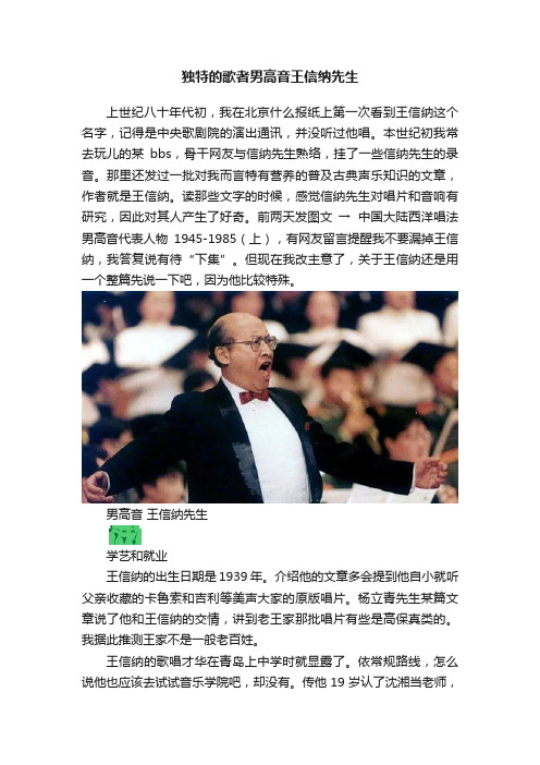
独特的歌者男高音王信纳先生上世纪八十年代初,我在北京什么报纸上第一次看到王信纳这个名字,记得是中央歌剧院的演出通讯,并没听过他唱。
本世纪初我常去玩儿的某bbs,骨干网友与信纳先生熟络,挂了一些信纳先生的录音。
那里还发过一批对我而言特有营养的普及古典声乐知识的文章,作者就是王信纳。
读那些文字的时候,感觉信纳先生对唱片和音响有研究,因此对其人产生了好奇。
前两天发图文→中国大陆西洋唱法男高音代表人物1945-1985(上),有网友留言提醒我不要漏掉王信纳,我答复说有待“下集”。
但现在我改主意了,关于王信纳还是用一个整篇先说一下吧,因为他比较特殊。
男高音王信纳先生学艺和就业王信纳的出生日期是1939年。
介绍他的文章多会提到他自小就听父亲收藏的卡鲁索和吉利等美声大家的原版唱片。
杨立青先生某篇文章说了他和王信纳的交情,讲到老王家那批唱片有些是高保真类的。
我据此推测王家不是一般老百姓。
王信纳的歌唱才华在青岛上中学时就显露了。
依常规路线,怎么说他也应该去试试音乐学院吧,却没有。
传他19岁认了沈湘当老师,次年却去了长春工作,这离沈湘先生所在的北京是又远了好多啊。
信纳先生19岁-39岁之间这二十年,怎样在沈大师的指导下学习的?未知。
王信纳在长春的工作单位是长影乐团,他在长春的声乐老师“玛利亚·山道夫斯卡娅”是位来自俄罗斯的女士。
俄罗斯歌者在东三省从事声乐教学的不少,这个事实有很多文献提到过。
长影乐团男高音李世荣先生也有跟俄国歌者学艺的履历,所以信纳先生这位业师是否大牌、是否著名我并不在意。
1963年公映的的悬疑片《冰山上的来客》集中了雷振邦创作的多首插曲,那里面有王信纳的声音。
塔吉克族新郎那乌鲁兹在自家屋顶上唱“戈壁滩上风沙弥漫……”,王信纳配的这歌。
有一些网文抄长影家属的说法,嗡嗡“冰山雪莲”那个男声是王信纳,一般人信了也就算了,以研究歌曲和声乐艺术的某些订阅号也被带节奏,真让我心烦。
稍微琢磨一下也可以判断吧,王信纳嗓子是那个味儿么?而且中唱发行的唱片也标注了那段歌的歌者啊(唱片版本和电影原声是一致的)。
- 1、下载文档前请自行甄别文档内容的完整性,平台不提供额外的编辑、内容补充、找答案等附加服务。
- 2、"仅部分预览"的文档,不可在线预览部分如存在完整性等问题,可反馈申请退款(可完整预览的文档不适用该条件!)。
- 3、如文档侵犯您的权益,请联系客服反馈,我们会尽快为您处理(人工客服工作时间:9:00-18:30)。
乙氧基喹啉(C14H19NO)
结构式:
化学名称:6-乙氧基-2,2,4-三甲基-1,2-二氢喹啉.
英文名称:6-ethoxy-2,2-4-trimethy-1,2-dihydro quinoline
物理性质:棕褐色液体,溶于醇,醚,甲苯,丙酮等有机溶剂,密度1.029-1.031(25℃)
用途:是一种优秀的新型抗氧化剂、杀虫剂和杀菌剂,主要用于饲料。
一.合成工艺探索
1.催化剂优化。
现有工艺使用催化剂为对甲苯磺酸与盐酸(质量比约1:1)混合物作催化剂,本次实验采用了苯磺酸和碘分别作催化剂做了两组平行实验。
探索催化剂和转化率的关系。
2.投料比优化
现有工艺投料比为(对乙:丙酮 = 1:2),本次实验探索了不同投料比对产率和转化率的影响。
3.反应温度优化
现有工艺反应温度控制在126-135℃,本实验对反应温度做了2组破坏性实验。
探索反应温度与转化率和产率之间的关系。
二.原油盐酸盐问题
因现有工艺洗涤过程中由于加盐酸导致原油中有盐酸盐结晶析出,导致管道堵塞,不利于下一步连续精馏。
故针对洗涤过程中盐酸的加量进行了一系列实验,探索盐酸的最佳加量。
通过数十组实验成功探索出原油洗涤过程中盐酸盐析出与盐酸加量的关系。
三.原油精馏
因现有工艺采用的七步洗涤过程过于繁琐,并且成本较为昂贵,故提出实验采用三步洗涤后精馏代替七步洗涤过程,本实验通过对三步法洗涤液的间歇精馏。
摸索出各组分在特定真空度(15mmHg)时,温度与含量的关系。