GM6011 限流开关
巨人通力调试资料

运通系列电梯调试作业指导目录一.调试流程图 --------—2 二.调试操作说明 ---——---—3 1.控制系统框图 -—-—-—---42.控制系统用户界面的操作流程——---—-——5-163.驱动部分——-—--———16-234.运行准备-—————----——---235.慢车运行 -——--——- 23-256.快车调试——-—---—25-287.门机调整 --—-————28—338。
平衡系数测定—--—————33-349.超载设定———--—--34—3510.功能检测——-----—35附录1 :LCECPU参数表——————-—35-67附录2:LCECPU故障代码 ---——-——67—77附录3:SIEI变频器参数设定说明 --—-——--77—81附录4:SIEI变频器故障代码 -—-—-—-—81-83附录5:门机参数及故障代码 ---——-—83—88附录6 :调试报告 -—---——89-961.控制系统框图:下图表是运通产品的电气系统的结构.它由许多pc板组成,2.控制系统用户界面的操作流程2.1 CPU用户界面的按钮2。
1。
1用户界面的按钮按钮和显示屏1.功能模式键2.功能模式的显示窗口3.楼层(轿厢位置)窗口4.新楼层(目标楼层)窗口5.增加数值/楼层键6.选择数值/接受键7.上召键8.内召键9.限速器测试(不使用)10.子菜单窗口11.数值(调整值)窗口12.减小数值/楼层键13.下召键14.缓冲测试功能模式功能模式显示用户界面未被激活无显示错误标志E(故障菜单)驱动设备错误 d电梯参数 1楼层标志 3显示和测试 4调试 5DRV参数 6电梯参数7外部群组参数82。
2.1LCE™用户界面的LEDs和按钮LEDsLCECPU板有绿色、红色和黄色的LEDs.他们的意义如下:绿色指正常操作电梯。
绿色的LEDs要一直打开红色指系统故障。
该状态需要工程师来处理黄色指操作模式.LEDs根据状态可以发光和不放光注意:中间列从"SPEED 〉0,1 M/S”到 "SAFETY INPUT"的LEDs也表示启动时序。
SCALANCE X101-1 商品说明书
24 V
6GK5101-1BB00-2AA3 Page 1/4
06/28/2018
Subject to change without notice © Copyright Siemens
● at DC / maximum
Supply voltage, current consumption, power loss Supply voltage ● external ● external Type of voltage / of the supply voltage Product component / fusing at power supply input Fuse protection type / at input for supply voltage Consumed current ● maximum Power loss [W] ● at DC / at 24 V
Compact 40 mm 125 mm 124 mm 0.55 kg
Yes Yes Yes
No No
FM3611: Class 1, Divison 2, Group A, B, C, D / T.., Class 1, Zone 2, Group IIC, T.. EN 600079-15 II 3 G EEx nA II T.. KEMA 06 ATEX 0021 X
Yes
Yes Yes Yes Yes Yes No 134 y
/snst
/simatic-net https:// /industry/infocenter /bilddb /cax https://
Security information
UL 60950-1, CSA C22.2 No. 60950-1 UL 1604 and UL 2279-15 (Hazardous Location), Class 1 / Division 2 / Group A, B, C, D / T.., Class 1 / Zone 2 / Group IIC / T.. EN 61000-6-3 EN 61000-6-4:2001 EN 61000-6-2:2001, EN 61000-6-4:2001 Yes Yes Yes
DS-19A08-BNG DS-19A08-BN网络报警小主机用户手册 V1.1介绍
产品型号
产品名称
DS-19A08-BN
网络报警小主机
DS-19A08-BNG
网络报警小主机
本手册可能包含技术上不准确的地方、或与产品功能及操作不相符的地方、或印刷错误。我公司将根 据产品功能的增强而更新本手册的内容,并将定期改进或更新本手册中描述的产品或程序。更新的内容将 会在本手册的新版本中加入,恕不另行通知。
杭州海康威视数字技术股份有限公司| 版权所有(C) --5--
DS-19A08-BNG网络报警小主机接线图
网络报警小主机.用户手册
电源指示灯
网络数据指示灯 网络状态指示灯
TIP RING TIP1 RING1
电话线
电源指示灯
电话机
电话机
电话线
注意 请勿对主机带电操作!
GPRS 天线座 工作状态指示灯 网络状态指示灯 电源指示灯
如下所示,预防措施分为“警告”和“注意”两部分: 警告:无视警告事项,可能会导致死亡或严重伤害。 注意:无视注意事项,可能会导致伤害或财产损失。
警告 事项提醒用户防范潜在的死亡或严重 伤害危险。
注意 事项提醒用户防范潜在的伤害或财产 损失危险。
警告 在本产品安装使用中,必须严格遵守国家和使用地区的各项电气安全规程。 在接线、拆装等操作时请一定要将电源断开,切勿带电操作。 如果设备工作不正常,请联系购买设备的商店或最近的服务中心,不要以任何方式拆卸或修改设备。
Z1 Z2
Z3 Z4
Z5 Z6
所有的EOL都是8.2K欧姆
Z7 Z8
警灯
警灯
警灯
报警输出接口
警灯
注意:
1、检修前要先断开所有交流电、电池和电话接头。 2、请确保主机接地端子可靠接地!主机内部具有多重防 雷保护设计,但这需要可靠接地为前提,否则这些防护措施 不能起到有效保护作用。接地电阻不大于8欧姆。
610 611 612可调设定点气体压差开关 报警器使用说明书 (2)
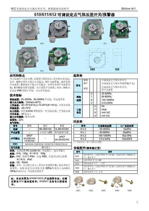
610/611/612可调设定点气体压差开关/报警器应用和特点用于监测空气等非可燃、非腐蚀气体的过压、真空和压差状态。
其中,610仅带有干接点开关输出;611为报警器,提供本地声光报警;612既有干接点开关输出,还带有本地声光报警功能。
611/612有静音按键,用于消除声音报警。
此外,610具有高达IP65的防护等级,可以室外使用。
技术指标量程范围:20~300Pa ,50~500Pa 等可选,详见选型表最大压力限制:10kPa(0~50°C)工作温度:-30~70°C(610)或-10~50°C(611/612),介质及环境存储温度:-40~70°C压力连接:内径6.0mm 塑料软管,“+”为高压端,“-”为低压端开关寿命:106次以上最大开关频率:6次/分钟重复性:±2%电气特性:型号610611612电源-85~250VAC 9~28VAC/DC 声光报警-红/绿色LED ,蜂鸣器/静音键开关输出SPDT2A/250VAC 1A/30VDC-SPST3A,30VDC/ACEMCGB14536.1/GB14536.7,IEC60730-1/IEC60730-2-6电气连接螺丝端子材质:壳体阻燃PC (UL94V-0),硅胶膜片,银合金触点重量:610:130g ,611/612:155g防护:610:标准型IP54,可选IP65,在选型后加后缀-S611/612:IP40认证:CE ,RoHS安装:垂直,压力接口向下。
此为开关校准位置。
如必须水平安装时,实际设定点比刻度点加20Pa(封盖向上)或减约10Pa(封盖向下),详见使用说明书选型表型号610可调设定点气体压差开关611可调设定点气体压差报警器(声光)612可调设定点气体压差开关,带声光报警量程范围020-300Pa 150-500Pa 2100-1000Pa 30.5-2.5kPa 工程单位0Pa 7mbar 8inch WC 9mm WC回差表型号可调量程范围工厂设定回差61x.020-300Pa 10±5Pa 61x.150-500Pa 20±8Pa 61x.2100-1000Pa 50±15Pa 61x.30.5-2.5kPa100±30Pa工厂设定回差,客户不能自行调整。
深圳市首韩科技有限公司限位开关说明书
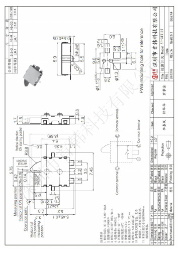
深圳市首韩科技有限公司限位开关深圳市首韩科技有限公司SHENZHEN SHOUHAN TECHNOLOGYCO.,LTDTel:*************Fax:*************客户Customer:产品名称Project:规格型号Part No:贵公司承认印Approal slgnatures料号/Part No.签章/Signatures日期Date:拟制/Drawn 李春风审核/Check 钟华华批准/Approved罗孝金1深圳市首韩科技有限SH-31R 11T1. 一般特性General Characteristics正常温度: 5℃~35℃ 相对湿度: 45%~85% 1.1 额定值(Rating Value): DC 5V 10mA1.2 工作温度(Work Temperature Range): -10℃ ~ 60℃1.3 存贮温度(Store Temperature Range): -20℃ ~ 80℃1.4 正常测试条件(未有特殊说明量测在以下条件进行):General test condition (Tests and measurements shall be made under the following standard conditions unless otherwise specified):RH 气 压: 8,600~10,600帕Temperature: 5℃~35℃ Relative humidity: 45%~85% Air pressure: 8,600~10,600 pa2. 产品外观及尺寸要求 Appearance & Dimension Requirement2.1 产品外形结构紧凑,无配合不良.The structure of product is compact, and assembly of parts has no badness.2.2 产品塑胶部件无严重缩水、披锋、欠注、斑点、破损或变形现象.The plastic parts of product have no serious defects such as very serious shrink, scarcity,fleck, disrepair, transmutation, etc.2.3 产品引脚和外壳无严重氧化、脏污、变形、毛刺或电镀不良.Lead feet and shell have no serious defects such as oxidation, smudge, disrepair, burr, defects on plating.2.4 开关操作顺畅,节奏感强,无明显卡塞现象。
莫贾EtherDevice EDS-G4008系列工业DIN-架Ethernet开关用户手册说明书

P/N: 1802040080111 *1802040080111*EDS-G4008 Series Quick Installation GuideMoxa EtherDevice™ SwitchVersion 1.1, November 2022Technical Support Contact Information/support2022 Moxa Inc. All rights reserved.Package ChecklistThe EDS-G4008 Series industrial DIN-rail EtherDevice Switch (EDS) is shipped with the following items. If any of these items are missing or damaged, please contact your customer service representative for assistance.• 1 EDS-G4008 Ethernet switch•Quick installation guide (printed)•Warranty card•Substance disclosure table•Product certificate of quality inspection (Simplified Chinese) •Product notices (Simplified Chinese)NOTE You can find information and software downloads on the relevant product pages located on Moxa’s website:Default Settings•IP address: 192.168.127.253•Subnet Mask: 255.255.255.0•Username: admin•Password: moxaPanel Views of EDS-G4008 SeriesFront Panel View Array1.1000BaseT(X) LED indicator2.10/100BaseT(X) LED indicator3.10/100/1000BaseT(X) ports,ports 1 to 84.Grounding connector screw5.Terminal blocks for power input,digital input, and relay output6.LED indicators: STATE (S),FAULT (F), PWR1 (P1), PWR2(P2), MSTR/HEAD (M/H),CPLR/TAIL (C/T), SYNC7.Console port (RJ45, RS-232)B storage port (type A,currently disabled)9.Model nameBottom Panel View1.microSD card slot Array (currently disabled)2.Reset button3.DIP switches for TurboRing, Ring Master, andRing CouplerMounting DimensionsDIN-rail MountingThe DIN-rail mounting kit is fixed to the back panel of the EDS device when you take it out of the box. Mount the EDS device on corrosion-free mounting rails that meet the EN 60715 standard.InstallationSTEP 1—Insert the upper lip ofthe DIN rail into the DIN-railmounting kit.STEP 2—Press the EDS devicetowards the DIN rail until itsnaps into place.RemovalSTEP 1—Pull down the latch onthe mounting kit with ascrewdriver.STEP 2 & 3—Slightly pull theEDS device forward and lift upto remove it from the DIN rail.NOTE Our DIN rail kit now utilizes a quick release mechanism to make it easier for users to remove the DIN rail from the EDS device.Wall Mounting (Optional)For some applications, you will find it convenient to mount the Moxa EDS device on a wall, as shown in the following illustrations: STEP 1—Remove the DIN-rail attachment plate from the rear panel of the EDS device, and then attach the wall mount plates with M3 screws.STEP 2—Mounting the EDS device on a wallrequires four screws. Use the EDS device, with wall mount plates attached. The heads of the screws should be less than 6.0 mm in diameter, and the shafts should be less than 3.5 mm in diameter, as shown in the figure on at right.NOTE Before tightening the screws into the wall, make sure the screw head and shank size are suitable by inserting the screw through one of the keyhole-shaped apertures of the Wall Mounting Plates.NOTE Do not screw the screws in all the way—leave about 2 mm toallow room for sliding the wall mount panel between the wall and the screws.STEP 3—Once the screws are fixed to the wall, insert the four screw heads through the wide parts of the keyhole-shaped apertures, and then slide the EDS devicedownwards, as indicated in the figure at the right.Tighten the four screws for more stability.Wiring RequirementsBe sure to read and follow these important points below:•Use separate paths to route wiring for power and devices. If power wiring and device wiring paths must cross, make sure the wires are perpendicular at the intersection point.NOTE Do not run signal or communications wiring and power wiring through the same wire conduit. To avoid interference, wireswith different signal characteristics should be routed separately. •You can use the type of signal transmitted through a wire to determine which wires should be kept separate. The rule of thumb is that wiring that shares similar electrical characteristics can bebundled together.•You should separate input wiring from output wiring.•We advise that you label the wiring to all devices in your system. Grounding the Moxa EDS SeriesGrounding and wire routing help limit the effects of noise due to electromagnetic interference (EMI). Run the ground connection from the ground screw (M4) to the grounding surface prior to connecting devices.NOTE The grounding wire should have a minimum diameter of1.5 mm2.Suggested Wire Type for Wiring Relay Contact (RELAY), Digital Input (DI), and Power Inputs (P1/P2)The EDS device includes two 4-pins 3.5 mm pin-pitch terminal blocks. When wiring the relay contact (RELAY), digital input (DI), and power inputs (P1/P2), we suggest using the cable type AWG 18-24 and the corresponding pin type cable terminals.NOTE The wire must be able to withstand at least 105°C and thetorque value should be 4.5 lb-in (0.51 N-m).NOTE We suggest the length of the pin type cable terminal is 8 mm. In order to tighten the wire properly, ① use a small flathead screwdriver to press the push-in button beside each terminal ofthe terminal block connector before and during ②inserting the wire. ③ Release the screwdriver after the wire has been fully inserted. Please refer to the diagram below.Wiring the Relay ContactThe EDS device has one set of relay output. This relay contact uses two contacts of the terminal block on the EDS’s power module. Refer to the section for detailed instructions on how to connect the wires to the terminal block connector, and how to attach the terminal block connector to the terminal block receptor.Relay:The two contacts of the 4-pin terminal block connector are used to detect user-configured events. The two wires attached to the fault contacts form an open circuit when a user-configured event is triggered or there is no power supply to the switch. If a user-configured event does not occur, the fault circuit remains closed.Wiring the Redundant Power InputsThe EDS device includes both high-voltage and low-voltage products. For the low-voltage (LV models) products, there are two power inputs for redundancy; for the high-voltage (HV models) products, there is only one power input. Refer to the instructions and diagram below on how to connect the wires to the terminal block connector on the receptor.STEP 1: Insert the Positive/Negative DC or Line/Neutral AC wires into the V+/V- or L/N terminals, respectively. STEP 2: To keep the DC or AC wires from pulling loose, use a small flat-blade screwdriver to tighten the wire-clamp screws on the front of the terminal block connector.STEP 3: Insert the plastic terminal block connector prongs into the terminal block receptor, which islocated on the EDS devices’ right side.Wiring the Digital InputsThe EDS device has one set of digital input (DI). The DI consists of two contacts of the 4-pin terminal block connector on the EDS's right-side panel. Refer to the instructions and diagram below on how to connect the wires to the terminal block connector on the receptor.STEP 1: Insert the negative(ground)/positive DI wires into the ┴/I terminals, respectively. STEP 2: To keep the DI wires from pulling loose, use a small flat-blade screwdriver to tighten the wire-clamp button on the front of the terminal block connector.STEP 3: Insert the plastic terminal block connector prongs into the terminal block receptor, which islocated on the EDS devices’ right side.Rotating the Power ModuleThe power module for the EDS device can be rotated to make it easier to fit your field site application.Step 1: Remove the two screws that fasten the power module to theEDS device and remove the module. Step 2: Turn the power module clockwise so that the power, digitalinput, and relay output connectors can be moved upwards. Step 3: Replace the module back on to the EDS device. Step 4: Fasten two screws on to the module.Communication ConnectionsEach EDS-G4008 Series switch has various types of communication ports: • RJ45 console port (RS-232 interface)• USB storage port (type A connector, currently disabled) • 10/100/1000BaseT(X) Ethernet ports •microSD card slot (currently disabled)Console Port ConnectionThe EDS device has one RJ45 console port (RS-232), located on the front panel. Use either an RJ45-to-DB9 (see the cable following wiring diagrams) to connect the EDS’s console port to your PC’s COM port. You may then use a console terminal program, such as Moxa PComm Terminal Emulator, to access the EDS that has a baud rate of 115200. RJ45 Console Port PinoutsPin Description1 DSR2 RTS3 –4 TxD5 RxD6 GND7 CTS 8DTRUSB ConnectionNOTE The USB function is currently reserved and may be required in the future. It should be noted that this port cannot be used for charging any devices.1000BaseT(X) Ethernet Port Connection1000BaseT(X) data is transmitted on differential TRD+/- signal pairs over copper wires.MDI/MDI-X Port PinoutsPinSignal 1 TRD(0)+ 2 TRD(0)- 3 TRD(1)+ 4 TRD(2)+ 5 TRD(2)- 6 TRD(1)- 7 TRD(3)+ 8TRD(3)-Reset ButtonThere are two functions available on the Reset Button. One is to reset the Ethernet switch to factory default settings by pressing and holding the Reset button for 5 seconds. Use a pointed object, such as a straightened paper clip or toothpick, to depress the Reset button. This will cause the STATE LED to blink once a second. After depressing the button for 5 continuous seconds, the STATE LED will start to blink rapidly. This indicates that factory default settings have been loaded and you can release the reset button. The other function is to reboot the device by depressing the reset button for less than five seconds. Turbo Ring DIP Switch SettingsThe EDS devices are plug-and-play managed redundant Ethernet switches. The proprietary Turbo Ring protocol was developed by Moxa to provide better network reliability and faster recovery time. Moxa Turbo Ring’s recovery time is less than 50 ms (Turbo Ring V2) —compared to a 3- to 5-minute recovery time for commercial switches—decreasing the possible loss caused by network failures in an industrial setting.There are five Hardware DIP Switches for Turbo Ring on the bottom panel of the EDS device that can help setup the Turbo Ring easily within seconds. If you do not want to use a hardware DIP switch to setup the Turbo Ring, you can use a web browser, telnet, or console to disable this function.NOTE Please refer to the Turbo Ring section in User's Manual for more detail information about the setting and usage of TurboRing V2.Turbo Ring DIP Switch Settingsfollowing table explains the effect of setting the DIPSwitch to the ON position.Remove the rubber cover on the bottom panel ofthe device to expose the DIP switches.DIP Switch SettingsNOTE You must enable the Turbo Ring (DIP switch 5) first before using the DIP switch to activate the Master and Couplerfunctions.NOTE If you do not enable any of the EDS switches to be the Ring Master, the Turbo Ring protocol will automatically choose theEDS switch with the smallest MAC address range to be the RingMaster. If you accidentally enable more than one switch to bethe Ring Master, these switches will auto-negotiate todetermine which one will be the Ring Master.LED IndicatorsThe front panel of the Moxa EDS-G4008 Series contains several LED indicators. The function of each LED is described in the following table: Device LED IndicatorsLED Color State DescriptionSTATE GreenOnWhen system has passedpower-on self-test (POST) and isready to run.Blinking(1 time/sec)Press the reset button for fiveseconds to reset to factorydefault settingsBlinking(4 times/sec)When pressing the reset buttondepress for 5 seconds to resetto factory default.Off N/ARed OnThe system has initially failedthe boot-up process•System Info. Read Fail orEEPROM information errorFAULT Red On1.The relay contact has beentriggered2.The ingress rate limit hasbeen exceeded and the porthas entered shut downmode3.Invalid Ring port connection OffWhen the system boots up andruns correctly or a user-configured event is nottriggered.P1 Amber On Power is being supplied to power input PWR.Off Power is not being supplied topower input PWR.P2 Amber On Power is being supplied to power input PWR.Off Power is not being supplied topower input PWR.LED Color State Description MSTR/HEAD (M/H) GreenOnWhen the switch isMaster/Head/Root of TurboRing/Turbo Chain/Fast RSTP.Blinking(4 times/sec)1.The switch has become theMaster of Turbo Ring afterTurbo Ring has gone down2.The switch is set as Head ofTurbo Chain and TurboChain has gone down3.The switch is set as theTurbo Ring’s Member andthe corresponding Ring portis down4.The switch is set as theTurbo Chain’s Member/ Tailand the correspondingHead-end Chain port isdown.OffWhen the switch is not theMaster/Head/Root of this TurboRing/ Turbo Chain/Fast RSTP.CPLR/ TAIL GreenOn1.The switch’s ring coupling ordual homing function isenabled.2.The switch is set as the Tailof Turbo Chain.Blinking(4 times/sec)1.The switch is set as the Tailof Turbo Chain and theChain has gone down.2.The switch is set as theTurbo Chain’s Member/Head and the correspondingTail-end Chain port is down.OffWhen the switch disables thecoupling or tail role of TurboChain.System LED (Except PWR) Green +Amber +RedBlinking(2 times/sec)The switch is beingdiscovered/located by thelocator function.System LED (Except PWR) Green +Amber +RedRotateOn -> OffSequentiallyThe switch isimporting/exporting a file viaABC-02-USB or SD card(currently disabled).Ports LED IndicatorsLED Color State Description 10M/100M/1000M Copper top LED GreenOn When the port is active and linksat 1000Mbps.Blinking(4 times/sec)When the port’s data is beingtransmitted at 1000Mbps.Off When the port is inactive or linkdown.10M/ 100M/1000M Copper bottom LED AmberOn When the port is active and linksat 10/100Mbps.Blinking(4 times/sec)When the port’s data is beingtransmitted at 10/100Mbps.Off When the port is inactive or linkdown.SpecificationsInterfaceRJ45 Ports 10/100/1000BaseT(X)Console Port RS-232 (RJ45)Button Reset buttonLED Indicators STATE (S), FAULT (F), PWR1 (P1), PWR2 (P2),MSTR/HEAD (M/H), CPLR/TAIL (C/T), SYNC Alarm Contact 1 normally open electromagnetic relay output withcurrent carrying capacity of 1 A @ 24 VDC Digital Input 1 isolated digital input:+13 to +30V for state “1”-30 to +3V for state “0”Max. input current: 8 mAPowerPre-installed Power Module -LV/-LV-T models: PWR-100–LV -HV/-HV-T models: PWR-105-HV-INote The EDS-G4008 Series supports modular powersupplies. The model names and power parametersare determined by the installed power module.For example:EDS-G4008-T + PWR-100-LV = EDS-G4008-LV-TEDS-G4008-T + PWR-105-HV-I = EDS-G4008-HV-TIf you install a different power module, refer to thespecifications of the corresponding model. Forexample, if you replace the power module of theEDS-G4008-LV-T with the PWR-105-HV-I, refer tothe specifications of the EDS-G4008-HV-T.Rated Voltage -LV/-LV-T models: 12/24/48 VDC, redundant dualinputs-HV/-HV-T models: 110/220 VDC/VAC, single input Operating Voltage -LV/-LV-T models: 9.6 to 60 VDC-HV/-HV-T models: 88 to 300 VDC, 85 to 264 VAC Rated Current -LV/-LV-T models: 12-48 VDC, 1.50-0.40 A or 24VDC, 0.70 A-HV/-HV-T models: 110-220 VAC, 50-60 Hz, 0.30-0.20 A or 110-220 VDC, 0.30-0.20 APower Consumption EDS-G4008-LV(-T) models: 8.84 W EDS-G4008-HV(-T) models: 10.73 WInrush Current Max. 0.58 A @ 48 VDC (0.1 – 1 ms) (Applied to -LV models)Overload CurrentProtection at InputPresentReverse PolarityProtectionPresentConnection 2 removable 4-contact terminal blocks Physical CharacteristicsHousing Metal, IP40 protectionDimension 55 x 140 x 120 mm (2.17 x 5.51 x 4.72 in) Weight 859.5 g (1.89 lb)Installation DIN-rail mounting, wall mounting (with optionalkit)Environmental LimitsOperating Temperature -10 to 60°C (14 to 140°F) for standard models -40 to 75°C (-40 to 167°F) for -T modelsStorageTemperature-40 to 85°C (-40 to 185°F)Ambient RelativeHumidity5 to 95% (non-condensing)Altitude Up to 2000 mNote: Please contact Moxa if you require productsguaranteed to function properly at higher altitude. Regulatory ApprovalsIndustrialCybersecurityIEC 62443-4-1, IEC 62443-4-2Safety UL 61010-2-201, EN 62368-1(LVD)EMC EN 55032/35, EN 61000-6-2/6-4EMI FCC Part 15 Subpart B Class AEMS EN 61000-4-2 (ESD) Level 4EN 61000-4-3 (RS) Level 3EN 61000-4-4 (EFT) Level 4EN 61000-4-5 (Surge) Level 4EN 61000-4-6 (CS) Level 3EN 61000-4-8 Level 4Shock IEC 60068-2-27Free Fall IEC 60068-2-32Vibration IEC 60068-2-6Hazardous Location Class I Division 2, ATEX, IECExRail Traffic(Wayside)EN 50121-4Traffic Control NEMA TS2WarrantyWarranty 5 yearsHazardous Location Information (except for PoE and HV models)ATEXinformationII 3G Ex ec nC IIC T4 GcUL 22 ATEX 2741XAmbient Range: -40°C ≤ Tamb ≤ +75°C for -T models Ambient Range: -10°C ≤ Tamb ≤ +60°C for models without “-T”Rated Cable Temp. ≥ 90.4°CWARNING-DO NOT SEPARATE WHEN ENERGIZEDIECExCertificate no. IECEx UL 22.0031XAddress of manufacturer No. 1111, Heping Rd., Bade Dist., Taoyuan City 334004, TaiwanStandards and CertificationsHazardous LocationIEC 60079-0, Edition 7 IEC 60079-7, Edition 5.1 IEC 60079-15, Edition 5 EN IEC 60079-0:2018EN IEC 60079-7:2015+A1:2018 EN IEC 60079-15:2019Specific Condition of Use•The equipment shall only be used in an area of at least pollution degree 2, as defined in IEC/EN 60664-1.•The equipment shall be installed in an enclosure that provides a minimum ingress protection of IP 54 in accordance with IEC/EN 60079-0 and accessible only by use of a tool.。
Metro3000 SS61EMS1V1R1配置书

1.1 业务和保护功能的配置1.1.1 安装以太网接口板在主菜单中选择[配置/以太网配置/以太网接口板管理]。
从左下角选择操作对象(以太网单板),单击按钮,然后在界面右边进行相应属性的设置。
如果需要查询以太网接口板信息,单击<查询>,则从网元侧返回所选以太网单板的接口板信息。
如果需要新建以太网接口板信息,单击<新建>,或者在右边的接口板列表中单击鼠标右键,选择[新建],在接口板列表中将出现这条新增加的接口板。
选中这条接口板,单击相应属性部分,在下拉菜单中选择适当的值。
如果需要删除以太网接口板信息,选中需要删除的以太网接口板,单击<删除>,或者在右边的接口板列表中单击鼠标右键,选择[删除]。
单击<应用>。
说明:有一些设备,以太网接口单元是集以太网处理板和以太网接口板于一身,不需要单独配置以太网接口板,如OptiX 155/622H(Metro1000)设备,此时可以省去此步骤。
还有一些设备,以太网接口单元实现以太网处理板和以太网接口板的分离,所以需要配置以太网接口板,如OptiX 2500+(Metro3000)、OptiX Metro3100设备。
此时就要完成此步骤。
1.1.2 配置以太网接口的端口属性和绑定通道在主菜单中选择[配置/以太网配置/以太网接口管理]。
从左下角选择操作对象(以太网单板),单击按钮,然后在界面右边进行相应属性的设置。
选择“内部端口”,对内部端口进行设置。
选择“端口属性”选项页,单击<查询>,则从网元侧返回所选以太网单板的内部端口的端口信息。
设置每个内部端口TAG标识、“VALN ID等参数。
单击<应用>。
选择“绑定通道”选项页,单击<查询>,则从网元侧返回所选以太网单板的内部端口的绑定通道信息。
单击<配置>,进入“绑定通道配置”窗口。
选择可配置端口,绑定通道的级别、方向,VC4及时隙。
西门子 S7-1200 功能安全手册 - 设备手册说明书
SIMATICS7S7-1200 功能安全手册设备手册Siemens AGDigital IndustriesⓅ 10/2022 本公司保留更改的权利 Copyright © Siemens AG 2022. 保留所有权利法律资讯警告提示系统为了您的人身安全以及避免财产损失,必须注意本手册中的提示。
人身安全的提示用一个警告三角表示,仅与财产损失有关的提示不带警告三角。
警告提示根据危险等级由高到低如下表示。
危险表示如果不采取相应的小心措施,将会导致死亡或者严重的人身伤害。
警告表示如果不采取相应的小心措施,可能导致死亡或者严重的人身伤害。
小心表示如果不采取相应的小心措施,可能导致轻微的人身伤害。
注意表示如果不采取相应的小心措施,可能导致财产损失。
当出现多个危险等级的情况下,每次总是使用最高等级的警告提示。
如果在某个警告提示中带有警告可能导致人身伤害的警告三角,则可能在该警告提示中另外还附带有可能导致财产损失的警告。
合格的专业人员本文件所属的产品/系统只允许由符合各项工作要求的合格人员进行操作。
其操作必须遵照各自附带的文件说明,特别是其中的安全及警告提示。
由于具备相关培训及经验,合格人员可以察觉本产品/系统的风险,并避免可能的危险。
按规定使用 Siemens 产品请注意下列说明:警告Siemens 产品只允许用于目录和相关技术文件中规定的使用情况。
如果要使用其他公司的产品和组件,必须得到 Siemens 推荐和允许。
正确的运输、储存、组装、装配、安装、调试、操作和维护是产品安全、正常运行的前提。
必须保证允许的环境条件。
必须注意相关文件中的提示。
商标所有带有标记符号 ® 的都是 Siemens AG 的注册商标。
本印刷品中的其他符号可能是一些其他商标。
若第三方出于自身目的使用这些商标,将侵害其所有者的权利。
责任免除我们已对印刷品中所述内容与硬件和软件的一致性作过检查。
然而不排除存在偏差的可能性,因此我们不保证印刷品中所述内容与硬件和软件完全一致。
NGC2
1 1
1 1
1 1
1 1
3(4) 3(4)
1000 800
3(4) 3(4)
1000 800
注:1、NA1是主选断路器,也可选用其它性能更先进进口 F、MT系列断路器。 2、01、02、04方案如PE+N线需进人电源柜 时柜宽用括号内尺寸。 3、SDL、SDH是GCS柜专用电流互感器。
09
10
11
12
单元、1单元、1.5单元、2
单元、3
单元五个尺寸系列。单元回
路额定电流400,其宽度、深度尺寸不变。相同功能单元的抽屉具有良好的互换性。
c. 每台MCC柜最多能安装11个一单元的抽屉或 22 个单元的抽屉。
d. 抽屉进出线根据电流大小采用不同片数的同一规格片式结构的接插件。
交流操作部分的辅助方案主要用于厂矿企业及高层建筑的变电所的低压系统。有 6 种适用于双电 源操作控制的组合方案。并设有操作电气联锁备用自投、自复等控制电路,工程设计中可以直接采用。
P1.
低压开关设备类
直流控制电源为直流 220V 或 110V,交流控制电源为交流380V或220V,由抽屉单元组成的成套
1600
2(60×6)
2000
2(60×10)
2500
2(80×10)
3150
2×2(60×6)
4000
2×2(60×10)
b. 垂直母线: 用于抽屉的垂直母线采用“L”形硬铜搪锡母线。 L形母线规格(mm):50×30×5 额定电流1000A。
c. 中性接地母线: 采用硬铜排。贯通水平中性接地线 (PEN) 或接地 + 中性线(PE+N)规格(见表3)。
2 型号及其含义
KISSLING G13限位开关说明书

KISSLINGLIMIT SWITCHSeries G13 - from TE Connectivity (TE)Switch meets specific shock and vibration levelsEnvironmentally sealed G13 limit switches can be integrated in many vehicles, which need to fulfill specific shock and vibration related requirements.The KISSLING G13 limit switches meet high requirements for function and reliability under extreme conditions and become a valuable elec-tric component in every vehicle application to ensure dependability.The G13 limit switch complies i.a. with VG 95210 for shock and vibration and meets MIL-S-8805. Many of our G13 limit switches are also NSN (NATO Stock Number) listedThe locking functionSwitches with locking mechanisms are manually operated switch-es with two switching positions. The change-over from switching position 1 to switching position 2 occurs whenever the actuation knob has been firmly pressed down.The switch remains locked in switching position 2. Twisting the actua-tion knob in the direction of the arrow will release the locking mecha-nism and the switch will snap back into switching position 1.Features• Military grade switch (VG 95210; MIL-S-8805)• 1- and 2-pole versions• Available with silver or gold contacts • Shock (100G) and vibration (15G) • Different actuator options available• Aluminum housing; special versions with resistance to salt and seawaterApplications• Commercial and military motor vehicles • Military ground equipment and vehicles • Plant and industrial engineering • Marine applications•Aviation ground support equipmentCircuits BC (C) AB (NC)C (NO)F (NO)E (NC)(C) D(C) A B (NC)C (NO)Single PoleDouble PoleSpecificationTechnical DataHousing Material | Special type AI-alloy | salt- and seawater resistance Temperature range | Special type -55°C to +85°C | -55°C to +125°C Protection (connected)IEC 60529, IP67 (0,2 bar, 5min)Vibration i.a.w. MIL-STD-202;Method 204; Test condition B (10-2000 Hz)15g Shock i.a.w. MIL-STD-202;Method 213; Test condition I (6 ms; sawtooth)100g Insulation resistance i.a.w MIL-STD-202;Method 302; Test condition B (500 V; 1 min)min. 100 M ΩDielectric withstanding voltage i.a.w MIL-STD-202; Method 3011050VACmax. approach speed at an angle of <30°Ball, Dome Roller5m/min 30m/min Operating force without looking 15 or 30 ± 5 N Operating force with lookingapprox. 60 ± 5 N Endurance without lookingi.a.w. MIL -S-8805; §4.8.26 (28 VDC; 1 Amps)i.a.w. MIL -S-8805; §4.8.26 (28 VDC; 5 Amps)only silver contacts100.000 cycles 25.000 cyclesEndurance with lookingi.a.w. MIL -S-8805; §4.8.26 (28 VDC; 5 Amps)only silver contacts mecanical10.000 cycles 10.000 cyclesSwitch inserts TypeMS 24547-1 / silverMS 24547-2 / goldi.a.w. MIL-S-8805up to +82°C up to +82°C Electrical rating max.min.max.min.Resistive load 28VDC, 7A 15VDC, 10mA 28VDC, 1A 15VDC, 5mA inductive load 28VDC, 7A5VDC, 20mA28VDC, 0.5A5VDC, 10mAMounting dimensions M20x1M16x1M12x1Mounting hole: with locking ringTechnical drawingsSWITCH WITH LOCKING MECHANISMExampleG13-01-1183 (SILVER)G13-01-1641 (GOLD)Example G13-01-1550 (GOLD)Example G13-01-1167 (SILVER)Example G13-01-1689 (SILVER)Example G13-01-1133 (SILVER)ExampleG13-01-1220 (2-POLE, SILVER, RED)G13-01-1629 (2-POLE, GOLD, RED)G13-01-1585 (2-POLE, SILVER, GREEN)G13-01-1470 (WITH CONNECTOR CECC 75201, RESISTANT TO SALTWATER)ExampleG13-01-1097 (1-POLE, SILVER)ExampleG13-01-1365 (2-POLE, SILVER)Housing dimension miniHousing dimension smallHousing dimension largeTE Connectivity, TE, TE connectivity (logo) and KISSLING (word) are trademarks owned or licensed by the TE Connectivity family of companies. All other logos, products and/or company names referred to herein might be trademarks of their respective owners.The information given herein, including drawings, illustrations and schematics which are intended for illustration purposes only, is believed to be reliable. However, TE Connectivity makes no warranties as to its accuracy or completeness and disclaims any liability in connection with its use. TE Connectivity‘s obligations shall only be as set forth in TE Connectivity‘s Standard Terms and Conditions of Sale for this product and in no case will TE Connectivity be liable for any incidental, indirect or consequential damages arising out of the sale, resale, use or misuse of the product. Users of TE Connectivity products should make their own evaluation to determine the suitability of each such product for the specific application.© 2020 TE Connectivity | All Rights Reserved. K1166743 | Version 08/2020Available typesHousing dimensions ActuatorLength of thread mm Mounting thread Width across flats Switch inserts Connector (Standard)cable (option)mini Dome Roller 14 - 18M12SW17single poleH8-3APN VG 95328/MIL-C-26482smallBall Dome Manual18 - 36M12SW17single poleH8-3APN VG 95328/MIL-C-26482largeBall Ball RollerManual with lock-ing mechanism red, green, black14 - 3618 - 3014 - 30 30M12M16M16M20SW17SW22SW22SW27single or double poleA10-SL-3PN VG 95234A10-98PN VG 96912C10-6PN VG 95328/MIL-C-26482MIL-C-D38999。
日立HTD31-4t0110e调试资料

日立HTD31-4t0110e调试资料
一、基准电压的调整
1、测量MPU板上MUJ1点调节0CA使电压为5.0±0.05V
2、测量BDC板上TESTUV1、4点调节HUVA使电压为8.0±0.05v
3、测量BDC板上TESTOB
4、5点调节OVBRA使电压为8.0±0.05V
二、慢车运转的调整
1、人为使轿门开关GS闭合。
2、门机电阻箱内15A断开,25A短接。
(SDC上MIC22及MIC34(FML)不要拔掉)
3、FIO板上13号插件的1、2号线短接。
4、操纵箱的[灯]、[点检灯]开关转换于[入]状态。
5、轿内操纵箱的[平常转换于保守],即可以在轿箱内操作慢车运转的状态。
6、电梯检修向上、向下点动运行。
三、阶高测定
1、先用检修开至上、下限位两开关动作时,确认轿箱超出平层50mm以外。
2、检修下行直到下限位动作的位置,保守开关处于正常,点检灯处于专用。
3、资料检索器上操作MODE 11 SET,持续押住START键,直到电梯开始上行运转为止。
4、到达最上层后,确认5OB断开。
此时将MPU的DIP SW1转换为ON,再等到50B灯亮之后,将DIPSW1转换OFF。
5、阶高测定完后,按MODERESET复位。
6、最后做一次故障清除。
四、启动舒适感的调整
1、60m/min 15人乘以下使用WD20%的启动补偿调整方法a:先将轿厢下设有20%和110%的微动开关调整精确。
b:载重20%以下,再拨DIPSW1ON。
用资料检索器输入MODE 33 SET调整启动时的飞出、反转状态。
600-1200VDC过流保护联接器GXSA16说明书

G XSA16600+ Amp 12-800 VdcOver Current ContactorFEATURESChassis level power terminals – No need for specially routed power cables, special bus bars, or special lugs.Rugged EPIC® seal rated to 175°C – Reduced risk of fire or meltdown in over current conditions.The same technology used for advanced aerospace programs.Hermetically sealed – Designed to meet: UL1604 for Class I & II, Div 2 and Class III for use in hazardous locations, IP67 for temporary water immersion for 30 min, IP69K for pressure washing, SAE J1171 - external ignition protection, and ISO8846 for protection against ignition around flammable gasses.High Efficiency Dual DC Coils – Very low 12 or 24 VDC continuous coil power with no EMI emissions or cross- talk on your system control power. Ideal for battery powered systems or where low power is needed.Built-in coil suppression for all DC coils – Saves you engineering time and parts cost to add external coil suppression.Stainless steel nuts and mounting inserts, for years of corrosion free service.Not position sensitive – can be mounted in any position for ease of installation.COIL RATINGS at 25˚CPRODUCT SPECIFICATIONSCURRENT CARRY vs TEMPERATUREwith 400MCM conductorPART NUMBER SYSTEMNotes & Definitions:1 Auxillary contact rating is 2A, 24Vdc Resistive load, 100,000 cycles. Minimum current is 0.1mA, 5V. The auxiliary contact is mechanically linked to the main power contacts.2 Contact resisitance measured at currents higher than 100A.3 Operation time is measured at 25°C and includes maximum 7ms bounce.4 Insulation resistance is 50 Mohms after life.5 Contactor can operate up to 125°C in special cases - contact GIGAVAC for details.6 Contactor has two coils. Both are used for pick-up, and then in approximately 75 milliseconds, one coil is electronically removed from the coil drive circuit. The remaining coil supplies low continuous hold power sufficient for the contactor to meet all of its specified performance specifications. This provides low coil power without PWM electronics that can cause EMI emissions and/or cross-talk on control power.7 Contactor is operated by a coil that changes resistance with temperature. Since pick-up current, coil current and coil power are specified at nominal voltage, they will be lower than indicated at temperatures above 25°C and higher than indicated at temperatures below 25°C. Similarly, pick-up and drop-out voltages will be higher than indicated at temperatures above 25°C and lower than indicated at temperatures below 25°C.8 For pick-up testing of contactors with dual coils, the voltage can not be ramped up slowly, but must be applied instantly to at least the maximum pick-up voltage. Otherwise, the contactor will not pick-up.9 Limit make current to 600A to avoid contact welding. For AC power switching cycles, contact factory.10 Coils are switched internally with a FET, so no fly-back/suppression voltage is seen at the coil inputs.APPLICATION NOTES•Power switching lifecycles are based on current flow from A2(+) to A1(-). For best breaking performance, the contactor should be installed so that current flows from A2(+) to A1(-). There are cases where the contactor will interrupt power in the opposite direction but please contact GIGAVAC to confirm suitability. Direction of current flow is not relevant during make or when flowing on closed contacts. For bi-directional contactors, please contact GIGAVAC.•Applications with capacitors will require a pre-charge circuit.•Electrical life rating is based on resistive load with 27µH maximum inductance in circuit. Because your application may be different, we suggest you test the contactor in your circuit to verify life is as required.•End of life is defined as when the dielectric, insulation resistance or contact resistance fails the specifications listed.OVER CURRENT OPERATION•With power applied to Vin, the contacts will close when Vcontrol is greater than Vcontrol:Close and open when Vcontrol is less than Vcontrol:Open (see Settings Parameters for values). Connect Vcontrol to Vin to disable logic level control.Datasheets provided by Sensata Technologies, Inc., its subsidiaries and/or affiliates (“Sensata”) are solelyintended to assist third parties (“Buyers”) who are developing systems that incorporate Sensata products (also referred to herein as “components”). Buyer understands and agrees that Buyer remains responsible for using its independent analysis, valuation, and judgment in designing Buyer’s systems and products. Sensata datasheets have been created using standard laboratory conditions and engineering practices. Sensata has not conducted any testing other than that specifically described in the published documentation for a particular datasheet. Sensata may make corrections, enhancements, improvements, and other changes to its datasheets or components without notice.Buyers are authorized to use Sensata datasheets with the Sensata component(s) identified in each particular datasheet. HOWEVER, NO OTHER LICENSE, EXPRESS OR IMPLIED, BY ESTOPPEL OR OTHERWISE TO ANY OTHER SENSATA INTELLECTUAL PROPERTY RIGHT, AND NO LICENSE TO ANY THIRD PARTY TECHNOLOGY OR INTELLECTUAL PROPERTY RIGHT, IS GRANTED HEREIN. SENSATA DATASHEETS ARE PROVIDED “AS IS”. SENSATA MAKES NO WARRANTIES OR REPRESENTATIONS WITH REGARD TO THE DATASHEETS OR USE OF THE DATASHEETS, EXPRESS, IMPLIED, OR STATUTORY, INCLUDING ACCURACY OR COMPLETENESS. SENSATA DISCLAIMS ANY WARRANTY OF TITLE AND ANY IMPLIED WARRANTIES OF MERCHANTABILITY, FITNESS FOR A PARTICULAR PURPOSE, QUIET ENJOYMENT, QUIET POSSESSION, AND NON-INFRINGEMENT OF ANY THIRD PARTY INTELLECTUAL PROPERTY RIGHTS WITH REGARD TO SENSATA DATASHEETS OR USE THEREOF.All products are sold subject to Sensata’s terms and conditions of sale supplied at . SENSATA ASSUMES NO LIABILITY FOR APPLICATIONS ASSISTANCE OR THE DESIGN OF BUYERS’ PRODUCTS. BUYER ACKNOWLEDGES AND AGREES THAT IT IS SOLELY RESPONSIBLE FOR COMPLIANCE WITH ALL LEGAL, REGULATORY, AND SAFETY-RELATED REQUIREMENTS CONCERNING ITS PRODUCTS, AND ANY USE OF SENSATA COMPONENTS IN ITS APPLICATIONS, NOTWITHSTANDING ANY APPLICATIONS-RELATED INFORMATION OR SUPPORT THAT MAY BE PROVIDED BY SENSATA.Mailing Address: Sensata Technologies, Inc., 529 Pleasant Street, Attleboro, MA 02703, USA Regional head offices:United States of AmericaSensata TechnologiesAttleboro, MAPhone: 508-236-3800E-mail:******************* NetherlandsSensata Technologies Holland B.V. HengeloPhone: +31 74 357 8000E-mail:*******************ChinaSensata Technologies China Co., Ltd. ShanghaiPhone: +8621 2306 1500E-mail: ******************* CONTACT USCopyright © 2023 Sensata Technologies, Inc.。
FC31 P.C. 优先流量调节器流量控制器系列 FP101 商品说明说明书

CV
Pressure vs. Priority Flow Minimum Operating Pressure
Check Valves
GPM LPM 8 30.0
Hydraulic Oil 150 SSU @ 100°F (32 cSt)
GPM LPM 10 37.5
Hydraulic Oil 150 SSU @ 100°F (32 cSt)
Accuracy (Fixed) ±20%
Adjustment Range ±20% Nominal (Adj. Version)
Cartridge Material All parts steel. All operating parts hardened steel.
Operating Temp. Range/Seals
Shuttle Valves
Load/Motor Controls
FC
Flow Controls源自Bodies & Cavities
Coils & Electronics
Proportional Valves
Solenoid Valves
Manual Valves
Directional Controls
4P 1/4″ NPTF (B10-3-*4P) 6P 3/8″ NPTF (B10-3-*6P) 8P 1/2″ NPTF (B10-3-*8P)
6T SAE-6 8T SAE-8
(B10-3-*6T) (B10-3-*8T)
6B 3/8″ BSPG (B10-3-6B)† 8B 1/2″ BSPG (B10-3-*8B)
56.3 LPM (15 GPM)
Minimum Inlet Flow
ELK-6011 v2 无线单按钮抢救传感器指南说明书
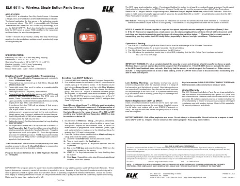
The 6011 has a single activation button. Pressing and holding this button for at least 2 seconds will cause a wireless Keyfob event 4 activation to be transmitted to the M1 Control. Wireless Keyfob event 4 must be programmed as a 24hr Police Panic alarm. Refer to the M1 Keypad Installer programming menu [Wireless Setup > Keyfob Defintions] or the ElkRP Software. While the button is held, and continuing for approximately 5 seconds, the single Red LED on the 6011 should blink to confirm that the 24hr Police Panic alarm has been activated.
Supervised. 4d. Skip to the TXID box and enter the Sensor TXID from the
printed label located on the sensor. 4e. LOOP # - For Keychain remotes the Loop # setting does
not matter! 4f. Click Save. Repeat the entire step 4 for each additional
- 1、下载文档前请自行甄别文档内容的完整性,平台不提供额外的编辑、内容补充、找答案等附加服务。
- 2、"仅部分预览"的文档,不可在线预览部分如存在完整性等问题,可反馈申请退款(可完整预览的文档不适用该条件!)。
- 3、如文档侵犯您的权益,请联系客服反馈,我们会尽快为您处理(人工客服工作时间:9:00-18:30)。
芯片应用电路
GM6011 限流开关Fra bibliotek产品概述GM6011 限流开关芯片实现对线路的电流进行检测,当线路上的电流大于设置的电流 值,芯片输出一个 TTL 报警信号,同时将线路断开,经过 1ms 时间的关断后,可以自动实 现重起动;芯片检测电源电压,当电源电压达到额定值的 110%或电压降低到额定值的 90 %时,都输出 TTL 报警信号,同样要将线路断开,并设计有电压迟滞重启动功能;内置过 热保护电路。 限流开关技术采用高压、低导阻器件来实现电源的通断控制。电源电流监测准确,并采 用高速比较器来实现限流开关的通断。芯片符合《GJB597A-96 半导体集成电路总规范》B 级要求。封装为 CDIP24。
特性
� � � � � 电源电压(VCC) : 5V~32V 工作环境温度(TA) : -55℃~125℃ 限制的电流量,可以检测的最大电流为 2.5A,并从 0.7A 到 2.5A 可调 采用高速比较器,截止时间小于 200ns 具有 1mS 自动重启功能
应用说明
下图是 GM6011 的应用电路图。
