倍加福NJ50-FP-W0-P1
电子电路保护设备说明书
RF1534-000SRP120F LR4-730F SRP200FTE Circuit Protection, a pioneer of polymeric positiveFeatures• RoHS compliant• Lead-free versions of all devices are available• Broad range of resettable devices available• Current ratings from 1.1A to 13A• Voltage ratings from 6V to 30V• Agency recognition: UL, CSA, TÜV• Fast time-to-trip• Low resistance• Digital camera battery packs• Portable media player battery packs• Power tools (charge line)11VLR VLP VTP MXP SRP LR4 Hold Typical Activation TemperatureCurrent (A) 85°C 90°C 90°C 120°C 125°C 125°C1.10 — — 16V/0.054V— — —1.20 — 16V/0.053V— — 15V/0.123V—1.70 12V/0.025V— 16V/0.041V— — —1.75 12V/0.024V16V/0.032V16V/0.040V— 15V/0.070V—1.80 — — — 6V/0.0105V— —1.90 — — — 6V/0.011V— 15V/0.056V2.00 — — — — 30V/0.045V—2.10 — 16V/0.024V16V/0.024V— — —2.20 — 16V/0.023V— — — —2.30 12V/0.015V— — — — —2.50 — — — 6V/0.011V— —2.60 — — — — — 15V/0.031V2.70 — 16V/0.015V— 6V/0.0105V— —3.10 — — — 6V/0.0075V— —3.50 — — — — 30V/0.024V—3.70 — — — 6V/0.007V— —3.80 — — — — — 15V/0.020V4.20 — — — — 30V/0.018V—4.50 — — — — — 20V/0.016V5.50 — — — — — 20V/0.013V6.00 — — — — — 20V/0.011V7.30 — — — — — 20V/0.009V9.00 — — — — — 20V/0.008V13.00 — — — — — 20V/0.006VApplication Selection Guide for Strap Battery DevicesMobile Phone Battery Packs Li-ion Surface-mount Refer to Surface-mount Section of this CatalogPrismatic MXP370BD VLR175F Cordless Phone Battery Packs NiMH Cylindrical VLP210F ––SRP175FMobile Radio Battery Packs NiMH Cylindrical LR4-380F ––SRP350FComputer Battery Packs NiMH Cylindrical LR4-900F ––Li-ion Cylindrical LR4-1300SSF ––Prismatic Consult Local Rep Consult Local Rep Camcorder Battery Packs NiMH or Li-ion Prismatic VLP270F VTP210GFLR4-380F ––PDA Battery Packs Li-ion Prismatic VLP220F VLR175FPower Tools (Charge Line) NiCd, NiMH or Li-ion Cylindrical Custom LR4 Custom VTPProtection ApplicationPolySwitch Resettable Devices — Key Device Selection CriteriaInstallation Method Lowest Resistance Lowest Thermal Cut-off The guide below lists PolySwitch strap battery devices which are typically used in applications.The following pages contain the specifications for the part numbers recommended below.Once a device is selected, the user should evaluate and test each product for its intended application.Additional CommentsTable B1Product Series: Current Rating, Voltage Rating / Typical Resistance forStrap Battery DevicesRoHS Compliant, ELV Compliant234PolySwitch Resettable Devices – Strap Battery Devices RoHS Compliant, ELV Compliant 23511 Maximum Ambient Temperature-40°C -20°C 0°C 20°C 25°C 40°C 50°C 60°C 70°C 80°C 85°C Part Number A85°C Typical ActivationVLR*VLR170F 3.5 2.9 2.4 1.84 1.70 1.2 1.0 0.7 0.3 — —VLR175F 3.5 2.9 2.4 1.87 1.75 1.3 1.0 0.8 0.3 — —VLR175LF 3.5 2.9 2.4 1.87 1.75 1.3 1.0 0.8 0.3 — —VLR230F 5.0 4.2 3.4 2.52 2.30 1.7 1.3 0.9 0.4 — —90°C Typical ActivationVLP*VLP120UF 2.4 2.1 1.8 1.30 1.20 1.0 0.7 0.6 0.3 0.2 0.1 VLP175UAF 3.2 2.7 2.3 1.70 1.75 1.2 1.0 0.9 0.5 0.2 0.1VLP210F 4.3 3.6 2.9 2.31 2.10 1.6 1.3 1.0 0.6 0.3 0.1VLP220F 4.5 3.8 3.0 2.45 2.20 1.7 1.4 1.1 0.7 0.3 0.1VLP270F 5.6 4.7 4.0 3.05 2.70 2.2 1.7 1.4 0.9 0.4 0.1VTP*VTP110F 2.0 1.7 1.4 1.12 1.10 0.85 0.75 0.7 0.4 0.2 0.1VTP170F 3.2 2.7 2.2 1.80 1.70 1.3 1.0 0.8 0.5 0.3 0.1VTP170XSF 3.2 2.7 2.2 1.80 1.70 1.3 1.0 0.8 0.5 0.3 0.1VTP175F 3.2 2.7 2.2 1.84 1.75 1.3 1.0 0.8 0.5 0.3 0.1VTP175LF 3.2 2.7 2.2 1.84 1.75 1.3 1.0 0.8 0.5 0.3 0.1VTP210GF 4.1 3.5 2.9 2.26 2.10 1.6 1.3 1.0 0.7 0.4 0.1VTP210SF 4.1 3.5 2.9 2.26 2.10 1.6 1.3 1.0 0.7 0.4 0.1 Maximum Ambient Temperature-40°C -20°C 0°C 20°C 25°C 40°C 50°C 60°C 70°C 80°C 85°C Part Number A125°C Typical ActivationSRPSRP120F 1.9 1.7 1.5 1.20 1.17 1.0 0.9 0.8 0.6 0.5 0.4SRP175F 2.5 2.2 2.0 1.75 1.68 1.4 1.3 1.2 1.0 0.9 0.8SRP200F 3.1 2.8 2.5 2.00 1.97 1.7 1.5 1.4 1.2 1.0 0.9SRP350F 5.3 4.8 4.3 3.50 3.44 3.0 2.7 2.5 2.1 1.8 1.7SRP420F 6.3 5.7 5.1 4.20 4.11 3.6 3.3 3.0 2.6 2.2 2.1LR4LR4-190F 2.8 2.5 2.3 1.9 1.86 1.6 1.5 1.4 1.2 1.1 1.0LR4-260F 3.8 3.4 3.1 2.6 2.54 2.2 2.0 1.9 1.7 1.4 1.3LR4-380F 5.4 4.9 4.4 3.8 3.64 3.3 3.0 2.8 2.5 2.3 2.1LR4-380XF 5.4 4.9 4.4 3.8 3.64 3.3 3.0 2.8 2.5 2.3 2.1LR4-450F 6.5 5.8 5.3 4.5 4.38 3.9 3.6 3.3 2.9 2.6 2.4LR4-550F 7.6 6.9 6.2 5.5 5.32 4.7 4.3 4.0 3.6 3.2 3.0LR4-600F 8.7 7.8 7.1 6.0 5.86 5.2 4.7 4.4 3.9 3.4 3.2LR4-600XF 8.7 7.8 7.1 6.0 5.86 5.2 4.7 4.4 3.9 3.4 3.2LR4-730F 10.5 9.5 8.6 7.3 7.13 6.3 5.7 5.4 4.7 4.2 4.0LR4-900F 12.7 11.4 10.0 9.0 8.50 7.5 6.8 6.2 5.5 4.9 4.5LR4-1300SSF 17.9 16.2 14.5 13.0 12.40 11.1 10.3 9.5 8.6 7.7 7.2* Product electrical characteristics determined at 25°C.Table B2Thermal Derating for Strap Battery Devices[Hold Current (A) at Ambient Temperature (°C)]MXP180 - - 2.45 - 1.8 - - 0.80 - - - - -MXP190BB - - 2.6 - 1.9 - - 0.85 - - - - -MXP250K - - 3.6 - 2.5 - - 1.3 - - - - -MXP270 - - 3.8 - 2.7 - - 1.4 - - - - 0.3MXP310 - - 5.0 - 3.1 - - 1.9 - 1.0 - - -MXP370BD - - 5.0 - 3.7 - - 1.9 - - - - - Maximum Ambient TemperaturePart Number A120°C Typical ActivationMXP*-40°C -20°C 0°C 20°C 25°C 40°C 50°C 60°C 70°C 75°C 80°C 85°C 90°C1185°C Typical ActivationVLR*VLR170F 1.70 4.1 12 100 1.4 8.50 5.0 0.018 0.032 0.064 B3VLR175F 1.75 4.2 12 100 1.4 8.75 5.0 0.017 0.031 0.062 B3VLR175LF 1.75 4.2 12 100 1.4 8.75 5.0 0.017 0.031 0.062 B3VLR230F 2.30 5.0 12 100 2.5 10.00 5.0 0.012 0.018 0.036 B390°C Typical ActivationVLP*VLP120UF 1.20 3.6 16 60 1.6 7.00 5.0 0.039 0.067 0.134 B5VLP175UAF 1.75 3.9 16 60 1.8 8.75 5.0 0.023 0.041 0.082 B5VLP210F 2.10 5.0 16 60 1.8 10.50 5.0 0.018 0.030 0.060 B2VLP220F 2.20 5.3 16 60 1.8 11.00 5.0 0.017 0.029 0.058 B3VLP270F 2.70 6.5 16 60 2.5 13.50 5.0 0.012 0.018 0.036 B3VTP*VTP110F 1.10 2.7 16 100 1.3 5.50 5.0 0.038 0.070 0.140 B5VTP170F 1.70 3.4 16 100 1.4 8.50 5.0 0.030 0.052 0.105 B2VTP170XSF 1.70 3.4 16 100 1.4 8.50 5.0 0.030 0.052 0.105 B4VTP175F 1.75 3.6 16 100 1.4 8.75 5.0 0.029 0.051 0.102 B3VTP175LF 1.75 3.6 16 100 1.4 8.75 5.0 0.029 0.051 0.102 B3VTP210GF 2.10 4.7 16 100 1.5 10.00 5.0 0.018 0.030 0.060 B3VTP210SF 2.10 4.7 16 100 1.5 10.00 5.0 0.018 0.030 0.060 B4120°C Typical ActivationMXP*MXP180 1.80 5.2 6 50 1.0 9.00 5.0 0.007 0.014 0.024 B10 MXP190BB 1.90 4.9 6 50 1.0 9.50 2.0 0.007 0.015 0.024 B9MXP250K 2.50 6.2 6 50 1.0 13.50 2.0 0.006 0.016 0.028 B10 MXP270 2.70 6.2 6 50 1.0 13.50 2.0 0.006 0.015 0.026 B10 MXP310 3.10 9.0 6 50 1.3 17.50 5.0 0.003 0.012 0.018 B10 MXP370BD 3.70 9.0 6 50 1.3 18.50 5.0 0.004 0.010 0.016 B10 * Product electrical characteristics determined at 25°C.%ofRatedHoldandTripCurrentTemperature (˚C)20018016014012010080604020-50-30-40-10-202010040306050807090AABCDBCDFigure B1A = LR4B = SRPC = VTP, VLP, MXPD = VLRFigure B1Thermal Derating Curve for Strap Battery DevicesTable B3Electrical Characteristics for Strap Battery DevicesPartNumberI H(A)I T(A)V MAX(V DC)I MAX(A)P D MAX(W)Max Time-to-trip(A) (s)R MIN(Ω)R1MAX(Ω)Figure forDimensionR MAX(Ω)RoHS Compliant, ELV Compliant236PolySwitch Resettable Devices – Strap Battery Devices RoHS Compliant, ELV Compliant 23711125˚C Typical ActivationSRPSRP120F 1.20 2.7 15 100 1.2 6.00 5.0 0.085 0.160 0.220 B6SRP175F 1.75 3.8 15 100 1.5 8.75 5.0 0.050 0.090 0.120 B6SRP200F 2.00 4.4 30 100 1.9 10.00 4.0 0.030 0.060 0.100 B6SRP350F 3.50 6.3 30 100 2.5 20.00 3.0 0.017 0.031 0.050 B6SRP420F 4.20 7.6 30 100 2.9 20.00 6.0 0.012 0.024 0.040 B6LR4LR4-190F 1.90 3.9 15 100 1.2 9.5 5.0 0.0390 0.0720 0.102 B7LR4-260F 2.60 5.8 15 100 2.5 13.0 5.0 0.0200 0.0420 0.063 B7LR4-380F 3.80 8.3 15 100 2.5 19.0 5.0 0.0130 0.0260 0.037 B7LR4-380XF 3.80 8.3 15 100 2.5 19.0 5.0 0.0130 0.0260 0.037 B7LR4-450F 4.50 8.9 20 100 2.3 22.5 5.0 0.0110 0.0200 0.028 B7LR4-550F 5.50 10.5 20 100 2.8 27.5 5.0 0.0090 0.0160 0.022 B7LR4-600F 6.00 11.7 20 100 2.8 30.0 5.0 0.0070 0.0140 0.019 B7LR4-600XF 6.00 11.7 20 100 2.8 30.0 5.0 0.0075 0.0140 0.019 B7LR4-730F 7.30 14.1 20 100 3.3 30.0 5.0 0.0060 0.0120 0.015 B7LR4-900F 9.00 16.7 20 100 3.8 45.0 5.0 0.0060 0.0100 0.014 B7LR4-1300SSF 13.00 21.2 20 100 4.5 50.0 10.0 0.0035 0.0065 0.009 B8* Product electrical characteristics determined at 25°C.Part Number I H (A)I T (A)V MAX (V DC )I MAX (A)P D MAX (W)Max Time-to-trip (A) (s)R MIN (V )R 1MAX (V )Figure for Dimensions R MAX (V )Notes:I H : Hold current: maximum current device will pass without interruption in 20°C still air unless otherwise specified.I T : T rip current: minimum current that will switch the device from low-resistance to high-resistance in 20°C still air unless otherwise specified.V MAX : M aximum voltage device can withstand without damage at rated current.I MAX : M aximum fault current device can withstand without damage at rated voltage.P D : P ower dissipated from device when in the tripped state in 20°C still air unless otherwise specified.R MIN : M inimum resistance of device as supplied at 20°C unless otherwise specified.R MAX : M aximum resistance of device as supplied at 20°C unless otherwise specified.R 1MAX : M aximum resistance, measured at 20°C unless otherwise specified, of device one hour after being tripped the first time.Table B3Electrical Characteristics for Strap Battery Devices Cont’d A B F D E C Figure B2B F D E A C Figure B3A B FD ECFigure B4Figures B2-B10Dimension Figures for Strap Battery Devices11B FD EA CFigure B5B FD EA CFigure B6AB FD ECFigure B7Figure B10B FD EACFigure B8D EB FA CFigure B9Figures B2-B10Dimension Figures for Strap Battery Devices Cont’d85°C Typical ActivationVLRVLR170F 20.8 23.2 3.5 3.9 — 0.8 4.5 6.5 4.5 6.5 2.4 2.6 B3(0.832) (0.928) (0.140) (0.156) — (0.032) (0.180) (0.260) (0.180) (0.260) (0.096) (0.104)VLR175F 23.0 24.5 2.9 3.3 0.5 0.8 4.7 7.2 3.8 5.4 2.4 2.6 B3(0.920) (0.980) (0.116) (0.132) (0.020) (0.032) (0.188) (0.288) (0.152) (0.216) (0.096) (0.104)VLR175LF 29.3 31.7 2.9 3.3 — 0.8 5.2 6.8 10 12.5 2.4 2.6 B3(1.172) (1.268) (0.116) (0.132) — (0.032) (0.208) (0.272) (0.400) (0.500) (0.096) (0.104)VLR230F 20.9 23.1 4.9 5.3 — 0.8 4.1 5.8 4.1 5.8 3.9 4.1 B3(0.836) (0.924) (0.196) (0.212) — (0.032) (0.164) (0.232) (0.164) (0.232) (0.156) (0.164)90°C Typical ActivationVLPVLP120UF 10.9 11.8 4.4 4.6 — 0.7 5.5 6.5 1.65 1.9 2.3 2.5 B5(0.430) (0.460) (0.170) (0.180) — (0.028) (0.220) (0.260) (0.065) (0.075) (0.091) (0.098)VLP175UAF 23.6 25.6 2.7 2.9 — 0.7 7.0 8.0 7.0 8.0 2.3 2.5 B5(0.944) (1.024) (0.108) (0.116) — (0.028) (0.280) (0.320) (0.280) (0.320) (0.092) (0.100)VLP210F 15.4 17.5 6.9 7.3 0.6 0.8 4.0 6.2 4.0 6.2 3.9 4.1 B2(0.616) (0.700) (0.276) (0.292) (0.024) (0.032) (0.160) (0.248) (0.160) (0.248) (0.156) (0.164)VLP220F 21.1 23.3 3.5 3.9 0.6 0.8 5.1 6.8 5.1 6.8 2.9 3.1 B3(0.844) (0.932) (0.140) (0.156) (0.024) (0.032) (0.204) (0.272) (0.204) (0.272) (0.116) (0.124)VLP270F 20.9 23.1 4.9 5.3 0.6 0.8 4.1 5.8 4.1 5.8 3.9 4.1 B3(0.836) (0.924) (0.196) (0.212) (0.024) (0.032) (0.164) (0.232) (0.164) (0.232) (0.156) (0.164)Part NumberAMin Max FigureBMin MaxCMin MaxDMin MaxEMin MaxFMin Max Table B4Dimensions for Strap Battery Devices in Millimeters (Inches)B DCARoHS Compliant, ELV Compliant238PolySwitch Resettable Devices – Strap Battery Devices RoHS Compliant, ELV Compliant 23911VTPVTP110F 23.6 25.6 2.7 2.9 — 0.7 7.0 8.0 7.0 8.0 2.3 2.5 B5 (0.944) (1.024) (0.108) (0.116) — (0.028) (0.280) (0.320) (0.280) (0.320) (0.092) (0.100)VTP170F 15.4 17.5 7.0 7.4 0.5 0.8 4.0 6.2 4.0 6.2 3.9 4.1 B2 (0.616) (0.700) (0.280) (0.296) (0.020) (0.032) (0.160) (0.248) (0.160) (0.248) (0.156) (0.164)VTP170XSF 20.9 22.9 4.9 5.3 0.5 0.8 6.0 8.6 6.0 8.6 3.9 4.1 B4 (0.836) (0.916) (0.196) (0.212) (0.020) (0.032) (0.240) (0.344) (0.240) (0.344) (0.156) (0.164)VTP175F 21.2 23.2 3.5 3.9 — 0.8 4.6 6.6 4.6 6.6 2.9 3.1 B3 (0.848) (0.928) (0.140) (0.156) — (0.032) (0.184) (0.264) (0.184) (0.264) (0.116) (0.124)VTP175LF 25.8 28.2 3.5 3.9 — 0.8 5.7 7.3 8.7 10.3 2.4 2.6 B3 (1.032) (1.128) (0.140) (0.156) — (0.032) (0.228) (0.292) (0.348) (0.412) (0.096) (0.104)VTP210GF 20.9 23.1 4.9 5.3 — 0.8 4.1 5.8 4.1 5.8 3.9 4.1 B3 (0.836) (0.924) (0.196) (0.212) — (0.032) (0.164) (0.232) (0.164) (0.232) (0.156) (0.164)VTP210SF 20.9 23.1 4.9 5.3 0.6 0.8 4.1 5.8 4.1 5.8 3.9 4.1 B4 (0.836) (0.924) (0.196) (0.212) (0.024) (0.032) (0.164) (0.232) (0.164) (0.232) (0.156) (0.164) 120°C Typical ActivationMXPMXP180 9.4 10.0 2.3 2.6 0.7 1.1 1.9 2.1 — — — — B10 (0.37) (0.39) (0.09) (0.10) (0.02) (0.04) (0.07) (0.08) — — — —MXP190BB 9.2 10.8 2.96 3.26 0.7 1.1 1.6 3.1 1.6 3.1 2.2 2.4 B9 (0.36) (0.43) (0.12) (0.13) (0.03) (0.04) (0.06) (0.12) (0.06) (0.12) (0.09) (0.10)MXP250K 11.75 12.35 2.3 2.7 0.7 1.1 2.4 2.6 — — — — B10 (0.46) (0.49) (0.09) (0.11) (0.03) (0.04) (0.09) (0.10) — — — —MXP270 10.3 11.5 2.3 2.7 0.7 1.1 2.1 — 2.1 — 1.9 2.1 B9 (0.40) (0.45) (0.09) (0.10) (0.02) (0.04) (0.08) — (0.08) — (0.07) (0.08)MXP310 14.5 16.5 2.96 3.26 0.65 0.95 4.6 — 4.6 — 2.2 2.4 B9 (0.57) (0.65) (0.11) (0.13) (0.03) (0.04) (0.18) — (0.18) — (0.09) (0.10)MXP370BD 10.5 11.3 2.96 3.26 0.7 1.1 2.0 — 2.0 — 2.2 2.4 B9 (0.41) (0.44) (0.11) (0.12) (0.02) (0.04) (0.07) — (0.07) — (0.08) 0.09) 125°C Typical ActivationSRPSRP120F 19.9 22.1 4.9 5.2 0.6 1.0 5.5 7.5 5.5 7.5 3.9 4.1 B6 (0.796) (0.884) (0.196) (0.208) (0.024) (0.040) (0.220) (0.300) (0.220) (0.300) (0.156) (0.164)SRP175F 20.9 23.1 4.9 5.2 0.6 1.0 4.1 5.5 4.1 5.5 3.9 4.1 B6 (0.836) (0.924) (0.196) (0.208) (0.024) (0.040) (0.164) (0.220) (0.164) (0.220) (0.156) (0.164)SRP200F 21.3 23.4 10.2 11.0 0.5 1.1 5.0 7.6 5.0 7.6 4.8 5.4 B6 (0.852) (0.936) (0.408) (0.440) (0.020) (0.044) (0.200) (0.304) (0.200) (0.304) (0.192) (0.216)SRP350F 28.4 31.8 13.0 13.5 0.5 1.1 6.3 8.9 6.3 8.9 6.0 6.6 B6 (1.136) (1.272) (0.520) (0.540) (0.020) (0.044) (0.252) (0.356) (0.252) (0.356) (0.240) (0.264)SRP420F 30.6 32.4 12.9 13.6 0.5 1.1 5.0 7.5 5.0 7.5 6.0 6.7 B6 (1.224) (1.296) (0.516) (0.544) (0.020) (0.044) (0.200) (0.300) (0.200) (0.300) (0.240) (0.268) Part Number A Min Max Figure B Min Max C Min Max D Min Max E Min Max FMin Max Table B4Dimensions for Strap Battery Devices in Millimeters (Inches) Cont’d11LR4LR4-190F 19.9 22.1 4.9 5.5 0.6 1.0 5.5 7.5 5.5 7.5 3.9 4.1 B7(0.796) (0.884) (0.196) (0.220) (0.024) (0.040) (0.220) (0.300) (0.220) (0.300) (0.156) (0.164)LR4-260F 20.9 23.1 4.9 5.5 0.6 1.0 4.1 5.5 4.1 5.5 3.9 4.1 B7(0.836) (0.924) (0.196) (0.220) (0.024) (0.040) (0.164) (0.220) (0.164) (0.220) (0.156) (0.164)LR4-380F 24.0 26.0 6.9 7.5 0.6 1.0 4.1 5.5 4.1 5.5 4.9 5.1 B7(0.960) (1.040) (0.276) (0.300) (0.024) (0.040) (0.164) (0.220) (0.164) (0.220) (0.196) (0.204)LR4-380XF 32.2 35.8 4.9 5.5 0.6 1.0 5.5 7.5 5.5 7.5 3.9 4.1 B7(1.288) (1.432) (0.196) (0.220) (0.024) (0.040) (0.220) (0.300) (0.220) (0.300) (0.156) (0.164)LR4-450F 24.0 26 9.9 10.5 0.6 1.0 5.3 6.7 5.3 6.7 5.9 6.1 B7(0.960) (1.040) (0.396) (0.420) (0.024) (0.040) (0.212) (0.268) (0.212) (0.268) (0.236) (0.244)LR4-550F 35.0 37.0 6.9 7.5 0.6 1.0 5.3 6.7 5.3 6.7 4.9 5.1 B7(1.400) (1.480) (0.276) (0.300) (0.024) (0.040) (0.212) (0.268) (0.212) (0.268) (0.196) (0.204)LR4-600F 24.0 26.0 13.9 14.5 0.6 1.0 4.1 5.5 4.1 5.5 5.9 6.1 B7(0.960) (1.040) (0.556) (0.580) (0.024) (0.040) (0.164) (0.220) (0.164) (0.220) (0.236) (0.244)LR4-600XF 40.5 42.7 6.9 7.5 0.6 1.0 5.2 6.8 5.2 6.8 4.9 5.1 B7(1.620) (1.708) (0.276) (0.300) (0.024) (0.040) (0.208) (0.272) (0.208) (0.272) (0.196) (0.204)LR4-730F 27.1 29.1 13.9 14.5 0.6 1.0 4.1 5.5 4.1 5.5 5.9 6.1 B7(1.084) (1.164) (0.556) (0.580) (0.024) (0.040) (0.164) (0.220) (0.164) (0.220) (0.236) (0.244)LR4-900F 45.4 47.6 7.9 8.5 0.9 1.3 4.6 6.2 4.6 6.2 5.9 6.1 B7(1.816) (1.904) (0.316) (0.340) (0.036) (0.052) (0.184) (0.248) (0.184) (0.248) (0.236) (0.244)LR4-1300SSF 61.5 66.5 9.4 10.0 0.9 1.3 5.0 7.5 5.0 7.5 5.9 6.1 B8(2.460) (2.660) (0.376) (0.400) (0.036) (0.052) (0.200) (0.300) (0.200) (0.300) (0.236) (0.244)Part NumberAMin Max FigureBMin MaxCMin MaxDMin MaxEMin MaxFMin Max Table B4Dimensions for Strap Battery Devices in Millimeters (Inches) Cont’d Figures B11-B16Typical Time-to-Trip Curves at 20°C for Strap Battery DevicesTime-to-Trip(s)Fault Current (A)1001010.100.010.001110100AABCBCFigure B11VLR (data at 25°C)A = VLR170FB = VLR175FC = VLR230FRoHS Compliant, ELV Compliant240PolySwitch Resettable Devices – Strap Battery Devices RoHS Compliant, ELV Compliant 24111T y p i c a l T i m e -t o -T r i p (s )Fault Current (A)1010.100.010.001110100A B C D E F B C D E F A T i m e -t o -T r i p (s )Fault Current (A)1001010.100.010.001110100B A B C D C D A Figure B13VTP (data at 25°C)A = VTP110FB = VTP170FC = VTP175FD = VTP210GFT i m e -t o -T r i p (s )Fault Current (A)1001010.100.010.0010.0001110100A A B C D D E E B C Figure B12VLP (data at 25°C)A = VLP120UFB = VLP175UAFC = VLP210FD = VLP220FE = VLP270FFigures B11-B16Typical Time-to-Trip Curves at 20°C for Strap Battery Devices Cont’d Figure B14MXP (data at 25°C)A = MXP180B = MXP190BBC = MXP250KD = MXP270= MXP310F = MXP370BD11TypicalTime-to-Trip(s)Fault Current (A)1001010.100.01110100AABBCCDDEEFigure B15SRPA = SRP120FB = SRP175FC = SRP200FD = SRP350F= SRP420FTypicalTime-to-Trip(s)Fault Current (A)1001010.100.01110100AABBCCDDEEFFGGHHIIFigure B16LR4A = LR4-190FB = LR4-260FC = LR4-380FD = LR4-450F= LR4-550FF = LR4-600FG = LR4-730FH = LR4-900FI = LR4-1300SSFTest Conditions Resistance ChangePassive Aging -40°C, 1000 hrs ±5% typ60°C, 1000 hrs ±20% typHumidity Aging 60°C/95% RH, 1000 hrs ±30% typThermal Shock 85°C, -40°C (10 Times) ±5% typVibration MIL-STD-883D, Method 2026 No ChangeLead Material 0.125mm Nominal Thickness, Quarter-hard NickelTape Material PolyesterVLRPhysical CharacteristicsEnvironmental SpecificationsTable B5Physical Characteristics and Environmental Specifications for Strap Battery DevicesFigures B11-B16Typical Time-to-Trip Curves at 20°C for Strap Battery Devices Cont’dRoHS Compliant, ELV Compliant242PolySwitch Resettable Devices – Strap Battery DevicesRoHS Compliant, ELV Compliant24311TestConditions Resistance Change Passive Aging -40°C, 1000 hrs ±5% typ60°C, 1000 hrs±10% typ Humidity Aging 60°C/95% RH, 1000 hrs ±10% typ Thermal Shock 85°C, -40°C (10 Times)±5% typ VibrationMIL-STD-883D, Method 2026No ChangeLead Material 0.125mm Nominal Thickness, Quarter-hard Nickel Tape MaterialPolyesterVLP and VTPPhysical CharacteristicsEnvironmental SpecificationsTestConditions Resistance Change Passive Aging -40°C, 1000 hrs ±5% typ60°C, 1000 hrs±20% typ Humidity Aging 60°C/95% RH, 1000 hrs ±30% typ Thermal Shock 85°C, -40°C (10 Times)±5% typ VibrationMIL-STD-883D, Method 2026No ChangeLead Material 0.1mm Nominal Thickness,Half-hard Nickel Coating MaterialEpoxyMXPPhysical CharacteristicsEnvironmental SpecificationsTestConditions Resistance Change Passive Aging 70°C, 1000 hrs±10% typ Humidity Aging 85°C/85% RH, 7 Days±5% typ VibrationMIL-STD-883C, Test Condition ANo ChangeLead Material 0.125mm Nominal Thickness, Quarter-hard Nickel Tape MaterialPolyesterSRPPhysical CharacteristicsEnvironmental SpecificationsTable B5Physical Characteristics and Environmental Specifications for Strap Battery DevicesCont’dTestConditions Resistance Change Passive Aging 70°C, 1000 hrs±10% typ Humidity Aging 85°C/85% RH, 7 Days±5% typ VibrationMIL-STD-883D, Method 2026No ChangeLead Material 0.125mm Nominal Thickness, Quarter-hard Nickel Tape MaterialPolyesterLR4Physical CharacteristicsEnvironmental SpecificationsNote: Storage conditions: 40°C max., 70% RH max.; devices should remain in original sealed bags prior to use. Devices may not meet specified values if these storage conditions are exceeded.11Table B6Packaging and Marking Information/Agency Recognition for Strap Battery Devices85°C Typical ActivationVLRVLR170F 1,000 — 10,000 R17 UL, CSA,TÜVVLR175F 1,000 — 10,000 R1X UL, CSA,TÜVVLR175LF 1,000 — 10,000 R1X UL, CSA,TÜVVLR230F 1,000 — 10,000 R23 UL, CSA,TÜV90°C Typical ActivationVLPVLP120UF 1,000 — 10,000 — UL, CSA, TÜV VLP175UAF 1,000 — 10,000 — UL, CSA, TÜV VLP210F 1,000 — 10,000 W21 UL, CSA, TÜV VLP220F 1,000 — 10,000 W22 UL, CSA, TÜV VLP270F 1,000 — 10,000 W27 UL, CSA, TÜV VTPVTP110F 1,000 — 10,000 — UL, CSA, TÜV VTP170F 1,000 — 10,000 V17 UL, CSA, TÜV VTP170XSF 1,000 — 10,000 V17 UL, CSA, TÜV VTP175F 1,000 — 10,000 V1X UL, CSA, TÜV VTP175LF 1,000 — 10,000 V1X UL, CSA, TÜV VTP210GF 1,000 — 10,000 V21 UL, CSA, TÜV VTP210SF 1,000 — 10,000 V21 UL, CSA, TÜV 120°C Typical ActivationMXPMXP180 2,000 — 4,000 — UL, CSA, TÜV MXP190BB 4,000 — 8,000 — UL, CSA, TÜV MXP250K 2,000 — 4,000 — UL, CSA, TÜV MXP270 2,000 — 4,000 — ULMXP310 2,000 — 4,000 — ULMXP370BD 2,000 — 4,000 — UL, CSA, TÜV 125°C Typical ActivationSRPSRP120F 1,000 — 10,000 120 UL, CSA, TÜV SRP175F 2,000 — 10,000 175 UL, CSA, TÜV SRP200F 1,000 — 10,000 200 UL, CSA, TÜV SRP350F 500 — 10,000 350 UL, CSA, TÜV SRP420F 500 — 10,000 420 UL, CSA, TÜV LR4LR4-190F 2,000 — 10,000 E19 UL, CSA, TÜV LR4-260F 1,000 — 10,000 E26 UL, CSA, TÜV LR4-380F 1,000 — 10,000 E38 UL, CSA, TÜV LR4-380XF 1,000 — 10,000 E38 UL, CSA, TÜV LR4-450F 1,000 — 10,000 E45 UL, CSA, TÜV LR4-550F 1,000 — 10,000 E55 UL, CSA, TÜV LR4-600F 1,000 — 10,000 E60 UL, CSA, TÜV LR4-600XF 1,000 — 10,000 E60 UL, CSA, TÜV LR4-730F 1,000 — 10,000 E73 UL, CSA, TÜV LR4-900F 500 — 10,000 E90 UL, CSA, TÜV LR4-1300SSF 250 — 10,000 EX3 UL, CSA, TÜV Part NumberBagQuantityTape and ReelQuantityStandard PackageQuantity Part Marking Agency RecognitionRoHS Compliant, ELV Compliant244PolySwitch Resettable Devices – Strap Battery DevicesRoHS Compliant, ELV Compliant24511Agency Recognition for Strap Battery DevicesUL File # E74889CSA File # 78165CTÜV Certificate Number Available on RequestInstallation Guidelines for the Strap Family• PPTC devices operate by thermal expansion of the conductive polymer. If devices are placed under pressure or installed in spaces that would prevent thermal expansion, they may not properly protect against damage caused by fault conditions. Designs must be selected in such a manner that adequate space is maintained over the life of the product.• Twisting, bending, or placing the PPTC device in tension will decrease the ability of the device to protect against damage caused bye lectrical faults. No residual force should remain on device after installation. Mechanical damage to the PPTC device may affect devicep erformance and should be avoided.• Chemical contamination of PPTC devices should be avoided. Certain greases, solvents, hydraulic fluids, fuels, industrial cleaning agents, volatile components of adhesives, silicones, and electrolytes can have an adverse effect on device performance.• PPTC strap devices are intended to be resistance welded to battery cells or to pack interconnect straps, yet some precautions must be taken when doing so. In order for the PPTC device to exhibit its specified performance, weld placement should be a m inimum of 2mm from the edge of the PPTC device, weld splatter must not touch the PPTC device, and welding conditions must not heat the PPTC device above its maximum operating temperature.• PPTC strap devices are not intended for applications where reflow onto flex circuits or rigid circuit boards is required.• The polyester tape on PPTC strap devices is intended for marking and identification purposes only, not for electrical insulation.• The coating on MXP devices is intended to prevent oxidization/aging of the devices. Damaging the coating or causing the coating tod elaminate can have negative effects on device performance and should be avoided.• MXP devices have a small PPTC chip size and therefore have weaker peel strength between the polymer and Ni-foil of the chip. E xcessive m echanical force to the device may cause delamination of Ni-foil from the polymer.Part Numbering System for Strap Battery DevicesVTP 210 SFModifierB, BB = Modified Resistance WindowD = Short Leaded StrapF = Lead-free VersionG = Global Design (Standard Product)L = Long Lead or LeadsS = Slit LeadSS = Both Leads SlitU = UntapedX = Rotated ChipHold Current IndicatorProduct SeriesWarning :• Users should independently evaluate the suitability of and test each product selected for their own application.• Operation beyond the maximum ratings or improper use may result in device damage and possible electrical arcing and flame.• These devices are intended for protection against damage caused by occasional overcurrent or overtemperature fault conditions and should not be used when repeated fault conditions or prolonged trip events are anticipated.• Contamination of the PPTC material with certain silicone-based oils or some aggressive solvents can adversely impact the performance of the devices.• Device performance can be impacted negatively if devices are handled in a manner inconsistent with recommended electronic, thermal, and mechanical procedures for electronic components.• PPTC devices are not recommended for installation in applications where the device is constrained such that its PTC properties are inhibited, for example in rigid potting materials or in rigid housings, which lack adequate clearance to accommodate device expansion.• Operation in circuits with a large inductance can generate a circuit voltage (Ldi/dt) above the rated voltage of the device.。
沃尔夫·福斯 NJ50-FP-N-P1 引导式感应传感器说明书

12Releasedate:216-12-512:11Dateofissue:217-1-21654_eng.xml 1L+L-23R e l e a s e d a t e : 2016-12-05 12:11D a t e o f i s s u e : 2017-01-02106504_e n g .x m lInstructionManual electrical apparatus for hazardous areas Device category 1Gfor use in hazardous areas with gas, vapour and mist EC-T ype Examination CertificateCE marking ATEX marking ¬ II 1G Ex ia IIC T6…T1 G aThe Ex-related marking can also be printed on the enclosed label.Standards EN 60079-0:2012+A11:2013 EN 60079-11:2012 Ignition protection "Intrinsic safety"Use is restricted to the following stated conditions Appropriate typeNJ 50-FP-N...Effective internal inductivity C i≤ 320 nF ; a cable length of 10 m is considered.Effective internal inductance L i ≤ 360 µH ; a cable length of 10 m is considered.G eneralThe apparatus has to be operated according to the appropriate data in the data sheet and in this instruction manual. The EU-type examination certificate has to beobserved. The special conditions must be adhered to! Directive 94/9/EC and there-fore the EC-type-examination certificates generally apply only to the use of electrical apparatus under atmospheric conditions. The device has been checked for suitabil-ity for use at ambient temperatures of >60°C by the named certification authority. The surface temperature of the device remains within the required limits. If the equip-ment is not used under atmospheric conditions, a reduction of the permissible mini-mum ignition energies may have to be taken into consideration.Ambient temperatureDetails of the correlation between the type of circuit connected, the maximum per-missible ambient temperature, the temperature class, and the effective internal reac-tance values can be found on the EC-type examination certificate. Note: Use the temperature table for category 1 The 20 % reduction in accordance with EN 1127-1 has already been applied to the temperature table for category 1.Installation, commissioningLaws and/or regulations and standards governing the use or intended usage goal must be observed. The intrinsic safety is only assured in connection with an appro-priate related apparatus and according to the proof of intrinsic safety. The associated apparatus must satisfy the requirements of category ia.Due to the possible danger of ignition, which can arise due to faults and/or transient currents in the equipotential bonding system, galvanic isolation of the power supply and signal circuit is preferable. Associated apparatus without electrical isolation must only be used if the appropriate requirements of IEC 60079-14 are met. If the Ex-related marking is printed only on the supplied label, then this must be attached in the immediate vicinity of the sensor. The sticking surface for the label must be clean and free from grease. The attached label must be legible and indelible, including in the event of possible chemical corrosion. After opening the housing, you should check that the seal is in the correct position and is clean and intact before closing the housing again.Maintenance No changes can be made to apparatus, which are operated in hazardous areas.Repairs to these apparatus are not possible.Special conditionsThe connecting parts of the sensor must be set up in such a way that degree of pro-tection IP20, in accordance with lEC 60529, is achieved as a minimum.Protection from mechanical dangerWhen using the device in a temperature range of -60 °C to -20 °C, protect the sensor against the effects of impact by installing an additional enclosure. The information regarding the minimum ambient temperature for the sensor as provided in the datasheet must also be observed.Electrostatic chargeNon-permissible electrostatic charges should be avoided on the plastic housing parts. Information on electrostatic hazards can be found in the technical specification IEC/TS 60079-32-1. Avoid electrostatic charges that can cause electrostatic dis-charge when installing or operating the device.4Releasedate:216-12-512:11Dateofissue:217-1-21654_eng.xmlInstruction Manual electrical apparatus for hazardous areasDevice category 2G for use in hazardous areas with gas, vapour and mistEC-T ype Examination CertificateCE markingATEX marking ¬ II 1G Ex ia IIC T6…T1 G aThe Ex-related marking can also be printed on the enclosed label.Standards EN60079-0:2012+A11:2013,EN60079-11:2012Ignition protection "Intrinsic safety"Use is restricted to the following stated conditionsAppropriate type NJ 50-FP-N...Effective internal inductivity C i≤ 320 nF ; a cable length of 10 m is considered.Effective internal inductance L i≤ 360 µH ; a cable length of 10 m is considered.G eneral The apparatus has to be operated according to the appropriate data in the data sheetand in this instruction manual. The EU-type examination certificate has to beobserved. The special conditions must be adhered to! Directive 94/9/EC and there-fore the EC-type-examination certificates generally apply only to the use of electricalapparatus under atmospheric conditions. The device has been checked for suitabil-ity for use at ambient temperatures of >60°C by the named certification authority.The surface temperature of the device remains within the required limits. If the equip-ment is not used under atmospheric conditions, a reduction of the permissible mini-mum ignition energies may have to be taken into consideration.Maximum permissible ambient temperature T amb Details of the correlation between the type of circuit connected, the maximum per-missible ambient temperature, the temperature class, and the effective internal reac-tance values can be found on the EC-type examination certificate.Installation, commissioning Laws and/or regulations and standards governing the use or intended usage goalmust be observed. The intrinsic safety is only assured in connection with an appro-priate related apparatus and according to the proof of intrinsic safety. If the Ex-relatedmarking is printed only on the supplied label, then this must be attached in the imme-diate vicinity of the sensor. The sticking surface for the label must be clean and freefrom grease. The attached label must be legible and indelible, including in the eventof possible chemical corrosion. After opening the housing, you should check that theseal is in the correct position and is clean and intact before closing the housingagain.Maintenance No changes can be made to apparatus, which are operated in hazardous areas.Repairs to these apparatus are not possible.Special conditions The connecting parts of the sensor must be set up in such a way that degree of pro-tection IP20, in accordance with lEC 60529, is achieved as a minimum.Protection from mechanical danger When using the device in a temperature range of -60 °C to -20 °C, protect the sensoragainst the effects of impact by installing an additional enclosure. The informationregarding the minimum ambient temperature for the sensor as provided in thedatasheet must also be observed.Electrostatic charge Additional requirements for gas group IIC. Avoid electrostatic charges that can causeelectrostatic discharge when installing or operating the device. Information on elec-trostatic hazards can be found in the technical specification IEC/TS60079-32-1.5R e l e a s e d a t e : 2016-12-05 12:11D a t e o f i s s u e : 2017-01-02106504_e n g .x m lInstructionManual electrical apparatus for hazardous areas Device category 1Dfor use in hazardous areas with combustible dust EC-T ype Examination CertificateCE marking ATEX marking ¬ II 1D Ex ia IIIC T135°C DaThe Ex-related marking can also be printed on the enclosed label.Standards EN 60079-0:2012+A11:2013 EN 60079-11:2012Ignition protection "Intrinsic safety" Use is restricted to the following stated condi-tions Appropriate typeNJ 50-FP-N...Effective internal inductivity C i≤ 320 nF ; a cable length of 10 m is considered.Effective internal inductance L i ≤ 360 µH ; a cable length of 10 m is considered.G eneralThe apparatus has to be operated according to the appropriate data in the data sheet and in this instruction manual. The EU-type examination certificate has to beobserved. The special conditions must be adhered to! The ATEX directive and there-fore the EU-type examination certificates are in general only applicable to the use of electrical apparatus operating at atmospheric conditions.The use in ambient temperatures of > 60 °C was tested with regard to hot surfaces by the mentioned certification authority.If the equipment is not used under atmospheric conditions, a reduction of the permis-sible minimum ignition energies may have to be taken into consideration.Permissible ambient temperature rangeDetails of the correlation between the type of circuit connected, the maximum per-missible ambient temperature, the surface temperature, and the effective internal reactance values can be found on the EC-type-examination certificate. The maxi-mum permissible ambient temperature of the data sheet must be noted, in addition, the lower of the two values must be maintained.Installation, commissioningLaws and/or regulations and standards governing the use or intended usage goal must be observed. The intrinsic safety is only assured in connection with an appro-priate related apparatus and according to the proof of intrinsic safety. If the Ex-related marking is printed only on the supplied label, then this must be attached in the imme-diate vicinity of the sensor. The sticking surface for the label must be clean and free from grease. The attached label must be legible and indelible, including in the event of possible chemical corrosion. After opening the housing, you should check that the seal is in the correct position and is clean and intact before closing the housing again.MaintenanceNo changes can be made to apparatus, which are operated in hazardous areas.Repairs to these apparatus are not possible. After opening the housing, you should check that the seal is in the correct position and is clean and intact before closing the housing again.Special conditionsThe connecting parts of the sensor must be set up in such a way that degree of pro-tection IP20, in accordance with lEC 60529, is achieved as a minimum.Protection from mechanical dangerWhen using the device in a temperature range of -60 °C to -20 °C, protect the sensor against the effects of impact by installing an additional enclosure. The information regarding the minimum ambient temperature for the sensor as provided in the datasheet must also be observed.Electrostatic chargeAvoid electrostatic charges that can cause electrostatic discharge when installing or operating the device. Information on electrostatic hazards can be found in the techni-cal specification IEC/TS 60079-32-1. Do not attach the nameplate provided in areas where electrostatic charge can build up.。
南京科远HCSE系列交流伺服用户手册(V1.02)
若在电源和伺服驱动器输入端之间加装接触器,则不允许用此接触器来控制伺服驱动器的启停。一定需要用该接触器控制 伺服驱动器的启停时,间隔不要小于一个小时。频繁的充放电易降低伺服驱动器内电容的寿命。若输出端和电机之间装有接触 器等开关器件,应确保伺服驱动器在无输出时进行通断操作,否则易造成伺服驱动器内模块损坏。 ■ 三相输入改成两相输入
HCSE系列交流伺服 用户手册
(V1.02)
南京科远电子科技有限公司
I
电机机型设置
用户拿到伺服驱动器和电机第一次运行时,请参照适配机型表(如果适配机型表中没有对 应的电机型号,请根据所用电机的额定转速和额定电流,来选择电机机型),确认电机机型设 置是否正确,如果不正确,运行时电机可能会出现振动或误报警现象,不能达到期望的控制效 果。机型参数为Pn223,属于隐藏参数,需要解锁方能进入,在数码管为“run”、”bb”或报 警状态显示界面下,按“上下下下”(一次UP键,三次DOWN键)即可解锁。机型设置正确后, 需重新上电,方可运行电机。以后如果电机型号有变动,则需重新设置。
1314面板按键操作说明1441按键的名称与功能1442基本模式的选择与操作1543状态显示16431位数据显示内容16432省略符号显示内容1644辅助功能模式下的操作fn17441辅助功能执行模式的用户参数一览及其功能17442显示伺服报警记录18443微动jog模式运行18444用户参数设定值进行初始化1945用户参数设定模式下的操作pn20451用户参数的设定2046监视模式下的操作un21461监视模式一览及其功能21462顺序用输入输出信号的监视显示22463指令脉冲计数器反馈脉冲计数器的监视显示2451试运行2452通用功能的设定25521伺服on设定25522超程设定25523伺服off时的停止方法选择2553位置控制运行25531用户参数的设定26532电子齿轮的设定27533编码器反馈信号输出分频系数27534位置指令28535平滑29537外部扭矩限制3054其他31541旋转检测速度31542超速报警功能31543数字输入接脚di输入滤波使能31544伺服控制信号输入input管脚功能配置
P+F倍加福安全栅选型指导
1个有源4-20mA信号输入DCS/PLC。
2组单刀双掷继电器报警信号输入DCS/ESD/PLC。
用面板按键组态或PC机组态。两组继电器可进行高报或低报的任意组合。带显示。
KFD2-CRG-1.D
不含安全栅功能。其他同KFD2-CRG-EX1.D。
KFU8-CRG-EX1.D
供电:AC48-253V;DC20-90V。
KFD2-ST2-EX1.LB
单通道。
0-24V /5kHz频率信号输入DCS/PLC。现场线路监测。
KFD2-UFC-EX1.D
单通道。0.001Hz~5kHz频率。送1个0-24V无源频率信号、1个可设定量程的有源4-20mA信号、2个继电器报警信号输入DCS/PLC。现场线路监测。
PI,0-12V有源电压频率
热电偶应用时请订购冷端补偿器K-CJC。
PC机组态。可选PW-PK-KE组态软件包。
KFD2-UT2-EX2
双通道。
DI,NAMUR型开关信号或干接点信号。
(本栏隔离栅均有现场线路监测,并经电源模块实现故障报警。)
KFD2-SR2-EX2.W
双通道。继电器干接点信号输入DCS/PLC。
KFD2-SR2-EX1.W
KFD2-VR-EX1.18
单通道。
4kHz / 0-12V有源电压频率输入DCS/PLC。
PI,Bentley Nevada频率量传感器
KFD2-VR4-EX1.26
单通道。
Pick-up振动频率信号输入Bentley Nevada系统。
AI,4-20mA。2或3线制变送器。有源4-20mA信号
KFD2-CRG-EX1.D
单通道。继电器干接点信号输入DCS/PLC。
P+F倍加福NJ2-V3-N传感器

P+F倍加福NJ2-V3-N传感器P+F倍加福NJ2-V3-N传感器上海库存P+F倍加福NJ2-V3-N传感器的特点一、灵敏度较高;二、几何形状具有多方面的适应性,可以制成任意形状的光纤传感器;三、可以制造传感各种不同物理信息(声、磁、温度、旋转等)的器件;四、可以用于高压、电气噪声、高温、腐蚀、或其它的恶劣环境;五、而且具有与光纤遥测技术的内在相容性。
P+F倍加福NJ2-V3-N传感器工作原理,可分为物理传感器和化学传感器二大类传感工作原理的分类物理传感器应用的是物理效应,诸如压电效应,磁数伸结现象,离化、极化、热电、光电、磁电等效应。
被测信号量的微小变化都将转换成电信号化学传感器包括那些以化学吸附、电化学反应等现象为因果关系的传感器,被测信号量的微小变化也将转换成电信号有些传感器既不能划分到物理类,也不能划分为化学类。
大多数传感器是以物理原理为基础运作的。
化学传感器技术问题较多,例如可靠性问题,规模生产的可能性,价格间题等,解决了这类难题,化学传感器的应用将会有巨大增长常见传感器的应用领域和工作原理。
P+F倍加福NJ2-V3-N传感器是一种将被测对象的状态转变为可测的光信号的传感器。
光纤传感器的工作原理是将光源入射的光束经由光纤送入调制器,在调制器内与外界被测参数的相互作用,使光的光学性质如光的强度、波长、频率、相位、偏振态等发生变化,成为被调制的光信号,再经过光纤送入光电器件、经解调器后获得被测参数。
整个过程中,光束经由光纤导入,通过调制器后再射出,其中光纤的作用首先是传输光束,其次是起到光调制器的作用。
上海维特锐专业从事各种国外工控自动化产品的进口贸易。
主要经营品牌如下:德国品牌:费斯托FESTO、贺德克HYDAC、宝德BURKERT、力士乐REXROTH、DUNGS 冬斯、霍科德Kromschroeder、曼肯贝格 Mankenberg、S+B、菲尼克斯PHOENIX、施克SICK、皮尔兹PILZ、易福门IFM、恩德斯豪斯E+H、倍加福P+F、巴鲁夫BALLUFF、穆尔MURR、图尔克TURCK、魏德米勒WEIDMULLER、威卡WIKA、亨士乐HENGSTLER、英飞凌/欧派克INFINEON、久茂JUMO、德国德森克/德硕瑞di-soric、德国杰斯曼GESSMANN、德国KUBLER库伯勒、穆勒MOLLER、施迈赛Schmersal、德国EBM、德国雷沃姆RHEWUM、萨姆森SAMSON、EMG伺服阀 GSR、赫斯曼HIRSCHMAN、HBM、 EUCHNER 安士能、DENISON丹尼逊、Bernstein博恩斯坦、ATP泵等。
上海倍加福 NCN3-F31-B3-V1-K AS-i 传感器 说明书

编程指令
地址 00 预置 可由总线主机或编程器改变 IO-code D ID-code F
数据位 位 功能 D0 阀状态 (0=阀 OFF;1=阀 ON) D1 阀故障 (0=断路/短路 1=无故障) D2 开关输出传感器 (0=阻尼; 1=无阻尼) D3 开关输出传感器 (0=阻尼; 1=无阻尼)
参数位 位 功能 P0 看门狗(0=不活动; 1=激活) P1 不用 P2 开关元件功能传感器 (0=常开;1=常闭) P3 开关元件功能传感器 (0=常开;1=常闭)
1)激励阀(D0=1) 2)适用于常开(P2/P3=1;预置) 带常开功能(P2/P3=0)保留特性 3)看门狗活动:阀电压下降,当AS-i通连接
红 黄
不保证样本内容毫无差错,样本内容更改时恕不通知
德国P+F集团 版权所有
上海倍加福 电话:上海(021)66303939(总机) 传真:(021)66300883 网址:www.pepperl-fuchs.com
1
06.11.2001
AS-i 传感器
直接安装于标准执行器上 用V2A时正常感应范围是3mm 工作模式 可编程设定 阀的断路和短路监视 防护等级IP67 满足机械要求 通讯监视,关
33,5 5
65
II I
9 5,4
V
LED
M12x1
S
14 25
NCN3-F31-B3-V1-K
36 7
开关元件功能
安装 额定操作距离 Sn 可靠动作距离 Sa
衰减因子 rV2A 衰减因子 rAI 衰减因子 rCu 衰减因子 rSt37
开关频率 f
空载电流 I0
环境温度 防护等级 连接(系统侧) 连接(阀侧 ) 导线横截面 (阀侧)
膜片钳配置
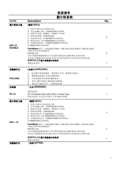
供货清单膜片钳系统Cat.No Description Qty 膜片钳放大器(德国HEKA)EPC-10 DOUBLE 1 双探头电脑全自动控制放大器。
2 具有Lockin功能,能精确测量膜电容测量。
3、钳制电压范围:±200mv,调幅最小为1mV4、钳制电流调整:±100nA/±2nA5、快速补偿电容:0-15pF(50G欧反馈电阻)5、慢补偿电容:0.2-1000pF(50G欧反馈电阻)6、全细胞反馈电容:1-255pF(1000M欧反馈电阻)3-1000pF(1M欧反馈电阻)1PatchMaster软件,多通道数据采集(8个A/D通道)与输出刺激(3个D/A输出通道)可输出多种多样的刺激波形P/N漏检功能具有全细胞和细胞贴附模式下进行膜电容测定的LOCK IN放大器的功能具有离子成像测定的扩展功能,扩展后可控制光源和对荧光测定进行控制的功能1IGOR Pro 5.0膜片钳数据分析软件数据分析软件 1显微操作仪(加拿大BURLEIGH)PCS-5400 1, 适合膜片钳实验操作,粗调部分手动,微调部分驱动;2,微操移动的最小步进为60纳米;3,压电晶体的形变范围300微米;4,带有与膜片钳放大器的探头适配器5,垂直水平旋转平台,方便更换电极1拉制器(日本NARISHIGE)PC-10 垂直拉制仪PC-10 Pipette Puller (220-240V): Vertical Type两步拉制仪,可以拉出尖端小于0.1um的电极1膜片钳放大器(德国HEKA)EPC-10 1 单探头电脑全自动控制放大器。
2 具有Lockin功能,能精确测量膜电容测量。
3、钳制电压范围:±200mv,调幅最小为1mV4、钳制电流调整:±100nA/±2nA5、快速补偿电容:0-15pF(50G欧反馈电阻)5、慢补偿电容:0.2-1000pF(50G欧反馈电阻)6、全细胞反馈电容:1-255pF(1000M欧反馈电阻)3-1000pF(1M欧反馈电阻)1PatchMaster软件,多通道数据采集(8个A/D通道)与输出刺激(3个D/A输出通道)可输出多种多样的刺激波形P/N漏检功能具有全细胞和细胞贴附模式下进行膜电容测定的LOCK IN放大器的功能具有离子成像测定的扩展功能,扩展后可控制光源和对荧光测定进行控制的功能1IGOR Pro 5.0膜片钳数据分析软件数据分析软件1显微操作仪(美国SUTTER)MP285 1 压电晶体技术驱动,精度60nm。
Invertek Drives Optidrive E3 变速器说明书

/optidrive-e3Offa’s Dyke Business ParkWelshpool, Powys, UKSY21 8JFTel: +44 (0)1938 556868Fax: +44 (0)1938 556869Email:************************INVERTEK DRIVES LIMITED UK HeadquartersGeneral Purpose DriveEasy control for all motor typesAbout Invertek DrivesSales, service & application support in over 80 countriesWorld-class production, innovation & training facilities at UK headquartersGlobal assembly cells controlled by cloud-based manufacturing databaseISO 14001 environmental &ISO 9001 quality management systemsAC Variable Speed DriveOptidrive E3L ow Power ApplicationsDedicated to low power applications, Optidrive E3 combines innovative technology, reliability, robustness and ease of use in a range of compact IP20 & IP66 enclosures.S imple Commissioning14 parameter basic setup. Default settings suitable for most applications. Contactor style connection for simple wiring.O ptidrive E3 IP66Environmentally protected, IP66 rated models can be mounted directly on your processing equipment.W ashdown ReadyWith a sealed ABS enclosure and corrosion resistant heatsink, Optidrive E3 IP66 models are ideal for high-pressure washdown applications.O n-drive ControlIP66 models feature optional, convenient controls for speed control, REV/OFF/FWD and Power ON/OFF, complete with safety lock.S ingle Phase Motor ControlOptidrive E3 for Single Phase Motors provides accurate speed control of single phase PSC or shaded pole motors. Specialboost phase ensures reliable starting, initially ramping the motor voltage up to rated voltage whilst maintaining a fixed starting frequency, before reducing the frequency and voltage to the desired operating point.+44 (0)1938 5568680.37kW – 37kW / 0.5HP – 50HP 110 – 480V Single & 3 Phase InputEasy to UseIP66IP20© 2019 I n v e r t e k D r i v e s L t d . A l l r i g h t s r e s e r v e d . 85-O D E 3B -I N V 2.16For worldwide locations, please visit /worldwide Contact your local representative at /representative Tel: 1-800-SM-CYCLO (762-9256)Operates up to 50°CCompact, robust and reliable general purpose drive for panel mountingSimply Power UpOptidrive E3 provides precise motor control and energy savings using the factorysettings. Simply power up and the drive can immediately deliver energy savings.14 basic parameters allow simple adjustment for your application if required, with up to 50 parameters available in total for a highly flexible performance.IP20Up to 37kWSimple InstallationDIN rail and keyhole mounting optionsQuick ReferenceIntegrated help cardOptistick SmartRapid commissioning toolSee Page 10Fast Connection5mm rising clamp terminalswith captive screws5 sizes cover global supply ratingsIncredibly Easy to UseBuilt in PI control, EMC filter (C1) & brake chopper Application macros for industrial, fan and pump operationconnectivityDual analogue inputsRTUon-board as standardControls Multiple Motor TypesIE2, 3 & 4IM, PM, BLDC and SynRMMotor supply connects at baseDust-Tight DesignInstall directly on your processing equipment and be sure of protection from dust and contaminants.Washdown ReadyWith a sealed ABS enclosure and corrosion resistant heatsink, the Optidrive E3 IP66 is ideal forhigh-pressure washdown applications.Switched modelsSimply wire up the drive, turn the inbuilt potentiometer and the motor will start running – allowing immediate energy savings.Saving energy cannot be easier than this!IP66/Nema 4X outdoor ratedBuilt with tough polycarbonate plastics specifically chosen to withstand degredation by ultra violet (UV), greases, oils and acids. Also robust enough not to be brittle at -20o C.For ultimate ease of useLockable Mains Disconnect / IsolatorLocal Speed Potentiometer Run Reverse / Off / Run Forward SwitchOutdoor rated enclosed drives for direct machine mounting, dust tight and ready for washdown dutyIP66 OutdoorUp to 22kWCoated Heatsink as StandardIdeal for hygiene based operations requiring washdown — such as food and beveragePower supply connects at top123Locally customisableFlat front to terminal cover with mounting points for switches and an internal PCB.2 x RJ45 portseliminate the need for a splitter.Easily accessible EMC disconnect Easy to wiredue to the large, accessible chamber and removeable gland plate.123Switched or non-switchedConformal coating as standardInput RatingsSupply Voltage 110 – 115V ± 10% 200 – 240V ± 10% 380 – 480V ± 10%SupplyFrequency48 – 62HzDisplacementPower Factor> 0.98PhaseImbalance3% Maximum allowedInrush Current< rated currentPower Cycles120 per hour maximum, evenly spacedOutput RatingsOutput Power 110V 1 Ph Input: 0.5–1.5HP (230V 3 Ph Output) 230V 1 Ph Input: 0.37–4kW (0.5–5HP)230V 3 Ph Input: 0.37–11kW (0.5–15HP)400V 3 Ph Input: 0.75–22kW460V 3 Ph Input: 1–30HPOverload Capacity 150% for 60 Seconds 175% for 2.5 secondsOutputFrequency0 – 500Hz, 0.1Hz resolution AccelerationTime0.01 – 600 seconds DecelerationTime0.01 – 600 secondsTypicalEfficiency> 98%Ambient Conditions Temperature Storage: −40 to 60°COperating: −20 to 50°CAltitudeUp to 1000m ASL without deratingUp to 2000m maximum UL approvedUp to 4000m maximum (non UL) Humidity95% Max, non condensing Vibration Conforms to EN61800-5-1Enclosure IngressProtection IP20, IP66Programming Keypad Built-in keypad as standardOptional remote mountable keypadDisplay7 Segment LEDPC OptiTools StudioControlSpecification ControlMethodSensorless Vector Speed ControlPM Vector ControlBLDC ControlSynchronous ReluctancePWMFrequency 4 – 32kHz EffectiveStoppingModeRamp to stop: User Adjustable 0.1 – 600 secsCoast to stopBraking Motor Flux BrakingBuilt-in braking transistor (not frame size 1)Skip Frequency Single point, user adjustableSetpointControlAnalogSignal0 to 10 Volts10 to 0 Volts0 to 20mA20 to 0mA4 to 20mA20 to 4mADigitalMotorised Potentiometer (Keypad)Modbus RTUCANopenEtherNet/IPFieldbusBuilt-inCANopen125–1000 kbpsModbusRTU9.6–115.2 kbps selectableI/O Specification Power Supply24 Volt DC, 100mA, Short Circuit Protected10 Volt DC, 10mA for PotentiometerProgrammableInputs4 Total2 Digital2 Analog / Digital selectableDigital Inputs8 – 30 Volt DC, internal or external supplyResponse time < 4msAnalog InputsResolution: 12 bitsResponse time: < 4msAccuracy: ± 2% full scaleParameter adjustable scaling and offsetProgrammableOutputs2 Total1 Analog / Digital1 RelayRelay Outputs Maximum Voltage: 250 VAC, 30 VDCSwitching Current Capacity: 6A AC, 5A DCAnalogOutputs0 to 10 VoltApplicationFeaturesPI Control Internal PI ControllerStandby / Sleep FunctionFire ModeBidirectionalSelectable Speed Setpoint (Fixed / PI / Analog/ Fieldbus)Maintenance &DiagnosticsFault Memory Last 4 Trips stored with time stampData LoggingLogging of data prior to trip for diagnosticpurposes:Output CurrentDrive TemperatureDC Bus VoltageMonitoring Hours Run MeterStandardsComplianceLow VoltageDirectiveAdjustable speed electrical power drive systems.EMC requirementsEMC Directive2014/30/EUCat C1 according to EN61800-3:2004MachineryDirective2006/42/ECConformance CE, UL, RCMDrive Specification2 221 110 150kW HP Amps Frame110 – 115V ± 10% 1 Phase Input 0.370.5 2.31ODE-3-110023-101#0.751 4.31ODE-3-110043-101#1.1 1.5 5.82ODE-3-210058-104#200 – 240V ± 10% 1 Phase Input 0.370.5 2.31ODE-3-120023-1#1#0.751 4.31ODE-3-120043-1#1#1.5271ODE-3-120070-1#1#1.5272ODE-3-220070-1#4#2.2310.52ODE-3-220105-1#4# 4515.33ODE-3-320153-104#200 – 240V ± 10% 3 Phase Input 0.370.5 2.31ODE-3-120023-301#0.751 4.31ODE-3-120043-301#1.5271ODE-3-120070-301#1.5272ODE-3-220070-3#4#2.2310.52ODE-3-220105-3#4# 45183ODE-3-320180-3#4# 5.57.5243ODE-3-320240-3#4# 7.510304ODE-3-420300-3#4# 1115464ODE-3-420460-3#4# 1520615ODE-3-520610-3F42 18.525725ODE-3-520720-3F42380 – 480V ± 10% 3 Phase Input 0.751 2.21ODE-3-140022-3#1#1.52 4.11ODE-3-140041-3#1#1.52 4.12ODE-3-240041-3#4#2.23 5.82ODE-3-240058-3#4#459.52ODE-3-240095-3#4#5.57.5143ODE-3-340140-3#4#7.510183ODE-3-340180-3#4#1115243ODE-3-340240-3#4#1520304ODE-3-440300-3#4#18.525394ODE-3-440390-3#4#2230464ODE-3-440460-3#4#3040615ODE-3-540610-3F423750725ODE-3-540720-3F42ProductFaModelCodeGenerationVoltageCoFrameSizeOutputCuSupplyPhaEnclosureBrakeTranEMCFilterEnclosure TypesEMC FilterAFB2Replace #colour-coded optionkW HP Amps Size110 – 115V ± 10%1 Phase Input0.370.571ODE -3-110070-1#1#-010.550.7510.52ODE -3-210105-1#4#-01200 – 240V ± 10%1 Phase Input0.370.5 4.31ODE -3-120043-1#1#-010.75171ODE -3-120070-1#1#-011.11.510.52ODE -3-220105-1#4#-01P r od uc tF a M od el C od eG en er a ti o nV o l t a g e C o F r a m e S i z e C a p a c i t y S u p p l y P h a E n c l o s u r e T S i n g l e P h a s B r a k e T r a n s E M C F i l t e r Enclosure TypesAB2Replace #colour-coded optionODE -3-120043-3F 12-01Product Family GenerationFrame Size Capacity 110–115V = 1Voltage Code 200–240V = 2380–480V = 4Model Code Guide:Drive SpecificationInput RatingsSupply Voltage 110 – 115V ± 10%200 – 240V ± 10%Supply Frequency 48 – 62Hz Displacement Power Factor > 0.98Phase Imbalance 3% Maximum allowed Inrush Current < rated currentPower Cycles120 per hour maximum, evenly spaced Output RatingsOutput Power 110V 1 Ph Input: 0.5–0.75HP230V 1 Ph Input: 0.37–1.1kW (0.5–1.5HP)Overload Capacity 150% for 60 Seconds 175% for 2.5 seconds Output Frequency 0 – 500Hz, 0.1Hz resolution Acceleration Time 0.01 – 600 secondsDeceleration Time 0.01 – 600 seconds Typical Efficiency> 98%Ambient ConditionsTemperatureStorage: −40 to 60°C Operating: −20 to 50°CAltitude Up to 1000m ASL without derating Up to 2000m maximum UL approved Up to 4000m maximum (non UL)Humidity 95% Max, non condensing VibrationConforms to EN61800-5-1EnclosureIngress Protection IP20, IP66ProgrammingKeypad Built-in keypad as standardOptional remote mountable keypad Display 7 Segment LED PCOptiTools StudioControl SpecificationControl Method V/F VoltageEnergy Optimsied V/F PWM Frequency 4 – 32kHz EffectiveStopping Mode Ramp to stop: User Adjustable 0.1 – 600 secs Coast to stopBraking Motor Flux BrakingBuilt-in braking transistor (frame size 2)Skip FrequencySingle point, user adjustableSetpoint ControlAnalog Signal0 to 10 Volts 10 to 0 Volts 0 to 20mA 20 to 0mA 4 to 20mA 20 to 4mADigital Motorised Potentiometer (Keypad)Modbus RTU CANopen EtherNet/IPFieldbusBuilt-inCANopen 125–1000 kbpsModbus RTU9.6–115.2 kbps selectableI/O SpecificationPower Supply 24 Volt DC, 100mA, Short Circuit Protected 10 Volt DC, 10mA for Potentiometer Programmable Inputs 4 Total 2 Digital2 Analog / Digital selectableDigital Inputs 8 – 30 Volt DC, internal or external supply Response time < 4msAnalog Inputs Resolution: 12 bits Response time: < 4ms Accuracy: ± 2% full scaleParameter adjustable scaling and offset Programmable Outputs 2 Total1 Analog / Digital 1 RelayRelay Outputs Maximum Voltage: 250 VAC, 30 VDCSwitching Current Capacity: 6A AC, 5A DC Analog Outputs 0 to 10 VoltApplication FeaturesPI Control Internal PI Controller Standby / Sleep FunctionFire Mode Selectable Speed Setpoint (Fixed / PI / Analog / Fieldbus)Maintenance & Diagnostics Fault MemoryLast 4 Trips stored with time stamp Data LoggingLogging of data prior to trip for diagnostic purposes:Output Current Drive Temperature DC Bus Voltage MonitoringHours Run MeterStandards ComplianceLow Voltage Directive Adjustable speed electrical power drive systems.EMC requirementsEMC Directive 2014/30/EU230V 1Ph. Filtered Units : Cat C1 according to EN61800-3:2004Machinery Directive 2006/42/EC ConformanceCE, UL, RCMPallet handling in UK Olive oil decanting in Greece Seed processing in NetherlandsPizza making in Belgium Chamfering machines in Italy Machine tool OEM in UKChemical fume removal in Singapore Sawmill optimisation in UK Precision polishing inSwitzerlandOptions & AccessoriesProven Worldwide in Low Power ApplicationsExternal EMC Filters, Input Chokes & Output Filters are availableSee for detailsCompatible with:Windows Vista & Windows 7, Windows 8, Windows 8.1 & Windows 10Drive commissioning and parameter backup• Real-time parameter editing • Drive network communication• Parameter upload, download and storage • Simple PLC function programming • Real-time scope function and data logging •Real-time data monitoringOptistick SmartRemote KeypadsRJ45 AccessoriesEtherNet ModuleOptiport 2Remote Keypad & LED DisplayOptipad Remote Keypad & TFT DisplayOptistick SmartRapid Commissioning Tool • Allows copying, backup and restore of drive parameters•Provides Bluetooth interface to a PC running OptiTools Studio or the OptiTools Mobile app on a smartphone •Onboard NFC (Near FieldCommunication) for rapid data transferOPT-2-OPORT-INOPT-3-OPPAD-INOPT-3-STICK-INEtherNet Module• ODVA compliant EtherNet/IP Modbus Translator Device• Compatible with all drive platforms: P2, E3 & Eco• Integrated network switch: simplifying network architecture •Compatible with RSLogix and CoDeSys PLCsBusiness-critical climate control for commercial horticulturist Hatziminas Flowers, GreeceChilled water pumpcontrol predicted to save AED 12385 per yearAl Jahili Fort, UAEEfficient water circulation gives energy savings of 60% per annum Leisure World, AustraliaChain wax development for Team Sky cycling team Muc-Off, UKCooling loop for solar energy research Solar Tech Lab, ItalyIdeal for simple and fast connection of Modbus RTU/CAN networksOPT-J4505-IN RJ45 Cable 0.5m OPT-J4510-IN RJ45 Cable 1.0m OPT-J4530-IN RJ45 Cable 3.0m OPT-J45SP-INRS485 3 Way Data Cable Splitter RJ45OPT-2-ETHEG-IN。
电工图标

85热电阻RT
86电位器RP
87电感(电抗)线圈L
88电流互感器TA CT或LH
89电压互感器TV PT或YH10KV电压互感器TV SYH 35KV电压互感器TV UYH 110KV电压互感器TV YYH
90断路器QF DL
91隔离开关QS G
92电力变压器TM B
93同步发电机GS TF
53自同期转换开关SSA2 ZTK
54自动开关QA
55刀开关QK或SN DK
56熔断器FU RD
57快速熔断器FUhs RDS
58闭锁开关SAL BK
59信号灯HL XD
60光字牌HL或HP GP
61警铃HAB或HA JL
62合闸接触器KMC HC
63接触器KM C
64合闸线圈Yon或LC HQ
65跳闸线圈Yoff或LT TQ
照明灯(发光器件) EL
空气调节器EV
电加热器加热元件EE
感应线圈,电抗器L
励磁线圈LF
消弧线圈LA
滤波电容器LL
电阻器,变阻器R
电位器RP
热敏电阻RT
光敏电阻RL
压敏电阻RPS
接地电阻RG
放电电阻RD
启动变阻器RS
频敏变阻器RF
限流电阻器RC
光电池,热电传感器B
压力变换器BP
温度变换器BT
速度变换器BV
66插座XS
67插头XP
68端子排XT
69测试端子XE
70连接片XB LP
71蓄电池GB XDC
72压力变送器BP YB
73温度变送器BT WDB
74电钟PT
75电流表PA
76电压表PV
77电度表PJ
InPro 8000 Series Turbidity Sensor 产品说明书

InPro 8000 Series Turbidity SensorFull range turbidity measurements Technical DataDimension drawing 2Specifications 3Ordering information4Accessories5Housings for InPro 8050, InPro 8100 and InPro 82006Short descriptionThis fiber optic measuring system is based on the backscattered light principle and consequently provides the highest possible performance from low/medium turbidities right through to high suspended particle concentrations.The InPro 8050 single optical fiber turbidity sensor utilizes a rugged polysulfone body and was developed specifically for accuracy and durability in the industrial waste water application.The InPro 8100 single optical fiber turbidity sensor is available in stainless steel and is intended for use in cell calture monitoring, pharmaceutical production and industrial processes. Autoclavable sensor is avail-able.The InPro 8200 dual optical fiber turbidity sensor is designed for use in cell calture monitoring, crystalliza-tion control and industrial processes including liquid/ solid separation. The InPro 8200 turbidity sensor is available in stainless steel or Hastelloy sensor body.Sensor features– Wide measuring range from 5/10 FTU up to 4000 FTU.– Small 12 mm sensor diameter, single/ dual optical fiber sensors made of polysulfone (PSU);DIN 1.4435 SS (316L) or Hastelloy (HA-C22) saves valuable space and for use in various application.– PG 13.5 threads for interface into various housing.– Various sensor lengths are available– Sterilizable and uniform sensor structure reduces fouling and the needs of sensor cleaningmaintenance.– Suitable for installation in classified area (Ex-proof).– for operation with METTLER TOLEDO M800 1-channel color touch screen transmitterContentsM800 1-channel transmitterInPro 8050InPro 8200InPro8100Dimension drawing InPro 8000 series turbdity sensor InPro 8050InPro 8100InPro 8200®-FDAAll dimensions in mm !Dimensions drawingsInPro 8000 Series Turbidity SensorSpecifications InPro 8000 series turbdity sensorSensor material PSU (Polysulfone)DIN 1.4435 (316L)Din 1.4435 (316L) or HA-C22 Sensor diameter12 mm12 mm12 mmInsertion length120 mm120, 205, 297 or 407 mm120, 205, 297 or 407 mm Process connection Pg 13.5Pg 13.5 Pg 13.5Measuring range:Formazin Turbidity Units10…4000 FTU10…4000 FTU5…4000 FTUSuspended Solids(Diatomaceous earth as reference)0…250 g/L0…250 g/L0…30 g/LDesign:Cable connectors SMA SMA SMACable lengths 6 m (20 ft) optical 3 m (10 ft) optical 3 m (10 ft) opticalCable type duplex HCS fiber, fixed duplex HCS fiber, fixed duplex HCS fiber, fixed Wetted parts:Metals none DIN 1.4435 (316L)DIN 1.4435 (316L)or Hastelloy (HA-C22) Plastic PSU none noneO-ring Viton®-FDA Viton®-FDA Viton®-FDASapphire spigotfor fiber protectionyes none noneSapphire window for fiber protection none none Kalrez®-type:Kalrez®-FDA 6230 sealedEpoxy-type:Epoxy bondedWorking conditions:Pressure range 0…2 bar (0…29 psi)0…6 bar (0…87 psi)Epoxy-type:0…16 bar (0…232 psi)With Swagelok® adapter:60 bar (0…870 psi)Kalrez®-type:0…6 bar (0…87 psi)Measuring temperature range0…60 °C(32…140 °F)– 30…130 °C(– 22…266 °F)Epoxy-type:– 30…130 °C (– 22…266 °F)Kalrez®-type:–10…130 °C (14…266 °F)Temperature range (sterilization)n/a0…130 °C(32…266 °F)Kalrez® -type:0…130 °C (32…266 °F) Epoxy type:n/aCertificate and Approval:n/a x Ex II 1/2G Ex op is/op pr IIA95 °C Ga/Gbx Ex II 1/2G Ex op is/op pr IIB38 °C Ga/Gbx Ex II 1/2G Ex op is/op pr IIA 95 °C Ga/Gbx Ex II 1/2G Ex op is/op pr IIB 38 °C Ga/GbSpecifications InPro 8000 Series Turbidity SensorSpecifications /Ordering Information InPro 8000 Series Turbidity Sensor Specifications duplex fiber optic cableCladding material HCS (Hard Clad Silica)Core diameter600 ±10 µmAttenuation @ 850 nm≤ 8 dB/kmLong-term bend radius≥ 94 mmOuter jacket PVCOrdering informationDesignation code InPro 8100/S/xxx S = shaft materialDIN 1.4435 (316L)InPro 8200/S(H)/...../xxx H = Hastelloy C22..... = sealing for sapphire windowxxx = insertion length in mmInPro 8100/S/120120 mm (4.7")DIN 1.4435 (316L)52 800 205InPro 8100/S/205205 mm (8.1")DIN 1.4435 (316L)52 800 206InPro 8100/S/297297 mm (11.7")DIN 1.4435 (316L)52 800 207InPro 8100/S/407407 mm (16.0")DIN 1.4435 (316L)52 800 208InPro 8200/S/Epoxy/120120 mm (4.7")DIN 1.4435 (316L)52 800 216InPro 8200/S/Epoxy/205205 mm (8.1")DIN 1.4435 (316L)52 800 217InPro 8200/S/Epoxy/297297 mm (11.7")DIN 1.4435 (316L)52 800 218InPro 8200/S/Epoxy/407407 mm (16.0")DIN 1.4435 (316L)52 800 219InPro 8200/H/Epoxy/120120 mm (4.7")HA-C22 (Hastelloy)52 800 220InPro 8200/H/Epoxy/205205 mm (8.1")HA-C22 (Hastelloy)52 800 221InPro 8200/H/Epoxy/297297 mm (11.7")HA-C22 (Hastelloy)52 800 222InPro 8200/H/Epoxy/407407 mm (16.0")HA-C22 (Hastelloy)52 800 223InPro 8200/S/Kalrez-FDA/120120 mm (4.7")DIN 1.4435 (316L)52 800 224InPro 8200/S/Kalrez-FDA/205205 mm (8.1")DIN 1.4435 (316L)52 800 225InPro 8200/S/Kalrez-FDA/297297 mm (11.7")DIN 1.4435 (316L)52 800 226InPro 8200/S/Kalrez-FDA/407407 mm (16.0")DIN 1.4435 (316L)52 800 227Accessories InPro 8000 Series Turbidity Sensor AccessoriesFiber optic extension 5 m 5 m (15 ft)52 800 229Fiber optic extension 6 m 6 m (18 ft)52 800 230Fiber optic extension 10 m10 m (30 ft)52 800 231Fiber optic extension 15 m15 m (45 ft)52 800 232Fiber optic extension 20 m20 m (60 ft)52 800 233Fiber optic extension 25 m25 m (75 ft)52 800 234Fiber optic extension 30 m30 m (100 ft)52 800 235Fiber optic extension 75 m75 m (230 ft)52 800 177Fiber optic extension 100 m100 m (330 ft)52 800 15452 800 240Couplings(2 included in each fiber kit)Coupling Box IP 65/NEMA 4X52 800 241Swagelok adapter NPT 1/2"52 800 242“CaliCap” (calibration tool)52 800 210O-ringsViton-FDA 10.77 x 2.62 mm59 905 680Silicon-FDA10.77 x 2.62 mm59 905 678Kalrez®-FDA10.78 x 2.62 mm59 905 789EPDM-FDA10.77 x 2.62 mm59 905 768TransmitterM800, 1-channel 30 026 633Housings InPro 8000 Series Turbidity SensorHousings for InPro 8050Insertion InFit761/NS/0070/PP__/D00/Vi9-PP70120DN25Viton®-FDA52 400 316 Open Basin InDip550/1000 PVC Pg13.5PVC1000120N/A Viton®-FDA52 400 320 InDip550/1500 PVC Pg13.5PVC1500120N/A Viton®-FDA52 400 582InDip550/2000 PVC Pg13.5PVC2000120N/A Viton®-FDA52 400 588InDip550/2500 PVC Pg13.5PVC2500120N/A Viton®-FDA52 400 594InDip550/3000 PVC Pg13.5PVC3000120N/A Viton®-FDA52 400 600 Housings for InPro 8100 and InPro 8200Insertion InFit761/WS/0070/4435/D10/Vi2-DIN 1.443570120DN25Viton59 900 753 InFit761/NS/0070/4435/D00/Si9-DIN 1.443570120DN25Silicon-FDA59 900 796 InFit761/NC/0070/4435/D00/Si9-DIN 1.443570120DN25Silicon-FDA52 400 491 InFit761/NC/0033/4435/V02/Si-DIN 1.443533120Varivent Silicon-FDA52 400 502 InFit761/NC/0070/4435/T01/Si-DIN 1.443570120TC 1.5"Silicon-FDA52 400 494 InFit761/NC/0070/4435/T02/Si-DIN 1.443570120TC 2"Silicon-FDA52 400 495Retractable from the process InTrac779M/070/4404/D00/Vi/A00DIN 1.440470205DN25Viton®-FDA52 403 236 InTrac799M/100/4404/D00/Vi/A00DIN 1.4404100297DN25Viton®-FDA52 403 237Note: Please consult your local METTLER TOLEDO representative for more option.Notes:9001certifiedISO14001certifiedISO。
Parker Hannifin Corporation 零温度方向控制阀Viking系列P2L-A、
Directional Control ValvesLow Temperatu re Viking SeriesP2L-A, 1/8 - 27 NPTFP2L-B, 1/4 - 18 NPTFP2L-D, 1/2 - 14 NPTFCatalog 0677!WARNINGFAILURE OR IMPROPER SELECTION OR IMPROPER USE OF THE PRODUCTS AND/OR SYSTEMS DESCRIBED HEREIN OR RELATED ITEMS CAN CAUSE DEATH, PERSONAL INJURY AND PROPERTY DAMAGE.This document and other information from Parker Hannifin Corporation, its subsidiaries and authorized distributors provide product and/or system options for further investigation by users having technical expertise. It is important that you analyze all aspects of your application including consequences of any failure, and review the information concerning the product or system in the current product catalog. Due to the variety of operating conditions and applications for these products or systems, the user, through its own analysis and testing, is solely responsible for making the final selection of the products and systems and assuring that all performance, safety and warning requirements of the application are met.The products described herein, including without limitation, product features, specifications, designs, availability and pricing, are subject to change by Parker Hannifin Corporation and its subsidiaries at any time without notice.Offer of SaleThe items described in this document are hereby offered for sale by Parker Hannifin Corporation, its subsidiaries or its authorized distributors. This offer and its acceptance are governed by the provisions stated on the separate page of this document entitled “Offer of Sale”.© Copyright 2004, Parker Hannifin Corporation. All Rights Reserved.2Directional control valvesVikingSummary Page General information (5)Order key (6)Flow characteristics (7)Technical data............................................................................................7-8 Main data, pneumatically actuated.. (9)Dimensions, pneumatically actuated.......................................................10-11 Main data, electrically actuated, complete valves for 24 V AC/DC. (12)Main Data, electrically actuated (supplied without solenoid valves) (13)Dimensions, electrically actuated............................................................14-15 Main data, hand operated, lever 90° to ports (16)Dimensions, hand operated, lever 90° to ports........................................17-18 Main data, hand operated, lever in line with ports.. (19)Dimensions, hand operated, lever in line with ports (20)Main data, hand operated, manual locking (21)Dimensions, hand operated, manual locking (22)Solenoid valves order key (23)Solenoids 15mm NC, mobile (24)Cable plugs (25)Solenoid dimensions (26)Offer of sale (27)Conversion factors1 kg= 2.2046 lb1 N= 0.22481 lbf1 bar= 14.504 psi1 l= 0.21997 UK gallon1 l= 0.26417 US gallon1 cm3= 0.061024 in31 m= 3.2808 feet1 mm= 0.03937 in9/5 °C + 32 = °F34Directional control valvesVikingThe Viking valve range is robust, versatile and combines high performance with compact installation dimensions. Large flow capacity, short change-over times and low change-over pressure are important characteristics of this valve range.Viking valve rangeP2L-A, dimension 1/8 - 27 NPTF, P2L-B, dimension 1/4 - 18 NPTF, P2L-D, dimension 1/2 - 14 NPTFThe P2L-A, P2L-B and P2L-D have a wide range of hand, foot,pneumatic and electrically operated valves in both 5/2 and 5/3configurations.The Viking range is available in both standard and low temperature versions.5Directional control valvesVikingCompact dimensions, direct body porting and integral mounting holes are all features of the Viking range In addition to simple single installation, the Viking range may be installed in very compact blocks.Rust and corrosion resistant designs.Viking valves are made entirely of anodized aluminium, forcorrosion resistance. The smooth design, with no dirt-collecting pockets, makes the valve suitable for most environments,including applications with stringent hygiene requirements. The valve has stainless steel screws for the end covers, to withstand aggressive environments.Mobile applicationsCommission and service is facilitated by the generously sized,ergonomically designed buttons for manual operation on the P2L-B valve range, which are a standard feature. These make it very easy to see the valve spool position during fault finding.A wide range of solenoid valvesA robust anodized aluminium valve housing, standard and low-temperature versions, hand lever with built-in catch for reliable retention in position, variants designed for a special NO (normally open) mobile solenoid valve, and several varieties of specialmobile (NC) solenoid valves make the valve an excellent choice in mobile applications.High reliabilityManual override - indication on the P2L-BA number of different versions of our solenoid valves P2E with 15 mm DIN 43650 form C enclosures are available to suit justabout any application. The valve has small installation dimensions,low energy consumption, large flow diameter, large flow capacity,a robust valve body, high reliability and long service life. With or without flush locking, extended non locking manual override, with long or short arm, spring biased or indexing.Low noise levelThe exhaust air from the pilot valves is exhausted through a silencer located in the end cover or body, to give the lowest possible noise level. This is particularly important for industries where low noise levels are required. The silencers make it possible for the valves to comply with the EU Machinery Directive,Noise 1.5.8.CertificationThe solenoid valves are protection class IP65 with the standard cable plug. The cable plug with reinforced protection raises the protection standard to IP67.Several types of cable plugsCompact installation dimensions - flexible installationValves easily comply with the requirements for componentreliability in accordance with the EU Machinery Directive standards EN292-2 and EN983.In the P2L-A: few moving parts combined with short spoolmovement give a valve with high reliability and long service life. It is designed for use with, or without supplementary lubrication.In the P2L-B and P2L-D: high molecular weight plastics with self-lubricating properties make it suitable for use with, or without supplementary lubrication.MaintenanceSize A and B spare parts = new valve.With or without suppression, LED and rectifier. For connection to your own cables or with molded cable. A large selection allows you to choose cables to meet your requirements.Insensitive to dirty airThanks to large flow passage areas and the large flow diameter of 1.0 in the pilot valves, the P2L-A, P2L-B and P2L-D can be used in normal industrial or mobile environments without any problems of sticking. However, the service life of the valve depends on thecleanliness of the air. Please refer to ISO 8573.Directional control valves Viking Order key67Flow characteristicsFlow capacities in accordance with ISO6358.All pressures = effective pressureThe curves in the diagram below are typical only.P2L-AP2L-BDirectional control valvesVikingP2L-DTechnical dataP2L-ADimension1/8 - 27 NPTFOperating pressure, max 145 psi (10 bar)* Also see “Operating pressure”.Operating temperature range for directional control valves low temp. version-40 to 86 °F (–40 to +30 °C)Operating temperature range for P2E solenoid valves mobile version -40 to 158 °F (–40 to +70 °C)FlowCv=0.76(Flow acc. to ISO 6358)(C=3,0 Nl/s x bar)(b=0.3)(Qn=12.7 l/s)(Qmax=21.0 l/s)P2L-BDimension1/4 - 18 NPTFOperating pressure, max 145 psi (10 bar)* Also see “Operating pressure”.Operating temperature range for directional control valves low temp. version-40 to 86 °F (–40 to +30 °C)Operating temperature range for P2E solenoid valves mobile version -40 to 158 °F (–40 to +70 °C)FlowCv=1.0(Flow acc. to ISO 6358)(C=4.2 Nl/s x bar)(b=0.2)(Qn=17.0 l/s)(Qmax=29.4 l/s)P2L-DDimension1/2 - 14 NPTFOperating pressure, max 145 psi (10 bar)* Also see “Operating pressure”.Operating temperature range for directional control valves low temp. version-22 to 86 °F (–30 to +30 °C)Operating temperature range for P2E solenoid valves mobile version -40 to 158 °F (–40 to +70 °C)FlowCv=2.9(Flow acc. to ISO 6358)(C=12 Nl/s x bar)(b=0.2)(Qn=48.0 l/s)(Qmax=84.0 l/s)3003x1056006x1059009x105120012x105150015x105180018x105210021x105Flow [l/s][l/min][Sccm]6001200180024003000[l/min]Flow[l/s]6x10512x10518x10524x10530x105[Sccm]1200240036004800600072008400[l/min]Flow[l/s]12x10524x10536x10548x10560x10572x10584x105[Sccm]8Material specificationP2L-A ValveValve body Anodized aluminium End coversAnodized aluminium or Reinforced thermoplasticLever housing Acetal plastic Spool Aluminium + nitrile rubber Piston Acetal plastic/ Anodized aluminium U-rings, O-rings Nitrile rubber End cover sealings Nitrile rubber End cover screws Stainless steel Springs Dacromet® - processed steel,Stainless steelLever Reinforced polyamid plastic Panel mounting nut Polycarbonate plastic Gaiter Chloroprene rubber Mounting screws for solenoid Stainless steelP2L-B ValveValve body Anodized aluminium Spool Acetal plastic/ Anodized aluminiumPistonAcetal plastic /Anodized aluminiumLiningReinforced thermoplastic End covers Anodized aluminium Sliding seals Thermoplastic U-rings, O-rings Nitrile rubber End cover sealings Nitrile rubberPush button for manual changeoverAcetal plastic End cover screws Stainless steel Springs Stainless steel LeverZinc-plated steel Catch for lever Stainless steelKnob Phenolic plastic/Anodized aluminium Gaiter Chloroprene rubber Foot pedalAluminiumMounting screws for solenoidZinc-plated steelDirectional control valvesVikingP2L-D ValveValve body Anodized aluminium Spool Anodized aluminium Piston Brass LiningBrassEnd covers Anodized aluminium Sliding seals Thermoplastic U-rings, O-rings Nitrile rubber End cover sealings Nitrile rubber End cover screws Stainless steel Springs Stainless steel LeverStainless steel Catch for lever Zinc-plated steel Knob Thermoplastic GaiterNitrile rubber Distance ringThermoplasticMounting screws for solenoidZinc-plated steelDimensions* Operating pressureFrom 0 to 145 psi (10 bar) connectable in all portsThis is valid with the following exceptions:Electrically actuated valves•If supply pressure is connected to any other port than port 1 [port 1 also provides supply pressure to solenoid(s)] or if the air supply pressure is lower than minimum signal pres-sure it is necessary to use valves with external air supply to solenoid(s。
IP 系列单相逆变器操作说明书
IP系列单相逆变器操作说明书迅昌电气(上海)有限公司CINTRONG ELECTRICITY(SHANGHAI)CO.,LTD.苏州迅昌电力电子有限公司SUZHOU CINTRONG POWER ELECTRONICS CO.,LTD.重要提示:该设备符合以下参考标准IEC60950-1,IEC62040-1-1使用操作区一般安全IEC/EN62040-2EMC要求IEC62040-3性能要求和测试方法设备的安装应遵照以上要求并使用厂家指定附件。
本手册涉及IP工频逆变电源的相关安装与运行资料,请在安装前详细阅读本手册。
该设备内部有整流滤波电容,是储能元件,在关断输入交流电源后,直流部分可能仍有电压,请注意人身安全。
该设备安装有射频干扰(RFI)滤波器。
对地漏电流在3.5mA~1000mA之间。
在选择瞬变漏电流断路器(RCCB)或其它漏电检测仪器(RCD)时应考虑设备启动时可能出现的瞬态和稳态对地漏电流。
必须选择对单向直流脉冲(A级)和瞬态电流脉冲不敏感的RCCB。
请注意负载的对地漏电流也将流过RCCB或RCD。
目录1产品介绍 (1)1.1概述 (1)1.2设计思想 (1)1.3产品特点 (2)2搬运放置 (2)3使用环境 (2)4安装说明 (3)4.1初检 (3)4.1产品外形图 (3)5电气原理图(仅供参考) (4)6参数说明 (5)7电气连接 (5)8操作说明 (6)8.1准备开机 (6)8.2开机过程 (6)8.3关机过程 (6)9LCD说明 (6)9.1按键说明 (6)9.2参数显示 (7)10故障检修 (7)申明该手册仅适用于IP系列工频逆变电源产品,属通用版本。
技术指标详见技术合同或产品铭牌。
1产品介绍1.1概述IP工频逆变电源是迅昌公司采用ARM新一代32位处理器为核心,IGBT为执行元件,隔离变压器进行电压转换设计而成。
IP工频逆变电源采用DC-AC(直流-交流)的方式通过SPWM(正弦波脉宽调制)变换将输入电源转换成世界任何电源,以满足不同电压、不同频率的需要。
霍尼韦尔楼宇自控产品应用手册

--
13、 N20,N34系列20Nm,34Nm风门执行器…………………………………………………………………………………………………82 14、 S05, S10, S20系列5Nm,10Nm,20Nm弹簧复位风门执行器………………………………………………………………… 83
四 、控制阀门
1 、 V4043, V4044风机盘管电动阀 ( 弹簧复位 )………………………………………………………………………………………… 84 2 、 VC系列二通及三通风机盘管电动阀…………………………………………………………………………………………………… 86 3 、 V5011P二通螺纹线性阀门PN16……………………………………………………………………………………………………… 91 4 、 V5013P三通螺纹线性阀门PN16………………………………………………………………………………………………………96 5 、 V5011N, P, F, G二通螺纹线性阀门PN16…………………………………………………………………………………………… 101 6 、 V5013N,P三通螺纹线性阀门PN16……………………………………………………………………………………………………102 7 、 V5211F高关断力二通螺纹线性阀门 PN16…………………………………………………………………………………………… 103 8 、 V5328A法兰型二通线性阀门PN16…………………………………………………………………………………………………… 104 9 、 V5088A 高关断力法兰型二通线性阀门PN16……………………………………………………………………………………… 105 10、 V5329A/V5050A.B法兰型三通线性阀门PN16……………………………………………………………………………………… 106 11、 V5016A二通法兰线形阀门PN16……………………………………………………………………………………………………… 107 12、 V5025A二通法兰线形阀门PN25……………………………………………………………………………………………………… 108 13 、V5049A.B法兰型二通线性阀门PN25/40………………………………………………………………………………………………109 14、 V5050A.B法兰型三通线性阀门PN25/40………………………………………………………………………………………………110 15 、V5832A/V5833A.C小线形调节、开关阀门PN16…………………………………………………………………………………… 111 16 、V5431A.F三通旋转阀门PN6……………………………………………………………………………………………………………113 17 、V5433A三通旋转阀门PN6………………………………………………………………………………………………………………114 18 、V4系列电动蝶阀……………………………………………………………………………………………………………………… 115 19 、大线性阀与执行器匹配表………………………………………………………………………………………………………………120 20 、旋转阀与执行器匹配表…………………………………………………………………………………………………………………124 21 、Cv值的计算………………………………………………………………………………………………………………………………126
IC库存表

SOP SOP SOP SOP SOP SOP SOT SOP TSSOP SOP SOP SOP SOP SOP SOP-14 SOP SOP SOP SOP SOP SOP SOT23-5 SOT23-5 SC70-5 SOT-353 SOT-353 SOT-353 SOT-353 SOT23-5 SOT23-5 SOP SOP SOP TSSOP SOP SOP TSSOP SOT-363 SOT-353 SOP TSSOP SOP TSSOP SOT-353 SOT-153 SOT-23 TSSOP
NXP NXP NXP NXP NXP NXP NXP NXP NXP NXP NXP NXP NXP NXP NXP NXP NXP NXP NXP NXP NXP NXP NXP NXP NXP NXP NXP NXP NXP NXP NXP NXP NXP NXP NXP NXP NXP NXP NXP NXP NXP NXP NXP NXP NXP NXP NXP
NXP NXP NXP NXP NXP NXP NXP NXP NXP NXP NXP NXP NXP NXP NXP NXP NXP NXP NXP NXP NXP NXP NXP NXP NXP NXP NXP NXP NXP NXP NXP NXP NXP NXP NXP NXP NXP NXP NXP NXP NXP NXP NXP NXP NXP NXP NXP
11+ 11+ 11+ 11+ 11+ 11+ 11+ 11+ 11+ 11+ 11+ 11+ 11+ 11+ 11+ 11+ 11+ 11+ 11+ 11+ 11+ 11+ 11+ 11+ 11+ 11+ 11+ 11+ 11+ 11+ 11+ 11+ 11+ 11+ 11+ 11+ 11+ 11+ 11+ 11+ 11+ 11+ 11+ 11+ 11+ 11+ 11+
K-LB-1.30G

K-LB-1.30G
端子 1, 2; 7, 8 ≤30 V ≤250 mA ≤5 µA ≤45 V 500 V 击穿电压力
PTB 00 ATEX 2176X, 其它证书见
¬ II 2 (1) G EEx ia IIC T6
Ui
30 V
Ii
250 mA
g 8
Sensor 7
u 2 1
u
g
28
17
u = 非保护区域 g = 保护区域
使用时接地
Date of issue 03.07.2002
不保证样本内容毫无差错,样本内容更改时恕不通知
德国P+F集团 版权所有
上海倍加福 电话:上海(021)56525989(总机) 传真:(021)56527164 网址:www.pepperl-fuchs.com
PTB 00 ATEX 2176X, 其它证书见 ¬ II 2 (1) G EEx ia IIC T6
30 V 250 mA 0 nF 200 µH 10 kA (8/20 µs) 符 合 IEC 60-2
1 ns 100 ns
每根导线 < 0.3欧 ≥40KHZ
241
机械结构 外形尺寸
12.5 x 115 x 110 mm (0.5 x 4.5 x 4.3 inch)
注意
浪涌保护器必须可靠接地(粗线,接线短)。这是有效保护的基本要求。
K-LB-o.30G
K-LB-2.30G
端子 1, 2; 7, 8/3, 4; 5, 6 ≤30 V ≤250 mA ≤5 µA ≤45 V 500 V 击穿电压力
0 nF
200 µH
10 kA (8/20 µs) 符 合 IEC 60-2
Autonics SPR1系列单相薄型电源控制器说明书

TCD210146AC_MODISingle-Phase Slim Power ControllersSPR1 SeriesCATALOGFor your safety, read and follow the considerations written in the instruction manual, other manuals and Autonics website.The specifications, dimensions, etc. are subject to change without notice for product improvement. Some models may be discontinued without notice.• Slim and elegant design• LED display allows real-time monitoring of control input, load voltage, load current, load power, load resistance, and heat-sink temperature• Stable control with feedback control (constant current, constant voltage, constant power)• Communication output models available: RS485 (Modbus RTU)• Parameter configuration via PCs (RS485): Free device management software (DAQMaster)• Various alarm functions (alarm output) : over current, over voltage, heater disconnection, fuse break, heat-sink over heat, diode (SCR) error • Easy installation with mounting brackets • Easy fuse replacement and maintenance• High performance SCR (IXYS) diodeᜢ■DAQMasterIt is the comprehensive device management program for Autonics' products, providingparameter setting, monitoring and data management.For selecting the specified model, follow the Autonics website. SPR1-❶❷❸❹❺❶ Rated load voltage 1: 110 VACᜠ2: 220 VACᜠ3: 380 VACᜠ4: 440 VACᜠ❹ Feedback controlN: Normal control F: N ormal, feedback control (constant current / constant voltage / constant power) ❷ Rated load currentNumber: Rated load current (unit: A)❺ Fuse N: NoneF: Supports fuse❸ Option output N: Alarm output T: A larm output + RS485 comm. output■■■18, Bansong-ro 513Beon-gil, Haeundae-gu, Busan, Republic of Korea, |+82-2-2048-1577|******************Rated load current 25 A Rated load current 35 AL o a d c u r r e n t [A ]2515201050010203040506070Ambient temp.[℃]3521281470010203040506070L o a d c u r r e n t [A ]Ambient temp.[℃]■Rated load current 50 A■Rated load current 70 AL o a d c u r r e n t [A ]Ambient temp.[℃]5030402010001020304050607025L o a d c u r r e n t [A ]Ambient temp.[℃]7042562814001020304050607035 ■Rated load current 100 A ■Rated load current 150 ALo a d c u r r e n t [A ]Ambient temp.[℃]100608040200010203040506070L o a d c u r r e n t [A ]Ambient temp.[℃]150901206030001020304050607001. Bracket RUN mode: Displays depending the front display settingSetting mode: Displays parameter and setting value in setting mode 04. U nit indicator (V, A)Enters parameter group, returns to RUN mode, moves parameters, and saves the setting value.Enters SV setting mode and move digits.07. Output control adjuster (OUT ADJ)Adjusts output from 0 to 100 % in manual control.08. C ontrol input / comm. outputterminal (11-pin connector terminal)09. Terminal protection cover 10. A larm output / power inputterminal11. R, S, U load output terminal 12. Cooling fan[Rated load current 70 / 100 / 150 A model] 13. Heatsink14. Bolt for grounding (M4)。
布什安全设备D7050DH多路照电漏温传感器安装指南说明书
NoticesThese instructions cover the installation of theD7050DH Multiplex Photoelectric Duct Smoke Detector on a D7024 or a DS9400M 24 VDC Fire Alarm Control Panel (FACP) with a D7039 or DS9431 Multiplex Expansion Module installed. The D7024 and DS9400M requires ROM version 2.0 or greater. Install, test, and maintain the D7050DH according to these instructions, NFPA 72, local codes, and authority having jurisdiction (AHJ).Follow the procedures in these instructionsto avoid personal injury and damage to theequipment. Failure to follow theseinstructions can result in the D7050DH notoperating properly. Bosch is notresponsible for improperly installed, tested,or maintained devices.The D7050DH complies with Part 15 of the Federal Communications Commission (FCC) Rules and with the RSS-210 of Industry and Science Canada.D7050DH operation is subject to the following two conditions:1.It does not cause harmful interference.2.It must accept any interference it receives,including interference that might cause undesirable operation.1.0 DescriptionThe D7050DH (Figure 1) is Underwriters Laboratories, Inc. (UL) Listed and requires a D343 Duct Detector Housing. Use this detector with the D7024 or aDS9400M that includes a D7039 or DS9431 Multiplex Expansion Module.An LED indicator on the head flashes every 3 to 8 sec to ensure the D7050DH has power and the smoke sampling circuitry functions. This LED flashes at least once each second during an alarm confirming individual detector alarms. The D7050DH automatically resets after the alarm condition clears. 2.0 InstallationFor installation details, refer to the D7024 FACP Operation and Installation Guide (P/N: 31499), theD9400M Reference Guide (P/N: 44578), the D7039 Installation Guide (P/N: 38685), or the D S9431 Installation Instructions (P/N: 41381).Table 1: Maximum Wire Length Allowed foreach Multiplex BusWire Gauge Maximum 50 Ω for eachBus Loop18 AWG (1.02 mm) 3800 ft (1170 m)16 AWG (1.29 mm) 5950 ft (1810 m)14 AWG (1.63 mm) 5950 ft (1810 m)12 AWG (2.05 mm) 5950 ft (1810 m)Table 2: Maximum Number of DetectorsAllowed for each Multiplex BusWith Remote Test 40With Remote LED 50Without Annunciator 703.0 Wiring the D343You can wire the D343 in series as shown in Figure 2.4.0 Setting the AddressSet the D7050DH’s address using a flat-blade screwdriver to position the rotary switches(Figure 3) located on the back. Note that the switches click when turned.The valid address range is from 009 to 255. Refer to the D7024 Operation and Installation Guide (P/N: 31499) or the DS9400M Reference Guide (P/N: 44578) for additional address limitations.Figure 3 shows the A address range set at 095, allowing the D7039 to work with the D7024 FACP.5.0 Mounting1. Remove the tamper screw located in the recesson the top of the dust cover. 2. Remove the dust cover.3. Mount and wire the duct housing according to theD343 Installation Instructions (P/N: 48199). 4. Mount the D7050DH to the base by turning itclockwise until it clicks into place (Figure 4).6.0 ProgrammingFor multiplex programming, refer to the D7024 FACP Operation and Installation Guide (P/N: 31499)or theDS9400M Reference Guide (P/N: 44578).7.0 TestingTest detection devices immediately after installation. Test the D7050DH according to NFPA Chapter 7-1.6.2 (1999) or more often as required by local code.7.1 OperationalTesting2.If a D7050DH is in alarm, shut down the system.3.Remove the D7050DH and recheck for properwiring. If the problems persist, replace the affected D7050DH or exchange it with a known gooddetector. This determines if the problem is caused by the D7050DH.4.When the system is free of alarms, check eachD7050DH to ensure the red LED indicator on the head flashes. This confirms the detector isoperating properly.5.Test each D7050DH to ensure it causes a controlpanel alarm.6.Alarm the D7050DH by doing one of thefollowing:a.Place a magnet horizontally against the recessin the duct cover, centering it over the “T”marked on the head to activate an internalreed switch.b.Remove the duct cover and use a UL Listedaerosol smoke detector tester such as theHome Safeguard Industries’ 25S to simulatean alarm. Follow the instructions included inthe aerosol smoke detector tester.7.When a D7050DH alarms, the red LED indicatoron the head flashes at least once per second. Clear the alarm by initiating a system reset beforeproceeding to the next detector. 7.2 SensitivityTestingTest the D7050DH’s sensitivity to meet NFPA 72 requirements by conducting a Magnet Test (refer to Section 7.3 Magnet Test). You can also test sensitivity by measuring the calibration voltage pins with D1005 Test Cable, D344-RL, or D344-RT (refer to Section 7.4 Voltage Measurement Test). Calibration can be quickly determined by visually inspecting the D7050DH’s LED (refer to Section 7.2.2 Visual Check). These tests confirm whether or not the detector is within its factory marked calibration range.7.2.1 SensitivityTestThe control panel constantly monitors the D7050DH. If the detector exceeds the limits of the sensitivity thresholds, the control panel reports the detector in question and generates a fault condition.7.2.2 VisualCheckThe D7050DH includes the Chamber Check Automatic Trouble Indication that allows it to automatically show if its calibration is out of the factory-listed range. You can meet the NFPA guidelines for sensitivity testing by visually inspecting theD7050DH and checking the Alarm LED flash rate.If the calibration is out of range during power up or longer than 24 h, the Alarm LED double flashes. This LED single flashes when the detector is operating7.3 MagnetTestthe D343 cover for approximately 10 sec.2.Observe the LED. If the D7050DH is within thefactory marked calibration range, it goes into alarm and the Alarm LED flashes at least once persecond.a.If the D7050DH is too sensitive, the AlarmLED flashes six times rapidly (once every 0.5sec) and the detector goes into alarm.b.If the D7050DH is not sensitive enough, theAlarm LED flashes four times slowly (onceevery 2 sec) and the detector goes into alarm.3.If the D7050DH is not operating, it does not signalan alarm. Return the detector for repair.7.4 Voltage Measurement Test1.Plug a D1005 Test Cable (optional) into thecalibration voltage pin.2.Connect a digital voltmeter to the D1005.3.Connect the voltmeter’s negative terminal to theblack wire on the D1005 and connect the positiveterminal to the red wire. The white wire is notused.4.If a D344-RL or D344-RT is installed, use thevoltage monitor jacks as described below:a.The voltage measured by the voltmeter is halfthe sensitivity (in %/ft obscuration) of theD7050DH.b.Multiply the voltage by 2. The result must bewithin the factory-marked calibration rangeprinted on the label located on the bottom ofthe D7050DH.c.If the D7050DH is outside the factory-markedcalibration range, remove it and clean it. Orreplace it as described in Section 7.1OperationalTesting.d.After cleaning, recheck the calibration voltagemeasurement. If the D7050DH is still outsideof the factory-marked calibration range, returnit for recalibration to:National Repair Center130 Perinton ParkwayFairport, New York 144508.0 MaintenanceClean the detector and base at least once each year using a vacuum or clean dry compressed air. Pay particular attention to the screens. You might need to clean more often in dusty areas or areas of heavy insect concentration.1.Remove the D343’s cover.2.Remove the D7050DH from the base and cleanthe base with a clean cloth and common windowcleaner.3.Remove the D7050DH’s cover using a thin,flat-blade screwdriver to pry the chamber from the cover. Insert the screwdriver into the cover slotsand pry off the cover (Figure 5).4.Remove the cover of the detector chamber. Gentlypull the chamber cover up and away from the5.With the chamber cover removed, clean te insideof the cover with a vacuum or clean drycompressed air.Do not clean the D7050DH componentswith water or any liquid cleaner.6.Replace the chamber cover and ensure the hole forthe LED is properly aligned over the LED. Placethe cover parallel to the chamber and gently snapthe locking tabs into place.7.Replace the D7050DH’s cover, lining up the holesfor the LED.8.Return the D7050DH to its base and replace the9.0 SpecificationsTable 3: column width tableStandbyCurrentRefer to the D343 InstallationInstructions (P/N: 48199), the DS9400MReference Guide (P/N: 44578), and theDS6431 Installation Instructions(P/N: 41381)AlarmCurrentRefer to the D343 InstallationInstructions (P/N: 48199), the DS9400MReference Guide (P/N: 44578), and theDS6431 Installation Instructions(P/N: 41381)MinimumOperatingVoltage8 VDC peakPower-UpTime22 sec (maximum)InstallationTemperature+32°F to +100°F (0°C to +38°C)RelativeHumidity0% to 93% (non-condensing)RequiredAccessoriesD343 Duct Housing and Sample Tube Options D344-RT Remote TestD344-RL Remote LEDSMK-TM Test MagnetNotes。