Future of HVDC Technology-OCT-2012新一代高压直流输电技术
新一代超高温热障涂层研究
万方数据新一代超高温热障涂层研究作者:郑蕾, 郭洪波, 郭磊, 彭徽, 宫声凯, 徐惠彬, ZHENG Lei, GUO Hong-bo, GUO Lei, PENG Hui, GONG Sheng-kai, XU Hui-bin作者单位:北京航空航天大学材料科学与工程学院,北京,100191刊名:航空材料学报英文刊名:Journal of Aeronautical Materials年,卷(期):2012,32(6)被引用次数:2次1.GOWARD G W Progress in coatings for gas turbine airfoils 1998(1/2/3)2.CAO X Q;VASSEN R;STOEVER D Ceramic materials for thermal barrier coatings[外文期刊] 2004(01)3.郭洪波;宫声凯;徐惠彬先进航空发动机热障涂层技术研究进展[期刊论文]-中国材料进展 2009(9/10)4.RABIEI A;EVANS A G Failure mechanisms associated with the thermally grown oxide in plasma-sprayed thermal barrier coatings[外文期刊] 2000(15)5.PADTURE N P;GELL M;JORDAN E H Materials science-thermal barrier coatings for gas-turbine engine applications[外文期刊] 2002(5566)6.ZHOU Z H;GUO H B;WANG J Microstructure of oxides in thermal barrier coatings grown under dry/humid atmosphere 2011(08)7.DAS D K;MURPHY K S;MA S W Formation of secondary reaction zones in diffusion aluminide-coated Ni-base single-crystal superalloys containing ruthenium[外文期刊] 2008(07)8.PENG H;GUO HB;YAO R Improved oxidation resistance and diffusion barrier behaviors of gradient oxide dispersed NiCoCrA1Y coatings on superalloy 2010(05)9.ANGENETE J;STILLER K;BAKCHINOVA E Microstructural and microchemical development of simple and Ptmodified aluminide diffusion coatings during long term oxidation at 1050 degrees C 2004(03)10.GUO H B;GONG S K;KHOR K A Effect of thermal exposure on the microstructure and properties of EBPVD gradient thermal barrier coatings 2003(01)11.郭洪波;宫声凯;徐惠彬梯度热障涂层的设计[期刊论文]-航空学报 2002(05)12.周庆生等离子喷涂技术 1982LER R A Thermal barrier coatings for aircraft engines:History and directions 1997(01)14.NIESSEN K V;GINDRAT M;REFKE A Vapor Phase Deposition Using LPPS Thin Film15.MUEHLBERGER E;PHILIP M LPPS-Thin Film Processes:Overview of Origin and Future Possibilities16.NIESSEN K V;GINDRAT M Vapor phase deposition using a plasma spray process17.HOSPACH A;MAUER G;VA3EN R;ST(O)VER D Columnar Structured Thermal Barrier Coatings (TBCs) by Thin Film Low Pressure Plasma Spraying (LPPS-TFTM)18.徐惠彬;宫声凯;刘福顺航空发动机热障涂层材料体系的研究[期刊论文]-航空学报 2000(01)19.STOVER D;PRACHT G;LEHMANN H New material concepts for the next generation of plasma-sprayed thermal barrier coatings 2004(01)20.徐惠彬;宫声凯;蒋成保特种功能材料中的固态相变及应用[期刊论文]-中国材料进展 2011(13)21.THOMPSON J A;CLYNE T W The effect of heat treatment on the stiffness of zirconia top coats in plasma-sprayed TBCs[外文期刊] 2001(09)22.KRAMER S;YANG J;LEVI CG Thermochemical interaction of thermal barrier coatings with molten CaOMgO-Al2O3-SiO2 (CMAS) deposits[外文期刊] 2006(10)23.WU J;GUO H B;ABBAS M Evaluation of plasma sprayed YSZ thermal barrier coatings with the CMAS depositsinfiltrati on using impedance spectroscopy 2012(01)24.PENG H;WANG L;GUO L Degradation of EBPVD thermal barrier coatings caused by CMAS deposits25.ZHU D M;MILLER R A Development of advanced low conductivity thermal barrier coatings 2004(01)26.冀晓鹃;宫声凯;徐惠彬添加稀土元素对热障涂层YSZ陶瓷晶格畸变的影响[期刊论文]-航空学报 2007(01)27.冀晓鹃稀土氧化物掺杂改性热障涂层用YSZ陶瓷材料研究 200728.ZHANG Y L;GUO L;GUO H B Influence of Gd2O3 and Yb2O3 co-doping on phase stability,thermophysical properties and sintering of 8YSZ29.WEI Q L;GUO H B;GONG S K Novel microstructure of EB-PVD double ceramic layered thermal barrier coatings[外文期刊] 2008(16)30.张红菊多元稀土氧化物掺杂二氧化锆基热障涂层的制备及热循环性能研究 201031.VASSEN R;CAO XQ;TIETZ F Zirconates as new materials for thermal barrier coatings[外文期刊] 2000(08)32.LIU B;WANG J Y;ZHOU Y C Theoretical elastic stiffness,structure stability and thermal conductivity of La2Zr2O7 pyrochlore[外文期刊] 2007(09)33.WAN C L;QU Z X;DU A B Influence of B site substituent Ti on the structure and thermophysical properties of A (2) B (2) O (7)-type pyrochlore Gd2Zr2O7[外文期刊] 2009(16)34.WUENSCH B J;EBERMAN K W Order-disorder phenomena in A (2) B (2) O (7) pyrochlore oxides 2000(07)35.XU Z H;HE L M;MU R D Double-ceramic-layer thermal barrier coatings of La2Zr2O7/YSZ deposited by electron beam-physical vapor deposition[外文期刊] 2009(1/2)36.XU Z H;HE L M;Zhong X H Thermal barrier coating of lanthanum-zirconium-cerium composite oxide made by electron beam-physical vapor deposition[外文期刊] 2009(1/2)37.刘燕祎;徐强;潘伟固相反应Gd2Zr2O7陶瓷的形成机理研究 2005(增1)38.LIU Z G;OUYANG J H;WANG B H Thermal expansion and-thermal conductivity of SmxZr1-xO2-x/2 (0.1≤x ≤0.5) ceramics[外文期刊] 2009(02)39.QU Z X;WAN C L;PAN W Thermal expansion and defect chemistry of MgO-doped Sm2Zr2O7[外文期刊] 2007(20)40.RAO K K;BANU T;VITHAL M Preparation and characterization of bulk and nano particles of La2Zr2O7 and Nd2Zr2O7 by sol-gel method 2002(2-3)41.SURESH G;SEENIVASAN G;KRISHNAIAH M V Investigation of the termal conductivity of selected compounds of lanthanum,samarium and europium[外文期刊] 1998(1/2)42.LEHMANN H;PITZER D;PRACHT G Thermal conductivity and thermal expansion coefficients of the lanthanum rare-earth-element zirconate system[外文期刊] 2003(08)43.周宏明;易丹青热障涂层用Nd2O3-CeO2-ZrO2陶瓷粉末制备及其性能研究[期刊论文]-无机材料学报 2008(02)44.MA W;GONG S K;XU H B On improving the phase stability and thermal expansion coefficients of lanthanum cerium oxide solid solutions 2006(08)45.MA W;GONG S K;XU H B The thermal cycling behavior of lanthanum-cerium oxide thermal barrier coating prepared by EB-PVD[外文期刊] 2006(16/17)46.MAW;GONG S K;LI H F Novel thermal barrier coatings based on La2Ce2O7/8YSZ double-ceramic-layer systems deposited by electron beam physical vapor deposition[外文期刊] 2008(12)47.GUO L;GUO H B;MA G H Ruddlesden-popper structured BaLa2Ti3O10,a highly anisotropic material for thermal barrier coatings 201248.OLSEN A;ROTH R S Crystal structure determination of BaNd2Ti3O10 using high-resolution electron microscopy 198549.GUO H B;ZHANG H J;MA G H Thermo-physical and thermal cycling properties of plasma-sprayed BaLa2Ti3O10 coating as potential thermal barrier materials 200950.FRIEDRICH C;GADOW R;SCHIRMER T Lanthanum hexaluminate-a new mate-rial for atmospheric plasma spraying of advanced thermal barrier coatings[外文期刊] 2001(04)51.BANSAL N P;ZHU D M Thermal properties of oxides with magnetoplumbite structure for advanced thermal barriercoatings 2008(12)52.XIE X Y;GUO H B;GONG S K Mechanical properties of LaTi2Al9O19 and thermal cycling behaviors of plasma-sprayed LaTi2Al9O19/YSZ thermal barrier coatings 2010(06)53.XIE X Y;GUO H B;GONG S K Thermal cycling behavior and failure mechanism of LaTi2Al9O19/YSZ thermal barrier coatings exposed to gas flame 2011(17/18)54.XIE X Y;GUO H B;GONG S K Lanthanum-titanium-aluminum oxide:A novel thermal barrier coating material for applications at 1300 degrees C 2011(09)55.NICKEL H;CLEMENS D;QUADAKKERS W J Development of NiCrAlY alloys for corrosion-resistant coatings and thermal barrier coatings of gas turbine components[外文期刊] 1999(04)56.SCHNITT-THORNS K G;HEATER M Improved oxide resistance of thermal barrier coatings 199957.TOLPYGO V K;CLARKE D R Surface rumpling of a (Ni,Pt)Al bond coat induced by cyclic oxidation[外文期刊] 2000(13)58.HAYNES J A;PINT B A;MORE K L Influence of sulfur,platinum,and hafnium on the oxidation behavior of CVD NiAl bond coatings 2002(5/6)59.TRYON B;MURPHY K S;YANG J Y Hybrid intermetallic Ru/Pt-modified bond coatings for thermal barrier systems[外文期刊] 2007(02)60.SUN L D;GUO H B;LI H F Hf modified NiAl bond coat for thermal barrier coating application 200761.孙立东Hf改性NiAl黏结层热障涂层高温氧化行为 200762.GUO H B;CUI Y J;PENG H Improved cyclic oxidation resistance of electron beam physical vapor deposited nano-oxide dispersed beta-NiAl coatings for Hf-containing superalloy 2010(04)63.WU H L;GUO H B;GONG S G First-principles study on the site preference of Dy in B2 NiAl 2010(1/2)64.GUO H B;ZHANG T;WANG S X Effect of Dy on oxide scale adhesion of NiAl coatings at 1200 degrees C 2011(06)65.GUO H B;LID Q;PENG H High-temperature oxidation and hot-corrosion behaviour of EB-PVD betaNiAlDy coatings2011(03)66.LI D Q;WANG L;PENG H Cyclic oxidation behavior of β-NiAIDy alloys containing varying aluminum content at 1200℃67.BARRETT C A Effect of 0.1 at.% zirconium on the cyclic oxidation resistance of β-NiAl 1988(5/6)68.HAMADI S;BACOS M P;POULAIN M Oxidation resistance of a Zr-doped NiAl coating thermoehemically deposited on a nickel-based superalloy 2009(6/7)69.JEDLINSKI L;MROWEC S The influence of implanted yttrium on the oxidation behaviour of β-NiAI 198770.PINT B A;HOBBS L W The oxidation behavior of Y2O3-dispersed β-NiAl[外文期刊] 2004(3/4)71.LI D Q;GUO H B;WANG D Cyclic oxidation of β-NiAl with various reactive element dopants at 1200 ℃72.WANG Y;GUO H B;LI H F Manufacturing and microstructure RuAl/NiAl diffusion barrier coating for Ni-based crystal superalloy substrate 200773.BAI B;GUO H B;PENG H Cyclic oxidation and interdiffusion behavior of a NiAlDy/RuNiAl coating on a Ni-based single crystal superalloy 2011(09)74.STRANGMAN T;RAYBOULD D;JAMEEL A Damage mechanisms,life prediction,and development of EB-PVD thermal barrier coatings for turbine airfoils 2007(4/5/6/7)75.MERCER C;FAULHABER S;EVANS A G A delamination mechanism for thermal barrier coatings subject to calcium-magnesium-alumino-silicate (CMAS) infiltration[外文期刊] 2005(04)76.BOROM M P;JOHNSON C A;PELUSO LA Role of environmental deposits and operating surface temperature in spallation of air plasma sprayed thermal barrier coatings 1996(1-3)77.STOTTF H;DE WET D J;TAYLOR D J Degradation of thermal-barrier coatings at very high temperatures 1994(10)78.LI L;HITCHMAN N;KNAPP J Failure of thermal barrier coatings subjected to CMAS attack[外文期刊] 2010(1-2)79.WITZ G;SHKLOVER V;STEURER W High-temperature interaction of Yttria stabilized Zirconia coatings with CaO-MgO-Al2O3-SiO2 (CMAS) deposits 200980.KRAMER S;YANG J;LEVI C G Thermochemical interaction of thermal barrier coatings with molten CaOMgO-Al2O3-SiO2(CMAS) deposits[外文期刊] 2006(10)81.KRAMER S;FAULHABER S;CHAMBERS M Mechanisms of cracking and delamination within thick thermal barrier systems in aero-engines subject to calcium-magnesiumalumino-silicate (CMAS) penetration 2008(1/2)82.EVANS A G;HUTCHINSON J W The mechanics of coating delamination in thermal gradients[外文期刊] 2007(18)83.WELLMAN R;WHITMAN G;NICHOLLS J R CMAS corrosion of EB PVD TBCs:Identifying the minimum level to initiate damage 2010(01)84.WU J;GUO H B;GAO Y Z Microstructure and thermo-physical properties of yttria stabilized zirconia coatings with CMAS deposits 2011(10)85.DEXLER J M;GLEDHILL A D;SHINODA S Jet engine coatings for resisting volcanic ash damage 2011(21)86.KRAMER S;JYANG J;JOHNSON C A Infiltration-inhibiting reaction of gadolinium zirconate thermal barrier coatings with CMAS melts[外文期刊] 2008(02)87.RAI A K;Rabi S;BHATTACHARYA R S CMASresistant thermal barrier coatings (TBC) 2010(05)88.BACOS M P;DORVAUX J M;LANDAIS S10 years-activities at onera on advanced thermal barrier coatings 201189.MOHAN P;YAO B;PATTERSON T Electrophoretically deposited alunina as protective overlay for thermal barrier coatings against CMAS degradation 2009(6/7)90.LI Z M;PENG H,MAY Microstruture stability of EBPVD thermal barrier coatings exposed to environmental depositsat elevated temperature1.孟晓明.叶卫平.程旭东.闵捷.向泓宇.张朴悬浮液等离子喷涂制备的热障涂层微观结构和性能[期刊论文]-材料科学与工艺2013(3)2.韩萌.黄继华.陈树海热障涂层应力与失效机理若干关键问题的研究进展与评述[期刊论文]-航空材料学报 2013(5)引用本文格式:郑蕾.郭洪波.郭磊.彭徽.宫声凯.徐惠彬.ZHENG Lei.GUO Hong-bo.GUO Lei.PENG Hui.GONG Sheng-kai.XU Hui-bin 新一代超高温热障涂层研究[期刊论文]-航空材料学报 2012(6)。
TiB2_掺杂WS2_复合薄膜的宽温域摩擦学性能研究

第52卷第6期表面技术2023年6月SURFACE TECHNOLOGY·235·TiB2掺杂WS2复合薄膜的宽温域摩擦学性能研究刘进龙1,2,李红轩2,吉利2,刘晓红2,张定军1(1.兰州理工大学 材料科学与工程学院,兰州 730030;2.中国科学院兰州化学物理研究所 固体润滑国家重点实验室,兰州 730000)摘要:目的探究TiB2溅射电流(即TiB2含量)对WS2/TiB2复合薄膜在宽温域(25~500 ℃)下摩擦学性能的影响。
方法采用非平衡磁控溅射技术制备WS2/TiB2复合薄膜。
通过场发射扫描电子显微镜(FESEM)、高分辨率透射电子显微镜(HRTEM)观察薄膜的形貌及结构;通过X射线衍射仪(XRD)、X射线光电子能谱仪(XPS)表征薄膜结构;通过纳米压痕仪(Anton Paar,NHT2)评价薄膜的机械性能;利用高温球盘摩擦磨损试验机(THT01,03591)测试薄膜的摩擦学性能;采用光学显微镜(Olympus,STM6)、三维轮廓仪(Micro XAM–800)观察磨痕及磨斑形貌,通过HRTEM分析磨痕和磨斑的结构。
结果 TiB2掺杂使WS2薄膜由高度结晶态向非晶态转变,增大了薄膜的致密度并提高了其机械性能。
随着TiB2溅射电流的增大,复合薄膜的摩擦因数和磨损率呈先下降后上升的趋势。
随着试验温度的升高,复合薄膜的摩擦因数先降低后升高,但磨损率一直逐渐升高。
TiB2溅射电流为1.5 A时,制备的复合薄膜在宽温域(25~500 ℃)具有较低的摩擦因数和磨损率。
300 ℃条件下,TiB2溅射电流为1.5 A时制备的复合薄膜在摩擦剪切力作用下重新定向形成了TiB2(101)晶体取向和平行于滑动方向的WS2(002)晶体取向,并在高环境温度和摩擦热作用下氧化形成了润滑相TiO2(001)晶体结构。
结论 TiB2溅射电流为1.5 A时制备的复合薄膜具有优异的宽温域摩擦学性能。
高性能金属基复合材料迎来发展新机遇
金属基复合材料研发的机构数量较 强大的产业竞争力。中国、美国高性
多,包括北京科技大学、哈尔滨工业 能金属基复材企业多为军工服务,在
大学、国防科技大学、中南大学、北方 成本控制上处于劣势,在民用领域的
工业大学和上海交通大学等高校,北 发展上还存在一定的瓶颈。
金属基复合材料制备方法
固态法
液态法
气态法
粉末冶金法
放电等离子烧结法 喷射沉积法 (固液两相)
搅拌鋳造法 压力浸渗法(真空 压力浸渗、自排气
压力浸渗)
真空吸铸法
气相沉积法(化 学气相沉积、物 理气相沉积)
图 3 金属基复合材料制备方法
其他先进技术
原位合成法 增材制造 搅拌摩擦焊
升,高性能金属基复合材料及器件的 (Advanced Composite)和联合材
1 性能优势显著,金属基复材 助力新一代热管理方案
金属基复合材料(Metal Matrix C o m p o s i t e s,M M C)是以金属为基 体,无机非金属的纤维、晶须、颗粒或 纳 米 颗 粒 等 为 增 强 体,经 复 合 而 成 的 新 材 料。根 据 基 体 材 料 不 同,金 属
铝、铜、镁 因 其 相 对 较 高 的 热 导 率、较低的密度以及优异的加工性,目 前已经成为热管理用金属基复材的 主流基体(如图 1)。其中,Al/S i C、镁 (M g)/ S i C体 系 具 有 密 度 低、热 导 率 高、热 膨 胀 系 数 可 调 等 优 势,在 航 空航天和电子封装领域已有成熟应 用 ;铝石墨(Al/Gr)、铜石墨(Cu/Gr) 体 系 除 具 有 密 度 低、热 导 率 高、热 膨 胀 系 数 可 调 等 优 势 外,还 具 有 成 本 低、易 加 工 的 显 著 优 势,更 具 产 业 化 潜力 ;铝金刚石(A l / D i a)、铜金刚石 (Cu/Dia)体系具有最高的热导率〔> 700W /(m·K)〕,在一些高附加值产 业领域如雷达TR组件、功率半导体器 件上有望大面积推广。
间接蒸发冷却技术在空调系统中的节能分析

2021年3月Cotton Textile Technology间接蒸发冷却技术在空调系统中的节能分析宋祥龙1黄翔2(1.西安航空学院,陕西西安,710077;2.西安工程大学,陕西西安,710048)摘要:探讨间接蒸发冷却技术在细纱车间空调系统的最佳应用形式及节能效果。
以西安地区为例,分析了不同室外气象参数条件下,在细纱车间空调系统中采用间接蒸发冷却技术的不同运行模式及运行时长,统计出每年机械制冷运行时长约857h (约36d ),分析计算在机械制冷开启时段中,间接蒸发冷却在不同应用形式下的预冷节能效果。
经对比,当预冷新风、新风作为二次空气时,间接蒸发冷却预冷效果较好,每10万m 3/h 送风量,每年可净节约机械制冷系统电耗9590kW·h 。
认为:在细纱车间空调系统中科学选用间接蒸发冷却技术的应用形式,可取得较好的节能效果。
关键词:纺织厂;细纱车间;空调系统;间接蒸发冷却;应用形式;节能效果中图分类号:TS108.6+1文献标志码:A文章编号:1000-7415(2021)03-0006-05Energy Saving Analyses of Indirect Evaporative Cooling Technology inAir Conditioning SystemSONG Xianglong 1HUANG Xiang 2(1.Xi'an Aeronautical University ,Xi'an ,710077,China ;2.Xi'an Polytechnic University ,Xi'an ,710048,China )AbstractThe optimal application form and energy saving effect of indirect evaporative cooling technology inair conditioning system of spinning workshop were discussed.Xi ’an area was taken as an example.Different running modes and running time of adopting indirect evaporative cooling technology in air conditioning system of spinning workshop under different out door climatic parameters were analyzed.It was counted that the annual mechanical refrigeration running time was around 857h (about 36d ).The precooling energy saving effects of indirect evaporative cooling in different application forms were analyzed and calculated in the mechanical cooling open time frame.After comparison ,when precooling fresh air and fresh air were used as secondary air ,the precooling effect of the indirect evaporative cooling was better.For every 100000m 3/h air output ,the annual net saving of mechanical cooling system power consumption was 9590kW ·h.It is considered that better energy saving effect can be obtained by scientifically selecting the application form of air conditioning system indirect evaporative cooling technology in spinning workshop.Key Wordstextile mill ,spinning workshop ,air conditioning system ,indirect evaporative cooling ,applicationform ,energy saving effect间接蒸发冷却技术利用干空气能对空气进行降温,绿色低碳,已在工业及民用建筑中得到广泛应用,其中在纺织厂空调中也得到了一定程度的应用[1]。
IFA2012聚焦消费电子未来新技术

IFA2012聚焦消费电子未来新技术
佚名
【期刊名称】《消费电子》
【年(卷),期】2012(000)005
【摘要】德国娱乐和通讯电子协会(GFU)和柏林展览公司(NessesBerlin)共同主办的20121FA柏林国际电子消费品展览会(IFA)全球新闻发布会于2012年4月14日在克罗地亚的海滨城市杜布罗夫尼克召开。
【总页数】1页(P81-81)
【正文语种】中文
【中图分类】TN91
【相关文献】
1.展现科技精彩,智慧创造未来——聚焦2006国际消费电子展 [J], 木子
2.2006消费电子博览会聚焦新技术 [J], 易新望
3.聚焦新版国际消费电子展关注国内企业新动态--2005年中国(青岛)国际消费电子博览会纪实 [J], 张波
4.破局之机,致胜未来!
2020德国高宝最新技术系列演示会首站聚焦武汉温商 [J],
5.2014CES展:新技术构建消费电子未来 [J],
因版权原因,仅展示原文概要,查看原文内容请购买。
新科技的创造者 新征程的同路人——2020《家电科技》学术年会召开
Features专稿新科技的创造者 新征程的同路人——2020《家电科技》学术年会召开文/本刊编辑部当今世界正经历百年未有之大变局,为家电产业 提出了新的课题。
面向“十四五”,在构建“双循环”新 发展格局的时代要求下,家电行业应以推动高质量发 展为主题,实现中国家电制造强国转型,开启行业发展 新征程。
在此背景下,由中国家用电器研究院指导,《家电科 技》杂志社主办,中国制冷学会小型制冷机低温生物医 学专业委员会、国家电子元器件质量监督检验中心、中 国轻工业联合会功率半导体与物联网应用专业委员会、 中家智锐科技有限公司共同协办的2020《家电科技》学 术年会(Appliance Science & Technology Conference 2020/ASTC 2020)于2020年12月11-12日在广东省佛山市 召开。
本届学术年会以“新科技新征程”为主题,云集了 60余位专家学者,精心准备了 100多个学术报告和优秀论 文展示,旨在从学术层面搭建专业的交流平台,为家电企 业、高校和科研院所呈现一场学术盛宴。
研讨新科技迈向新征程在12月11日召开的全体大会上,工业和信息化部消 费品工业司二级巡视员张军,中国工程院院士、清华大 学建筑节能中心主任、中国制冷学会理事长江亿,广东中国家用电器研究院院长、《家电科技》杂志社社长刘挺省经信厅处长许建成,佛山市科技局局长周佩珊,中国 工程院/国家制造强国建设领导小组办公室教授级高工 屈贤明,中国家用电器研究院院长、《家电科技》杂志 社社长刘挺等领导出席,中国工程院院士张伯礼视频参 会,来自科研院所与高校的行业专家、企业科研带头人 等嘉宾,以及企业代表近600人参加全体大会,共同探 讨中国家电行业未来发展之路。
会议由中国家用电器研 究院副院长曲宗峰、副院长葛丰亮主持,网络直播收看 人数超5700人次。
会议现场22家电科技Features专稿中国家用电器研究院院长刘挺在大会致辞中向嘉宾代表的到来表示热烈欢迎。
赛米控丹佛斯 配置IGBT M7芯片 SEMITRANS 3 SKM600GB12M7 数据表
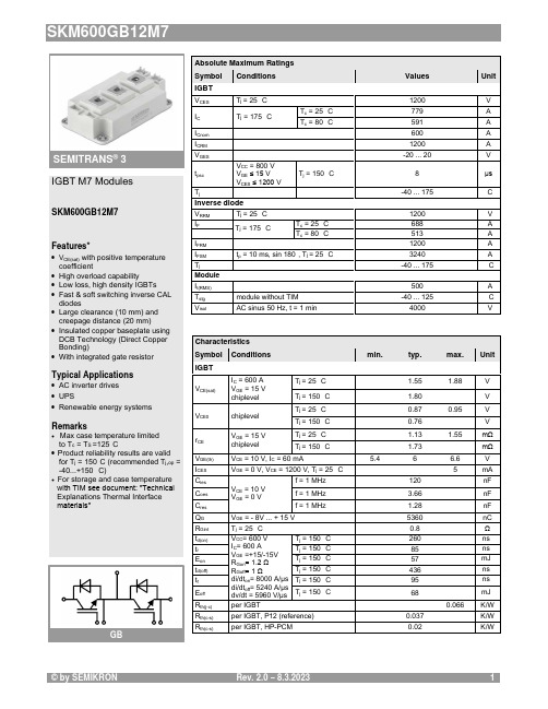
Absolute Maximum Ratings Symbol Conditions Values UnitIGBT V CES T j = 25 °C 1200 V I C T j = 175 °CT c = 25 °C 779 A T c = 80 °C591 A I Cnom 600 A I CRM1200 A V GES -20 (20)V t psc V CC = 800 V V GE ≤ 15 V V CES ≤ 1200 VT j = 150 °C8 μs T j-40 (175)°C Inverse diode V RRM T j = 25 °C 1200V I FT j = 175 °CT c = 25 °C 688A T c = 80 °C513 A I FRM 1200A I FSM t p = 10 ms, sin 180°, T j = 25 °C3240A T j-40 ... 175°C Module I t(RMS)500 A T stg module without TIM-40 ... 125 °C V isolAC sinus 50 Hz, t = 1 min4000VCharacteristics Symbol Conditions min. typ. max. UnitIGBT V CE(sat)I C = 600 A V GE = 15 V chiplevel T j = 25 °C 1.55 1.88V T j = 150 °C 1.80 V V CE0chiplevel T j = 25 °C 0.87 0.95 V T j = 150 °C 0.76 V r CE V GE = 15 V chiplevelT j = 25 °C 1.13 1.55 mΩ T j = 150 °C1.73 mΩ V GE(th)V CE = 10 V, I C = 60 mA5.46 6.6 V I CES V GE = 0 V, V CE = 1200 V, T j = 25 °C5 mA C ies V CE = 10 V V GE = 0 Vf = 1 MHz120 nF C oes f = 1 MHz 3.66 nF C res f = 1 MHz1.28 nF Q G V GE = - 8V ... + 15 V 5360 nC R Gint T j = 25 °C 0.8 Ω t d(on)V CC = 600 V I C = 600 AV GE =+15/-15V R Gon = 1.2 Ω R Goff = 1 Ωdi/dt on = 8000 A/µs di/dt off = 5240 A/µs dv/dt = 5960 V/µs T j = 150 °C 260 ns t r T j = 150 °C 85 ns E on T j = 150 °C 57 mJ t d(off)T j = 150 °C 436 ns t f T j = 150 °C 95 ns E off T j = 150 °C68mJ R th(j-c)per IGBT0.066K/W R th(c-s)per IGBT, P12 (reference)0.037 K/W R th(c-s)per IGBT, HP-PCM0.02K/WIGBT M7 ModulesSKM600GB12M7Features*∙V CE(sat) with positive temperature coefficient∙ High overload capability∙ Low loss, high density IGBTs ∙ Fast & soft switching inverse CAL diodes∙ Large clearance (10 mm) and creepage distance (20 mm)∙ Insulated copper baseplate using DCB Technology (Direct Copper Bonding)∙ With integrated gate resistorTypical Applications∙ AC inverter drives ∙ UPS∙ Renewable energy systemsRemarks∙Max case temperature limited to T c = T S =125°C∙ Product reliability results are valid for T j = 150°C (recommended T j ,op = -40...+150 °C)∙For storage and case temperature with TIM see document: ″Technical Explanations Thermal Interface materials″GBSEMITRANS ® 3Characteristics Symbol Conditions min. typ. max. UnitInverse diode V F = V EC I F = 600 A V GE = 0 V chiplevel T j = 25 °C 2.14 2.46V T j = 150 °C 2.07 V V F0chiplevel T j = 25 °C 1.30 1.50 V T j = 150 °C 0.90 V r F chiplevelT j = 25 °C 1.40 1.60 mΩ T j = 150 °C1.95 mΩ I RRM V CC = 600 V I F = 600 AV GE = -15 Vdi/dt off = 8000 A/µs T j = 150 °C 555 A Q rr T j = 150 °C92 µC E rr T j = 150 °C 43mJ R th(j-c)per diode0.09K/W R th(c-s)per diode, P12 (reference) 0.038 K/W R th(c-s)per diode, HP-PCM0.021 K/W Module L CE 15nH R CC'+EE'measured per switchT j = 25 °C 0.55mΩ T j = 150 °C0.85 mΩ R th(c-s)1calculated without thermal coupling, P12 (reference)0.0093 K/W R th(c-s)2including thermal coupling,T s underneath module, P12 (reference)0.015 K/W R th(c-s)2including thermal coupling,T s underneath module, HP-PCM 0.0078K/W M s to heat sink M635 Nm M t to terminal M52.55 Nm -Nm w325 gSEMITRANS ® 3 IGBT M7 ModulesSKM600GB12M7Features*∙V CE(sat) with positive temperature coefficient∙ High overload capability∙ Low loss, high density IGBTs ∙ Fast & soft switching inverse CAL diodes∙ Large clearance (10 mm) and creepage distance (20 mm)∙ Insulated copper baseplate using DCB Technology (Direct Copper Bonding)∙ With integrated gate resistorTypical Applications∙ AC inverter drives ∙ UPS∙ Renewable energy systemsRemarks∙Max case temperature limited to T c = T S =125°C∙ Product reliability results are valid for T j = 150°C (recommended T j ,op = -40...+150 °C)∙For storage and case temperature with TIM see document: ″Technical Explanations Thermal Interface materials″GBFig. 1: Typ. output characteristic, inclusive R CC'+ EE'Fig. 2: Rated current vs. temperature I C = f (T C )Fig. 3: Typ. turn-on /-off energy = f (I C ) Fig. 4: Typ. turn-on /-off energy = f (R G )Fig. 5: Typ. transfer characteristic Fig. 6: Typ. gate charge characteristicFig. 7: Typ. switching times vs. I C Fig. 8: Typ. switching times vs. gate resistor R GFig. 9: Transient thermal impedance Fig. 10: Typ. CAL diode forward charact., incl. R CC'+ EE'Fig. 11: CAL diode peak reverse recovery current Fig. 12: Typ. CAL diode peak reverse recovery chargePinout and DimensionsGBThis is an electrostatic discharge sensitive device (ESDS) according to international standard IEC 61340.*IMPORTANT INFORMATION AND WARNINGSThe specifications of SEMIKRON products may not be considered as any guarantee or assurance of product characteristics ("Beschaffenheitsgarantie"). The specifications of SEMIKRON products describe only the usual characteristics of SEMIKRON products to be expected in typical applications, which may still vary depending on the specific application. Therefore, products must be tested for the respective application in advance. Resulting from this, application adjustments of any kind may be necessary. Any user of SEMIKRON products is responsible for the safety of their applications embedding SEMIKRON products and must take adequate safety measures to prevent the applications from causing any physical injury, fire or other problem, also if any SEMIKRON product becomes faulty. Any user is responsible for making sure that the application design and realization are compliant with all laws, regulations, norms and standards applicable to the scope of application. Unless otherwise explicitly approved by SEMIKRON in a written document signed by authorized representatives of SEMIKRON, SEMIKRON products may not be used in any applications where a failure of the product or any consequences of the use thereof can reasonably be expected to result in personal injury. No representation or warranty is given and no liability is assumed with respect to the accuracy, completeness and/or use of any information herein, including without limitation, warranties of non-infringement of intellectual property rights of any third party. SEMIKRON does not convey any license under its or a third party’s patent rights, copyrights, trade secrets or other intellectual property rights, neither does it make any representation or warranty of non-infringement of intellectual property rights of any third party which may arise from a user’s applications. Due to technical requirements our products may contain dangerous substances. For information on the types in question please contact the nearest SEMIKRON sales office. This document supersedes and replaces all previous SEMIKRON information of comparable content and scope. SEMIKRON may update and/or revise this document at any time.。
D01超材料与多功能复合材料

D01超材料与多功能复合材料D01.超材料与多功能复合材料分会主席:周济、殷小玮、彭华新、李垚、范同祥、范润华D01-01吸波超材料的宽带化、多功能化和智能化官建国,李维,吴天龙武汉理工大学宽带薄层吸波材料对于军事隐身和众多民用领域有重要应用。
但无论是对于传统的吸波涂层材料还是新兴的超材料,其宽带性能都亟需进一步提升。
此外,复杂的应用环境还对吸波材料提出了多功能化、智能化等要求,将超材料与多样化的构成材料进行复合获得宽带化、多功能化和智能化的超材料是重要趋势。
本报告将介绍我们最近在这些方面取得的进展。
在宽带化方面,将超材料的设计与传统高性能吸波材料相结合,能够获得宽带性能远远超过单纯超材料或传统材料的全新复合吸波超材料。
在微波频段,将超材料的概念引入传统吸波材料的设计中,对吸波涂层材料进行图形化,结果显示其吸收带宽获得了大幅拓宽。
也可以将超材料与传统吸波涂层设计成多层复合结构,经过合理的设计能使得超材料的低频吸收性能与吸波涂层的高频宽带吸波性能同时得到保留甚至相互增强,这为超材料与传统吸波材料的结合提供了良好的借鉴。
类似的复合思路同样也能扩展到其它频段,如光频:将在光频段具有半介质/半金属属性的TiN用于设计宽带的光频吸收超材料,能够将介质吸收、表面等离子共振吸收和超材料的结构吸收相结合,得到宽带、可控的吸收频带,可应用于高效太阳能转换。
在多功能方面,利用超材料构成基材的高透光性质,结合有利于高透光和宽带吸收特性的非平面型超材料的设计获得了具有高可见光透过率的宽带吸波超材料。
可调超材料在某些场合可替代宽带吸波材料的作用,并且具有智能化的前景,但基于电路可调的常规调节方法其频率可调范围十分有限。
从基础材料与超材料概念结合的角度出发,利用铁氧体在外磁场作用下的宽带可调特性,结合超材料的设计,我们获得了从工频到GHz范围超宽带可调的超材料。
总之,跨越超材料与传统材料的界限,能够在宽带化、多功能化和智能化以及更多的方面具有更加光明的前景。
一种量化评估暂态电压稳定性的指标与方法_侯建兰

电力自动化设备Electric Power Automation EquipmentVol.35No.10Oct.2015第35卷第10期2015年10月0引言近年来,国内外发生的电压失稳乃至崩溃事故造成了严重的经济损失和不良的社会影响,对电力系统安全评估提出了新的挑战[1-4]。
不少电压崩溃事故源于电力系统在某个运行状态下受到大的干扰后系统电压发生较大偏移,此时由于感应电动机、高压直流(HVDC )装置等具有快速动态响应特性设备的影响导致系统失去稳定[5],属于暂态电压失稳。
目前,国内外学者对电力系统暂态电压稳定性的研究方法主要有扩展等面积法、暂态函数能量法、时域仿真法以及基于风险的评估方法等[6-13]。
文献[6]结合时域仿真提出了单机加速面积与减速面积计算方法,并根据临界机组群中单机加速面积与减速面积给出了多机系统等面积稳定判别准则。
文献[7]根据带约束动力系统稳定域理论,其受限稳定边界由边界上不稳定平衡点、周期轨和半鞍点的稳定流形以及部分可行域边界构成。
根据电力系统结构保持模型,寻找到和故障相关的一个半鞍点,然后以该点能量作临界能量,保证故障后系统满足暂态电压跌落约束。
该方法的不足之处在于半鞍点的选取不合适或者所选取能量函数本身的局限性,可能导致分析产生较大误差。
文献[8-10]考虑客观运行条件和故障等多种不确定因素的影响,将随机因素与概率分析观点引入暂态分析,提出了基于风险的暂态电压稳定性评估方法,将防止系统暂态电压崩溃而采取的控制措施所造成的控制成本作为系统失去暂态稳定性的严重度。
然而该方法包含两方面困难:一方面是预估某特定发电机或负荷停电对应的损失;另一方面在于如何识别预想故障下哪些发电机或负荷会停电以及停电的持续时间。
评估系统暂态电压稳定性的关键在于找出一种合理、实用的评价指标,文献[14]以容易引起暂态电压失稳的电动机电磁转矩-滑差曲线为基础,将故障后的极限切除时间作为系统暂态电压稳定性的衡量指标。
A_W_E2024:融合、精进与拓展的“大洗护时代”即将来临
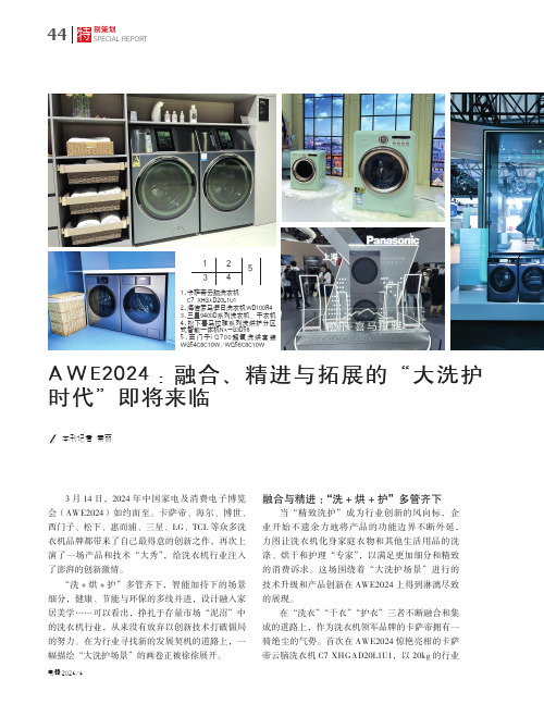
别策划44特SPECIAL REPORT2024/4融合与精进:“洗+烘+护”多管齐下当“精致洗护”成为行业创新的风向标,企业开始不遗余力地将产品的功能边界不断外延,力图让洗衣机化身家庭衣物和其他生活用品的洗涤、烘干和护理“专家”,以满足更加细分和精致的消费诉求。
这场围绕着“大洗护场景”进行的技术升级和产品创新在AWE2024上得到淋漓尽致的展现。
在“洗衣”“干衣”“护衣”三者不断融合和集成的道路上,作为洗衣机领军品牌的卡萨帝拥有一骑绝尘的气势。
首次在AWE2024惊艳亮相的卡萨帝云脑洗衣机C7 XHGAD20L1U1,以20kg 的行业A W E2024:融合、精进与拓展的“大洗护时代”即将来临本刊记者 秦丽3月14日,2024年中国家电及消费电子博览会(AWE2024)如约而至。
卡萨帝、海尔、博世、西门子、松下、惠而浦、三星、LG、TCL 等众多洗衣机品牌都带来了自己最得意的创新之作,再次上演了一场产品和技术“大秀”,给洗衣机行业注入了澎湃的创新激情。
“洗+烘+护”多管齐下,智能加持下的场景细分,健康、节能与环保的多线并进,设计融入家居美学⋯⋯可以看出,挣扎于存量市场“泥沼”中的洗衣机行业,从来没有放弃以创新技术打破僵局的努力。
在为行业寻找新的发展契机的道路上,一幅描绘“大洗护场景”的画卷正被徐徐展开。
1 23 451.卡萨帝云脑洗衣机 C7 XHGAD20L1U12.海信罗马假日洗衣机WD100R43.三星9400D系列洗衣机、干衣机4.松下喜马拉雅系列洗烘护分区式智能一体机NA-G3D585.西门子i Q 700超氧洗烘套装WG54C8C10W/WQ56C8C10W452024/4了集成各种护衣技术,选择其除湿程序,还可进行室内除湿。
惠而浦W9衣物护理机WCC303HSDT 具有超宽幅蒸汽喷射口,蒸汽均匀渗透直达纤维深处抚平衣物褶皱,辅助360°立体循环风系统,能够迅速丰盈衣物形态,实现自动熨烫塑型。
科技成果——全固态纳秒级紫外激光器
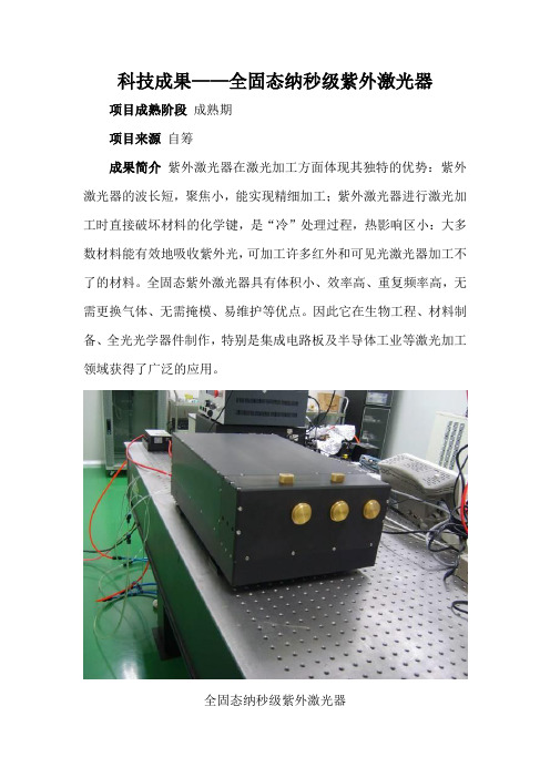
科技成果——全固态纳秒级紫外激光器项目成熟阶段成熟期项目来源自筹成果简介紫外激光器在激光加工方面体现其独特的优势:紫外激光器的波长短,聚焦小,能实现精细加工;紫外激光器进行激光加工时直接破坏材料的化学键,是“冷”处理过程,热影响区小:大多数材料能有效地吸收紫外光,可加工许多红外和可见光激光器加工不了的材料。
全固态紫外激光器具有体积小、效率高、重复频率高,无需更换气体、无需掩模、易维护等优点。
因此它在生物工程、材料制备、全光光学器件制作,特别是集成电路板及半导体工业等激光加工领域获得了广泛的应用。
全固态纳秒级紫外激光器目前紫外激光器的发展非常迅速,瓦级功率以上高重频全固态激光器不断应用于加工,国内外研究机构和公司不断向更高功率(数十瓦级)、更高重频(几十甚至几百kHz)方向发展。
目前我们已经研制成功了5W、50kHz的紫外355nm激光器,脉宽25ns。
已经做成样机,性能稳定,用于LED蓝宝石晶圆裂片划线,划线深度达到200μm,线宽小于10μm,划痕光滑均匀,几乎无热影响区。
技术特点通过高效率端面泵浦结构方式得到基模红外1064nm激光,再经过多级放大结构,得到高功率的红外高光束质量基频光,再通过高效率变频技术,最后得到5W、50kHz、25ns脉冲紫外355nm激光。
光束质量因子M2<1.3,功率长期稳定性<±2%。
内部光学结构采用紫外胶光固化粘接,结构小巧牢靠,对环境适应程度高。
通过紫外显微物镜的聚焦,聚焦光斑直径在μm级别,加工尺寸小于10μm。
通过紫外激光器的开发,相应的也取得了更高功率的红外和绿光高光束质量激光技术。
专利情况目前国内外并无相关的专利限制,主要是在工艺实现难度比较高。
目前我们已取得专利8项。
市场分析紫外355nm激光器目前国际市场价格约为2万美元/W,中大功率全固态紫外激光器市场均被国外厂商占据。
据行业协会统计,2010年我国全固态紫外激光器市场销售额达到5亿元人民币,比2009年增长了25%。
不同等级数据中心供电系统和配电系统的配置架构
运营维护技术Telecom Power Technology 2023年10月25日第40卷第20期231电系统的设计与配置。
在这个方面,Tier IV 和Tier III 数据中心具有较高的维护性,因为它们的供电系统和配电系统都设计为可以在不影响服务的情况下进行设备维护与升级。
而在Tier II 和Tier I 数据中心,由于其供电系统只有单一路径,因此在进行设备维护或升级时,可能需要暂时停机。
3.4 能效对比数据中心的能效主要取决于其供电系统和配电系统的设计与配置。
在这个方面,Tier IV 和Tier III 数据中心的能效通常优于Tier II 和Tier I 数据中心。
这是因为高等级数据中心的供电系统和配电系统通常使用更先进的技术与设备,如高效的不间断电源和电源分配单元,以及精确的电力管理系统,可以减少电力损耗和提高能源利用率。
然而,高等级数据中心的运行和维护成本也更高。
4 数据中心供电系统和配电系统的未来发展趋势4.1 高效能源使用随着能源成本的上升和环保要求的加强,数据中心的能效将成为其设计和运行的重要指标。
未来的数据中心可能会更多地使用高效的电源设备,如高效的不间断电源和电源分配单元,以及精确的电力管理系统,来减少电力损耗和提高能源利用率。
4.2 绿色能源应用随着可再生能源技术的发展,未来的数据中心可能会更多地使用风能、太阳能等绿色能源,以减少对化石能源的依赖和减轻环境压力。
同时,数据中心可能也会利用先进的能源存储技术,如锂离子电池和飞轮,来储存和调度可再生能源。
4.3 智能化管理随着人工智能和物联网技术的进步,未来的数据中心可能会实现更智能化的供电系统和配电系统管理。
这可能包括基于机器学习的故障预测和诊断、基于大数据的电力使用优化以及基于物联网的设备远程监控和控制。
4.4 模块化和标准化设计为了提高数据中心的建设效率和运行灵活性,未来的数据中心可能会采用更多的模块化和标准化设计,这可能包括标准化的电源和配电设备、模块化的电力系统架构以及插拔式的设备接口。
高压直流输电工程共用接地极运行风险及防范措施工程应用

Telecom Power Technology电力技术应用 2023年10月25日第40卷第20期83 Telecom Power TechnologyOct. 25, 2023, Vol.40 No.20熊 伟,等:高压直流输电工程共用 接地极运行风险及防范措施工程应用用接地极的情况很难实现。
2 高压直流输电工程共用接地极运行风险分析2.1 共用接地极对系统运行方式的影响在高压直流输电工程中,共用接地极的运行方式直接关系着整个系统的稳定性、可靠性和安全性。
正常情况下,高压直流输电系统通过共用接地极实现电流的均衡分布,以保持系统的双极运行状态。
然而,共用接地极导致正负极逆变器和直流换流变的工作状态不一致,进而影响系统的电气稳定性。
在某些情况下,系统需要采用单极大地回线方式运行,共用接地极的存在会干扰这种运行模式的实施。
共用接地极的电势变化影响系统中单极运行模式下的电压分布,从而使得系统难以稳定地维持单极运行状态,导致系统的直流功率调节困难,影响系统的运行灵活性和可靠性。
2.2 共用接地极对系统运行性能的影响共用接地极上电流的变化会引起接地极电压波动、过热以及电阻增大等问题。
电流的变化会导致接地极电压的波动,进而影响系统的电气稳定性。
过高的电流使得接地极过热,导致接地极材料受损,从而降低其可靠性。
同时,共用接地极的运行方式会对系统的控制和保护功能造成潜在风险。
特别是在有电流流过的共用接地极中,当一个系统发生故障时,其他系统也会受到影响,导致整个系统运行不稳定。
例如,如果A 系统发生直流断路器故障,共用接地极上的电流变化导致B 系统的直流电压波动,影响B 系统的功率控制。
这种相互影响导致控制系统出现误判,增加系统发生故障的风险,甚至引发事故。
共用接地极对系统的经济性和效率也会产生影响,电流在共用接地极上的流动会引起能量损耗,从而降低系统的传输效率,能量损耗不仅浪费电能,还增加系统的运行成本。
2.3 共用接地极对环境和设备的影响共用接地极的运行会对相关设备造成影响。
D打印试题

3D打印技术相关试题一、填空题1.成都增材制造 -3D 打印工程技术研究中心落户〔 5719工厂〕。
2.世界3D打印技术产业大会第二届会议2021年在〔青岛〕召开。
3.目前中国唯一的 3D 航空动力小镇在〔彭州丽春〕。
4.中国 3D 航空动力小镇将依赖〔 5719工厂〕的新兴优势产业,实现军民交融睁开。
5.3D 打印技术被英国〔?经济学?〕杂志称为“将带来第三次工业革命〞的数字化制造技术。
6.中国 3D 打印研究院于 2021年 8 月 7 日在〔南京〕成立。
7.3D 打印设备目前主要的热源有〔激光束〕、〔电子束〕、〔等离子束〕。
8.中国工程院院士〔刘大响〕于 2021年 2 月莅临中国 3D 航空动力小镇。
9.激光 3D 打印设备目前常用的激光器是光纤激光器,光纤激光器的波长一般是〔 1070纳米〕。
10.2021年 3 月 24 日,中国 3D 打印技术产业创新中心于在〔南京〕成立。
11.航空发动机被誉为飞机的〔心脏〕。
12.LENS 技术是指〔激光净近成形〕技术。
13.我国目前唯一专注于 3D 打印制造的中国工程院的院士是〔卢秉恒〕。
14.EBSM 技术是指〔电子束选区消融〕技术。
15.中国 3D 打印技术产业缔盟于 2021年在〔北京〕成立。
16.EBF 技术是指〔电子束熔丝聚积〕技术。
17.航空发动机主体结构包括〔压气机〕、燃烧室、涡轮和尾喷口。
18.PBF 技术是指〔等离子束熔丝聚积〕技术。
19.?我心遨游?一书是航空动力专家中国工程院院士〔刘大响〕的回忆录。
20.3D 打印技术用于再制造时称为〔 3D 打印再制造〕技术。
21.北航王华明教授因采用 3D 打印技术打印〔钛合金〕资料而获取国家创立一等奖。
22.国内最早的一部关于介绍 3D 打印技术的书是〔黄卫东〕编写的。
23.〔颜永年〕被称为中国 3D 打印第一人。
24.成都市在〔 2021〕年成立了成都市 3D 打印产业技术创新缔盟。
智能仿生生态大发展, 柔性电子皮肤成多场景应用宠儿
智能仿生生态大发展,柔性电子皮肤成多场景应用宠儿作者:徐迅捷来源:《海外星云》2021年第01期两年前,擅长制造噱头的“机器人索菲娅”被授予沙特公民身份,机器人能否以公民身份进入人类的生活一时成为热点话题。
而近日热播国产电视剧《你好,安怡》中芯机人融入家庭的场景将这类议题再次引爆。
如今人工智能的发展和工业水平的提升,让我们觉得机器人融入人类的日常生活不再遥远,仿生技术也随着这类题材热度提升越来越受公众关注。
络绎学术 Online 直播第二期,我们邀请了香港城市大学生物医学工程系助理教授、博导于欣格为大家分享:现实版“头号玩家”,电子皮肤触觉感知和未来 VR 技术。
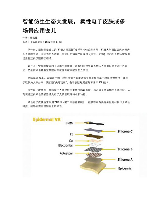
柔性电子皮肤是一种新型仿人类皮肤的柔性传感器系统。
通过电子装置仿生人类皮肤,从而使得这类柔性传感系统具有了人类皮肤的特点和功能。
柔性电子皮肤通常采用PDMS(聚二甲基硅氧烷)、硅胶等本身具有柔性的材料作为柔性衬底,能够实现宏观结构上的柔性。
2019 年,于欣格团队关于电子皮肤的研究发表在《自然》杂志上。
3 毫米柔性电子皮肤的研究进展有条不紊地进行了下去。
在分享中,于欣格用电影《头号玩家》的例子生动地展现了这一研究的体验感。
萨曼莎用手滑过韦德肩膀时,玩家感觉到的真实触感就需要器件提供反馈。
要想清晰获取手滑动皮肤的感觉,技术上就对器件的密度要求更高。
目前,他们的团队将单个反馈单元做到毫米量级,几乎达到了人体皮下触觉反馈器的分布极限,也就是达到了人体分辨的极限,因而反馈的触感也更真实自然。
这 3 毫米的柔性电子皮肤内有一个致动器(actuators),这是互相连结的“按钮”。
每个致動器都接通射频天线,以无线方式传递信息和供电。
致动器发出的振动频率以毫米计,且只需1.75 毫瓦的功率便能诱发触感,仅需市面现有致动器所需功率的 2%。
配套的软件一旦收到指令,就会迅速将讯息传递到致动器,使用者就可以感到触感。
在外在形态上,目前用在皮肤 VR 上的 NFC 通信工作距离可以延展到近 1 米。
- 1、下载文档前请自行甄别文档内容的完整性,平台不提供额外的编辑、内容补充、找答案等附加服务。
- 2、"仅部分预览"的文档,不可在线预览部分如存在完整性等问题,可反馈申请退款(可完整预览的文档不适用该条件!)。
- 3、如文档侵犯您的权益,请联系客服反馈,我们会尽快为您处理(人工客服工作时间:9:00-18:30)。
Spotlight Figure 1: Economics of HVDCSource: Alstom Gridgate-commutated thyristors (IGCTs) are being used in VSCs,IGBT is the most promising as it requires little power for itscontrol. IGBTs also use relatively high frequency switchingand pulse width modulation (PWM) technology for voltageand current regulation, thus making them smaller and lighterin size. This is turn makes the IGBT-based power device muchsmaller in size, lighter in weight, more energy efficient andmore cost effective than the traditional LCC-based controlcircuits. Previously, VSC technology was only used forunderground/submarine cables, but now it is being deployedin both overhead and underground projects.The HVDC VSC transmission system is offered underdifferent names by the three leading manufacturers. ABB hasnamed this concept HVDC Light, Siemens calls it HVDC PLUS(Power Link Universal System) and Alstom Grid markets thisconcept as HVDC MaxSine.VSC-LCC hybrid: This emerging concept entails developing amulti-terminal HVDC system (MTDC) by combining VSC andLCC technologies to help eliminate the disadvantages of boththe HVDC technologies. Such an arrangement is presentlybeen explored by both engineers and power utilities. It isexpected to gain significant importance in the coming years,especially to connect offshore wind facilities. However, such asystem will require complex control schemes to ensure itfunctions efficiently under different operating conditions.As per Alstom Grid estimates, the installed HVDC capacityhas grown five-fold from 3 GW per year to 15 GW per year.Ultra HVDC (>600 kV) and VSC is expected to drive the futureexpansion of the industry. Alstom Grid also estimates that theHVDC market (convertor business) is expected to grow toEUR60 billion by 2020.Technical AdvantagesAC systems have certain inherent challenges such asexistence of relative elements (inductance and capacitance)in lines, which limits their transmission capacity; additionalcomponents such as series capacitors or shunt reactors needto be installed in an AC network to address issues related tocompensation; connecting several AC systems may lead tosystem instability. HVDC transmission offers manyadvantages over traditional AC transmission:•HVDC eliminates reactive capacitance associated with longAC underground/submarine cables;•power transfers and voltage in a DC system can becontrolled and modulated;•DC transmission has no fault currents and acts as a fault‘firewall’, thus preventing faults in the AC systemembedded with HVDC interconnections;•DC systems have a smaller footprint as they require lessright-of-way (RoW), less land and cause less disturbance;•DC reduces electromagnetic fields from transmission linesto insignificant levels;•DC has the ability to link asynchronous power systems(different voltages and frequencies);•DC system installtion involves lower capital costs (aftercentain distance) and results in lower losses as comparedto an AC system; and•DC technology based on VSC can help black start AC powergrids after grid failure or blackout.HVDC SchemesHVDC has a ‘more power per tower’ advantage as it requiresless space and infrastructure to transmit power as comparedto traditional HVAC technology. The same amount of electricitythat can be transferred by five 500 kV AC towers can betransferred by only two ±500 kV DC towers or just one ±800 kVDC tower. While HVDC is uneconomical for transferring powerover short distances as DC convertor stations requiresubstantial investment as compared to AC stations, at distancesover 700 km for overhead lines and over 50 km for submarinecables, the HVDC becomes a more economical option.Broadly, HVDC can be classified into three types ofschemes: back-to-back (BTB), point-to-point connections andoffshore HVDC grid connections. LCC HVDC technology canbe deployed for developing both point-to-point and BTB HVDCsystems while VSC HVDC technology is ideal for connectingoffshore wind farms as well as black starting the grid.A BTB HVDC interconnection is when two convertorstations are built under the same roof. Here, one convertorstation converts AC power (e.g. 380 kV, 60 Hz) to DC and thenthe second convertor station re-converts the DC to the desiredAC voltage and frequency (e.g. 400 kV, 50 Hz), which can betransmitted further to the connected grid. Here the length ofHVDC line or cable is zero.Global Transmission Report|October 201239。