蛇牌gn300
日本威达镜头介绍

28/1.9:有浮动镜片设计,前组转动(!)不伸缩。
90/2.5:现代摄影杂志有两只分辨率最高的镜头,一只是LEICA苏米克隆DUAL RANGE标头,另一只就是他。1:2微距头,特配接圈含三片镜片纠正近场相差后1:1。David Ruether所评镜头中Nikon卡口最好的微距头。Tokina产,后Tokina重新设计此头为90/2.5 1:1,PHOTODO上得分和LEICA苏米克隆依然持平,和现代摄影结果相同。
罗润富整理
下表为威达镜头转包合同制造商与镜头序号对应数字一览表
6 奥林巴斯
9 柯西那
13 施耐德光学
22 Kino
25 Ozone光学
28 Komine
32 玛珂那
33 Asanuma
37 图丽
42 Bauer
44 Perkin Elmer(美国公司)
Vivitar对后来影响最大的是70-210/3.5,子孙满堂。最值得收入的当是90/2.5、90-180/4.5、450/4.5。除了Nikon外,它是唯一在长中短变焦都拥有微距的厂家。也许它们之间有什么关系。但是Vivitar和Nikon以及做出大光圈的Olympus应当是Zoomar之后把微距现代化的三大功臣。
德国蛇牌氩气刀
设备名称高频电刀药(械)准字 4654656德国蛇牌gn300电刀gn300是函盖多种术式适合全科室使用的多功能电外科工作站蛇牌特有专利功能双极电切允许在安全的双极模式下进行敏感组织的切割、分离比例输出依据脚踏开关灵活调节功率的输出,简化操作,缩短手术时间德国蛇牌gn300电刀记忆功能同时记忆4组工作状态氩气刀插座可结合gn370控制器升级成为氩气工作站德国蛇牌gn300电刀输出特性双刀笔输出双极电切,单极电切双极内窥电切功能输出功率0~80w 阻抗700~1300欧姆具有两种电凝效果柔和电凝、强力电凝双极电凝功能输出功率0~80w(10w以内0.1步长调节)阻抗70~250欧姆自动电切具有自动电压控制的单极切割高能电切具有自动电弧控制的单极切割、具有汽化电切软件功能功率峰值系统根据需要释放动态的、以毫秒计算的附加电脉冲,使功率达到需要值高频功率限值的设置使用向上/向下(up/down)增量键的hf功率极限调整电切效果选择可用按键选择4种电切效果及电凝效果单极内窥混切输出功率0~100w 阻抗250~600欧姆单极电凝输出功率0~80w 阻抗700~1300欧姆单极喷凝输出功率0~80w 阻抗70~250欧姆电源电压: 220v电源频率: 50-60hz 保护等级: 1类型: cf 低频漏电:符合iec601-1标准高频漏电:符合iec602-2标准输出频率: 447khz德国蛇牌gn300电刀本公司成立于2009年,位于上海市宝山区沪太路1580号,主要销售代理医疗仪器和医疗设备,从成立以来公司一直以"携手合作,共创未来"为企业宗旨,用我们的热诚,真心为您服务!公司主要销售代理进口医疗设备,如德国蛇牌电凝器电刀,日本铃谦心电图机,美国鸟牌呼吸机,丹麦国际听力设备,以及各类手术室设备和检验科设备.希望广大业内人士电话洽谈业务.德国蛇牌gn300电刀搜了网-德国蛇牌GN300电刀,手术专用设备,德国蛇牌电刀,GN300,这里云集了众多的供应商,采购商,制造商。
可攜式投影機 V300X V260X V230X V260 V230 使用手冊说明书

型號
V300X/V260X/V230X/V260/V230
使用手冊
2011 年 1 月第一版
DLP 和 BrilliantColor 是 Texas Instruments (德州儀器有限公司)的商標。 IBM 爲 International Business Machines Corporation (國際商業機器公司)的商標或註冊商標。 Macintosh, Mac OS X 和 PowerBook 爲 Apple Inc. (蘋果公司)在美國和其他國家註冊的商標。 Microsoft、Windows、Windows Vista、Internet Explorer、 .NET Framework 和 PowerPoint 爲 Microsoft Corporation (微軟公司)在美國和/或其他國家的註冊商標或商標。 MicroSaver 爲 ACCO 品牌的一個分公司 Kensington Computer Products Group 的註冊商標。 Virtual Remote Tool (虛擬遙控工具)使用 WinI2C/DDC library, © Nicomsoft Ltd。 HDMI、HDMI 標誌和 High-Definition Multimedia Interface 爲 HDMI Licensing LLC.的商標或註冊商標。
切勿讓紙夾和紙屑等異物掉入投影機內。切勿試圖找回可能掉入投影機內的任何物品。切勿將鐵絲或者螺絲起子 等金屬物體插入投影機內。若發現有物體掉入投影機內部,須立即斷開電源,然後委託有維修資格的維修服務人 員取出物體。 切勿在投影機上面放置任何物體。 雷雨天不要觸摸電源插頭。此舉可能引起電擊或者火災。 投影機規定操作電源爲 200-240 伏特 50/60 赫茲交流電。在使用投影機之前,須確認所用電源是否符合本投影機 要求。 切勿在投影機啓動狀態下窺視鏡頭。此舉會導致眼睛嚴重受傷。
Matrix_210和300VisiSet设置
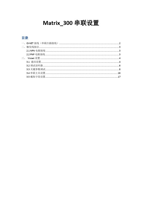
Matrix_300串联设置目录一、ID-NET接线(串联扫描接线) (2)二、触发线接法 (3)2.1 NPN电眼接线 (3)2.2 PNP电眼接线 (3)三、Visiset设置 (4)3.1 通讯设置 (4)3.2调试读码器 (6)3.3关键参数调试 (8)3.4串联主从设置 (16)3.5截取字段设置 (17)一、ID-NET接线(串联扫描接线)将俩接线盒上的接点ID-、ID+、REF、Shield一一对接;vdc接24V,GND接0V,Earth接地。
同一CBX-100上的2组ID-NET是相通的,接哪组都可以。
二、触发线接法2.1 NPN电眼接线+V和I1A(18)接电源正级24V,I1B(19)接触发信号线,-V接电源负级0V。
2.2 PNP电眼接线+V接电源正级24V,I1A接触发信号线,I1B和-V接电源负级0V。
三、Visiset设置3.1 通讯设置打开VisiSet后,程序窗口如下图所示:点击工具栏中的Options按钮,会出现下面的窗口:此窗口用来设置读码器与电脑通讯所用的串口的设置。
例如,选择使用哪一个串口,波特率是多少,是否有奇偶校验等。
把这些设置与电脑串口的设置改为一样。
然后点击Save 关闭此窗口。
出厂时的设定为:115200-8-N-1 (串口连接)如下图,点击Connect:大约2秒钟,VisiSet与读码器连接成功,连上后的状态如下图:测试工具数据显示窗口左边的一列按钮为调试工具,用于调试读码器;右边为数据显示窗口,可以显示读到的条码的内容。
以太网连接:若采用以太网连接方式,需要将连接读码器的电脑设置静态IP,且IP和读码器IP地址需要在同一个网段内。
例如:读码器出厂IP为:172.24.24.1, 子网掩码:255.255.255.0,那么电脑IP需要设定为:172.24.24.X,子网掩码:255.255.255.0注:X可设置为2—255之间的任何值!3.2调试读码器VisiSet与读码器成功连接后,我们就可以对读码器进行调试。
蔡司镜头大全(蔡司主义)

蔡司镜头大全bullcai2006.6.2蔡司,这个创造了无数传说的光学巨人,在制作了一大批具有极高水准的高端产品的同时,对其低端产品仍然保持一丝不苟的态度。
有蔡司以后,享受超高成像质量不再是富人俱乐部的专利。
一支P50/1.7足以让你一窥摄影的精彩世界,仅仅千余元的P45/2足以和价格几倍于它的镜头抗衡!作为一个以盈利为目的生产厂商,一分钱一份货本无可厚非,但是蔡司做到了一分钱三分货。
一下是本人对蔡司的不负责任的狂想,取名蔡司主义。
喜欢的色友不妨进来多看两眼,不喜的朋友尽可以嗤之以鼻,嘟囔一句烧糊了的发烧友Y/C口单反镜头Distagon T* 25mm F2.8Distagon 取名于Distance(距离),和Gonio(角度)。
由于SLR的特有的反光镜结构,所以不得不增加法兰距离,由Erhard Glatzel博士(同时也是Hologon的设计者)设计。
在Distagon的家族里有D16,D15,D18,D21, D25, D28和D35等。
这支Distagon 25/2.8 被称为“素人好きなレンJn7;”,行家里手的最爱!那谁谁,大师寇德卡不就是就是用D25吗!D25/2.8,早在Contarex时代就存在的老设计,80度的视角,仅仅比26mm稍微大一点点。
奇了怪了,视角和D28mmF2.8相近,光圈也一般大,相比之下D28mm还要锐利一些,可偏偏就要贵出近一倍的价钱?如果评论一张作品仅仅限于锐度的话,那么就说明你还处于初级阶段:P一幅油画,凑到跟前看,仅仅是一笔一笔的油彩而已,后退几步以后它才是艺术。
D25在光圈圈开时画面中央超过220pl/m的解像度,由中心至周边解像度渐次下降。
利用这个特性可以创造出它特有的立体感,适合人文题材的拍摄。
实际上蔡司的D18,D25,D28都存在[像场面弯曲]的情况,但是在蔡司的神来之笔下,却创造出它独特的魅力,不得不佩服这位光学巨人才华!D25的光圈收到F8的时候,周边的解像度和反差大幅度改善,又是拍风景的好头。
各类液晶屏查询

M190A1-L02 M190EN02 M190EN03 M190EN04 M190PW01 M201EW02 M201UN02 M220Z1-L01 T13...(D0191203) T1702 T200XW01 T260XW02 UB133X01 UB133X03 UB141X01 UB141X02 UB141X03 UM170E01 EM170S0 M150X3-L01 M150X4-L06 M150X4-L06-X M150X4-L08 M150X4-L08-X M170E2-02 M170E4 M170E6 N141X201 N141X5-L04 N141X6-L01 N150P3 X CARD N154C1-L02 N154X3 V201B1-L01 V230W1-L02 V320B1-L 141XF02S CLAA141XA12 CLAA141XB01 CLAA141XC01 CLAA141XF01 CLAA150PA01 CLAA150PB01 CLAA150PB03 CLAA150XG09 CLAA150XH01 CLAA150XH01A
LVDS LVDS LVDS LVDS LVDS LVDS LVDS LVDS LVDS LVDS LVDS LVDS LVDS LVDS LVDS LVDS LVDS LVDS LVDS LVDS LVDS LVDS LVDS LVDS LVDS LVDS LVDS LVDS LVDS LVDS LVDS LVDS LVDS LVDS LVDS LVDS LVDS LVDS LVDS LVDS LVDS LVDS LVDS LVDS LVDS LVDS LVDS
屏的品牌
AU AU AU AU AU AU AU AU AU AU AU AU AU AU AU AU AU AU AU AU AU AU AU AU AU AU AU AU AU AU AU AU AU AU AU AU AU AU AU AU AU AU AU AU
RICOH Caplio R1 说明书

本使用說明書記載使用本産品進行攝影和重播的方法和使用上的注意事項。
使用前,請閱讀完本說明書,以便您能充分地靈活運用本産品的功能。
閱讀後請妥善保管,以便在您需要的時候,能夠立即查閱。
理光股份公司•嚴禁擅自轉載本書的部分或全部內容。
© 2004 RICOH CO.,LTD. All rights reserved.•關於本書內容,將來若有變更,恕不另行通知。
•本書內容的作成過程中力求圓滿,萬一發現不明點及錯誤、記載遺漏等,請按照巻末的通訊方式和我們聯繫。
Microsoft ,MS ,Windows ,DirectX 是美國Microsoft Corporation 在美國及其他國家登錄的注冊商標。
Macintosh 是在美國及其他國家已登錄的美國Apple Computer.Inc.的商標。
Adobe 和Adobe Acrobat 是Adobe Systems Incorporated 的商標。
公司名稱及産品名稱是各公司的商標或注冊商標公司名稱及産品名稱是各公司的商標或注冊商標。
關於安全警示爲確保安全使用相機,請務必在使用前詳細閱讀安全警示。
關於攝影測試請務必預先進行攝影測試,確認相機能夠正常地進行記錄。
關於著作權以著作權爲目的的書籍、雜誌、音樂等作品,限定在個人或家庭內以及基於此類目的的範圍內使用。
除此之外,禁止擅自進行複製和改動。
關於使用萬一因本産品的問題導致無法記錄和重播時,不負責記錄內容的補償,敬請諒解。
關於保修證在海外使用時,萬一出現故障、問題時,關於在當地的售後服務及相關費用不負責任,敬請諒解。
關於電波故障和其他電子設備進行連接設置時,可能會出現相互産生不良影響的情況。
特別是近處有電視機或收音機時會出現雜音。
此時,敬請進行如下處置:•盡可能的遠離電視機或收音機•改變電視機或收音機等的天綫方向•使用其他的插座1裝載4.8倍高倍率廣角變焦鏡頭厚25mm 的薄型小型機身,裝載能夠彌補通常攝影距離28~135mm*、4.8倍的高倍率的廣角鏡頭。
H3BA-N
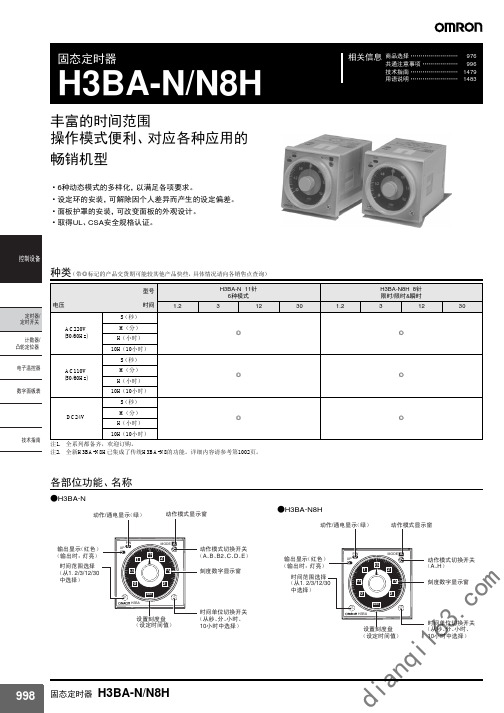
1.0KV(电源端子间) 2.0KV(导电部端子和露出非导电金属部间), 但24VDC 1.5KV
AC型式 :±1.5KV(电源端子间),±600V(输入端子间); DC型式 :±480V(电源端子间),±600V(输入端子间) 模拟器形成分波噪声(宽幅 :100ns/1μs,开始1-ns)
*IEC061000-4-5
H3BA-N(接点输出)
H3BA-N8H(A模式)
V V
V V
䍋
ᷙ
ԡ
ࡼ
ᵕ
䕧
䕧
䕧
ܹ
ܹ
ܹ
567
4
8
3
9
2
10
1 11
˄ˉ˅˄̚˅
⬉⑤
˄ˇ˄˅̚˅
H3BA-N8H(H模式)
˄ˉ˅ ˄̚˅
45
3
6
2 1
7
8
˄ˇ˅ ˄̚˅
˄ˉ˅˄̚˅
⬉⑤
˄ˇ˅˄̚˅
4 3
˄ü˅ ˄̚˅
2 1
5 6
7 8
˄ˇ˅ ˄̚˅
⬉⑤
˄ü˅˄̚˅
5 6 7
ࡼ/ ԡㄝ
2 䕧ܹ⫼OV
ԧㅵONᯊࡼ
⚍ONᯊࡼ
5 6 7
ࡼ/ ԡㄝ
2 䕧ܹ⫼OV
ԧㅵONᯊࡼ
ˇ Ⳉ⌕ ˉ ⬉⑤
ᅮᯊ఼
5 6 7
ࡼ/ ԡㄝ
2 䕧ܹ⫼OV
●无电压输入
无接点输入
1.「短路等级」 晶体管ON残留电压1V以下, ON时阻抗1KΩ以下
2.「开放等级」 晶体管OFF OFF时阻抗200KΩ以下
ᯊ䯈ऩԡߛᤶᓔ݇ ˄Ң金ǃߚǃᇣᯊǃ 10ᇣᯊЁ䗝ᢽ˅
SWF型风机参数

16.5
S3
460
11
1100
53521
ES65S
E3S30
800
980
1100
1450
22
94
544
12
1200
6B35B
6515B
62Q5B
800
11D0
960
22
S5
635
13
1300
84SB6
80SB6
76260
880
990
1120
960
30
&5
736
型号
0
D1
□2
HI
M?
M看
■ 4
1166
122Q
TOD
770
73Q
7K
&3。
6-5Q
14*14
4-4118
15
1212
1275
1330
750
跄。
E70
SSG
S7C
7-00
16-力14
4-3 IS
13
1313
1372
1443
&0G
B70
520
9»0
93C
7S0
16-CC14
4-E1E
型号
气流进部□直役
翼・
<H Vh3
全压cPG
转速
(r/n i n)
960
2SS0
7.5
65
156
7
7M
313BC
之耿力
600
R忖
QS0
14M
11
上如
600
3735C
W25Q128JVSIQ规格书_W25Q128JVSIQ中文资料_W25Q128JVSIQ Datasheet

Publication Release Date: May 02, 2017Revision D3V 128M-BITSERIAL FLASH MEMORY WITH DUAL/QUAD SPI- 1 -Table of Contents1. GENERAL DESCRIPTIONS ............................................................................................................. 42. FEATURES ....................................................................................................................................... 43.PACKAGE TYPES AND PIN CONFIGURATIONS ........................................................................... 5 3.1 Pin Configuration SOIC 208-mil ........................................................................................... 5 3.2 Pad Configuration WSON 6x5-mm/ 8x6-mm ....................................................................... 5 3.3 Pin Description SOIC 208-mil, WSON 6x5-mm / 8x6-mm ................................................... 5 3.4 Pin Configuration SOIC 300-mil ........................................................................................... 6 3.5 Pin Description SOIC 300-mil ............................................................................................... 6 3.6 Ball Configuration TFBGA 8x6-mm (5x5 or 6x4 Ball Array) ................................................. 7 3.7Ball Description TFBGA 8x6-mm ......................................................................................... 7 4. PIN DESCRIPTIONS ........................................................................................................................ 8 4.1 Chip Select (/CS) .................................................................................................................. 8 4.2 Serial Data Input, Output and IOs (DI, DO and IO0, IO1, IO2, IO3) ..................................... 8 4.3 Write Protect (/WP) .............................................................................................................. 8 4.4 HOLD (/HOLD) ..................................................................................................................... 8 4.5 Serial Clock (CLK) ................................................................................................................ 8 4.6Reset (/RESET) (8)5. BLOCK DIAGRAM ............................................................................................................................ 96.FUNCTIONAL DESCRIPTIONS ..................................................................................................... 10 6.1 Standard SPI Instructions ................................................................................................... 10 6.2 Dual SPI Instructions .......................................................................................................... 10 6.3 Quad SPI Instructions ......................................................................................................... 10 6.4 Software Reset & Hardware /RESET pin ........................................................................... 10 6.5Write Protection (11)6.5.1 Write Protect Features (11)7. STATUS AND CONFIGURATION REGISTERS ............................................................................ 12 7.1Status Registers (12)7.1.1 Erase/Write In Progress (BUSY) – Status Only ................................................................ 12 7.1.2 Write Enable Latch (WEL) – Status Only .......................................................................... 12 7.1.3 Block Protect Bits (BP2, BP1, BP0) – Volatile/Non-Volatile Writable ................................ 12 7.1.4 Top/Bottom Block Protect (TB) – Volatile/Non-Volatile Writable ....................................... 13 7.1.5 Sector/Block Protect Bit (SEC) – Volatile/Non-Volatile Writable ....................................... 13 7.1.6 Complement Protect (CMP) – Volatile/Non-Volatile Writable ............................................ 13 7.1.1 Status Register Protect (SRP, SRL) – Volatile/Non-Volatile Writable ............................... 14 7.1.2 Erase/Program Suspend Status (SUS) – Status Only . (15)Publication Release Date: May 02, 2017- 2 - Revision D7.1.3 Security Register Lock Bits (LB3, LB2, LB1) – Volatile/Non-Volatile OTP Writable .......... 15 7.1.4 Quad Enable (QE) – Volatile/Non-Volatile Writable .......................................................... 15 7.1.5 Write Protect Selection (WPS) – Volatile/Non-Volatile Writable ....................................... 16 7.1.6 Output Driver Strength (DRV1, DRV0) – Volatile/Non-Volatile Writable ........................... 16 7.1.7 Reserved Bits – Non Functional ........................................................................................ 16 7.1.8 W25Q128JV Status Register Memory Protection (WPS = 0, CMP = 0) ............................... 17 7.1.9 W25Q128JV Status Register Memory Protection (WPS = 0, CMP = 1) ............................... 18 7.1.10 W25Q128JV Individual Block Memory Protection (WPS=1) . (19)8. INSTRUCTIONS ............................................................................................................................. 20 8.1Device ID and Instruction Set Tables (20)8.1.1 Manufacturer and Device Identification ................................................................................ 20 8.1.2 Instruction Set Table 1 (Standard SPI Instructions)(1)........................................................... 21 8.1.3 Instruction Set Table 2 (Dual/Quad SPI Instructions) ........................................................... 22 Notes: (22)8.2 Instruction Descriptions (23)8.2.1 Write Enable (06h) ............................................................................................................... 23 8.2.2 Write Enable for Volatile Status Register (50h) .................................................................... 23 8.2.3 Write Disable (04h) ............................................................................................................... 24 8.2.4 Read Status Register-1 (05h), Status Register-2 (35h) & Status Register-3 (15h) .............. 24 8.2.5 Write Status Register-1 (01h), Status Register-2 (31h) & Status Register-3 (11h) .............. 25 8.2.6 Read Data (03h) ................................................................................................................... 27 8.2.7 Fast Read (0Bh) ................................................................................................................... 28 8.2.8 Fast Read Dual Output (3Bh) ............................................................................................... 29 8.2.9 Fast Read Quad Output (6Bh) .............................................................................................. 30 8.2.10 Fast Read Dual I/O (BBh) ................................................................................................... 31 8.2.11 Fast Read Quad I/O (EBh) ................................................................................................. 32 8.2.12 Set Burst with Wrap (77h) .................................................................................................. 34 8.2.13 Page Program (02h) ........................................................................................................... 35 8.2.14 Quad Input Page Program (32h) ........................................................................................ 36 8.2.15 Sector Erase (20h) ............................................................................................................. 37 8.2.16 32KB Block Erase (52h) ..................................................................................................... 38 8.2.17 64KB Block Erase (D8h) ..................................................................................................... 39 8.2.18 Chip Erase (C7h / 60h) ....................................................................................................... 40 8.2.19 Erase / Program Suspend (75h) ......................................................................................... 41 8.2.20 Erase / Program Resume (7Ah) ......................................................................................... 42 8.2.21 Power-down (B9h) .............................................................................................................. 43 8.2.22 Release Power-down / Device ID (ABh) ............................................................................. 44 8.2.23 Read Manufacturer / Device ID (90h) ................................................................................. 45 8.2.24 Read Manufacturer / Device ID Dual I/O (92h) ................................................................... 46 8.2.25 Read Manufacturer / Device ID Quad I/O (94h) ................................................................. 47 8.2.26 Read Unique ID Number (4Bh). (48)- 3 -8.2.27 Read JEDEC ID (9Fh) ........................................................................................................ 49 8.2.28 Read SFDP Register (5Ah) ................................................................................................ 50 8.2.29 Erase Security Registers (44h) ........................................................................................... 51 8.2.30 Program Security Registers (42h) ...................................................................................... 52 8.2.31 Read Security Registers (48h) ........................................................................................... 53 8.2.32 Individual Block/Sector Lock (36h) ..................................................................................... 54 8.2.33 Individual Block/Sector Unlock (39h) .................................................................................. 55 8.2.34 Read Block/Sector Lock (3Dh) ........................................................................................... 56 8.2.35 Global Block/Sector Lock (7Eh) .......................................................................................... 57 8.2.36 Global Block/Sector Unlock (98h) ....................................................................................... 57 8.2.37 Enable Reset (66h) and Reset Device (99h) . (58)9.ELECTRICAL CHARACTERISTICS (59)9.1 Absolute Maximum Ratings (1) ............................................................................................ 59 9.2 Operating Ranges............................................................................................................... 59 9.3 Power-Up Power-Down Timing and Requirements ............................................................ 60 9.4 DC Electrical Characteristics- ............................................................................................. 61 9.5 AC Measurement Conditions .............................................................................................. 62 9.6 AC Electrical Characteristics (6) ........................................................................................... 63 9.7 Serial Output Timing ........................................................................................................... 65 9.8 Serial Input Timing .............................................................................................................. 65 9.9/WP Timing ......................................................................................................................... 65 10. PACKAGE SPECIFICATIONS ........................................................................................................ 66 10.1 8-Pin SOIC 208-mil (Package Code S) .............................................................................. 66 10.2 16-Pin SOIC 300-mil (Package Code F) ............................................................................ 67 10.3 8-Pad WSON 6x5-mm (Package Code P) ......................................................................... 68 10.4 8-Pad WSON 8x6-mm (Package Code E) ......................................................................... 69 10.5 24-Ball TFBGA 8x6-mm (Package Code B, 5x5-1 ball array) ............................................ 70 10.624-Ball TFBGA 8x6-mm (Package Code C, 6x4 ball array) ............................................... 71 11. ORDERING INFORMATION .......................................................................................................... 72 11.1Valid Part Numbers and Top Side Marking (73)12. REVISION HISTORY (74)Publication Release Date: May 02, 2017- 4 - Revision D1. GENERAL DESCRIPTIONSThe W25Q128JV (128M-bit) Serial Flash memory provides a storage solution for systems with limited space, pins and power. The 25Q series offers flexibility and performance well beyond ordinary Serial Flash devices. They are ideal for code shadowing to RAM, executing code directly from Dual/Quad SPI (XIP) and storing voice, text and data. The device operates on a single 2.7V to 3.6V power supply with current consumption as low as 1µA for power-down. All devices are offered in space-saving packages.The W25Q128JV array is organized into 65,536 programmable pages of 256-bytes each. Up to 256 bytes can be programmed at a time. Pages can be erased in groups of 16 (4KB sector erase), groups of 128 (32KB block erase), groups of 256 (64KB block erase) or the entire chip (chip erase). The W25Q128JV has 4,096 erasable sectors and 256 erasable blocks respectively. The small 4KB sectors allow for greater flexibility in applications that require data and parameter storage. (See Figure 2.)The W25Q128JV supports the standard Serial Peripheral Interface (SPI), Dual/Quad I/O SPI: Serial Clock, Chip Select, Serial Data I/O0 (DI), I/O1 (DO), I/O2 and I/O3. SPI clock frequencies of W25Q128JV of up to 133MHz are supported allowing equivalent clock rates of 266MHz (133MHz x 2) for Dual I/O and 532MHz (133MHz x 4) for Quad I/O when using the Fast Read Dual/Quad I/O. These transfer rates can outperform standard Asynchronous 8 and 16-bit Parallel Flash memories.Additionally, the device supports JEDEC standard manufacturer and device ID and SFDP, and a 64-bit Unique Serial Number and three 256-bytes Security Registers.2. FEATURES∙ New Family of SpiFlash Memories – W25Q128JV: 128M-bit / 16M-byte – Standard SPI: CLK, /CS, DI, DO – Dual SPI: CLK, /CS, IO 0, IO 1 – Quad SPI: CLK, /CS, IO 0, IO 1, IO 2, IO 3 – Software & Hardware Reset (1) ∙ Highest Performance Serial Flash – 133MHz Single, Dual/Quad SPI clocks – 266/532MHz equivalent Dual/Quad SPI – 66MB/S continuous data transfer rate – Min. 100K Program-Erase cycles per sector – More than 20-year data retention ∙ Efficient “Continuous Read”– Continuous Read with 8/16/32/64-Byte Wrap– As few as 8 clocks to address memory– Allows true XIP (execute in place) operation ∙ Low Power, Wide Temperature Range– Single 2.7 to 3.6V supply– <1µA Power-down (typ.)– -40°C to +85°C operating range∙ Flexible Architecture with 4KB sectors – Uniform Sector/Block Erase (4K/32K/64K-Byte) – Program 1 to 256 byte per programmable page – Erase/Program Suspend & Resume ∙ Advanced Security Features – Software and Hardware Write-Protect – Power Supply Lock-Down – Special OTP protection – Top/Bottom, Complement array protection – Individual Block/Sector array protection – 64-Bit Unique ID for each device – Discoverable Parameters (SFDP) Register– 3X256-Bytes Security Registers with OTP locks – Volatile & Non-volatile Status Register Bits ∙ Space Efficient Packaging – 8-pin SOIC 208-mil– 16-pin SOIC 300-mil (additional /RESET pin) – 8-pad WSON 6x5-mm / 8x6-mm – 24-ball TFBGA 8x6-mm (6x4/5x5 ball array) – Contact Winbond for KGD and other options Note: 1. Hardware /RESET pin is only available on TFBGA or SOIC16 packages- 5 -3. PACKAGE TYPES AND PIN CONFIGURATIONS3.1 Pin Configuration SOIC 208-milFigure 1a. W25Q128JV Pin Assignments, 8-pin SOIC 208-mil (Package Code S)3.2 Pad Configuration WSON 6x5-mm/ 8x6-mmFigure 1b. W25Q128JV Pad Assignments, 8-pad WSON 6x5-mm/ 8x6-mm (Package Code P/E)3.3 Pin Description SOIC 208-mil, WSON 6x5-mm / 8x6-mmNotes:1. IO0 and IO1 are used for Standard and Dual SPI instructions2.IO0 – IO3 are used for Quad SPI instructions, /HOLD (or /RESET) function is only available for Standard/Dual SPI.Publication Release Date: May 02, 2017- 6 - Revision D3.4 Pin Configuration SOIC 300-milFigure 1c. W25Q128JV Pin Assignments, 16-pin SOIC 300-mil (Package Code F)3.5 Pin Description SOIC 300-milNotes:1. IO0 and IO1 are used for Standard and Dual SPI instructions.2. IO0 – IO3 are used for Quad SPI instructions, /HOLD (or /RESET) function is only available for Standard/Dual SPI.3. The /RESET pin is a dedicated hardware reset pin regardless of device settings or operation states. If the hardware reset function is not used, this pin can be left floating or connected to VCC in the system.3.6Ball Configuration TFBGA 8x6-mm (5x5 or 6x4 Ball Array)Figure 1d. W25Q128JV Ball Assignments, 24-ball TFBGA 8x6-mm (Package Code B/C)3.7Ball Description TFBGA 8x6-mmNotes:1.IO0 and IO1 are used for Standard and Dual SPI instructions2.IO0 – IO3 are used for Quad SPI instructions, /HOLD (or /RESET) function is only available for Standard/Dual SPI.3. The /RESET pin is a dedicated hardware reset pin regardless of device settings or operation states.If the hardware reset function is not used, this pin can be left floating or connected to VCC in the system- 7 -Publication Release Date: May 02, 2017- 8 - Revision D4. PIN DESCRIPTIONS4.1 Chip Select (/CS)The SPI Chip Select (/CS) pin enables and disables device operation. When /CS is high the device is deselected and the Serial Data Output (DO, or IO0, IO1, IO2, IO3) pins are at high impedance. When deselected, the devices power consumption will be at standby levels unless an internal erase, program or write status register cycle is in progress. When /CS is brought low the device will be selected, power consumption will increase to active levels and instructions can be written to and data read from the device. After power-up, /CS must transition from high to low before a new instruction will be accepted. The /CS input must track the VCC supply level at power-up and power-down (see “Write Protection” and Figure 58). If needed a pull-up resister on the /CS pin can be used to accomplish this.4.2 Serial Data Input, Output and IOs (DI, DO and IO0, IO1, IO2, IO3)The W25Q128JV supports standard SPI, Dual SPI and Quad SPI operation. Standard SPI instructions use the unidirectional DI (input) pin to serially write instructions, addresses or data to the device on the rising edge of the Serial Clock (CLK) input pin. Standard SPI also uses the unidirectional DO (output) to read data or status from the device on the falling edge of CLK.Dual and Quad SPI instructions use the bidirectional IO pins to serially write instructions, addresses or data to the device on the rising edge of CLK and read data or status from the device on the falling edge of CLK. Quad SPI instructions require the non-volatile Quad Enable bit (QE) in Status Register-2 to be set. When QE=1, the /WP pin becomes IO2 and the /HOLD pin becomes IO3.4.3 Write Protect (/WP)The Write Protect (/WP) pin can be used to prevent the Status Register from being written. Used in conjunction with the Status Register’s Block Protect (CMP, SEC, TB, BP2, BP1 and BP0) bits and Status Register Protect (SRP) bits, a portion as small as a 4KB sector or the entire memory array can be hardware protected. The /WP pin is active low.4.4 HOLD (/HOLD)The /HOLD pin allows the device to be paused while it is actively selected. When /HOLD is brought low, while /CS is low, the DO pin will be at high impedance and signals on the DI and CLK pins will be ignored (don’t care). When /HOLD is brought high, device operation can resume. The /HOLD function can be useful when multiple devices are sharing the same SPI signals. The /HOLD pin is active low. When the QE bit of Status Register-2 is set for Quad I/O, the /HOLD pin function is not available since this pin is used for IO3. See Figure 1a-c for the pin configuration of Quad I/O operation.4.5 Serial Clock (CLK)The SPI Serial Clock Input (CLK) pin provides the timing for serial input and output operations. ("See SPI Operations")4.6 Reset (/RESET)A dedicated hardware /RESET pin is available on SOIC-16 and TFBGA packages. When it’s driven low for a minimum period of ~1µS, this device will terminate any external or internal operations and return to its power-on state.Note: Hardware /RESET pin is available on SOIC-16 or TFBGA; please contact Winbond for this package.- 9 -5. BLOCK DIAGRAMFigure 2. W25Q128JV Serial Flash Memory Block Diagram6.FUNCTIONAL DESCRIPTIONS6.1Standard SPI InstructionsThe W25Q128JV is accessed through an SPI compatible bus consisting of four signals: Serial Clock (CLK), Chip Select (/CS), Serial Data Input (DI) and Serial Data Output (DO). Standard SPI instructions use the DI input pin to serially write instructions, addresses or data to the device on the rising edge of CLK. The DO output pin is used to read data or status from the device on the falling edge of CLK.SPI bus operation Mode 0 (0,0) and 3 (1,1) are supported. The primary difference between Mode 0 and Mode 3 concerns the normal state of the CLK signal when the SPI bus master is in standby and data is not being transferred to the Serial Flash. For Mode 0, the CLK signal is normally low on the falling and rising edges of /CS. For Mode 3, the CLK signal is normally high on the falling and rising edges of /CS.6.2Dual SPI InstructionsThe W25Q128JV supports Dual SPI operation when using instructions such as “Fast Read Dual Output (3Bh)” and “Fast Read Dual I/O (BBh)”. These instructions allow data to be transferred to or from the device at two to three times the rate of ordinary Serial Flash devices. The Dual SPI Read instructions are ideal for quickly downloading code to RAM upon power-up (code-shadowing) or for executing non-speed-critical code directly from the SPI bus (XIP). When using Dual SPI instructions, the DI and DO pins become bidirectional I/O pins: IO0 and IO1.6.3Quad SPI InstructionsThe W25Q128JV supports Quad SPI operation when using instructions such as “Fast Read Quad Output (6Bh)”,and “Fast Read Quad I/O (EBh). These instructions allow data to be transferred to or from the device four to six times the rate of ordinary Serial Flash. When using Quad SPI instructions, the DI and DO pins become bidirectional IO0 and IO1, with the additional I/O pins: IO2, IO3.6.4Software Reset & Hardware /RESET pinThe W25Q128JV can be reset to the initial power-on state by a software Reset sequence. This sequence must include two consecutive instructions: Enable Reset (66h) & Reset (99h). If the instruction sequence is successfully accepted, the device will take approximately 30µS (t RST)to reset. No instruction will be accepted during the reset period. For the SOIC-16 and TFBGA packages, W25Q128JV provides a dedicated hardware /RESET pin. Drive the /RESET pin low for a minimum period of ~1µS (tRESET*) will interrupt any on-going external/internal operations and reset the device to its initial power-on state. Hardware /RESET pin has higher priority than other SPI input signals (/CS, CLK, IOs).Note:1.Hardware /RESET pin is available on SOIC-16 or TFBGA; please contact Winbond for his package.2.While a faster /RESET pulse (as short as a few hundred nanoseconds) will often reset the device, a 1us minimum isrecommended to ensure reliable operation.3.There is an internal pull-up resistor for the dedicated /RESET pin on the SOIC-16 and TFBGA-24 package. If the reset functionis not needed, this pin can be left floating in the system.6.5Write ProtectionApplications that use non-volatile memory must take into consideration the possibility of noise and other adverse system conditions that may compromise data integrity. To address this concern, the W25Q128JV provides several means to protect the data from inadvertent writes.6.5.1Write Protect Features∙Device resets when VCC is below threshold∙Time delay write disable after Power-up∙Write enable/disable instructions and automatic write disable after erase or program∙Software and Hardware (/WP pin) write protection using Status Registers∙Additional Individual Block/Sector Locks for array protection∙Write Protection using Power-down instruction∙Lock Down write protection for Status Register until the next power-up∙One Time Program (OTP) write protection for array and Security Registers using Status Register** Note:This feature is available upon special order. Please contact Winbond for details.Upon power-up or at power-down, the W25Q128JV will maintain a reset condition while VCC is below the threshold value of V WI, (See Power-up Timing and Voltage Levels and Figure 43). While reset, all operations are disabled and no instructions are recognized. During power-up and after the VCC voltage exceeds V WI, all program and erase related instructions are further disabled for a time delay of t PUW. This includes the Write Enable, Page Program, Sector Erase, Block Erase, Chip Erase and the Write Status Register instructions. Note that the chip select pin (/CS) must track the VCC supply level at power-up until the VCC-min level and t VSL time delay is reached, and it must also track the VCC supply level at power-down to prevent adverse command sequence. If needed a pull-up resister on /CS can be used to accomplish this.After power-up the device is automatically placed in a write-disabled state with the Status Register Write Enable Latch (WEL) set to a 0. A Write Enable instruction must be issued before a Page Program, Sector Erase, Block Erase, Chip Erase or Write Status Register instruction will be accepted. After completing a program, erase or write instruction the Write Enable Latch (WEL) is automatically cleared to a write-disabled state of 0.Software controlled write protection is facilitated using the Write Status Register instruction and setting the Status Register Protect (SRP, SRL) and Block Protect (CMP, TB, BP[3:0]) bits. These settings allow a portion or the entire memory array to be configured as read only. Used in conjunction with the Write Protect (/WP) pin, changes to the Status Register can be enabled or disabled under hardware control. See Status Register section for further information. Additionally, the Power-down instruction offers an extra level of write protection as all instructions are ignored except for the Release Power-down instruction.The W25Q128JV also provides another Write Protect method using the Individual Block Locks. Each 64KB block (except the top and bottom blocks, total of 126 blocks) and each 4KB sector within the top/bottom blocks (total of 32 sectors) are equipped with an Individual Block Lock bit. When the lock bit is 0, the corresponding sector or block can be erased or programmed; when the lock bit is set to 1, Erase or Program commands issued to the corresponding sector or block will be ignored. When the device is powered on, all Individual Block Lock bits will be 1, so the entire memory array is protected from Erase/Program. An “Individual Block Unlock (39h)” instruction must be issued to unlock any specific sector or block.The WPS bit in Status Register-3 is used to decide which Write Protect scheme should be used. When WPS=0 (factory default), the device will only utilize CMP, SEC, TB, BP[2:0] bits to protect specific areas of the array; when WPS=1, the device will utilize the Individual Block Locks for write protection.。
投标分项报价表

高流量气腹机
PG080
40L气腹机
台
1
120510
120510
德国贝朗蛇牌
6
气腹机管
PG014
气腹机管无加热功能
支
1
1100
1100
德国贝朗蛇牌
7
腹腔镜
PE909A
30°,10mm直径高清腹腔镜
支
1
45800
45800
德国贝朗蛇牌
8
医用监视器
NDS-90X0697
27寸医用监视器
台
1
93000
93000
把
1
1900
1900
桐庐优视
10.8
钛夹钳
101.002
10mm×330mm
把
1
2800
2800
桐庐优视
10.9
胆囊抓钳
101.059
5mm×330mm
把
1
2000
2000
桐庐优视
10.10
气腹针
101.090.1
2.5mm×120mm
支
1
1200
1200
桐庐优视
10.11
电凝钩
101.082
5mm×330mm
2
2200
4400
桐庐优视
10.4
穿刺器
101.008A
5mm×105mm
套
2
2000
4000
桐庐优视
10.5
直分离钳
101.030
5mm×330mm
把
1
1900
1900
桐庐优视
10.6
左弯分离钳
高清卡口型电子警察系统施工方案
项目名称:DH—ITC512—GB3A/GRB3A文件编号:项目编号:DH-ITC512-GB3A/GRB3A 高清卡口型电子警察系统(线圈检测型)施工规范版本号: Ver 1.1编写人:吴建丰编写时间: 2010—12—15部门名: 研发中心审核人:审核时间:·修订历史(Revision history)目录第一章简介 (6)1。
1 编写目的 (6)1.2 适用范围 (6)1。
3 读者范围 (6)1.4 系统设备介绍 (6)1.4.1高清智能卡口型电子警察系统的组成 (6)1。
4。
2主要设备介绍 (6)1.4。
2.1 DH—ITC512-GB3A/GRB3A高清卡口型电子警察系统记录仪 (6)1.4.2。
2 镜头 (8)1.4.2.3 线缆 (9)1。
4.2.4 立杆 (9)1.4.2。
5 户外配电箱 (9)1.4。
2。
6 空气开关、防雷器 (9)1。
4。
2.7 光纤收发器 (9)1。
4.2。
8 闪光灯 (9)1。
4。
2。
9 频闪灯 (10)1.4.2。
10 WS2790支架和4718防护罩 (10)1。
4.2.11 DH—ITASD—012A信号检测器 (11)1。
4。
2.12前端存储单元 (13)1。
4。
3 图片显示工具及web客户端 (13)1。
5 系统设备安装流程 (13)1.5。
1 工程勘察 (13)1.5。
2 安装方案设计 (14)1。
5.3 埋基础,安装手井、敷设管道,安装立杆 (14)1.5.4 开箱验货 (15)1.5.5 切割线圈 (15)1.5。
6 布线、设备安装 (15)1.5.7 系统调试 (16)1.5。
8 割接 (16)1。
5.9 试运行 (16)1。
5。
10 终验 (16)第二章镜头焦距选择原理 (16)2.1 原理图 (16)2。
2 焦距测算公式 (16)第三章高清卡口型电子警察系统安装方案 (17)3.1 方案一:一台512GRB3A/GB3A高清相机监控2车道3线圈检测 (17)3.2 方案二:一台512GRB3A/GB3A高清相机监控3车道3线圈检测 (17)3。
Hewlett-Packard 说明书

開始使用手冊Hewlett-Packard 產品和服務的唯一擔保列於隨產品和服務所附的明示保證聲明中。
本文件的任何部份都不可構成任何額外的擔保。
HP 不負責本文件在技術上或編輯上的錯誤或疏失。
對於在非HP提供的設備上使用其軟體的情況下,HP 概不負責。
本文件所含之所有權資訊均受版權保護。
未經 HP 事先書面許可,不得影印、複製本文件之任何部分或將其翻譯成其他語言。
Hewlett-Packard CompanyP.O. Box 4010Cupertino, CA 95015-4010USACopyright © 2000–2005 Hewlett-Packard Development Company, L.P.本產品採用版權保護技術,該技術受 Macrovision Corporation 和其他權利持有人所持有的某些美國專利和其他智慧財產權條例聲明之保護。
此版權保護技術的使用需經 Macrovision Corporation 授權,且僅限於家庭和其他有限的觀賞使用。
未經 Macrovision Corporation 授權,不得在其他場合使用。
嚴格禁止反工程或反向組譯。
美國專利第 4,631,603、4,577,216、4,819,098 及 4,907,093 號之裝置聲明僅授權有限觀賞之使用。
Microsoft 和 Windows 為 Microsoft Corporation 的美國註冊商標。
Apple、iTunes、FireWire 及 iPod 為 Apple Computer, Inc.在美國和其他國家/地區的註冊商標。
FireWire 標誌為 Apple Computer, Inc.的註冊商標。
HP 支持您合法使用科技,但不認可或鼓勵在違反著作權法的情況下使用我方產品。
本文件所包含之資訊可隨時更改,恕不另行通知。
目錄安裝電腦 (1)安裝您的電腦 (1)連接電腦 (2)首次啟動電腦 (3)設定與連線到Internet帳戶 (4)安裝軟體與硬體裝置 (5)將舊的電腦資料和檔案轉移到新電腦 (5)使用桌面圖示 (6)使用 Compaq Organize 軟體 (6)使用鍵盤 (7)自訂鍵盤按鈕 (9)設定音效 (11)使用喇叭 (11)設定3個插孔的音效 (12)配置DVD播放程式的多聲道音效輸出 (14)設定6個插孔的音效 (14)決定音效配置軟體 (16)配置Sound Effect Manager(6個插孔) (16)使用Sound Effect Manager(6個插孔)配置喇叭 (16)配置以Sound Effect Manager錄音的音效(6個插孔) (17)使用Realtek HD Sound Effect Manager(Realtek HD音效管理員)(6個插孔、多音源音訊) (19)配置Realtek HD Sound Effect Manager(Realtek HD音效管理員)(6個插孔、多音源音訊) (19)配置錄音音效與Realtek HD Sound Effect Manager(Realtek HD音效管理員)(6-個插頭、多音源音訊) (20)目錄v重新分配Realtek HD Sound Effect Manager(Realtek HD音效管理員)的插孔(6-個插孔、多音源音訊) (20)配置多音源音訊(6個插孔、多音源音訊) (20)設定多音源音訊 (22)使用讀卡機 (25)使用讀卡機 (25)媒體插入說明 (26)使用安全地移除硬體公用程式 (27)將電視當作顯示器使用 (29)辨識可能需要的連接線 (29)連接到電視機 (29)在電視螢幕上觀看電腦影像 (30)nView標籤 (31)Ge Force標籤 (31)顯示標籤 (32)停用電視選項 (32)nView標籤(停用) (33)Ge Force標籤(停用) (33)顯示標籤(停用) (33)中斷電視連接 (34)使用HP Personal Media Drive (35)連接磁碟機 (35)插入磁碟機 (36)尋找磁碟機與指定磁碟機代號 (37)使用磁碟機 (38)中斷連接磁碟機 (39)處理數位影像 (41)處理數位影像 (41)使用HP Image Zone Plus (41)播放CD和DVD (45)用iTunes播放音樂CD (45)用Windows Media Player播放CD和DVD (46)用InterVideo WinDVD播放DVD影片 (46)使用國家/地區代碼 (48)用InterVideo WinDVD播放CD (VCD) (48)用Windows Media Player 9播放影像CD (VCD) (49)vi開始使用手冊建立音訊和資料光碟 (51)錄製前先清除可重寫光碟 (52)使用音訊CD (52)檢查錄製好的音訊光碟沒有錯誤 (53)音訊CD秘訣 (53)製作音訊CD (54)製作Jukebox光碟 (54)使用資料DVD和CD (55)檢查錄製好的資料光碟沒有錯誤 (55)資料光碟秘訣 (56)製作資料光碟 (56)複製DVD或CD (57)將檔案收集歸檔於CD或DVD上 (58)使用映像檔案 (58)建立映像檔案 (59)從映像檔案進行燒錄 (59)使用LightScribe建立光碟標籤 (59)LightScribe需求 (60)使用Sonic Express Labeler燒錄LightScribe標籤 (60)在使用iTunes燒錄後再燒錄LightScribe標籤 (61)使用自黏光碟標籤 (62)相容性資訊 (62)光碟功能和相容性表 (63)光碟機快速參考表 (64)軟體快速參考表 (65)建立視訊光碟和影片 (67)開始擷取視訊之前 (67)Sonic MyDVD視訊專案 (68)建立視訊專案 (68)將檔案加入視訊專案 (69)擷取視訊到視訊專案 (69)將投影片加入視訊專案 (70)將子功能表加入視訊專案 (70)編輯視訊專案的樣式 (71)編輯影片檔案 (71)燒錄視訊專案到光碟 (72)使用Direct-to-Disc精靈建立視訊專案 (73)視訊品質和光碟大小 (74)DVD錄製時間 (75)目錄vii尋求協助 (77)尋找螢幕手冊 (77)尋找網路上的手冊 (77)使用螢幕上的「說明及支援中心」 (78)使用「Compaq線上服務」 (78)接收訊息 (78)關閉訊息 (79)重新啟動訊息 (79)使用 [PC說明和工具] (79)索引 (81)viii開始使用手冊安裝電腦警告:在安裝及將電腦接上電源系統之前,請先參閱《保固及支援手冊》的〈安全資訊〉一節。
飞利浦 FWD872 扩音器 说明书

一般資料/保養
功能特點 ......................................................................... 49 可播放的光碟 ................................................................ 49 隨機附送配件 ................................................................ 49 環保資料 ......................................................................... 50 保養和安全須知 ............................................................ 50
CAUTION
Use of controls or adjustments or performance of procedures other than herein may result in hazardous radiation exposure or other unsafe operation.
Windows Media and the Windows logo are trademarks, or registered trademarks of Microsoft Corporation in the United States and/ or other counties. Windows Media is a trademark of Microsoft Corporation.
47
目錄
調諧器操作 調諧選台 ......................................................................... 72 預設電台 ................................................................ 72~73
MONITOUCH V 系列画面编辑用软件 V-SFT-5 使用说明书
改版履歷使用說明書的編號記述在本書封底的左下角。
印刷日期使用說明書編號改版內容2008年5月1055NT0初版印刷序言感謝購買MONITOUCH V系列的畫面編輯用軟體 "V-SFT-5"。
為了正確使用MONITOUCH,請仔細閱讀包括本書在內的手冊、使用說明書,並充分理解其內容。
注意1.該軟體的著作權歸Hakko Electronics Co., Ltd.所有。
2.未經許可禁止以任何形式使用、複製、轉載、更改該軟體以及手冊的局部或全部。
3.該軟體的設計以及手冊中所記載的事項可能不事前預告而進行更改。
4.當該軟體的設計與手冊中的記述相違背時請以軟體設計為准。
5.對於使用該軟體以及手冊後產生結果的影響將不負任何責任,請予以理解。
6.原則上該軟體的使用為1台電腦購買1套軟體。
關於商標等•Windows、Word、Excel是美國微軟公司在美國及其他國家的注冊商標。
•其他公司名稱以及產品名稱是各公司的商標或注冊商標。
•時序控制裝置 (PLC) 的各設備名是各個公司的產品。
手冊的種類和用途本書是MONITOUCH V8系列相關的手冊中,對V8系列的功能進行詳細說明的手冊。
在和MONITOUCH V8系列相關的手冊中,還有其他如下的手冊。
手冊名使用說明書編號用途V8 系列參考手冊(本書)1055NTx對MONITOUCH V8系列的功能、進行詳細說明V 系列巨集參考1056NTx對V-SFT Ver. 5的巨集的概要、巨集編輯器的操作方法,巨集指令的內容等進行詳細說明V8系列引進手冊1057NTx對MONITOUCH V8系列的概要、製作編輯畫面時的基本操作方法、進行詳細說明V8 Series Operation Manual1058NEx對V-SFT Ver. 5 的結構、各個專案的編輯方法,限制事項等操作的相關內容進行詳細說明的手冊V8 Series Hardware Specifications2016NEx對MONITOUCH V8系列的硬體規格、使用方法等進行說明V8 Series Connection Manual2201NEx對MONITOUCH V8系列和其他公司的設備進行連接的方法,佈線圖等進行說明V Series DLL Function Specifications1059NEx對EthernetDLL (HKEtn20.dll)、CF卡DLL(VCFAcs.dll) 的概要、內容進行詳細說明關於V8系列的種類和記述形式MONITOUCH V8系列有以下種類。
Aesculap Einstein Vision系统简介
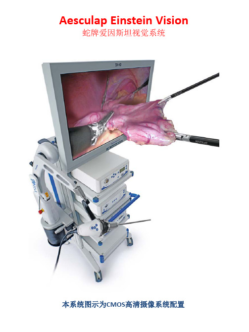
Aesculap Einstein Vision 蛇牌爱因斯坦视觉系统本系统图示为CMOS高清摄像系统配置Aesculap Einstein Vision蛇牌爱因斯坦视觉系统•The following features are valid for all units:•以下标准对所有单元有效:•Universal power supply (100-240 V AC, 50/60 Hz) unless stated otherwise•通用电源(100 -240伏交流电,50/60Hz)除非另有说明•Safety class I (acc. to IEC 60601-1)•电气安全等级(符合IEC 60601-1)•Tested acc. to norm IEC 60601-1, IEC 60601-1-2•测试根据规范IEC 60601-1,IEC 60601-1-2•系统组成•Camera Systems:摄像系统•Light Sources:光源(包括疝气和LED光源)•Documentation:文档生成和打印系统•Full HD Endoscopes:全高清内窥镜•LCD Monitors:液晶显示器•Insufflation:注气系统•Suction and Irrigation:抽吸和冲洗系统•Electrosurgery:电外科手术系统•Endoscopy Carts内镜设备承载车Aesculap Einstein Vision蛇牌爱因斯坦视觉系统(Camera Systems:摄像系统)•Camera Systems:摄像系统:•3-Chip Full HD Camera System•CMOS Full HD Camera System•1-Chip Full HD Camera System•注意:•摄像头系统与镜管和CCU的连接部分的标准化及通用性设计Aesculap Einstein Vision蛇牌爱因斯坦视觉系统3-Chip Full HD Camera System•卓越图像显示效果的最新芯片技术全高清3芯片摄像头系统•提供前所未有质量清晰的全高清图像质量(1920 x 1080像素)•提供图像全高清宽屏16:9图像观看•比标准镜头高达6倍的图像分辨率•先进的高分辨率3芯片技术摄像系统产生三维逼真图像•50 / 60帧每秒的逐行扫描技术提供无延迟图像•专业模式在每一种情况下产生出色的图像•多功能专业的高清摄像机匹配最标准的内窥镜•具备细节增强的光学变焦(2.5倍)•在相机摄像头上集成有容易操作的功能控制按钮•符合人体工程学的摄像头支持无疲劳工作•附件:包括pv460 DVI-D电缆(1X)•附件(需单独订购)•CCU和LED光源之间op942通信电缆Aesculap Einstein Vision蛇牌爱因斯坦视觉系统3-Chip Full HD Camera System技术参数•CCD(英寸):3×1/3”•相机分辨率:1920×1080像素•扫描模式:50/60Hz逐行扫描•模式:6 种预置;3种用户设置•视频信号的输出:2X DVI -D 1080p(50 Hz或60 Hz)•2x HD-SDI 1080i (50/60 Hz)•1x S-Video NTSC/PAL (16:9 屏幕)•摄像头按钮:2个(5功能)•快门速度:1/100—1/50 000每秒•焦距(pv462):13—32毫米。
监控设备配置清单
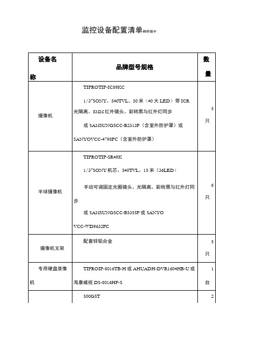
监控设备配置清单枫桥镇中机柜装。
二、硬盘录像机、摄像机一年保换,三年质保服务。
如系统设备发生故障时,中标方必需在一小时内抵达现场解决,不能及时修复的,需提供原品牌、原型号备用设备,保障系统正常运行。
3、为保证视频信号质量,视频电缆半途不能对接。
室外部份所有电缆必需地埋(套上金盾PVC管),控制室内用40*20波达线槽。
实地观察学校场地,合理估算线材,水泥地上施工工具(切割机等)、材料(水泥等)由中标单位自己解决。
4、按照用户具体要求安装、调试好监控系统,整个工程在中标后5天内安装调试完毕。
监控设备配置清单(东一初中监控设备配置清单(东一初中硬盘500GST1只要求:一、所有设备、线材必需是厂家原装生产,原厂原包装到教办,经用户验收合格后再安装。
二、硬盘录像机、摄像机一年保换,三年质保服务。
如系统设备发生故障时,中标方必需在一小时内抵达现场解决,不能及时修复的,需提供原品牌、原型号备用设备,保障系统正常运行。
3、为保证视频信号质量,视频电缆半途不能对接。
室外部份所有电缆必需地埋(套上金盾PVC管),控制室内用40*20波达线槽。
实地观察学校场地,合理估算线材,水泥地上施工工具(切割机等)、材料(水泥等)由中标单位自己解决。
4、按照用户具体要求安装、调试好监控系统,整个工程在中标后5天内安装调试完毕。
监控设备配置清单枫桥镇小)三北RVV2*平方(国标)300摄像机电源线米要求:一、所有设备、线材必需是厂家原装生产,原厂原包装到教办,经用户验收合格后再安装。
二、硬盘录像机、摄像机一年保换,三年质保服务。
如系统设备发生故障时,中标方必需在一小时内抵达现场解决,不能及时修复的,需提供原品牌、原型号备用设备,保障系统正常运行。
3、为保证视频信号质量,视频电缆半途不能对接。
室外部份所有电缆必需地埋(套上金盾PVC管),控制室内用40*20波达线槽。
实地观察学校场地,合理估算线材,水泥地上施工工具(切割机等)、材料(水泥等)由中标单位自己解决。
DataMan

DataMan®300系列快速参考指南2019/03/22预防措施激光,不要直视激光束:2级激光产品。
不遵守这些指示可能导致严l注意—使用任何非此处指定的控件、调节装置或者操作程序,均可能导致有害的辐射泄漏。
l不要尝试保养或修理本产品—应将它退回Cognex进行保养。
l不允许任何非Cognex公司的人员保养、修理或调节本产品。
l除本文档中所述情况外,不要尝试打开或改装本设备。
l不要将激光直接照射或反射到人或反射体。
l如果设备损坏,盖子或密封件丢失或受损时,不要操作本设备。
l仅当所有接口都连上电缆或用密封盖屏蔽时,才能确保IP保护。
本激光产品在整个操作过程中按2类产品设计。
波长650纳米激光功率等级<1mW光束直径<3毫米(孔径)发散度< 1.5毫拉德产品概览1激光瞄准器2照明LED簇3外部照明安装点4安装孔(M3X5毫米)5触发按钮6电源7训练状态8读取/未读取指示灯9网络10错误11峰值计12调谐按钮13以太网14外部灯控制15电源、I/O和RS232DataMan 300配件镜头选件和镜头盖带锁定的10.3毫米M12镜头(DM300-LENS-10)和带锁定的10.3毫米IRM12镜头(DM300-LENS-10-IR)液体镜头模块和带扳手的预对焦10.3毫米或10.3毫米IR M12镜头(DM300-LENS-10LL)、(DM300-LENS-10LL-IR)19毫米液体镜头模块(DM300-LENS-19LL)带锁定的16毫米M12镜头(DM300-LENS-16)24毫米F6液体镜头模块(DM360-LENS-24LL)带镜头垫片和六角扳手的25毫米M12镜头(DM300-LENS-25)(也需要扩展套件)扩展套件(DM300-EXT)DM500C 型镜头盖(DM500-CMTLC-000)(与HPIA 配套使用)DM500镜头盖扩展器(DM500-LNSEXT-000)蓝色(CKR-BP470)、红色(CKR-BP635)、绿色(CKR-BP525)、橙色(CKR-BP590)带通滤波器透明镜头盖(DM300-CLCOV)带白色LED 照明的透明镜头盖(DM300-CLCOV-WHI)通过IEC 62471风险组豁免级标准带红色LED 照明(DM300-DLCOV-RE)、带蓝色LED 照明(DM300-DLCOV-BL)、带红外线LED 照明(DM300-DLCOV-IR)的散射镜头盖,带红色LED 照明(DM300-PLCOV-RE)的偏振镜头盖通过IEC 62471风险组豁免级标准外部灯(红色LED)和大功率照明环形灯(CLRR-R7030G1CLR)背照灯(CLRB-F100100G1)同轴(DOAL)灯(CLRO-K5050G1)聚光灯(CLRS-P14G1)暗场灯(CLRD-D120G1)其他*xx可能是美国、欧洲、英国或日本。
- 1、下载文档前请自行甄别文档内容的完整性,平台不提供额外的编辑、内容补充、找答案等附加服务。
- 2、"仅部分预览"的文档,不可在线预览部分如存在完整性等问题,可反馈申请退款(可完整预览的文档不适用该条件!)。
- 3、如文档侵犯您的权益,请联系客服反馈,我们会尽快为您处理(人工客服工作时间:9:00-18:30)。
产品介绍
品牌:蛇牌型号:GN300
药(械)准字:3253283
生产厂家:德国AESCULAPAGgCO.KG
详细说明:
GN300高频电刀
GN300是函盖多种术式适合全科室使用的多功能电外科工作站
蛇牌特有专利功能
双极电切允许在安全的双极模式下进行敏感组织的切割、分离
比例输出依据脚踏开关灵活调节功率的输出,简化操作,缩短手术间
记忆功能同时记忆4组工作状态
氩气刀插座可结合控制器升级成为氩气
输出特性
双刀笔输出双极电切,单极电切
双极内窥电切功能输出功率0~80W 阻抗700~1300欧姆
具有两种电凝效果柔和电凝、强力电凝
双极电凝功能输出功率0~80W(10W以内0.1步长调节)
阻抗70~250欧姆
自动电切具有自动电压控制的单极切割
高能电切具有自动电弧控制的单极切割、具有汽化电切软件功能
功率峰值系统根据需要释放动态的、以毫秒计算的附加电脉冲,使功率达到需要值
高频功率限值的设置使用向上/向下(UP/DOWN)增量键的HF功率极限调整
电切效果选择可用按键选择4种电切效果及电凝效果
单极内窥混切输出功率0~100W 阻抗250~600欧姆
单极电凝输出功率0~80W 阻抗700~1300欧姆
单极喷凝输出功率0~80W 阻抗70~250欧姆
电源电压:220V
电源频率:50-60HZ
低频漏电:符合IEC601-1标准
高频漏电:符合IEC602-2标准
输出频率:447KHZ
其他特性
自动电切/自动电凝用双插座
通过面板设定的记忆存储功能4种
负极板永久动态监测
适用范围:普外手术、妇科手术、骨科手术、耳鼻喉科手术、胸手术、神经外科手术、显微外科手术、泌尿外科手术(包括前列腺电切和宫腔电切)
切割模式(ATUO CUT):
1.纯切模式(1)1~300W
2.混切模式(2)1~250 W
3.混切模式(3)1~200 W
4.混切模式(4)1~150 W
注:混切模式由(2)至(4)止血效果逐渐增强双极电凝模式(AUTO COAGULATION):
1.双极电凝1~80 W(可0.1W产调节)
单极电凝CONTACT1~120 W
SPRAY 1~80 W
双极电切功能1~80 W。
