3UWC-0.6K;中文规格书,Datasheet资料
三柱接线板规格书

三柱接线板规格书英文文档内容:Three-Prong Extension Cord Specification SheetProduct Overview:The three-prong extension cord is a versatile power solution designed for a variety of applications.It provides a convenient and safe way to extend the reach of your electrical outlets.This specification sheet outlines the key features, technical specifications, and safety information for our three-prong extension cord.Key Features:1.Convenient Extension: The three-prong extension cord allows you to easily connect your appliances and devices to electrical outlets that are too far away.2.Safe Operation: Our extension cord is designed with safety in mind, featuring a grounded plug to reduce the risk of electrical shock and short-circuits.3.Durable Construction: Constructed with high-quality materials, our three-prong extension cord is built to last, ensuring reliable performance even under continuous use.4.Easy to Use: The three-prong extension cord is simple to set up and use, making it ideal for both home and professional use.Technical Specifications:1.Cord Length: 15 feet (4.5 meters)2.Wire Gauge: 16 AWG3.Voltage Rating: 125 Volts4.Amperage Rating: 13 Amps5.Plug Type: Three-prong grounded plug6.Outlet Type: Three-prong grounded outlet7.Jacket Material: PVCSafety Information:1.To prevent accidents and ensure safe operation, always use the three-prong extension cord with grounded outlets.2.Avoid running the extension cord across doorways or under furniture to prevent damage or tripping hazards.3.Do not overload the extension cord by connecting too many appliances or devices.This can cause overheating and potential fire hazards.4.Regularly inspect the extension cord for any signs of wear or damage, such as exposed wires or frayed insulation.If any damage is found, immediately replace the cord to prevent accidents.5.Do not expose the extension cord to extreme temperatures, moisture, or direct sunlight, as this can damage the cord and affect its performance.Please refer to the manufacturer"s instructions for proper installation and use of the three-prong extension cord.中文文档内容:三柱接线板规格书产品概述:三柱接线板是一款多功能电源解决方案,适用于各种应用场景。
DMN601TK-7;中文规格书,Datasheet资料
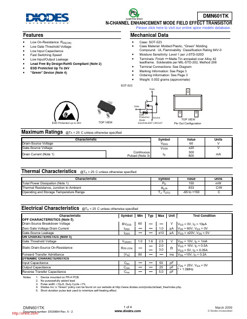
Features• Low On-Resistance: R DS(ON) • Low Gate Threshold Voltage • Low Input Capacitance • Fast Switching Speed• Low Input/Output Leakage• Lead Free By Design/RoHS Compliant (Note 2) • ESD Protected Up To 2kV • "Green" Device (Note 4)Mechanical Data• Case: SOT-523 • Case Material: Molded Plastic, “Green” MoldingCompound. UL Flammability Classification Rating 94V-0 • Moisture Sensitivity: Level 1 per J-STD-020D • Terminals: Finish ⎯ Matte Tin annealed over Alloy 42leadframe. Solderable per MIL-STD-202, Method 208 • Terminal Connections: See Diagram • Marking Information: See Page 3 • Ordering Information: See Page 3 • Weight: 0.002 grams (approximate)Maximum Ratings @T A = 25°C unless otherwise specifiedCharacteristicSymbol Value Units Drain-Source Voltage V DSS 60 VGate-Source Voltage V GSS±20 V Drain Current (Note 1) ContinuousPulsed (Note 3)I D300800mAThermal Characteristics @T A = 25°C unless otherwise specifiedCharacteristicSymbol Value Units Total Power Dissipation (Note 1)P D 150 mW Thermal Resistance, Junction to Ambient R θJA 833 °C/W Operating and Storage Temperature Range T J , T STG-65 to +150°CElectrical Characteristics @T A = 25°C unless otherwise specifiedCharacteristicSymbol Min Typ Max UnitTest ConditionOFF CHARACTERISTICS (Note 5) Drain-Source Breakdown Voltage BV DSS 60 ⎯ ⎯ V V GS = 0V, I D = 10μA Zero Gate Voltage Drain Current I DSS ⎯ ⎯ 1.0 μA V DS = 60V, V GS = 0V Gate-Source LeakageI GSS ⎯ ⎯ ±10 μA V GS = ±20V, V DS = 0V ON CHARACTERISTICS (Note 5) Gate Threshold VoltageV GS(th) 1.0 1.6 2.5 VV DS = 10V, I D = 1mA Static Drain-Source On-Resistance R DS (ON) ⎯ ⎯ ⎯ 2.0 3.0 ΩV GS = 10V, I D = 0.5A V GS = 5V, I D = 0.05A Forward Transfer Admittance |Y fs | 80 ⎯ ⎯ ms V DS =10V, I D = 0.2A DYNAMIC CHARACTERISTICS Input Capacitance C iss ⎯ ⎯ 50 pF V DS = 25V, V GS = 0V f = 1.0MHz Output CapacitanceC oss ⎯ ⎯ 25 pF Reverse Transfer CapacitanceC rss⎯⎯5.0pFNotes: 1. Device mounted on FR-4 PCB. 2. No purposefully added lead.3. Pulse width ≤10μS, Duty Cycle ≤1%4. Diodes Inc.’s “Green” policy can be found on our website at /products/lead_free/index.php.5. Short duration pulse test used to minimize self-heating effect.SOT-523TOP VIEWPin Out ConfigurationESD Protected up to 2kVEQUIVALENT CIRCUITPlease click here to visit our online spice models database.V , DRAIN-SOURCE VOLTAGE (V)Fig. 1 Typical Output CharacteristicsDS I , D R A I N C U R R E N T (A )DFig. 2 Typical Transfer CharacteristicsGS T , CHANNEL TEMPERATURE (°C)Fig. 3 Gate Threshold Voltage vs. Channel T emperaturech 00.51.5I DRAIN CURRENT (A)Fig. 4 Static Drain-Source On-Resistancevs. Drain CurrentD , R , S T A T I C D R A I N -S O U R CE D S (O N)Fig. 5 Static Drain-Source On-Resistancevs. Drain CurrentDR , S T A T I C D R A I N -S O U R C E D S (O N )V GATE SOURCE VOLTAGE (V)Fig. 6 Static Drain-Source On-Resistancevs. Gate-Source VoltageGS,R , S T A T I C D R A I N -S O U R C E O N -R E S I S T A N C E ()D S (O N )ΩFig. 7 CH Static Drain-Source On-State Resistancevs. Channel T emperatureR , S T A T I C D R A I N -S O U R C E D S (O N )1I , R E V E R S E D R A I N C U R RE N T (A )D R 1I , DRAIN CURRENT (A)D Fig.10 Forward Transfer Admittancevs. Drain CurrentOrdering Information (Note 6)Part Number Case Packaging DMN601TK-7SOT-523 3000/Tape & ReelNotes: 6. For packaging details, go to our website at /datasheets/ap02007.pdf.Marking InformationDate Code KeyYear 2005 2006 2007 2008 2009 2010 2011 2012 Code S T U V W X Y ZMonth Jan Feb Mar Apr May Jun Jul Aug Sep Oct Nov Dec Code 1 2 3 4 5 6 7 8 9 O N DK7K = Product Type Marking Code YM = Date Code Marking Y = Year (ex: S = 2005) M = Month (ex: 9 = September) K7K YMPackage Outline DimensionsSuggested Pad LayoutIMPORTANT NOTICEDiodes Incorporated and its subsidiaries reserve the right to make modifications, enhancements, improvements, corrections or other changes without further notice to any product herein. Diodes Incorporated does not assume any liability arising out of the application or use of any product described herein; neither does it convey any license under its patent rights, nor the rights of others. The user of products in such applications shall assume all risks of such use and will agree to hold Diodes Incorporated and all the companies whose products are represented on our website, harmless against all damages.LIFE SUPPORTDiodes Incorporated products are not authorized for use as critical components in life support devices or systems without the expressed written approval of the President of Diodes Incorporated.SOT-523Dim Min Max Typ A 0.15 0.30 0.22 B 0.75 0.85 0.80 C 1.45 1.75 1.60 D ⎯ ⎯ 0.50 G 0.90 1.10 1.00 H 1.50 1.70 1.60 J 0.00 0.10 0.05 K 0.60 0.80 0.75 L 0.10 0.30 0.22 M 0.10 0.20 0.12 N 0.45 0.65 0.50α0° 8° ⎯ All Dimensions in mmDimensions Value (in mm)Z1.8 X 0.4 Y 0.51 C 1.3 E 0.7X EYCZ分销商库存信息: DIODESDMN601TK-7。
HGTG30N60B3;中文规格书,Datasheet资料

Gate to Emitter Plateau Voltage On-State Gate Charge
VGEP QG(ON)
IC = IC110, VCE = 0.5 BVCES IC = IC110, VCE = 0.5 BVCES VGE = 15V VGE = 20V
-
7.2 170 230 36 25 137 58 500 550 680
Features
• 60A, 600V, TC = 25oC • 600V Switching SOA Capability • Typical Fall Time. . . . . . . . . . . . . . . . . 90ns at TJ = 150oC • Short Circuit Rating • Low Conduction Loss
VCE(SAT)
IC = IC110, VGE = 15V
Gate to Emitter Threshold Voltage Gate to Emitter Leakage Current Switching SOA
VGE(TH) IGES SSOA
IC = 250µA, VCE = VGE VGE = ±20V TJ = 150oC, RG = 3Ω, VGE = 15V, L = 100µH
©2004 Fairchild Semiconductor Corporation
HGTG30N60B3 Rev. B3
/
HGTG30N60B3
Absolute Maximum Ratings
TC = 25oC, Unless Otherwise Specified HGTG30N60B3 Collector to Emitter Voltage . . . . . . . . . . . . . . . . . . . . . . . . . . . . . . . . . . . . . . . . . . . . . .BVCES Collector Current Continuous At TC = 25oC . . . . . . . . . . . . . . . . . . . . . . . . . . . . . . . . . . . . . . . . . . . . . . . . . . . . . . . . . IC25 At TC = 110oC . . . . . . . . . . . . . . . . . . . . . . . . . . . . . . . . . . . . . . . . . . . . . . . . . . . . . . . IC110 Collector Current Pulsed (Note 1) . . . . . . . . . . . . . . . . . . . . . . . . . . . . . . . . . . . . . . . . . . . ICM Gate to Emitter Voltage Continuous. . . . . . . . . . . . . . . . . . . . . . . . . . . . . . . . . . . . . . . . . VGES Gate to Emitter Voltage Pulsed . . . . . . . . . . . . . . . . . . . . . . . . . . . . . . . . . . . . . . . . . . . .VGEM Switching Safe Operating Area at TJ = 150oC (Figure 2) . . . . . . . . . . . . . . . . . . . . . . . SSOA Power Dissipation Total at TC = 25oC . . . . . . . . . . . . . . . . . . . . . . . . . . . . . . . . . . . . . . . . . PD Power Dissipation Derating TC > 25oC . . . . . . . . . . . . . . . . . . . . . . . . . . . . . . . . . . . . . . . . . . Reverse Voltage Avalanche Energy . . . . . . . . . . . . . . . . . . . . . . . . . . . . . . . . . . . . . . . . . EARV Operating and Storage Junction Temperature Range . . . . . . . . . . . . . . . . . . . . . . . . TJ, TSTG Maximum Lead Temperature for Soldering . . . . . . . . . . . . . . . . . . . . . . . . . . . . . . . . . . . . . TL Short Circuit Withstand Time (Note 2) at VGE = 12V. . . . . . . . . . . . . . . . . . . . . . . . . . . . . .tSC Short Circuit Withstand Time (Note 2) at VGE = 10V. . . . . . . . . . . . . . . . . . . . . . . . . . . . . .tSC 60 30 220 ±20 ±30 60A at 600V 208 1.67 100 -55 to 150 260 4 10 W W/oC mJSymbolC
ELT3KN020C中文资料(PANASONIC)中文数据手册「EasyDatasheet - 矽搜」
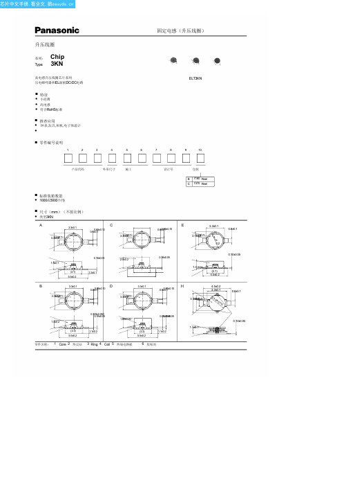
3.3±0.1 3.31±.02.±20.1
0.6±00.8.15±0.10
H
4.5±0.2 3.3±0.1
3.12±.051.±2.02.±10.1
2.73± 0.10
0.8±0.1
1.4±0.2
0.125±0.050 0.18±0.05
1.65±0.20
0.205.±108.±005.05
(3.3) 5.5±0.2
电感
(mH) 14.00 20.00
1.00 1.50 0.82 14.00 3.80 2.50 30.00 35.00 50.00 25.00 10.00 1.00 2.50 1.00 2.00 1.00 4.00 0.47 0.56 0.68 2.30 2.00 30.00 7.50 4.00 14.00 20.00 12.00 0.68 0.82 1.10 2.00 4.00 0.33 0.56 0.47 1.10 4.00 1.10
P
P
0D
t
t
2.0
4.0
1.5
0.3
2.6
● 标题部分,虚位以待
Leader part 200 min.
Tape end
50 min. Vacant position
50 min. Vacant position
■ 应用图示例
Vo +1.5 V
SC
Vo
Vi Vi
For making sound
+3.0 V V2
E
3.3±0.1
0.8±0.1
3.11±.02.±20.1
f3. 1± 0.2
1.5±0.1
(3.1) 5.5±0.2
NZH3V0B,115;NZH10C,115;NZH8V2B,115;NZH7V5C,115;NZH6V2B,115;中文规格书,Datasheet资料
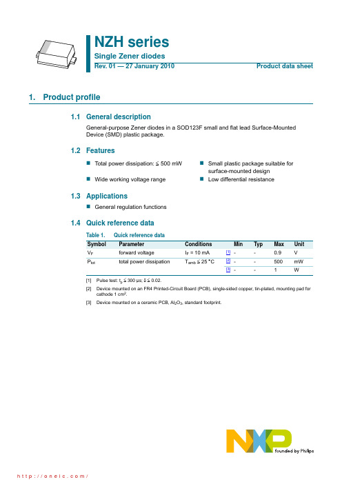
thermal resistance from junction to solder point
Min Typ Max Unit
[1] -
-
250 K/W
[2] -
-
125 K/W
[3] -
-
70 K/W
[1] Device mounted on an FR4 PCB, single-sided copper, tin-plated, mounting pad for cathode 1 cm2. [2] Device mounted on a ceramic PCB, Al2O3, standard footprint. [3] Soldering point of cathode tab.
Version SOD123F
Table 4. Marking codes
Type number
Marking code
NZH3V0B
CH
NZH3V3A
CJ
NZH3V6B
CK
NZH3V9B
CL
NZH4V3B
CM
NZH4V7B
CN
NZH5V1B
CP
NZH5V6B
CQ
NZH6V2B
CR
NZH6V8B
CS
5. Limiting values
Table 5. Limiting values In accordance with the Absolute Maximum Rating System (IEC 60134).
Symbol Parameter
Conditions
Min
Max Unit
IF Ptot
NZHxxx
摩恩孙U6WR3系列6W隔离DC-DC转换器产品说明书

6W,Ultra wide input isolated ®ulateddual/single output,DIP package,DC/DC converte r CBPatent Protection RoHSFEATURES ●Wide input voltage range (4:1)●High efficiency up to 88%●No-load power consumption as low as 0.12W ●Isolation voltage :3K VDC●Operating temperature range:-40℃to +85℃●Input under-voltage protection,output short circuit ,over-current,over-voltage protection●Meet CISPR32/EN55032CLASS A,without external components●International standard pin-out●IEC60950,UL60950,EN60950approvalURF_P-6WR3&URF_P-6WR3series are isolated 6W DC-DC converters with 4:1input voltage.They feature efficiency up to 88%,3000VDC isolation voltage,operating temperature of -40℃to +85℃,solation voltage of 3000VDC,output over-voltage protection and output short circuit protection with the bare component in compliance with CISPR32/EN55032CLASS A;these products are widely used in fields such as industrial control,electric power,instruments and communication.Selection GuideCertificationPart No.Input Voltage (VDC)OutputEfficiency(%,Min./Typ.)②@Full LoadMax.CapacitiveLoad ③(µF)Nominal(Range)Max.①Output Voltage (VDC)Output Current (mA)(Max./Min.)UL/CE/CBURE2405P-6WR324(9-36)40±5±600/078/80680URE2412P-6WR3±12±250/082/84330URE2415P-6WR3±15±200/083/85220URF2403P-6WR3 3.31500/077/792200URF2405P-6WR351200/080/822200URF2409P-6WR39667/083/851000URF2412P-6WR312500/084/86680URF2415P-6WR315400/086/88680URF2424P-6WR324250/085/87680URF4803P-6WR348(18-75)803.31500/077/792200URF4805P-6WR351200/081/832200URF4812P-6WR312500/085/87680URF4815P-6WR315400/086/88680URF4824P-6WR324250/085/87680Notes :1The input voltage shoud not exceed the maximun rating,or it maight cause unrecoverable damages;2Efficiency is measured In nominal input voltage and rated output load;3The capacitive loads of positive and negative outputs are identical.Input SpecificationsItemOperating ConditionsMin.Typ.Max.UnitInput Current (full load /no-load)24VDC Input3.3V output --261/5268/8mAOther output --297/5320/848VDC Input3.3V output --131/4134/7Other output--146/4154/7Reflected Ripple Current24VDC Input --20--mA48VDC Input --20--Input impulse Voltage (1sec.max.)24VDC Input -0.7--50VDC48VDC Input -0.7--100Starting Voltage24VDC Input ----948VDC Input ----18Input Under-voltage Protection24VDC Input 5.5 6.5--48VDC Input1215.5--Starting Time Nominal input&constant resistance load--10--msInput Filter Pi filter Hot PlugUnavailableOutput SpecificationsItemOperating ConditionsMin.Typ.Max.UnitOutput Voltage Accuracy 5%-100%load --±1±3%0%-5%loadSingle output --±1±3Dual output--±2±5Balance of Output Voltage Dual output,balanced load --±0.5±1.5Line Regulation Full load,the input voltage is from low voltage to high voltage Positive output --±0.2±0.5Negative output --±0.5±1Load Regulation ①5%-100%loadPositive output --±0.5±1Negative output --±0.5±1.5Cross Regulation Dual output,main circuit with 50%load,auxiliary circuit with 10%-100%load ----±5Transient Recovery Time 25%load step change --300500µs Transient Response Deviation --±3±5%Temperature Drift Coefficient Full load----±0.03%/℃Ripple&Noise ②20MHz bandwidth,5%-100%load --85120mV p-p Over-voltage Protection Input voltage range 110--160%Vo Over-current Protection Input voltage range 24V output 110220290%IoOthers110140190Short circuit ProtectionInput voltage rangeContinuous,self-recoveryNote:①When testing from 0%to100%load working conditions ,load regulation index of ±5%;②0%-5%load ripple&Noise is no more than 5%Vo.Ripple and noise are measured by “parallel cable”method,please see DC-DC Converter Application Notes for specific operation.General SpecificationsItemOperating ConditionsMin.Typ.Max.Unit Isolation Voltage Input-output,with the test time of 1minute and the leak current lower than 1mA3000----VDC Isolation Resistance Input-output,insulation voltage 500VDC 1000----M ΩIsolation Capacitance Input-output,100KHz/0.1V--1000--pF Operating Temperature Derating if the temperature is ≥71℃(see Fig.1)-40--85℃Storage Temperature -55--125Storage Humidity Non-condensing5--95%RH Pin Welding Resistance Temperature Welding spot is 1.5mm away from the casing,10seconds----300℃Vibration10-55Hz,10G,30Min.along X,Y and ZSwitching Frequency PWM mode--300--KHz MTBFMIL-HDBK-217F@25℃1000----K hoursNote:*This series of products using the technique of reducing frequency.The switching frequency is test at full load;when the load is below 50%,the switching frequency decreases with decreasing load.Physical SpecificationsCasing Material Black flame-retardant heat-proof plastic (UL94V-0)Package Dimensions 31.60*20.30*10.20mm Weight13.00g(Typ.)Cooling methodFree air convectionEMC SpecificationsEMICECISPR32/EN55032CLASS A (Bare component)/CLASS B (see Fig.3-②for recommended circuit)RE CISPR32/EN55032CLASS A (Bare component)/CLASS B (see Fig.3-②for recommended circuit)EMSESD IEC/EN61000-4-2Contact ±4KV perf.Criteria B RS IEC/EN61000-4-310V/mperf.Criteria A EFTIEC/EN61000-4-4±2KV (see Fig.3-①for recommended circuit)perf.Criteria B Surge IEC/EN61000-4-5±2KV (see Fig.3-①for recommended circuit)perf.Criteria B CSIEC/EN61000-4-63Vr.m.sperf.Criteria A Immunities of voltage dip,drop and short interruptionIEC/EN61000-4-290-70%perf.CriteriaBProduct Characteristic CurveOperat ing Temperat ure()℃ Temperature Derating C urveO u t p u t P o w e r P e r c e n t a g e (%)-400407185120806010012040200Safe Operating AreaFig.1Design Reference1.Typical applicationAll the DC/DC converters of this series are tested according to the recommended circuit (see Fig.2)before delivery.If it is required to further reduce input and output ripple,properly increase the input &output of additional capacitors Cin and Cout or select capacitors of low equivalent impedance provided that the capacitance is no larger than the max.capacitive load of the product.SingleVinGND+Vo0VDCCinDC CoutDualV inGND+Vo 0V CinCout DC DC-VoCoutFig.2Vin(VDC)Cin(µF)Cout(µF)24100104810~47102.EMC solution-recommended circuitURE_P-6WR3&URF_P-6WR3:Fig.3-①URE_P-6WR3:URF_P-6WR3:Fig.3-②Notes:Part ①in the Fig.3is used for EMS test and part ②for EMI filtering;selected based on needs.Parameter descriptionURE_P-6WR3Model Vin:24VFUSE Choose according to actual input currentC01000µF/50V C11µF/50VC3Refer to the Cout in Fig.2LDM1 4.7µH CY1、CY21nF/3KVParameter descriptionURF_P-6WR3Model Vin:24V Vin:48V FUSE Choose according to actual input currentC01000µF/50V 680µF/100V C1,C2 2.2µF/50V2.2µF/100VLCM 2.2mH,recommended to use MORNSUN’sFL2D-30-222C3Refer to the Cout in Fig.23.It is not allowed to connect modules output in parallel to enlarge the power4.For more information please find DC-DC converter application notes on Dimensions and Recommended LayoutNote:1.Packing information please refer to Product Packing Information which can be downloaded from .ThePacking bag number of Horizontal package:58210008;2.The max.capacitive load should be tested within the input voltage range and under full load conditions;3.Unless otherwise specified,data in this datasheet should be tested under the conditions of Ta=25℃,humidity<75%RH when inputtingnominal voltage and outputting rated load;4.The recommended unbalance degree of the dual output module load is≤±5%;if the degree exceeds±5%,the product performancecannot be guaranteed to comply with all parameters in the datasheet.Please contact our technicians directly for specific information;5.All index testing methods in this datasheet are based on our Company’s corporate standards;6.The performance indexes of the product models listed in this datasheet are as above,but some indexes of non-standard modelproducts will exceed the above-mentioned requirements,and please directly contact our technicians for specific information;7.We can provide product customization service;8.Products are related to laws and regulations:see"Features"and"EMC";9.Our products shall be classified according to ISO14001and related environmental laws and regulations,and shall be handled byqualified units.Mornsun Guangzhou Science&Technology Co.,Ltd.Address:No.5,Kehui St.1,Kehui Development Center,Science Ave.,Guangzhou Science City,Luogang District,Guangzhou,P.R.China Tel:86-20-38601850-8801Fax:86-20-38601272E-mail:****************。
3NC3430-1U datasheet说明书
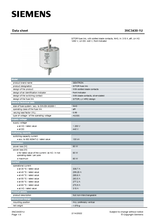
3NC34301U Page 2/3
2/14/2022
Subject to change without notice © Copyright Siemens
3NC34301U Page 3/3
2/14/2022
Subject to change without notice © Copyright Siemens
NH3 aR 0.95 AC/DC
1 250 V 440 V
100 kA 80 W 80 W 80 W
308.7 A 299.25 A 289.8 A 283.5 A 277.2 A 270.9 A 315 A
Not non-interchangeable
Any, preferably vertical 1 070 g
2/14/2022
Subject to change without notice © Copyright Siemens
Environmental conditions ambient temperature / during operation ● minimum ● maximum environmental category General Product Approval
Product details product description
Mechanical Design mounting position net weight
3NC34301U Page 1/3
SENTRON SITOR fuse link With slotted blade contacts front indicator With blade contacts, silver-plated SITOR, LV HRC design
LC03-6R2G, 规格书,Datasheet 资料
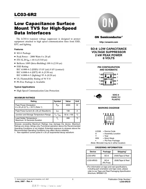
LC03-6R2Low Capacitance Surface Mount TVS for High-Speed Data InterfacesThe LC03-6 transient voltage suppressor is designed to protect equipment attached to high speed communication lines from ESD,EFT, and lighting.Features•ăSO-8 Package•ăPeak Power - 2000 Watts 8 x 20 m S •ăITU K.20 I PP = 40 A (5/310 m s)•ăBellcore 1089 (Intra-Building) 100 A (2/10 m s)•ăESD Rating:IEC 61000-4-2 (ESD) 15 kV (air) 8 kV (contact)IEC 61000-4-4 (EFT) 40 A (5/50 ns)IEC 61000-4-5 (lighting) 95 A (8/20 m s)•ăUL Flammability Rating of 94 V-0•ăPb-Free Package is AvailableTypical Applications•ăHigh Speed Communication Line ProtectionMAXIMUM RATINGSRatingSymbol Value Unit Peak Power Dissipation8 x 20 m S @ T A = 25°C (Note 1)P pk 2000WPeak Pulse Current (8 x 20 m S Waveform)I PP 100A Junction and Storage Temperature Range T J , T stg -55 to +150°C Lead Solder Temperature -Maximum 10 Seconds DurationT L260°CStresses exceeding Maximum Ratings may damage the device. MaximumRatings are stress ratings only. Functional operation above the Recommended Operating Conditions is not implied. Extended exposure to stresses above the Recommended Operating Conditions may affect device reliability.1.Non-repetitive current pulse 8 x 20 m S exponential decay waveformSO-8 LOW CAPACITANCE VOLTAGE SUPPRESSOR 2 kW PEAK POWER6 VOLTS12348765PIN CONFIGURATION AND SCHEMATICMARKING DIAGRAMSOIC-8CASE 751PLASTIC†For information on tape and reel specifications,including part orientation and tape sizes, please refer to our Tape and Reel Packaging Specification Brochure, BRD8011/D.8LC036= Device Code A = Assembly Location Y = Year WW = Work Week G = Pb-Free Package(Note: Microdot may be in either location)Device Package ORDERING INFORMATIONShipping †LC03-6R2SO-82500/T ape & Reel LC03-6R2GSO-8(Pb-Free)2500/T ape & ReelELECTRICAL CHARACTERISTICSCharacteristicSymbol Min Typ Max Unit Reverse Breakdown Voltage @ I t = 1.0 mA V BR 6.8--V Reverse Leakage Current @ V RWN = 5.0 VI R N/A -20m A Maximum Clamping Voltage @ I PP = 50 A, 8 x 20 m S V C N/A -15V Maximum Clamping Voltage @ I PP = 100 A, 8 x 20 m S V C N/A -20V Between I/O Pins and Ground @ V R = 0 V, 1.0 MHz Capacitance -1625pF Between I/O Pins @ V R = 0 Volts, 1.0 MHzCapacitance-8.012pFTYPICAL CHARACTERISTICS-80010Figure 1. Reverse Voltage versus Temperature-40T, TEMPERATURE (°C)801404Figure 2. Reverse Leakage versusTemperatureV Z , R E V E R S E V O L T A G E (V )161412108642-80-6020100T, TEMPERATURE (°C)14040120286120I R , R E V E R S E L E A K A G E (m A)-6020-2010060-40-20406080Figure 3. 8 x 20 ms Pulse Waveform1009080706050403020100t, TIME (m s)% O F P E A K P U L S E C U R R E N TFigure 4. Clamping Voltage versus Peak PulseCurrent201812108640I PP , PEAK PULSE CURRENT (A)V C , C L A M P I N G V O L T A G E (V )21416APPLICATIONS INFORMATIONThe LC03-6 ON Semiconductor's device is a TVS Diode array designed to protect sensitive electronics such as communications systems, computers, and computer peripherals against damage due to transient overvoltage conditions caused by lightning, electrostatic discharge (ESD), and electrical fast transients (EFT). Because of its relative low capacitance (<25 pf), it can be used in high speed I/O data lines such as USB 1.1 ports.The integrated design of the LC03-6 device offers high surge rating, low capacitance steering diodes, and a TVS diode integrated in a single package (SO-8). In addition, this device offers compliance to Bellcore 1089 requirements (intra-building).LC03-6 Device's Configurations OptionsProtection of Two High-speed I/O Data LinesThe LC03-6 device is able to protect two high speed data lines against transient overvoltage conditions by driving them to a fixed reference point for clamping purposes.Depending in the application's requirements, the LC03-6device can be configured for protection in either differential mode (Line-to-Line) or common mode (Line-to-ground).The Figure 5 shows the connection for Differential mode (Line-to-Line) and Common mode (Line-to-G round)protection. The inputs and outputs of the I/O data lines are connected at terminals 1 to 8, and 4 to 5 while the terminals 2, 3, 6 and 7 are connected to ground; for better performance,it is recommended to minimize parasitic inductances by using ground planes and minimizing the PCB trace lengths for the ground return connections.Figure 5. Configuration for Differentialand Common Mode ProtectionLC03-6Line 1OutLine 2OutLine 1InLine 2In If differential protection is required by some particular applications, then the configuration for differential protection is made as shown in the Figure 6:Figure 6. Configuration for DifferentialProtection (Line-to-Line)LC03-6Line 1OutLine 2OutLine 1InLine 2In T1/E1 Linecard Protection (Intra-Building)The Figure 7 shows a typical schematic for a T1/E1 line card protection circuit. The LC03-6 device is connected between Tip and Ring on the transmit and receive line pairs.it provides protection to metallic and common mode lightning surges per Bellcore 1089 intra-building (For further information, see Bellcore 1089 standard). A metallic voltage is defined as a difference of potential between the T and R terminals of a telecommunications pair. Currents caused by lightning, in the absence of protector operation and with balanced terminal equipment and telecommunications loop,cause Tip and Ring conductors to attain the same potential hence do not produce metallic transients. Common mode surges are suppressed by the isolation of the transformer.Figure 7. Typical T1 Line Card ProtectionESD Protection in USB 1.1 Port ApplicationsAs we know, a USB port is composed of four lines. The lines D+ and D- are used for bi-directional data transmission, and the remaining two lines are reserved for bus voltage and ground. Since USB is a hot plugging and unplugging system, all its four lines have the risk to receive ESD conditions in the real field of the application.Typical ESD protection techniques are commonly formed by the combination of different discrete semiconductor products which make this technique obsolete and non-ef ficient because the interconnections of the discrete devices increase the parasitic inductance effects during atransient condition which reduces significantly the performance of the ESD protection circuit. The LC03-6device provides a unique TVS Diode array designed to protect two I/O data lines (single USB port) against damage due to ESD conditions or transient voltage conditions.Because of its low capacitance, it can be used in high speed I/O data lines such as USB 1.1 components. In addition to its low capacitance characteristics, the LC03-6 device from ONĂSemiconductor complies with the most common industrial standards for ESD, EFT and surge protection:IEC61000-4-2, IEC61000-4-4, IEC61000-4-5.PACKAGE DIMENSIONSSOIC-8 NB CASE 751-07ISSUE AHNOTES:1.DIMENSIONING AND TOLERANCING PER ANSI Y14.5M, 1982.2.CONTROLLING DIMENSION: MILLIMETER.3.DIMENSION A AND B DO NOT INCLUDE MOLD PROTRUSION.4.MAXIMUM MOLD PROTRUSION 0.15 (0.006)PER SIDE.5.DIMENSION D DOES NOT INCLUDE DAMBAR PROTRUSION. ALLOWABLE DAMBARPROTRUSION SHALL BE 0.127 (0.005) TOTAL IN EXCESS OF THE D DIMENSION AT MAXIMUM MATERIAL CONDITION.6.751-01 THRU 751-06 ARE OBSOLETE. NEW STANDARD IS 751-07.DIM A MIN MAX MIN MAX INCHES4.805.000.1890.197MILLIMETERS B 3.80 4.000.1500.157C 1.35 1.750.0530.069D 0.330.510.0130.020G 1.27 BSC 0.050 BSC H 0.100.250.0040.010J 0.190.250.0070.010K 0.40 1.270.0160.050M 0 8 0 8 N 0.250.500.0100.020S5.806.200.2280.244MYM0.25 (0.010)YM0.25 (0.010)Z SXS____0.60.024ǒmm inchesǓSCALE 6:1*For additional information on our Pb-Free strategy and solderingdetails, please download the ON Semiconductor Soldering and Mounting Techniques Reference Manual, SOLDERRM/D.SOLDERING FOOTPRINT*ON Semiconductor and are registered trademarks of Semiconductor Components Industries, LLC (SCILLC). SCILLC reserves the right to make changes without further notice to any products herein. SCILLC makes no warranty, representation or guarantee regarding the suitability of its products for any particular purpose, nor does SCILLC assume any liability arising out of the application or use of any product or circuit, and specifically disclaims any and all liability, including without limitation special, consequential or incidental damages.“Typical” parameters which may be provided in SCILLC data sheets and/or specifications can and do vary in different applications and actual performance may vary over time. All operating parameters, including “Typicals” must be validated for each customer application by customer's technical experts. SCILLC does not convey any license under its patent rights nor the rights of others. SCILLC products are not designed, intended, or authorized for use as components in systems intended for surgical implant into the body, or other applications intended to support or sustain life, or for any other application in which the failure of the SCILLC product could create a situation where personal injury or death may occur. Should Buyer purchase or use SCILLC products for any such unintended or unauthorized application, Buyer shall indemnify and hold SCILLC and its officers, employees, subsidiaries, affiliates,and distributors harmless against all claims, costs, damages, and expenses, and reasonable attorney fees arising out of, directly or indirectly, any claim of personal injury or death associated with such unintended or unauthorized use, even if such claim alleges that SCILLC was negligent regarding the design or manufacture of the part. SCILLC is an Equal Opportunity/Affirmative Action Employer. This literature is subject to all applicable copyright laws and is not for resale in any manner.PUBLICATION ORDERING INFORMATION。
3.2V10AH电池组中文规格书
1.适用范围
本规格书描述的是可充电聚合物锂离子电池的产品性能指标。
2.单只型号:PF69153257-100000mah
3.尺寸:
项目
描述
尺寸
T
厚度
65.0mm max
W
宽度
153mm max
L
长度
253mm max
B
极柱高度
16±1mm
4.规格
废弃之电池应用绝缘纸包住电极,以防起火、爆炸
5
热冲击安全性能
不起火、不爆炸
测量电池的初始状态,电池标准充电后,放置于热箱中,并与热电偶相连,温度以(5±2℃)/min的速率升至150±2℃并保温30Min。观察电池外观变化
5.3环境适应性能
序号
项目
标准
测试方法
1
热循环性能
不漏液、不冒烟、不起火、
不爆炸。
电池标准充电后,在环境温度为75±2℃℃的条件下开路放置48h,后在-20℃条件下开路放置6h,后在室温条件下开路放置24h。观察电池外观变化。
5.2安全性能
序号
项目
标准
测试方法
1
过充性能
不爆炸、不起火,
最高温度<130℃
电池标准充电后,测量电池的初始状态,保证电池状态正常(下同),以3C5A电流充电至10.0V,然后转恒压充电至截至电流0.01C5A时终止,观察电池的温度及外观变化。
2
过放性能
不起火、不爆炸
电池标准充电后,测量电池初始状态,以0.2C5A进行放电至2.0V,然后用10Ω的电阻将电池正负极相连,搁置14天。观察电池外观变化。
使用规定的充电器
MRFG35002N6R5;中文规格书,Datasheet资料
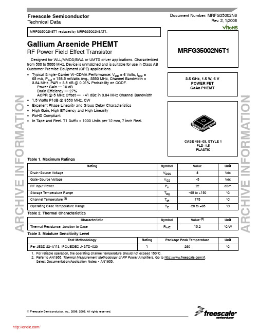
A R C H I V E I N F O R M A T I O NA R C H I V E I N FMRFG35002N6T1 replaced by MRFG35002N6AT1.Gallium Arsenide PHEMTRF Power Field Effect TransistorDesigned for WLL/MMDS/BWA or UMTS driver applications. Characterized from 500 to 5000 MHz. Device is unmatched and is suitable for use in Class AB Customer Premise Equipment (CPE) applications.•Typical Single-Carrier W-CDMA Performance: V DD = 6 Volts, I DQ = 65 mA, P out = 158.5 mWatts Avg., 3550 MHz, Channel Bandwidth = 3.84 MHz, PAR = 8.5 dB @ 0.01% Probability on CCDF.Power Gain — 10 dB Drain Efficiency — 27%ACPR @ 5 MHz Offset — -41 dBc in 3.84 MHz Channel Bandwidth • 1.5 Watts P1dB @ 3550 MHz, CW•Excellent Phase Linearity and Group Delay Characteristics •High Gain, High Efficiency and High Linearity •RoHS Compliant.•In Tape and Reel. T1 Suffix = 1000 Units per 12 mm, 7 inch Reel.Table 1. Maximum RatingsRatingSymbol Value Unit Drain-Source Voltage V DSS 8Vdc Gate-Source Voltage V GS -5Vdc RF Input PowerP in 22dBm Storage Temperature Range T stg -65 to +150°C Channel Temperature (1)T ch 175°C Operating Case Temperature RangeT C-20 to +85°CTable 2. Thermal CharacteristicsCharacteristicSymbol Value (2)Unit Thermal Resistance, Junction to CaseR θJC15.2°C/WTable 3. Moisture Sensitivity LevelTest MethodologyRating Package Peak TemperatureUnit Per JESD 22-A113, IPC/JEDEC J-STD-0201260°C1.For reliable operation, the operating channel temperature should not exceed 150°C.2.Refer to AN1955, Thermal Measurement Methodology of RF Power Amplifiers. Go to /rf. Select Documentation/Application Notes - AN1955.Document Number: MRFG35002N6Rev. 2, 1/2008Freescale Semiconductor Technical Data3.5 GHz, 1.5 W, 6 V POWER FET GaAs PHEMTMRFG35002N6T1A R C H I V E I N F OR M A T I O NA R C H I V E I N F O R M A T I O NMRFG35002N6T1Table 4. Electrical Characteristics (T C = 25°C unless otherwise noted)CharacteristicSymbol Min Typ Max Unit Saturated Drain Current(V DS = 3.5 Vdc, V GS = 0 Vdc)I DSS — 1.7—Adc Off State Leakage Current(V GS = -0.4 Vdc, V DS = 0 Vdc)I GSS —< 1.0100μAdc Off State Drain Current(V DS = 6 Vdc, V GS = -2.5 Vdc)I DSO ——600μAdc Off State Current(V DS = 28.5 Vdc, V GS = -2.5 Vdc)I DSX —< 1.09mAdc Gate-Source Cut-off Voltage (V DS = 3.5 Vdc, I DS = 8.7 mA)V GS(th)-1.2-0.9-0.7Vdc Quiescent Gate Voltage(V DS = 6 Vdc, I D = 65 mA)V GS(Q)-1.1-0.8-0.6VdcFunctional Tests (In Freescale Test Fixture, 50 ohm system) V DD = 6 Vdc, I DQ = 65 mA, P out = 158.5 mW Avg., f = 3550 MHz,Single-Carrier W-CDMA, 3.84 MHz Channel Bandwidth Carrier. ACPR measured in 3.84 MHz Channel Bandwidth @ ±5 MHz Offset. PAR = 8.5 dB @ 0.01% Probability on CCDF.Power Gain G ps 8.510—dB Drain Efficiencyh D 2327—%Adjacent Channel Power RatioACPR—-41-38dBcTypical RF Performance (In Freescale Test Fixture, 50 οhm system) V DD = 6 Vdc, I DQ = 65 mA, f = 3550 MHz Output Power, 1 dB Compression Point, CWP 1dB—1.5—WA R C H I V E I N F O R M A T I O NA R C H I V E I N F O R M A T I ONMRFG35002N6T1Figure 1. MRFG35002N6 Test Circuit SchematicZ80.420″ x 0.150″Microstrip Z90.150″ x 0.068″Microstrip Z100.290″ x 0.183″Microstrip Z120.044″ x 0.115″Microstrip Z130.044″ x 0.894″Microstrip PCBRogers 4350, 0.020″, εr = 3.5Z1, Z140.044″ x 0.125″Microstrip Z20.044″ x 0.500″Microstrip Z30.044″ x 0.052″Microstrip Z40.468″ x 0.010″Microstrip Z50.468″ x 0.356″ Microstrip Z6, Z110.015″ x 0.549″Microstrip Z70.031″ x 0.259″MicrostripTable 5. MRFG35002N6 Test Circuit Component Designations and ValuesPartDescriptionPart Number Manufacturer C1, C2413 pF Chip Capacitors100A130JP150XATCC2Not UsedC3 1.2 pF Chip Capacitor 08051J1R2BBT AVX C40.7 pF Chip Capacitor 08051J0R7BBT AVX C5, C6, C21, C22 5.6 pF Chip Capacitors 08051J6R8BBT AVX C7, C2010 pF Chip Capacitors 100A100JP150X ATC C8, C19100 pF Chip Capacitors 100A101JP150X ATC C9, C18100 pF Chip Capacitors 100B101JP500X ATC C10, C171000 pF Chip Capacitors 100B102JP50X ATC C11, C160.1 μF Chip Capacitors CDR33BX104AKWS Kemet C12, C1539K pF Chip Capacitors 200B393KP50XATC C13, C1410 μF Chip Capacitors GRM55DR61H106KA88B Kemet C230.2 pF Chip Capacitor 08051J0R2BBTAVXR1100 Ω, 1/4 W Chip ResistorA R C H I V E I N F O R M A T I O NA R C H I V E I N F O R M A T I ONMRFG35002N6T1Figure 2. MRFG35002N6 Test Circuit Component LayoutA R C H I V E I N F O R M A T I O NA R C H I V E I N F O R M A T I ONMRFG35002N6T1TYPICAL CHARACTERISTICSηD , D R A I N E F F I C I E N C Y (%)G T , T R A N S D U C E R G A I N (d B )P out , OUTPUT POWER (dBm)Figure 3. Transducer Gain and Drain Efficiency versus Output Power3041400501210408306205101015202530−60−20−200P out , OUTPUT POWER (dBm)Figure 4. Single-Carrier W-CDMA ACPR and Input Return Loss versus Output PowerA C P R , A D J A C E N T C H A N N E L P O W E R R A T I O (dB c )I N P U T R E T U R N L O S S (d B )I R L ,−5−30−40−50−156−10121824NOTE:All data is referenced to package lead interface. ΓS and ΓL are the impedances presented to the DUT.All data is generated from load pull, not from the test circuit shown.A R C H I V E I N F O R M A T I O NA R C H I V E I N F O R M A T I ONMRFG35002N6T1TYPICAL CHARACTERISTICSNOTE:Data is generated from the test circuit shown.ηD , D R A I N E F F I C I E N C Y (%)G p s , P O W E R G A I N (d B )304140050P out , OUTPUT POWER (dBm)Figure 5. Single-Carrier W-CDMA Power Gain and Drain Efficiency versus Output Power40121082063012182461030−60−20−25−5P out , OUTPUT POWER (dBm)Figure 6. Single-Carrier W-CDMA ACPR and Input Return Loss versus Output PowerA C P R , A D J A C E N T C H A N N E L P O W E R R A T I O (dB c )I N P U T R E T U R N L O S S (d B )I R L ,−30−40−50−156−10121824−20A R C H I V E I N F O R M A T I O NA R C H I V E I N F O R M A T I O NMRFG35002N6T1Table 6. Class AB Common Source S-Parameters at V DS = 6 Vdc, I DQ = 65 mAf S 11S 21S 12S 22GHz |S 11|∠φ|S 21|∠φ|S 12|∠φ|S 22|∠φ0.500.906-173.61 6.4384.540.0316 1.50.713-174.60.550.906-175.37 5.8682.680.03190.80.714-175.90.600.906-176.93 5.3880.940.0320-0.60.714-177.30.650.906-178.40 4.9879.210.0317-1.70.713-178.60.700.908-179.79 4.6577.510.0320-2.80.713-179.90.750.907179.01 4.3475.940.0320-3.30.712178.90.800.907177.87 4.0874.330.0321-4.30.713177.60.850.907176.78 3.8572.720.0323-5.50.713176.40.900.908175.82 3.6571.140.0324-6.30.713175.10.950.908174.92 3.4669.560.0322-6.70.712173.71.000.907174.04 3.3068.000.0322-7.70.711172.41.050.908173.19 3.1566.450.0324-8.90.712171.11.100.909172.443.0264.840.0325-9.20.711169.71.150.909171.49 2.9063.230.0327-10.60.711168.21.200.907170.67 2.7961.710.0327-11.60.711167.01.250.907169.76 2.6860.140.0328-12.00.709165.71.300.907168.81 2.5958.620.0328-13.30.709164.51.350.911167.94 2.5057.030.0330-14.10.713163.51.400.904167.04 2.4355.470.0334-14.80.706162.31.450.906165.86 2.3653.910.0334-16.20.707161.11.500.905164.68 2.3052.300.0333-16.90.707160.11.550.907162.72 2.1851.280.0325-17.30.712161.01.600.908161.85 2.1149.870.0327-17.90.712160.01.650.908160.93 2.0648.410.0328-18.70.713159.11.700.908160.05 2.0046.980.0328-19.80.713158.11.750.907159.11 1.9545.590.0330-20.10.712157.31.800.907158.22 1.9044.160.0330-20.60.713156.41.850.907157.41 1.8642.770.0330-21.20.714155.61.900.907156.52 1.8241.410.0332-22.40.713154.81.950.907155.57 1.7839.950.0332-22.90.713154.02.000.906154.82 1.7438.640.0335-23.80.713153.42.050.905153.97 1.7137.300.0336-24.50.712152.72.100.904153.06 1.6735.970.0339-25.10.712152.12.150.905152.15 1.6534.630.0339-26.00.712151.52.200.903151.26 1.6233.280.0340-26.80.711150.92.250.902150.30 1.5931.950.0341-27.40.709150.32.300.901149.48 1.5730.670.0344-28.00.709149.72.350.901148.64 1.5529.340.0345-28.50.707149.22.400.900147.66 1.5328.020.0348-29.10.705148.62.450.899146.68 1.5226.720.0351-29.60.703148.02.500.899145.77 1.5025.400.0353-30.60.703147.32.550.897144.90 1.4924.060.0356-31.20.699146.82.600.896143.88 1.4722.690.0361-31.70.697146.22.650.895143.15 1.4621.340.0365-32.50.695145.62.700.894142.07 1.4519.940.0370-33.30.692144.92.750.893141.151.4318.490.0375-34.00.689144.2A R C H I V E I N F O R M A T I O NA R C H I V E I N F O R M A T I O NMRFG35002N6T1Table 6. Class AB Common Source S-Parameters at V DS = 6 Vdc, I DQ = 65 mA (continued)f S 11S 21S 12S 22GHz |S 11|∠φ|S 21|∠φ|S 12|∠φ|S 22|∠φ2.800.890140.26 1.4217.140.0381-35.10.687143.52.850.889139.29 1.4215.690.0385-36.30.684142.82.900.888138.19 1.4114.280.0386-37.00.682142.02.950.887137.20 1.4012.800.0388-38.30.678141.23.000.885136.18 1.4011.330.0392-38.90.676140.33.050.884135.00 1.399.810.0394-39.60.671139.43.100.883133.98 1.388.290.0398-40.50.668138.43.150.881132.89 1.38 6.770.0402-41.30.665137.33.200.880131.67 1.37 5.140.0407-42.20.662136.23.250.879130.56 1.37 3.560.0412-42.90.658135.13.300.878129.47 1.36 1.920.0415-44.00.656133.93.350.876128.25 1.360.220.0419-45.10.651132.83.400.876127.01 1.35-1.440.0422-46.20.648131.53.450.874125.80 1.35-3.120.0428-47.20.646130.23.500.872124.44 1.35-4.890.0431-48.00.642129.03.550.871123.10 1.34-6.620.0438-49.10.638127.53.600.871121.58 1.34-8.320.0442-50.20.637126.03.650.867120.32 1.33-10.120.0449-51.30.633124.93.700.867118.80 1.33-11.940.0455-53.00.629123.53.750.865117.37 1.33-13.680.0458-54.10.626122.03.800.864115.86 1.32-15.540.0458-55.70.624120.53.850.863114.26 1.32-17.420.0460-56.60.620119.13.900.861112.73 1.31-19.270.0464-58.10.617117.63.950.859111.11 1.31-21.160.0469-59.20.615116.14.000.859109.30 1.31-23.120.0472-60.40.611114.74.050.858107.69 1.30-25.030.0476-61.50.608113.24.100.855106.01 1.30-26.950.0482-62.60.605111.84.150.854104.09 1.30-28.980.0488-64.00.602110.34.200.852102.36 1.30-30.890.0491-65.70.599108.84.250.850100.53 1.29-32.850.0498-67.10.596107.44.300.85198.59 1.29-34.850.0500-68.50.593106.04.350.84896.65 1.29-36.860.0504-70.20.589104.44.400.84794.71 1.29-38.870.0509-71.60.586102.94.450.84692.56 1.29-40.970.0515-73.30.583101.44.500.84590.47 1.29-43.110.0519-74.60.58099.84.550.84388.43 1.29-45.160.0526-76.20.57698.24.600.84086.15 1.29-47.390.0531-77.80.57296.54.650.83983.96 1.29-49.590.0537-79.60.56894.84.700.83781.79 1.29-51.810.0541-81.30.56493.04.750.83579.39 1.30-54.060.0546-83.00.55991.24.800.83477.08 1.30-56.360.0550-85.00.55689.44.850.83274.81 1.30-58.580.0554-86.60.55087.64.900.83172.32 1.30-60.910.0560-88.10.54685.54.950.83169.82 1.31-63.360.0565-90.00.54283.65.000.82967.43 1.31-65.780.0571-91.80.53781.55.050.82664.821.31-68.280.0578-93.50.53279.2A R C H I V E I N F O R M A T I O NA R C H I V E I N F O R M A T I ONMRFG35002N6T1Table 6. Class AB Common Source S-Parameters at V DS = 6 Vdc, I DQ = 65 mA (continued)f S 11S 21S 12S 22GHz |S 11|∠φ|S 21|∠φ|S 12|∠φ|S 22|∠φ5.100.82662.21 1.31-70.790.0583-95.60.52877.05.150.82459.75 1.31-73.330.0592-97.50.52474.75.200.82157.08 1.31-75.850.0596-99.50.51972.35.250.81954.50 1.31-78.300.0605-101.50.51670.05.300.81851.91 1.32-80.930.0610-103.70.51267.45.350.81549.24 1.32-83.650.0617-105.80.51064.65.400.81446.40 1.32-86.360.0626-108.20.50661.95.450.81243.691.32-89.160.0629-110.50.50159.0A R C H I V E I N F O R M A T I O NA R C H I V E I N F O R M A T I ONMRFG35002N6T1PACKAGE DIMENSIONSPLASTIC分销商库存信息: FREESCALE MRFG35002N6R5。
DSEI60-06A;中文规格书,Datasheet资料

166 W
0.8...1.2 Nm
6
g
Symbol
IR
VF
VT0 rT RthJC RthCH trr IRM
Conditions
Characteristic Values typ. max.
VR = VRRM VR = 0.8·VRRM VR = 0.8·VRRM
TVJ = 25°C TVJ = 25°C TVJ = 125°C
IXYS reserves the right to change limits, test conditions and dimensions
© 2007 IXYS All rights reserved
/
0549
2-2
Dimensions TO-247 AD
C
D
t = 8.3 ms (60 Hz), sine
TC = 25°C mounting torque typical
Maximum Ratings
100 A 60 A
550 A 600
480 A 520Biblioteka 1510 A2s 1490
1150 A2s 1120
-55...+150 °C 150 °C
-55...+150 °C
Fast Recovery Epitaxial Diode (FRED)
DSEI60-06A DSEI60-06AT
IFAV = 60 A VRRM = 600 V trr = 35 ms
VRSM V
600 600
VRRM V
600 600
Type
DSEI 60-06A DSEI 60-06AT
A
DATAMAX MCLASS Mark Ⅱ 说明书
操作手册CG Triumvirate为Agfa公司之商标。
CG Times是根据Monotype 公司的许可,以Times New Roman为蓝本而制定的。
Ethernet 是Xerox公司的注册商标。
所有其它的品牌和产品名均属各有关公司的商标、服务标志、注册商标或注册服务标志。
固件(软件) 协议本打印机所附带的固件(软件)为许可人或其供应商所有,并且是仅用于用户商业或业务的单字打印机上。
用户同意,用户自身不会同时也不会授权或准许任何其他人或者其它方复制或拷贝非易失性的或可编程的内存中所含固件或资料。
固件(软件)受适用的版权法保护,许可人保留所有未经明确授予的权利。
在任何情况之下,许可人或其供应商都不对固件(软件)的使用或无法使用而产生的任何损害或损失负责,包括直接的、偶然的、经济的、特别的或间接的损害。
本文件所含资料可以随时进行更改,而无需另行通知,也不表明Datamax barcode Products Corporation(Datamax条形码产品公司)之任何承诺。
如果未经Datamax Corporation的书面同意,除非购买者用于私人使用的目的,否则本手册的任何部分都不得以任何形式或通过任何方式进行复制或传播。
版权所有 美国印制。
©版权2007归“Datamax公司”所有。
件号:88-2335-01修订版:BUL60950-1: 2003年第一版“信息技术(IT)设备”;CSA C22.2 No. 60950-1-03 第一版;2003年4月。
EN60950对于230伏操作(欧洲):使用一个标有“HAR”的软线装置,包括一个最低H05VV-F软线,带直径最小为0.75平方毫米的导线,IEC 320插座和一个插头,适用于额定6A, 250V电压的国家。
Für 230 Volt(Europa): Benützen Sie ein Kabel, das mit "HAR" markiert ist, bestehendmindestens aus einem H05VV-F Kabel, das mindestens 0,75 QuadratmillimeterDrahtdurchmesser hat; sowie eine IEC320 Steckdose und einen für das Land geeignetenStecker, 6A, 250 Volt.作为一家“Energy Star”合作伙伴,生产厂商已确定,本产品符合Energy Star的节能准则。
F960中英文规格书

Product pictures:产品图片批准/日期深圳市永興輝實業發展有限公司Shenzhen YXH Industry Development Co.,Ltd编号:YXH-SPE-CE-3008版本:00/00日期:2009-7-03F960产品规格书地址:广东省深圳市龙岗区中心城五联社区连心路五联工业区桑格电子电话:0755-********Customer Approval:客户承认SpecificationProduct model:F960产品型号:F960Customer Model:客户型号:传真:0755-********编制/日期审核/日期F960锂离子电池规格说明书F960 Li-ion Battery specification1.范围 Range1.1 这份说明书适用于可充电的F960锂离子电池. This specification apply to rechargeable li-ion battery F9601.2 这份说明书仅适用于F960的电池 This specification only fit for F960 Battery2.种类型号 Type&model2.1 种类 Type锂离子可充电电池 Li-ion Rechargeable battery2.2 型号 modelSG-DVBT008-F960为公司型号 SG-DVBT008-F960 Company model3.规格 specification3.1 电芯18650规格 Battery Cell 18650 Specification数值C riteria 单位Units 单位U nits 数值C riteria单位Units单位U nits4.325-4.375伏(V)微安(uA)4.10-4.20伏(V)毫欧(m Ω)2.2-2.4伏(V)安(A)0.3-0.5毫秒(mS)KW76AABU1U211-153.2.7过流保护电流Over-currentprotection current数值C riteria 电性能参数 electrical property parameter项目Item 50-653.2.6内阻Conduction resistance 3.2.5自耗电流 self-consuming current项目I tem项目Item数值C riteria29-403.2.2过充恢复电压Over-chargeresuming voltage 3.2.3过放保护电压Over-discharge protection Voltage 3.2.8识别电阻(T) 识别电阻(D)锂电保护IC开关MOS管8205(SOP8)Picture and dimension3.3 F960 外壳规格 F960 Specification of shell3.1.14 外表标示 apperance marking ICR 18650目视 visual3.2.4短路保护延时间Short circuit protection delay外型尺寸3.2 F960 PCB板的规格 F960 PCB SpecificationMain chip application3.2.1过充保护电压Over-chargeProtection Voltage ItemTesting condition项目I tem 备注:1C=2100mAhThickness:1.9mm正负公差:0.1mm标 准 standard测试条件 Test condition3.4.1 标称电压 nominal voltage 6450mAh3.3.1 面3.4 F960成品规格 F960 finished-product Specification高精度数显卡尺high-precision callipers3.3.3 组合高精度数显卡尺high-precision callipers内阻仪 BVIR ≥6300mAh 典型6450mAhtypical 6450mAh高精度数显卡尺high-precision callipers 3.3.2 底5.5V 7.8V±0.1V ﹤86m Ω规 格 Specification 项目 item8.5V 3.4.7 出厂内阻 routine internal resistance 3.4.8 重量 weight3.4.9 外尺寸 outside dimension293g70.4*38.5*59.7mm分容老化柜 grading andaging cabinet 高精度万用表high precision digitalmultimeter天秤 Libra 3.4.6 出厂电压 routine voltage 7.2V3.4.2 标称容量 nominal capacity 高精度数显卡尺high-precision callipers3.4.3 实际容量 practical capacity 3.4.4 充电终止电压 final charging voltage3.4.5 放电终止电压final discharging voltage正负公差:0.1mm正负公差:0.1mm长宽公差:±0.1mm 厚度公差:±0.05mm4. 电池船运条件及保质期限 The shipping conditions and warranty4.1 船运条件:大约20-30%容量.4.2 保质期限:从电池生产完成日开始的12个月内.5. 电池使用时警告及注意事项:WARNINGS AND CAUTIONS IN HANDING THE LITHIUM-IONBATTERY警告warningA、危险警告: Danger warningDanger warning should be described in manual or instruction for users为防止电池可能发生泄漏,发热,爆炸,请注意以下预防措施:To prevent the possibility of the battery from leaking,heating, explosion please observe the following precautions:with metal objects such wirehairpins etcB、注意以下项目* 不要加热和扔进火中.Do not heat or expose charger to fire.* 禁止拆开电池及改变电池内部结构Do not open the battery and change the internal structure* 不要装配或遗留在高温(超过60℃)设备中.Do not assemble or leave it in the hightemperature equipment (≥60℃)* 不要用金属直接短接电池正极和负极终端.Do not use metal directly contacting battery positive and negative poles* 不要湿水,受潮.Keep away from water ; Dampproof充电注意chargering attention* 充电温度限制在 0℃至 +45℃.chargering temperature limited between 0℃ and +45℃.* 不要反充和未充电就进行过放电.Do not over discharge before* 最好的充电是按电池专门设计方式进行.The best charging way is according the battery special designed way* 充电时用制造厂指定的设备并遵循正确使用方法;When charging,using the appointed machine of factory and following thecorrect using way.放电注意Dischargering Attention* 放电温度限制在-20℃至 +60℃.discharging temperature limited between 20℃ and +60℃* 避免放电至2.5V以下, 不要过放电至1.0V以下.Avoid discharging below 2.5V,do not over discharger below1.0 V* 以规格书指定的电流放电并遵循环境温度.Following as specification appointed current dischargeand environmental temperature贮存注意Storage Attention* 贮存一个较长时期后要完全充放不少于三个循环.After storing for a long time,need fully charge anddischarge not less than three cycles.* 贮存在干燥和室温条件.Store at the dry and indoor condition* 贮存时电池带电量不多于30%.The battery with quantity ofelectricity less than 30% when storing.C、小心Carefulness引起电池过热,起火或功能失效,寿命减短。
5-1267-12S;5-1267-12;5-1267-34S;5-1267-34;5-1267-1S;中文规格书,Datasheet资料

1267 Tape Embossed Aluminum Foil Data SheetProduct Description3M™ 1267 Tape consists of an embossed 1-ounce deadsoft aluminum foil backing and an aggressive pressure-sensitive acrylic adhesive. The edges of the embossed pattern pressed into the foil cut through the adhesive layer to establish reliable metal-to-metal contact between the backing and the application substrate.• Embossed deadsoft 1-ounce aluminum foil backing• Conductivity “through the adhesive”• Supplied on a removable liner for easy handling and diecuttingLike all 3M shielding tapes, 3M 1267 is available in standard and custom widths and lengths. Standard length is 18 yards.• Widths from 1/4” to 23”• Longer lengths up to several times normal length, dependent upon width. Check with Customer Service.Applications3M 1267 Tape is typically used for applications requiring excellent electrical conductivity from the application substrate through the adhesive to the foil backing. Common uses include grounding and EMI shielding in equipment, components, shielded rooms, etc.Shielding EffectivenessMany factors determine the true shielding effectiveness of a shielding tape, including type and thickness of foil, adhesive type, intimacy of contact, smoothness of application surface, strength and frequency of the EMI signal, etc. However, using standard tests and fixtures, it is possible to determine a value for the attenuation.For 3M 1267 Tape, typical shielding effectiveness (far field) is in the range of 55dB to 80dB (30 MHz to 1 GHz).Properties Typical ValuesBacking thickness 2.0 mil (0,05mm)Total thickness (backing plus adhesive) 5.0 mil (.127mm)Breaking strength 120 lb./in (35 N/10mm)Adhesion to steel 135 oz/in (3,8 N/10mm)Electrical resistance through adhesive 2 0.005ohmFlame retardancy 3 PassFootnote:1. Test method ASTM D 10002. MIL-STD-202 Method 307 maintained at 5 psi (3,4 N/cm2) measured over 1 in2 surface area. The edges of theembossing pattern in the foil backing penetrate through the nonconductive adhesive to make metal-to-metal contactwith the application substrate.3. UL-recognized for flame retardancy per UL 510, Product Category 0ANZ2, File E17385./3M is a trademark of 3M. Important NoticeAll statements, technical information and recommendations related to the Seller’s products are based on information believed to be reliable, but the accuracy or completeness thereof is not guaranteed. Before utilizing the product, the user should determine the suitability of the product for its intended use. The user assumes all risks and liability whatsoever in connection with such use.Any statements or recommendations of the Seller which are not contained in the Seller’s current publications shall have no force or effect unless contained in an agreement signed by an authorized officer of the Seller.The statements contained herein are made in lieu of all warranties, expressed or implied, including but not limited to the implied warranties of merchantability and fitness for a particular purpose which warranties are hereby expressly disclaimed.SELLER SHALL NOT BE LIABLE TO THE USER OR ANY OTHER PERSON UNDER ANY LEGAL THEORY, INCLUDING BUT NOT LIMITED TO NEGLIGENCE OR STRICT LIABILITY, FOR ANY INJURY OR FOR ANY DIRECT, INDIRECT, SPECIAL, INCIDENTAL OR CONSEQUENTIAL DAMAGES SUSTAINED OR INCURRED BY REASON OF THE USE OF ANY OF THESELLER’S PRODUCTS THAT WERE DEFECTIVE.分销商库存信息:3M5-1267-1/2S5-1267-1/25-1267-3/4S5-1267-3/45-1267-1S5-1267-1/2-2R5-1267-15-1267-3/4-2R5-1267-1/2-3R5-1267-1-2R5-1267-1/2-4R5-1267-2S5-1267-1-4R5-1267-1.5S5-1267-3/4-3R5-1267-1.55-1267-25-1267-1-3R5-1267-3/4-4R1/2-6-12673M 1267 0.5"SQ-2503/4-6-12673M 1267 1/2" X 2"-1003M 1267 CIRCLE-0.5"-250 1-6-12673M 1267 0.75"SQ-2503M 1267 3/4" X 2"-1003M 1267 1/2" X 3"-1003M 1267 1" X 2"-1003M 1267 1/2" X 4"-1003M 1267 1"SQ-2503M 1267 1.5"SQ-1003M 1267 3/4" X 3"-1003M 1267 CIRCLE-1.5"-1003M 1267 1" X 3"-1003M 1267 CIRCLE-0.75"-2503M 1267 3/4" X 4"-1002-6-12673M 1267 CIRCLE-1"-250 3M 1267 2"SQ-1003M 1267 1" X 4"-1003M 1267 CIRCLE-2"-100 3-6-126711.5X12-6-126723X36-1-12674-6-12676-6-126711.5-6-12671267 X 1"1267 X 6"。
SQT-103-01-F-D;SQT-106-01-LM-D;SQT-110-03-F-D;SQT-120-01-F-S;中文规格书,Datasheet资料
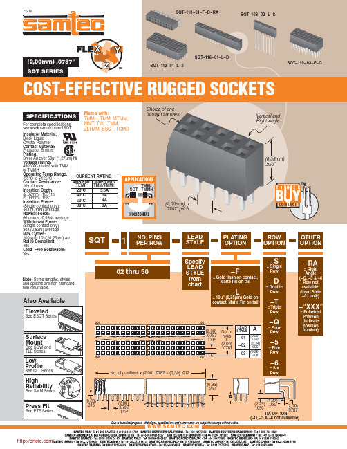
SPECIFICATIONS
For complete specifications see ?SQT
Mates with: TMMH, TMM, MTMM, MMT, TW, LTMM, ZLTMM, ESQT, TCMD
Choice of one through six rows
SQT-106-01-LM-D SQT-112-01-F-D SQT-110-01-L-Q
SQT-110-03-F-D SQT-107-01-L-T SQT-125-01-F-D
(2,29) .050 .090
(2,00) .0787
–RA OPTION
(–Q, –5 & –6 not available)
/
分销商库存信息:
SAMTEC SQT-103-01-F-D SQT-120-01-F-S SQT-110-01-LM-Q SQT-116-01-S-D
TMM/ SQT TMMH
HORIZONTAL
(2,00mm) .0787" pitch
1
NO. PINS PER ROW
LEAD STYLE
(6,35mm) .250"
PLATING OPTION
ROW OPTION
Note: Some lengths, styles and options are non-standard, non-returnable.
20°C
5.5A
(2,62mm) .103" to (5,03mm) .198" Insertion Force: (Single contact only)
40°C
5A
60°C
翔威电子穿心电容规格书
0.1uF
Z
7A 16VDC X7R
LC4030-7008X-100V-223M
额定电压 (DC 直流 与 AC 交流)
材料: X=X7R Y=Y5U/Y5V/Y5P N=NPO ……..
S=SL
注意:
1. 如果需方有自己的尺寸与规格要求,也可告知我们,我们接受定做。 2. 如需定做请尽量提供完整的性能参数及规格尺寸图,以便我们研发生产。 3. 免费样品:5 只(特殊产品除外)单位:毫米(MM)
L
L3
L1
D S
M L2
L
L3
L1
D2 D
D1
订货方式:
XW H C 38 22 - 50 08
L2
X -ห้องสมุดไป่ตู้100VDC - 102M
D2/ M
D1/S
公
电路式:
司
C型
名
Pi 型
称
LC 型
T型
L1
d 08=0.8mm 10=1.0mm
安装方式: H:焊接式 L:螺纹式 G:管状式
电容量 + 精度 100=10PF, K=±10% 101=100PF, M=±20% 102=1000PF,S=+50%,-20% 103=0.01uF, Z=+80%,-20% 104=0.1uF, P=+100%,-0% 105=1uF,……
C
100pF
Z
7A 50VDC SL
LC4030-7008S-50V-101Z
4
M3-0.5 0.8 30.3 7 3 8.3 C
100pF
Z
7A 100VDC SL
LC4030-7008X-50V-103Z
iw3616、3617、3630datasheet中文翻译(绝对真实)

产品特色大幅简化离线式LED驱动器设计●单级功率因数校正(PFC)与精确恒流(CC)输出相结合●输入/输出电容和变压器体积小●一次侧反馈控制,无需光耦电路,简化了电路设计●简化初级侧PWM调光接口●符合IEC61000-3-2标准高效节能和高兼容性●大幅提升效率,可达到85%以上●减少元件数量●总谐波失真<15%且PF>0.95●前沿、后沿和数字调光器●传感器和定时器精确稳定的性能●LED负载恒流精度不低于±5%●支持LED负载热插拔●1%-100%宽范围调光,调光无闪烁先进的保护及安全特性●通过自动重启动提供短路保护●开路故障检测模式●自动热关断重启动无论在PCB板上还是在封装上,都保证高压漏极引脚与其他所有信号引脚之间满足高压爬电要求应用●LED离线固态照明说明G7617 是一款的适用于LED调光控制的离线式两级交流/直流电源控制器,是适用于25W 输出功率的可调光LED 灯具的最优之选。
G7617符合电磁兼容性(EMC) IEC61000-3-2 标准,在120V AC或230V AC输入电压下其功率因数(PF) 可达到0.95 以上。
采用先进的数控技术来检测调光器的类型和相位,为调光器提供动态阻抗的同时可调节LED发光亮度,自动检测调光器类型和相位,从而实现了业内与模拟及数字调光器最广泛的兼容性。
G7617工作于准谐振工作模式,工作效率高,可工作于前沿后沿调光模式,也可工作于R 型、R-C型或R-L型调光控制模式。
G7617 符合热插拔LED 模块的固态照明行业标准Zhaga,同时还集成了调光功能的映射选项(位于白炽灯替代灯的NEMA SSL6 调光曲线内)。
G7617 系列有两个版本:针对120V AC输入应用进行优化的G7617-00 和针对230V AC 应用进行优化的G7617-01。
订购信息应用框图图1典型应用内部框图Vcc VinVcbVT CFGASU BisenseBdrvFdrvFisensePGNDAGND C O R E图2 内部框图引脚功能描述BV SENSE V IN BI SENSE B DRV CFG ASU V CCV CBV TFV SENSEFI SENSEF DRVAGNDPGND 图3. 引脚布局BV SENSE引脚:PFC电感电压反馈点,用于感知Boost电感的磁通状态。
FAIRCHILD FQPF3N60 数据手册
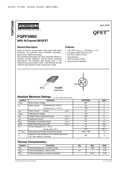
现货库存、技术资料、百科信息、热点资讯,精彩尽在鼎好!©2000 Fairchild Semiconductor International Rev. A, April 2000F Q P F 3N 60FQPF3N60600V N-Channel MOSFETGeneral DescriptionThese N-Channel enhancement mode power field effect transistors are produced using Fairchild’s proprietary,planar stripe, DMOS technology.This advanced technology has been especially tailored to minimize on-state resistance, provide superior switching performance, and withstand high energy pulse in the avalanche and commutation mode. These devices are well suited for high efficiency switch mode power supply.TO-220FG SD©2000 Fairchild Semiconductor International FQPF3N60(Note 4)(Note 4, 5)(Note 4, 5) (Note 4)Rev. A, April 2000Electrical Characteristics T C= 25°C unless otherwise notedNotes:1. Repetitive Rating : Pulse width limited by maximum junction temperature2. L = 92mH, I AS = 2.0A, V DD = 50V, R G = 25 Ω, Starting T J = 25°C3. I SD 3.0A, di/dt 200A/µs, V DD BV DSS, Starting T J = 25°C4. Pulse Test : Pulse width 300µs, Duty cycle 2%5. Essentially independent of operating temperatureSymbol Parameter Test Conditions Min Typ Max UnitsOff CharacteristicsBV DSS Drain-Source Breakdown Voltage V GS = 0 V, I D = 250 µA600----V ∆BV DSS / ∆T J Breakdown Voltage Temperature CoefficientI D = 250 µA, Referenced to 25°C --0.6--V/°C I DSS Zero Gate Voltage Drain Current V DS = 600 V, V GS = 0 V ----10µA V DS = 480 V, T C = 125°C ----100µA I GSSF Gate-Body Leakage Current, Forward V GS = 30 V, V DS = 0 V ----100nA I GSSRGate-Body Leakage Current, ReverseV GS = -30 V, V DS = 0 V-----100nAOn CharacteristicsV GS(th)Gate Threshold Voltage V DS = V GS , I D = 250 µA3.0-- 5.0V R DS(on)Static Drain-Source On-ResistanceV GS = 10 V, I D = 1.0 A -- 2.8 3.6Ωg FSForward TransconductanceV DS = 50 V, I D = 1.0 A--2.2--SDynamic CharacteristicsC iss Input Capacitance V DS = 25 V, V GS = 0 V, f = 1.0 MHz--350450pF C oss Output Capacitance--5065pF C rssReverse Transfer Capacitance--5.57.5pFSwitching Characteristicst d(on)Turn-On Delay Time V DD = 300 V, I D = 3.0 A,R G = 25 Ω--1030ns t r Turn-On Rise Time --3070ns t d(off)Turn-Off Delay Time --2050ns t f Turn-Off Fall Time --3070ns Q g Total Gate Charge V DS = 480 V, I D = 3.0 A,V GS = 10 V--1013nC Q gs Gate-Source Charge -- 2.7--nC Q gdGate-Drain Charge--4.9--nCDrain-Source Diode Characteristics and Maximum RatingsI S Maximum Continuous Drain-Source Diode Forward Current ---- 2.0A I SM Maximum Pulsed Drain-Source Diode Forward Current----8.0A V SD Drain-Source Diode Forward Voltage V GS = 0 V, I S = 2.0 A ---- 1.4V t rr Reverse Recovery Time V GS = 0 V, I S = 3.0 A,dI F / dt = 100 A/µs--210--ns Q rrReverse Recovery Charge-- 1.2--µC©2000 Fairchild Semiconductor International F Q P F 3N 60Rev. A, April 2000©2000 Fairchild Semiconductor InternationalFQPF3N60Rev. A, April 2000©2000 Fairchild Semiconductor International F Q P F 3N 60Rev. A, April 2000©2000 Fairchild Semiconductor International FQPF3N60Rev. A, April 2000©2000 Fairchild Semiconductor InternationalF Q P F 3N 60Rev. A, April 2000TRADEMARKSThe following are registered and unregistered trademarks Fairchild Semiconductor owns or is authorized to use and is not intended to be an exhaustive list of all such trademarks.ACEx™Bottomless™CoolFET™CROSSVOLT™E2CMOS™FACT™FACT Quiet Series™FAST®FASTr™GTO™HiSeC™ISOPLANAR™MICROWIRE™POP™PowerTrench®QFET™QS™Quiet Series™SuperSOT™-3SuperSOT™-6SuperSOT™-8SyncFET™TinyLogic™UHC™VCX™DISCLAIMERFAIRCHILD SEMICONDUCTOR RESERVES THE RIGHT TO MAKE CHANGES WITHOUT FURTHER NOTICE TO ANY PRODUCTS HEREIN TO IMPROVE RELIABILITY, FUNCTION OR DESIGN. FAIRCHILD DOES NOT ASSUME ANY LIABILITY ARISING OUT OF THE APPLICATION OR USE OF ANY PRODUCT OR CIRCUIT DESCRIBED HEREIN; NEITHER DOES IT CONVEY ANY LICENSE UNDER ITS PATENT RIGHTS, NOR THE RIGHTS OF OTHERS.LIFE SUPPORT POLICYFAIRCHILD’S PRODUCTS ARE NOT AUTHORIZED FOR USE AS CRITICAL COMPONENTS IN LIFE SUPPORT DEVICES OR SYSTEMS WITHOUT THE EXPRESS WRITTEN APPROVAL OF FAIRCHILD SEMICONDUCTOR INTERNATIONAL.As used herein:1. Life support devices or systems are devices or systems which, (a) are intended for surgical implant into the body, or (b) support or sustain life, or (c) whose failure to perform when properly used in accordance with instructions for use provided in the labeling, can be reasonably expected to result in significant injury to the user.2. A critical component is any component of a life support device or system whose failure to perform can be reasonably expected to cause the failure of the life support device or system, or to affect its safety or effectiveness.PRODUCT STATUS DEFINITIONSDefinition of TermsDatasheet Identification Product Status DefinitionAdvance Information Formative or InDesign This datasheet contains the design specifications for product development. Specifications may change in any manner without notice.Preliminary First Production This datasheet contains preliminary data, andsupplementary data will be published at a later date.Fairchild Semiconductor reserves the right to makechanges at any time without notice in order to improvedesign.No Identification Needed Full Production This datasheet contains final specifications. FairchildSemiconductor reserves the right to make changes atany time without notice in order to improve design.Obsolete Not In Production This datasheet contains specifications on a productthat has been discontinued by Fairchild semiconductor.The datasheet is printed for reference information only.©2000 Fairchild Semiconductor International Rev. A, January 2000。
- 1、下载文档前请自行甄别文档内容的完整性,平台不提供额外的编辑、内容补充、找答案等附加服务。
- 2、"仅部分预览"的文档,不可在线预览部分如存在完整性等问题,可反馈申请退款(可完整预览的文档不适用该条件!)。
- 3、如文档侵犯您的权益,请联系客服反馈,我们会尽快为您处理(人工客服工作时间:9:00-18:30)。
3UWC-0.6K
♦ Industry Standard 3mm (T1) Package ♦ RoHS Compliant ♦ Water Clear Lens
♦ Available in Shouldered Lead Frame
♦ Up to 1000 mcd Luminous Intensity at 20 mA
♦ Ideal for Back Lighting, Status Indication, and Display ♦
Recommended for Bivar Flexible Light Pipe assemblies
Lens Appearance Viewing Angle
InGaN WHITE
X=.30 Y=.31
3UWC-0.6K
Water Clear
35°
ATTENTION
OBSERVE PRECAUTIONS
FOR HANDLING ELECTROSTATIC SENSITIVE DEVICES
Moisture Sensitivity Levels 1
Bivar 3mm T1 Package Ultra Bright LED is ideal for those applications where intensive ambient lighting exists such as Back Lighting, Signage, and Sunlight Readable applications. Bivar offers water clear LED lens for maximum light output and 35° viewing angle. The Shouldered Lead frame LED has a built in strain relief feature which is ideal for right angle holder and vertical spacer assemblies. Low power consumption and great reliability are suitable for battery-operated applications.
Outline Drawings Notes:
1. All dimensions are in inches [millimeters].
2. Standard tolerance: ±0.010" unless otherwise noted.
3. Tolerance of overall epoxy outline: ±0.020" unless otherwise noted.
4. Epoxy meniscus may extend to 0.060" max.
Absolute Maximum Ratings
T A = 25°C unless otherwise noted
Power Dissipation 70 mW Forward Current ( DC ) 30 mA Peak Forward Current 1 150 mA
Reverse Voltage
5 V
Operating Temperature Range -25 ~ +85°C Storage Temperature Range
-30 ~ +100°C
Lead Soldering Temperature ( 3 mm from the base of the epoxy bulb ) 2 260°C Notes: 1. 10% Duty Cycle, Pulse Width ≤ 0.1 msec. 2. Solder time less than 5 seconds at temperature extreme.
Electrical / Optical Characteristics
T A = 25°C & I F = 20 mA unless otherwise noted
Notes: 1. Tolerance of forward voltage : ±0.05V. 2. Tolerance of dominant wavelength : ±1.0nm.
Part Number
Forward
Voltage (V)1
Recommend Forward Current (mA) Reverse
Current (μA)
Dominant Wavelength (nm)2
Luminous
Intensity Iv (mcd)
Viewing
Angle 2 Ө ½ (deg)
MIN TYP MAX MIN TYP MAX MAX
MIN TYP MAX MIN TYP MAX TYP 3UWC-0.6K / 3.2
3.8
/
20
/
100
/ / / / 1000 / 35
Typical Electrical / Optical Characteristics
T A = 25°C unless otherwise noted
Fig. 2 Directivity Radiation Diagram
Fig. 6 Relative Luminous Intensity vs. Temperature
Fig. 4 Relative Luminous Intensity vs. Forward Current
Normalize @ 20 mA
Fig. 5 Forward Voltage vs. Temperature Fig. 1 Relative Luminous Intensity vs. Wavelength
@ 20mA
Fig. 3 Forward Current vs. Forward Voltage
λ(nm) Iv
W a t t s /s r /m 2
380 460 540 700
620 780 100
300 400
200 0
500 0.2 0.6 0.4
0.5 0.3 0.1 90°
70° 80°
10° 60° 50° 40° 20° 30°
0°
1000 10 1
0.1 100 5.0
4.0 3.0 2.0 1.0
3.0
0.0
1.0
2.0
1 100 10 1000
Vf (V)
If (mA)
If (mA)
Iv
1.2 1.1 0.8 1.0
0.9 80 40
0 -40
80
40 0 -40
T (°C)
Vf (V)
T (°C)
Iv
Recommended Soldering Conditions
Packaging and Labeling Plan
AntiStatic Poly Bag with Desiccant
(500 pcs Max. per Bag)
Preheat Temperature: 100ºC Max. Peak Temperature: 260ºC Max.
Preheat Time: 20 ~ 50 Seconds
Solder Time Above 217ºC: 5 Seconds Max.
Note: Turn off top heater at preheat to prevent the lamp body directly exposed to the heat source.
Recommended Lead Free Wave Soldering Profile
分销商库存信息: BIVAR
3UWC-0.6K。
