马拉松发电机IP44样本
GEP50SP4

GEP50SP4柴油发电机组柴油发电机组 Cat ®代理商独家供应代理商独家供应* 请参阅第4页上的额定值定义。
功率因素为1.0时的额定值。
额定输出发电机组型号 主用* 备用* 220-240V, 50Hz 45.0kVA 50.0kVA 45.0kW50.0kW- ---技术数据发动机制造商和型号: 珀金斯 1104C-44TG2/3 交流发电机型号: LL2014J底架类型: 2型结构钢-(0.8小时) 断路器类型: 3极MCCB频率:Hz 50 60 发动机转速:PRM 1500-燃油箱容量:L (US gal)219(57.9)燃油消耗,主用:L/hr (US gal/hr) 14.3(3.8) - 燃油消耗,备用:L/hr (US gal/hr) 16.7(4.4)- 符合 欧II 排放标准适用于欧洲国家的移动应用场合技术数据需要更多相关信息,请联系您当地的Olympian 代表物理数据 制造商: 珀金斯 型号:1104C-44TG2/3缸数/排列: 4/直列 循环: 4冲程 进气方式: 涡轮增压 冷却方式: 水 控制类型: 机械调速 控制等级: ISO8528 G2 压缩比: 18.2:1 排量:L(cu.in) 4.4(268.5) 缸径/冲程:mm(in) 105.0(4.1)/127.0(5.0)转动惯量:kg m 2(lb.in 2) 1.14(3896)发动机电气系统: -电压(V) / 接地: 12/负极 -电池充电电流(A): 65 干重kg(lb): 463(1021) 湿重kg(lb):485(1069)进气系统 50Hz 60Hz 空气滤清器类型: 滤芯可更换式助燃空气流速:m 3/min(cfm)-备用:4.4(156) - -主用:4.3(153)- 最大进气阻力(助燃空气): kPa (in H 2O) 8.0(32.1)- 散热器冷却气流速:m 3/min (cfm) 97.8(3454) - 冷却气流外部阻力:Pa (in H 2O)125(0.5)-冷却系统 50Hz 60Hz冷却系统容量:L (US gal) 13.0(3.4) -水泵类型: 离心式 冷却水和机油的散热量:kW (Btu/min) -备用: 42.0(2388) - -主用: 38.0(2161) - 发动机表面散热量:kW (Btu/min)-备用: 13.0(739) --主用:9.6(546) - 散热器风扇功率:kW (hp)1.0(1.3)-冷却系统的最高设计运行环境温度为50°C(122°F)。
电动机铭牌上的IP44是什么意思?
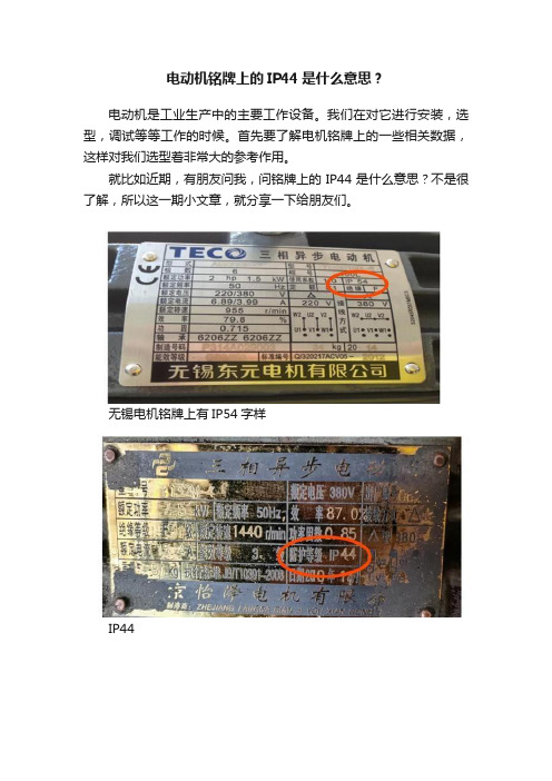
电动机铭牌上的IP44是什么意思?
电动机是工业生产中的主要工作设备。
我们在对它进行安装,选型,调试等等工作的时候。
首先要了解电机铭牌上的一些相关数据,这样对我们选型着非常大的参考作用。
就比如近期,有朋友问我,问铭牌上的IP44是什么意思?不是很了解,所以这一期小文章,就分享一下给朋友们。
无锡电机铭牌上有IP54字样
IP44
IP55
数字各不相同,它们说的什么意思?我们一起来看一看:
IP44在电机铭牌上指的是,防护等级,是英文字母的首字母,缩写。
它代表电机的一种防护工艺级别,等级越高,密封性越好。
当然也越能抗恶劣的环境。
后面的数字,分两部分看:前一个数字指的是防固体物级别。
后一个数字是指防液体级别。
是不是考虑很完善……
其中对于固体物体的防护等级,分为七个级别,分别是从零到六,依次排列。
越靠后,防护等级越高。
液体防护等级,更多一些。
一共是九个等级,大家自己看看,我就不一一列举。
也是同上面一样,等级越高,防护越严格,环境越恶劣。
那么我们再回头看看这个铭牌,是不是很容易理解了。
防护等级固体加液体级别。
电动机型号参数列表之欧阳德创编

Y系列(IP44)交流电机一、概述Y系列电动机是一般用途的全封闭自扇冷式鼠笼型三相异步电动机。
安装尺寸和功率等级符合IEC标准,外壳防护等级为IP44,冷却方法为IC411,连续工作制(S1)。
适用于驱动无特殊要求的机械设备,如机床、泵、风机、压缩机、搅拌机、运输机械、农业机械、食品机械等。
Y系列电动机效率高、节能、堵转转矩高、噪音低、振动小、运行安全可靠。
Y80~315电动机符合Y系列(IP44)三相异步电动机技术条件JB/T96161999。
Y355电动机符合Y系列(IP44)三相异步电动机技术条件JB527491。
Y80~315电动机采用B级绝缘。
Y355电动机采用F级绝缘。
额定电压为380V,额定频率为50Hz。
功率3kW及以下为Y接法;其它功率均为△接法。
电动机运行地点的海拔不超过1000m;环境空气温度随季节变化,但不超过40℃;最低环境空气温度为15℃;最湿月月平均最高相对湿度为90%;同时该月月平均最低温度不高于25℃。
电动机有一个轴伸,按用户需要,可制成双轴伸,第二轴伸亦能传递额定功率,但只能用联轴器传动。
Y250M8306373090.50.8 1.8 6.0 2.07375 1.8391 Y280S83778.274091.00.8 1.8 6.0 2.07378 2.8500 Y280M84593.274091.70.8 1.8 6.0 2.07378 2.8562 Y315S85511474092.00.8 1.6 6.5 2.08287 2.8875 Y315M87515274092.50.8 1.6 6.5 2.08287 2.81008 Y315L189017974093.00.8 1.6 6.5 2.08287 2.81065 Y315L2811021874093.30.8 1.6 6.3 2.08287 2.81195 Y355M2813226474093.80.8 1.3 6.3 2.099 4.51675 Y355M4816031974094.00.8 1.3 6.3 2.099 4.51730 Y355L3818536874294.20.8 1.3 6.3 2.099 4.51840 Y355L4820039874394.30.8 1.3 6.3 2.099 4.51905同步转速 600r/min 10级Y315S104510159091.50.7 1.4 6.0 2.08287 2.8838 Y315M105512359092.00.7 1.4 6.0 2.08287 2.8960 Y315L2107516459092.50.8 1.4 6.0 2.08287 2.81180 Y355M1109019159593.00.8 1.2 6.0 2.096 4.51620 Y355M21011023059593.20.8 1.2 6.0 2.096 4.51775 Y355L11013227559593.50.8 1.2 6.0 2.096 4.51880Y系列异步电动机安装尺寸B3机座带底脚、端盖上无凸缘的电动机安装尺寸机座号极数安装尺寸及公差外形尺寸Overall dimensionA A/2BCDEF G1)H K2)AB AC AD HD L 基本尺寸基本尺寸极限偏差基本尺寸基本尺寸极限偏差基本尺寸极限偏差基本尺寸极限偏差基本尺寸极限偏差基本尺寸极限偏差基本尺寸极限偏差基本尺寸极限偏差位置度公差80M2、412562.5±0.50 10050±1.51940±0.31060.0300.03615.50.108000.510ф1.016517515017529090S2、4、6140701005624508200.209018019516019531590L125340100L1608014063±2.02860±0.3702410012205215180245380112M1909514070112245240190265400132S2、4、6、82161081408938801033132280275210315475132M178515160M254127±0.75 210108±3.042110±0.4301200.0433716015ф1.5330335265385605160L254650180M279139.5241121481442.5180355380285430670180L279710200L31815930513355164920019395420315475775225S4、8356178286149±4.060140±0.5001853225435475345530820225M231155110±0.4301649815 4、6、860140±0.5001853845250M2406203±1.0034916825024ф2.0490515385575930 4、6、86558280S2457228.536819028000.1055058041064010004、6、8752000.05267.5280M2419651800.043581050 4、6、8752000.05267.5315S2508254406216651800.043583152874464557686512404、6、8、10801702200.052711270315M2457651401800.043581310 4、6、8、10801702200.052711340315L2508651401800.043581310 4、6、8、10801702200.0527113401.G =DGE ,GE 的极限偏差对机座号80为(+0.10 0 ),其余为(+0.200 )。
IP44防护等级

防护等级(防水,防尘):IP44关于防护等级标准说明IP(INGRESS PROTECTION)防护等级系统是由IEC(INTERNATIONAL ELECTROTECHNICAL COMMISSION)所起草。
IP防护等级是由两个数字所组成,第一个数字表示电子产品防尘、防止外物侵入的等级;第二个数字表示电子产品防湿气、防水侵入的密闭程度。
数字越大,表示其防护等级越高,两个标示数字所表示的防护等级如表一及表二。
第一个标示特性号码(数字)所指的防护程度第一个标示数字:0 无防护对外界的人或物无特殊之防护IP0-1 防止大于50mm的固体物体侵入,防止人体(如手掌)因意外而接触到电子产品内部之零件。
防止较大尺寸(直径大于50mm)的外物侵入IP1-2 防止大于12mm的固体物体侵入,防止人的手指接触到电子产品内部之零件。
防止中等尺寸(直径大于12mm,长度大于80mm)的外物侵入IP2-3 防止大于2.5mm的固体物体侵入,防止直径或厚度大于2.5mm之工具、电线或类似的细小的外物侵入而接触到电子产品的内部零件IP3-4 防止大于1.0mm的固体物体侵入,防止直径或厚度大于1.0mm之工具、电线或类似的细小的外物侵入而接触到电子产品的内部零件IP4-5 防尘,完全防止外物侵入。
虽不能完全防止灰尘侵入,但侵入的灰尘的量并不会影响电子产品的正常操作IP5-6 尘密完全防止外物侵入,且可完全防止灰尘侵入IP6- 第二个标示特性号码(数字)所指的防护程度第二个标示数字:0 无防护对外界的人或物无特殊之防护IP-01 防止滴水侵入,垂直滴下的水滴(如凝结水)对电子产品不会造成有害影响IP-12 倾斜15°时仍可防止滴水侵入,当电子产品由垂直倾斜至15°时,滴水对电子产品不会造成有害影响IP-23 防止喷洒的水侵入,防雨或防上与垂直的夹角小于60°之方向所喷洒的水进入电子产品造成损坏IP-34 防止飞溅的水侵入,防止各方向飞溅而来的水进入电子产品造成损坏IP-45 防止喷射的水侵入,防止来自各方向由喷嘴喷射出的水进入电子产品造成损坏IP-56 防止大浪的侵入,装设于甲板上的电子产品,防止因大浪的侵袭而浸水造成损坏IP-67 防止浸水时的水侵入,电子产品浸在水中一定的时间或水压在一定的标准以下能确保不因进水而造成损坏IP-78 防止沉没时的水侵入,电子产品无限期的沉没早指定水压的状况下,能确保不因进水而造成损坏IP-8。
电动机型号参数列表之欧阳治创编
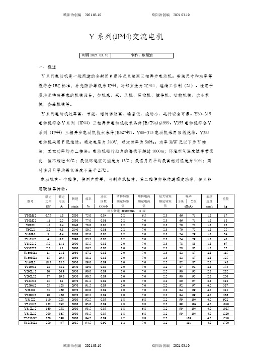
Y系列(IP44)交流电机一、概述Y系列电动机是一般用途的全封闭自扇冷式鼠笼型三相异步电动机。
安装尺寸和功率等级符合IEC标准,外壳防护等级为IP44,冷却方法为IC411,连续工作制(S1)。
适用于驱动无特殊要求的机械设备,如机床、泵、风机、压缩机、搅拌机、运输机械、农业机械、食品机械等。
Y系列电动机效率高、节能、堵转转矩高、噪音低、振动小、运行安全可靠。
Y80~315电动机符合Y系列(IP44)三相异步电动机技术条件JB/T96161999。
Y355电动机符合Y 系列(IP44)三相异步电动机技术条件JB527491。
Y80~315电动机采用B级绝缘。
Y355电动机采用F级绝缘。
额定电压为380V,额定频率为50Hz。
功率3kW及以下为Y接法;其它功率均为△接法。
电动机运行地点的海拔不超过1000m;环境空气温度随季节变化,但不超过40℃;最低环境空气温度为15℃;最湿月月平均最高相对湿度为90%;同时该月月平均最低温度不高于25℃。
电动机有一个轴伸,按用户需要,可制成双轴伸,第二轴伸亦能传递额定功率,但只能用联轴器传动。
Y200L81534.173088.00.8 1.8 6.0 2.07072 1.8228 Y225S818.541.373089.50.8 1.7 6.0 2.07075 1.8265 Y225M82247.673090.00.8 1.8 6.0 2.07075 1.8296 Y250M8306373090.50.8 1.8 6.0 2.07375 1.8391 Y280S83778.274091.00.8 1.8 6.0 2.07378 2.8500 Y280M84593.274091.70.8 1.8 6.0 2.07378 2.8562 Y315S85511474092.00.8 1.6 6.5 2.08287 2.8875 Y315M87515274092.50.8 1.6 6.5 2.08287 2.81008 Y315L189017974093.00.8 1.6 6.5 2.08287 2.81065 Y315L2811021874093.30.8 1.6 6.3 2.08287 2.81195 Y355M2813226474093.80.8 1.3 6.3 2.099 4.51675 Y355M4816031974094.00.8 1.3 6.3 2.099 4.51730 Y355L3818536874294.20.8 1.3 6.3 2.099 4.51840 Y355L4820039874394.30.8 1.3 6.3 2.099 4.51905同步转速 600r/min 10级Y315S104510159091.50.7 1.4 6.0 2.08287 2.8838 Y315M105512359092.00.7 1.4 6.0 2.08287 2.8960 Y315L2107516459092.50.8 1.4 6.0 2.08287 2.81180 Y355M1109019159593.00.8 1.2 6.0 2.096 4.51620 Y355M21011023059593.20.8 1.2 6.0 2.096 4.51775 Y355L11013227559593.50.8 1.2 6.0 2.096 4.51880Y系列异步电动机安装尺寸B3机座带底脚、端盖上无凸缘的电动机安装尺寸机座号极数安装尺寸及公差外形尺寸Overall dimensionA A/2BCDEF G1)H K2)AB AC AD HD L 基本尺寸基本尺寸极限偏差基本尺寸基本尺寸极限偏差基本尺寸极限偏差基本尺寸极限偏差基本尺寸极限偏差基本尺寸极限偏差基本尺寸极限偏差基本尺寸极限偏差位置度公差80M2、412562.5±0.50 10050±1.51940±0.31060.0300.03615.50.108000.510ф1.016517515017529090S2、4、6140701005624508200.209018019516019531590L125340100L1608014063±2.02860±0.3702410012205215180245380112M1909514070112245240190265400132S2、4、6、82161081408938801033132280275210315475132M178515160M254127±0.75 210108±3.042110±0.4301200.0433716015ф1.5330335265385605160L254650180M279139.5241121481442.5180355380285430670180L279710200L31815930513355164920019395420315475775225S4、8356178286149±4.060140±0.5001853225435475345530820225M231155110±0.4301649815 4、6、860140±0.5001853845250M2406203±1.0034916825024ф2.0490515385575930 4、6、86558280S2457228.536819028000.1055058041064010004、6、8752000.05267.5280M2419651800.043581050 4、6、8752000.05267.5315S2508254406216651800.043583152874464557686512404、6、8、10801702200.052711270315M2457651401800.043581310 4、6、8、10801702200.052711340315L2508651401800.0435813104、6、8、10 80 17022 00.052 71 13401.G =DGE ,GE 的极限偏差对机座号80为(+0.10 0 ),其余为(+0.200 )。
Y系列(IP44)三相异步电动机(西玛电机有限公司)
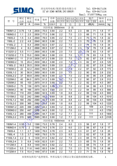
西安西玛电机(集团)股份有限公司
Tel:029-86171136
XI'AN SIMO MOTOR,INC(GROUP)
Fax:029-86171116
Email:571057738@
Y90S-6 Y90L-6 Y100L-6 Y112M-6 Y132S-6 Y132M1-6 Y132M2-6 Y160M-6 Y160L-6 Y180M-6 Y200L1-6 Y200L2-6 Y225M-6 Y250M-6 Y280S-6 Y280M-6 Y315S-6 Y315M-6
西 安 西玛 电 机(集 团)股 份 有限 公 司
6.8
2.2
93.0 0.89 1.8
6.8
2.2
93.5 0.89 1.8
6.8
2.2
93.5 0.89 1.8
6.8
2.2
94.2 0.89 1.2
6.9
2.2
94.5 0.90 1.2
7.0
2.2
94.7 0.90 1.2
7.1
2.2
95.0 0.90 1.2
7.1
2.2
同步转速 1500r/min 4 级
21 24 35 45 66 75 85 116 128 182 228 246 294 395 505 566 850 965
本资料仅供用户选型使用,外形安装尺寸图以订货后提供的图纸为准。
2
型号
Y315L1-6 Y315L2-6 Y355M1-6 Y355M2-6 Y355M4-6 Y355L1-6 Y355L3-6
750技术参数

e
Voltage Rating Code C D E F Voltage 400V AC/540V DC 480V AC/650V DC 600V AC 690V AC (not UL listed)
4
洛克威爾自動化出版物 750-TD001E-ZC-P - 2011 年 11 月
PowerFlex 750 系列交流變頻器
Cabinet Options (21G)
a
Drive Code 20F 20G 21G Type PowerFlex 753 PowerFlex 755 PowerFlex 755 Drive with Options 2P1 2.1 3.5 5.0 8.7 11.5 15.4 22 30 37 43 60 72 85 104 140 170 205 260 302 367 456 460 540 567 650 750 770 910 1040 1090 1175 1465 1480 Code Amps
d
Enclosure Code B Description IP20, NEMA/UL Type 1, 2500 MCC Style Cabinet, 600 mm (23.6 in.) Deep Flange (NEMA/UL Type 4X/12 back) IP54, NEMA/UL Type 12 IP20, NEMA/UL Type 1, 2500 MCC Style Cabinet, 800 mm (31.5 in.) Deep IP20/IP00, NEMA/UL Type Open IP20, NEMA/UL Type 1, 2500 MCC Style Cabinet & Options w/MCC Power Bus, 800 mm (31.5 in.) Deep, St NEMA/UL Type 1, 2500 MCC Style Cabinet & Options w/MCC Power Bus, 800 mm (31.5 in.) Deep, CenterLine 2100 Gray (ASA49)
电机厂产品.doc
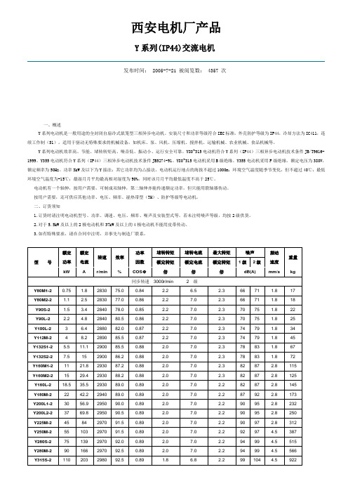
西安电机厂产品Y系列(IP44)交流电机发布时间: 2005-7-21 被阅览数: 4357 次一、概述Y系列电动机是一般用途的全封闭自扇冷式鼠笼型三相异步电动机。
安装尺寸和功率等级符合IEC标准,外壳防护等级为IP44,冷却方法为IC411,连续工作制(S1)。
适用于驱动无特殊要求的机械设备,如机床、泵、风机、压缩机、搅拌机、运输机械、农业机械、食品机械等。
Y系列电动机效率高、节能、堵转转矩高、噪音低、振动小、运行安全可靠。
Y80~315电动机符合Y系列(IP44)三相异步电动机技术条件JB/T9616-1999。
Y355电动机符合Y系列(IP44)三相异步电动机技术条件JB5274-91。
Y80~315电动机采用B级绝缘。
Y355电动机采用F级绝缘。
额定电压为380V,额定频率为50Hz。
功率3kW及以下为Y接法;其它功率均为△接法。
电动机运行地点的海拔不超过1000m;环境空气温度随季节变化,但不超过40℃;最低环境空气温度为-15℃;最湿月月平均最高相对湿度为90%;同时该月月平均最低温度不高于25℃。
电动机有一个轴伸,按用户需要,可制成双轴伸,第二轴伸亦能传递额定功率,但只能用联轴器传动。
按用户需要,还可供应其他功率、电压、频率、湿热带型(TH)、防护等级等电动机。
二、订货须知1.订货时请注明电动机型号、功率、调速、电压、频率、噪声及安装型式等。
若未注明噪声等级,均按2级供货。
2.对于5.5kW及以上的2极电动机和37kW及以上的4极电动机不能用皮带传动。
3.如有特殊要求,请在合同中注明,并事先与制造厂联系。
Y/YR系列高压三相异步电动机发布时间: 2005-7-19 被阅览数: 2749 次Y系列6kV高压三相异步电动机一、概述Y系列6kV高压三相异步电动机为笼型转子异步电动机。
该电动机的防护等级为IP23,冷却方法为IC01。
本系列电动机具有高效、节能、噪声低、振动小、重量轻、性能可靠、安装维修方便等优点。
电动机型号参数列表之欧阳体创编
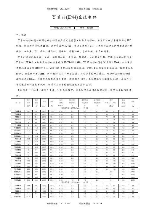
Y系列(IP44)交流电机一、概述Y系列电动机是一般用途的全封闭自扇冷式鼠笼型三相异步电动机。
安装尺寸和功率等级符合IEC 标准,外壳防护等级为IP44,冷却方法为IC411,连续工作制(S1)。
适用于驱动无特殊要求的机械设备,如机床、泵、风机、压缩机、搅拌机、运输机械、农业机械、食品机械等。
Y系列电动机效率高、节能、堵转转矩高、噪音低、振动小、运行安全可靠。
Y80~315电动机符合Y系列(IP44)三相异步电动机技术条件JB/T9616-1999。
Y355电动机符合Y系列(IP44)三相异步电动机技术条件JB5274-91。
Y80~315电动机采用B级绝缘。
Y355电动机采用F级绝缘。
额定电压为380V,额定频率为50Hz。
功率3kW及以下为Y接法;其它功率均为△接法。
电动机运行地点的海拔不超过1000m;环境空气温度随季节变化,但不超过40℃;最低环境空气温度为-15℃;最湿月月平均最高相对湿度为90%;同时该月月平均最低温度不高于25℃。
电动机有一个轴伸,按用户需要,可制成双轴伸,第二轴伸亦能传递额定功率,但只能用联轴器传动。
Y355L3-818536874294.20.8 1.3 6.3 2.099 4.51840 Y355L4-820039874394.30.8 1.3 6.3 2.099 4.51905同步转速 600r/min 10级Y315S-104510159091.50.7 1.4 6.0 2.08287 2.8838 Y315M-105512359092.00.7 1.4 6.0 2.08287 2.8960 Y315L2-107516459092.50.8 1.4 6.0 2.08287 2.81180 Y355M1-109019159593.00.8 1.2 6.0 2.096 4.51620 Y355M2-1011023059593.20.8 1.2 6.0 2.096 4.51775 Y355L1-1013227559593.50.8 1.2 6.0 2.096 4.51880Y系列异步电动机安装尺寸B3机座带底脚、端盖上无凸缘的电动机安装尺寸机座号极数安装尺寸及公差外形尺寸Overall dimensionA A/2BCDEF G1)H K2)AB AC AD HD L 基本尺寸基本尺寸极限偏差基本尺寸基本尺寸极限偏差基本尺寸极限偏差基本尺寸极限偏差基本尺寸极限偏差基本尺寸极限偏差基本尺寸极限偏差基本尺寸极限偏差位置度公差80M 2、4 125 62.5±0.50 100 50±1.519 40±0.3106-0.030-0.03615.5-0.10800-0.510ф1.0165 175 150 175 29090S2、4、6 140 7010056 24 50820-0.2090 180 195 160 19531590L 125 340 100L 160 80 140 63±2.0 28 60±0.3702410012205 215 180 245 380112M 190 95 140 70 112 245 240 190 265 400 132S2、4、6、8 216 10814089 38 80 10 33 132 280 275 210 315475132M 178 515160M254 127±0.75 210108±3.042110 ±0.430120-0.04337 16015ф1.5330 335 265 385605160L 254 650180M279 139.5 241121 48 14 42.5 180 355 380 285 430670180L 279 710200L 318 159 305 133 55 16 49 20019 395 420 315 475 775225S 4、8356 178 286149±4.060 140 ±0.500 18 53225 435 475 345 530820225M231155 110 ±0.430 16 49 815 4、6、860140±0.5001853845250M2406 203±1.00349 168 25024ф2.0490 515 385 575 930 4、6、865 58280S2457 228.5 368190 2800-0.10550 580 410 64010004、6、8 75 20 0-0.052 67.5280M241965 18 0-0.043 581050 4、6、8 75 20 0-0.052 67.5315S2508 254 40621665 18 0-0.043 58315 28 744 645 576 86512404、6、8、10 80 170 22 0-0.052 71 1270315M245765 140 18 0-0.043 58 1310 4、6、8、10 80 170 22 0-0.052 71 1340315L250865 140 18 0-0.043 58 1310 4、6、8、10 80 170 22 0-0.052 71 13401.G=D-GE,GE的极限偏差对机座号80为(+0.10),其余为(+0.20)。
马拉松发电机Magnapower说明书

Power Generation for the 21st CenturyInstallation,Operation, andMaintenance ManualISO 9001: 2000 CertifiedTable of ContentsSection Page 1Safety . . . . . . . . . . . . . . . . . . . . . . . . . . . . . . . . . . . . . . . . . . . . . . . . . . . . . . . .1 2General Information . . . . . . . . . . . . . . . . . . . . . . . . . . . . . . . . . . . . . . . . . . . .2-3 3Installation . . . . . . . . . . . . . . . . . . . . . . . . . . . . . . . . . . . . . . . . . . . . . . . . . . .4-9 4Operation . . . . . . . . . . . . . . . . . . . . . . . . . . . . . . . . . . . . . . . . . . . . . . . . . .10-11 5Maintenance . . . . . . . . . . . . . . . . . . . . . . . . . . . . . . . . . . . . . . . . . . . . . . .12-15 6Service . . . . . . . . . . . . . . . . . . . . . . . . . . . . . . . . . . . . . . . . . . . . . . . . . . . .16-34 7Troubleshooting . . . . . . . . . . . . . . . . . . . . . . . . . . . . . . . . . . . . . . . . . . . . .35-38 8Generator Testing . . . . . . . . . . . . . . . . . . . . . . . . . . . . . . . . . . . . . . . . . . .39-42 9Special T ools . . . . . . . . . . . . . . . . . . . . . . . . . . . . . . . . . . . . . . . . . . . . . . .43-44 10Preparation for Shipment or Storage . . . . . . . . . . . . . . . . . . . . . . . . . . . . . . .45 11Specification and Data . . . . . . . . . . . . . . . . . . . . . . . . . . . . . . . . . . . . . . .46-47 Generator Formulas . . . . . . . . . . . . . . . . . . . . . . . . . . . . . . . . . . . . . . . . . . . .48Warnings & Cautions . . . . . . . . . . . . . . . . . . . . . . . . . . . . . . .Inside Back CoverSection 1SafetyPLEASE REMEMBER SAFETY FIRST.If you are not sure of the instructions or procedures, seek qualified help before continuing.This service manual emphasizes the safety pre-cautions necessary during the installation, operation and maintenance of the MAGNAPOWER®generator.Each section has caution and warning messages. These messages are for your safety and the safety of the equipment involved.If any of the cautions or warnings are not readily understood, seek clarification from qualified personnel before proceeding.Before any service work is done, disconnect all power sources and, where appropriate, lock out all controls to prevent an unexpected start-up of the generator set.Proper grounding in compliance with local and national electrical codes must be provided.These safety precautions are necessary to prevent potential serious personal injury, or even death.The hazards associated with lifting or moving the MAGNAPOWER®generator are pointed out in the installation and service sections;incorrect lifting or moving can result in personal injury or property damage.Whenever the generator is running, always assume and proceed as if voltage is present.Residual voltage is present at the generator leads and at the regulator panel connections, even with the regulator fuse removed.Caution must be observed.Otherwise, serious personal injury or death can result.Whenever solvents, cleaners, or flammable liquids are present, adequate ventilation must be available to avoid fire, explosion, and health hazards.Always avoid breathing vapors and use suitable personal protective equipment to prevent personal injuries (such as eyes, face, and hand protection).This manual is not intended to be a substitute for properly trained personnel.Repairs should only be attempted by qualified, trained people.The cautions and warnings point out known conditions that are potentially dangerous.Each installation will create its own set of circumstances.No manual can cover every possible situation.When in doubt, ask.Don’t be embarrassed to ask “dumb questions.”Remember, dumb questions are much easier to handle than dumb mistakes.A Few Words About Safety1General Information Section 2GeneralAll single and two bearing units are manufactured with cast iron end brackets and adapters and fabricated steel frames.Flexible drive discs and SAE adapters are machined to SAE standards.Prelubricated, regreasable, shielded ball bearings are used on MAGNAPOWER®generators.Standard units are fully guarded.Dripproof shields are available as an option.Conduit BoxAssembly is optimized for customer flexibility.Various access panels and a low voltage control section are provided.The external load leads can enter the conduit box from the top, bottom, or side.Furthermore, the conduit box is designed to accept various auxiliary devices (potential and current transformers, etc.) while maintaining a compact generator outline.All models are equipped with an end-mounted conduit box as standard.Optional conduit box designs are available to meet customer requirements.MAGNAPOWER®Uni-rotor Construction Laminations are 4-pole, one piece laminations which are shrunk fit and keyed to the shaft.No dovetails, cross bolts or other pole to shaft connecting devices are used.An amortisseur winding is standard.The cast unidirectional aluminum alloy ventilating fan provides even air distribution to maximize cooling and generator efficiency.Adapters and Drive DiscsAll single bearing units are available with several adapter and drive disc arrangements.These can be shipped to order or can be changed in the field with standard shop tools.When changing flexible drive discs, spacers are used between the discs and the cast iron hub to maintain SAE standard dimensions.Electrical DesignGeneralAll standard products have 2/3 pitch main windings to eliminate the third harmonic.This serves to lower operating temperatures, give lower harmonic content and better wave form, and extend the overall life of the generator.The phase sequence is ABC when rotated counterclockwise viewing exciter end.Temperature RiseAll ratings and frame sizes are based on NEMA Class F and Class H temperature rises on both the rotor and stator windings.Ratings for British, German, French, IEC, and all popular marine agencies are available. Standby GeneratorSynchronous generators used on emergency backup power can have temperature rises up to 25°C above those for continuous operation (NEMA MG1-22.40 and MG 1-22.84).Premium Insulation SystemAll MAGNAPOWER®generators are built with Class F or better insulation materials.All standard generators are suitable for continuous duty at Class F temperature rise and will give equivalent or better winding life expectancy to generators supplied with Class A or B insulation systems operated within their temperature limits.MAGNAPOWER®generators are manufactured with an epoxy Vacuum Pressure Impregnated (VPI) insulation system and form-wound coils, which make the standard winding fungus-resistant and suitable for high humidity and abrasive environments.The MAGNAPOWER®rotor is wet-wound with thermo-setting epoxy applied between each layer, plus a final coating of epoxy for moisture and abrasion resistance. Power FactorAll standard generators are designed for operation at rated kVA at 0.8 lagging power factor but can be operated at rated kVA over the 0.8 to 1.0 power factor range.DVR®2000E Voltage RegulatorThe standard voltage regulator is a fully encapsulated, static type with a solid state build up circuit.Standard features include 3 phase RMS sensing, paralleling, adjustable underfrequency protection, and overexcita-tion protection.The regulator meets EMI suppression to Mil Std-461C, part 9.An optional feature is adjustable armature current limiting.See the regulator manual for more information.Mechanical Design 2It is extremely important to properly identify the machine when requesting parts or service.Always have available the generator model number and serial number when requesting information from the factory.We cannot help you without this information.It is also beneficial to know the mounting arrangement code.An Example for MAGNAPOWER ®GeneratorsExample:1020FSL 5000Frame Number F – Form Wound S – 1 Bearing D – 2 Bearings L – Up to 480 volts S – 600 voltsM – 1000-6600 volts H – 6900-13,800 volts Style T ypeSection 2General InformationHow to Read a Model Number3InstallationSection 3Receiving Your MAGNAPOWER ®GeneratorUpon receipt of the generator, it is recommended that it be carefully examined for possible damage incurred in shipment.The generator was given to the freight company in good condition, and they are responsible for the product from our dock to yours.Any damage should be noted on the freight bill before accepting the shipment.Claims for damage must be promptly filed with the freight company.Unpacking and HandlingRead all instruction cards carefully.When lifting, attach an overhead crane to the lifting lugs on the generator frame.Apply lifting forces in a vertical direction.The lifting lugs on the generator areDo not lift complete generator set by means of lifting lugs on generator.Personal injury or equipment damage may result.StorageIn the event that the generator is not to be installed on the prime mover immediately, it is recommended that itbe stored in a clean, dry area which is not subject to rapid changes in temperature and humidity.See Section 11 for more information.Preparation for UseAlthough the generator is carefully inspected and tested in operation before it leaves the factory, it is recommended that the unit be thoroughly inspected.The insulation on the wire should be inspected and all bolts should be checked for tightness.Remove all shipping tapes, bags, blocks, and skidswhich are used to prevent vibration and rotor move-ment during shipment.Dry, low-pressure compressed air of approximately 30 psi (206 KPA) can be used to blow out the interior of the generator.In the case of two bearing machines, it is possible to turn the rotor by hand to make sure that it rotates smoothly without binding.If the machine has been in storage for a year or longer,it is recommended that it be lubricated according to thelubrication instructions and chart found in Section 5.If the machine has been exposed to damp, humid conditions, the insulation resistance should be checked.Refer to Section 8.Generator Mounting – Single BearingSingle bearing generators are provided with an SAE flywheel adapter and flexible drive discs.Very close tolerances are maintained in the manufacture of the generator so that the alignment procedure is extremely simple.A coupling hub of nodular iron is shrunk onto the shaft and special steel drive discs are bolted to the hub.Holes are provided in the periphery of the coupling disc which correspond to tapped holes in the flywheel.The outside diameter of the discs fits in a rabbet in the flywheel so that concentricity is assured in all cases.Do not apply any force to generator fanfor lifting or rotating generator rotor.Disregarding these instructions may cause personal injury or equipment damage.Grade 8 capscrews and heavy serieslockwashers or grade 8 placebolts and hardened washers are recommended to mount the drive discs to the flywheel.The SAE adapter and the flywheel housing are designed to match each other with no further alignment necessary.Shims may be necessary under the feet of the generator to insure a solid mounting.See Section 6for more information.Generator Mounting – Two BearingT wo bearing generators are provided with a shaft extension and keyway.For direct-coupled units, the assembler furnishes a flexible coupling which is installed between the driver and the generator shaft.Important:Aligning the two machines as accurately as possible will reduce the vibration, increase bearing life, and insure minimum coupling wear.It may be necessary to shim the generator feet for proper support and alignment.Consult the coupling manufacturer’s instructions for alignment specifications and procedures.4Section 3InstallationEnvironmental ConsiderationsDirt, moisture, heat, and vibration are enemies of electrical equipment.Excessive exposure to the elements will shorten the life of the generator. The ambient temperature should not exceed the value shown on the generator nameplate.The MAGNAPOWER®is built in a NEMA open type enclosure.Generators for outdoor application should be protected from the elements by housings with proper openings for ventilation.This protection should be designed to prevent the direct contact of wind driven rain, snow, or dust with the generator.In moist or humid areas, such as the tropics and marine service, additional protection is recommended.Although the standard windings are humidity and moisture resistant, special insulations and accessories such as space heaters can increase generator life significantly.In extremely dirty and dusty environments, a means of providing filtered cooling air to the generator is recom-mended.Refer to Marathon Electric for more information. Electrical ConnectionsThe generator conduit box construction allows conduit to enter the top, bottom, or either side of the box.A hole-saw or any suitable tool can be used to provide for the conduit entrance.Protect the interior of the generator from shavings when drilling or sawing.An approved connector must be used in conjunction with the conduit. T o minimize the transmission of vibration, it is essential that flexible conduit be used for all electrical entrance to the generator.Refer to the connection diagram supplied with the generator and/or the proper diagrams shown in this section.Install all intercomponent and external wiring in accordance with the regulations of the national and local electrical codes.Clean all contact surfaces to assure good electrical bonding with the generator lugs or bus e heavy duty terminal lugs or good quality clamps for making all connections.Insulate all connections in accordance with national and local regulations.Be sure the generator frame is grounded to all the other components of the system with a ground wire in accordance with national and local regulations. Generator Lead ConnectionsThe electrical connections in the conduit box should be made in accordance with the appropriate “connection diagram.”Use the diagram appropriate for the number of leads and voltage range required.Refer to the drawings supplied with the generator and to drawings in this section. The final voltage setting is established within the selected range by an adjustment of the voltage regulator.Some generators have multiple,identi-Connect all identically marked cables together when making connections.5Installation Section 36 Lead Wye6 Lead Delta6Section 3Installation Typical System Diagram7Installation Section 3MAGNAPOWER®generators come standard with amortisseur windings.This exclusive uni-rotor construction makes all MAGNAPOWER®generators suitable for paralleling operations when the proper control equipment is added.Paralleling with other generator sets and/or with the utility power grid offers a number of advantages.Multiple unit installations increase power capacity;they can be added or removed from the line depending on the load requirements;they can be better maintained and repaired (since single source breakdown would mean total loss of power), and they often provide more reliable, efficient, and economical operation. Successful parallel operation means that the generators deliver power to the external system without delivering power to each other, or accepting power from the load bus or power grid.Additional equipmentis necessary to insure safe and successful operation. Prime MoverThe prime mover provides the speed and torque which will be necessary to keep the machines in synchro-nized operation.The governor will directly control the watt or kW load and frequency of the unit.The prime mover speed is controlled by a governor.The governor must have special paralleling provisions to permit parallel operation with the other machines.Voltage RegulatorThe voltage regulator controls the generator output voltage and the reactive power supplied by the generator.When two or more AC generators operate in parallel, the voltage regulator must have paralleling provisions (either internally or external to the regulator) to allow the voltage regulator to control the reactive or VAR load while it is in parallel operation.A separate paralleling current transformer is required to sense the reactive current and signal the voltage regulator.This additional paralleling circuitry is absolutely necessary to control the reactive current flowing between the generator sets.SwitchgearThere are additional relays and breaker controls which are necessary to insure safe, trouble free operation of paralleled units.Reverse power relays monitor the direction of power flow to insure that the generator is delivering the power, not accepting it.These power relays control breakers, which are a means of connecting and disconnecting the generator from the load.The total system can include over-voltage, over-current protection, under frequency protection, power factor correction provision and various associated control equipment from manual switchgear to microprocessors.The amount of control gear and level of sophistication will be determined by the needs and requirements of the particular application.Paralleling BasicsThe following points are basic criteria which must be met before two units can be paralleled.THIS IS NOT MEANT TO BE SPECIFIC INSTRUCTIONS FOR PARALLELING OPERATION.1.Additional paralleling circuitryA.Voltage regulator-paralleling provisionsB.Paralleling current transformer(s)C.Paralleling provisions on governor controlsD.Switchgear2.The voltage and frequency must be the same for allsets with voltages in phase.3.The voltage regulation characteristics of the individualgenerators should be similar.4.The generators must have the same phase rotation.5.The driving engines should have the same speedregulation characteristics and the governors should be adjusted to give the same speed regulation.Before operating generator sets in parallel, each set should be checked by starting, operating, and adjusting the sets as individual units before attempting paralleling.Reactive Load ControlWhen two identical generators are operating together in parallel and an unbalance occurs in field excitation, circulating currents begin to flow between the genera-tors.This current will appear as a lagging power factor or inductive load to the highly excited generator, and as a leading power factor or capacitive load to the generatorParalleling Operations8Section 3Installationwith the lower field current.This is known as the reac-tive circulating current, and there are two methods of controlling it in parallel operation:1.Reactive droop compensation (formerly known asparallel droop compensation) – the bus voltage droops, or decreases, as the reactive lagging power factor load is increased.2.Reactive differential compensation (formerly knownas cross current compensation) – the reactive differential compensation circuit allows parallel generators to share reactive loads with no decrease or droop in generator voltage.The circuit must meet the following criteria:A.All paralleling current transformers for all thegenerators being paralleled must be included inthe secondary interconnection loop.B.When different size generators are paralleled,all paralleling current transformers must havethe same or proportional ratios that giveapproximately the same secondary current.C.Voltage regulator paralleling circuitry must bethe same.D.Current transformer secondaries and thegenerator lines must be isolated electrically.Because of the preceding criteria, reactivedifferential compensation cannot be used whenparalleling with the utility power grid.There is nolimit, however, in the number of generators thatcan be included in this type of circuit.E.It is also desirable to have an auxiliary contacton the main generator breaker to short theparallel CT secondary when that breaker isopen (not connected to the load bus). Paralleling CircuitryBecause of the number of variables involved in paralleling generator sets, every installation will have its own circuitry and methods or procedure of bringing paralleled units on line.There are numerous ways of connecting paralleled units and an almost unlimited variety of applications and associated equipment.When parallel operation is desired, it is important that the control manufacturer, the generator manufacturer, and the systems engineer work together to insure the proper selection of all components.Please refer to Marathon Electric for application assistance. Thyristor or SCR LoadingSolid state electronic control devices which utilize thyristors or SCR firing circuits (such as variable frequency induction motor controls, precision motor speed controls, no-break powered battery chargers, etc.) can introduce high frequency harmonics which adversely affect or destroy the normal waveform of the generator.This creates additional heat in the generator stator and rotor and can cause overheating. These devices can and do present problems to non-utility power generating equipment or any limited power bus system.The problems which can occur are not limited to the generator itself, but can effect the solid state control device, the equipment it controls, other associated loads, monitoring devices, or a number of combinations over the entire system. MAGNAPOWER®generators can supply power to thyristor or SCR loads when properly applied.When SCR loads are more than 25% of the total load, select the generator based on the 80°C R/R rating.The standard voltage regulator is PMG powered and senses 3 phase RMS voltages for maximum stability against severely distorted wave forms.SCR type applications such as cranes, shovels, etc., require special consideration of the generator insulation system due to greater dielectric stress and severe environmental conditions.It is important that the control manufacturer, the generator manufacturer, and the systems engineer work together to insure the proper selection of all components.Please refer to Marathon Electric for application assistance.OperationSection 4Pre-Start InspectionBefore operating the generator for the first time, the fol-lowing checks are recommended:1. A visual inspection should be made to check for anyloose parts, connections, or foreign materials.Refer to section 8.2.Check for clearance in the generator and exciter airgap.Be sure the generator set turns over freely.Bar the generator over by hand at least 2 revolutions to be sure there is no interference.Do not apply any force to generator fanDisregarding these instructions may cause personal injury or equip-ment damage.3.Check all wiring against the proper connectiondiagrams and make sure all connections are properly insulated.Support and tie leads to keepthem from being damaged by rotating parts or by chafing on sharp corners.4.Be sure the equipment is properly grounded.5.Inspect for any remaining packing materials andremove any loose debris, building materials, rags, etc., that could be drawn into the generator.6.Check fasteners for tightness.7.Check to be sure no tools or other hardware havebeen left inside or near the machine.8.Install and check to be sure all covers and guardsare in place and secure.Residual voltage is present at thetions,even with the regulator fuse removed.Caution must be observed or serious personal injury or death can result.Consult qualified personnel with any questions.Starting Up the GeneratorThe following procedure should be followed for starting up the generator for the first time:1.The generator output must be disconnected fromthe load.Be certain that the main circuit breaker is open.2.Disable the voltage regulator by removing the fuse.Do not overspeed the generator.Excessive centrifugal forces could damage the rotating fields.Be prepared for an emergency shut-down.3.Follow the manufacturer’s instructions and start theprime mover.Check the speed and adjust to the rpm shown on the generator nameplate.4.Replace the regulator fuse and adjust the voltageto the required value (figure 4-2).Check all line to line and line to neutral voltages to be sure they are correct and balanced.If the voltages are not correct, shut down immediately and recheck all connections.See section 3.5.Close the main circuit breaker and apply the load.6.Monitor the generator output current to verify it is ator below nameplate amps.7.Adjust engine speed at full load to 1800 rpm for60 Hz, 1500 rpm for 50 Hz (refer to prime mover/governor instruction manuals).8.Before stopping the engine, remove the load bytripping the main circuit breaker.Section 4OperationVoltage AdjustmentsThe generator output voltage is controlled by the voltage regulator.There is a cover to access the control panel on the side of the generator conduit box (figures 4-1 and 4-2).Refer to the regulator manual for detailed information.In cases where special or remote mounted regulators are used, refer to instructions supplied by the generator set assembler and to the voltage regulator manual.Other AdjustmentsDepending upon application, adjustments to other protective and control gear may be required.Refer to instructions supplied by the generator set manufacturer.The standard MAGNAPOWER®voltage regulator also has many protective and control circuits built in.Refer to the regulator manual for further details.Field FlashingThe standard MAGNAPOWER®generator is supplied with a PMG (permanent magnet generator).It will never require field flashing.In rare cases where a special generator may be furnished without a PMG, refer to the factory for more detailed information.Include the complete generator model and serial number (see page 3).Regulator AccessStandard Marathon Electric RegulatorFigure 4-2See Figure 4-2for enhancedview of this area.MaintenanceSection 5Maintenance – General InformationDirt, heat, moisture, and vibration are common enemies of a generator.Keeping the generator clean and dry, maintaining proper alignment of the generator and its prime mover, and preventing overloads will result in efficient operation and long life.Generators that are outdoors should be protected from the elements by suitable houses or enclosures.Dirt and dust will conduct electricity between points of different electrical potential.Moisture will aggravate the problem further.Insulation system failure can result if corrective action is not taken.The condition of the insulation system can be tested by measuring insulation resistance (see section 8 - Generator T esting).Insulation resistance should be checked when putting the generator into service after it has been in storage and any time contamination by moisture and dirt is sus-pected.Normally, moisture buildup is not a problem when the generator is running since heat produced internally will tend to keep it dry.Moisture can collect in the generator when it is shut down.The problem will be worse in humid environments or in areas where extreme temperature changes cause condensation (dew) to form inside the generator.Space heaters, air filters, and premium insulation systems,such as our VPI process, should be considered in difficult environments.Accumulations of dust and dirt not only contribute to insulation breakdown, but they can also increase temperature by restricting ventilation and by blocking the dissipation of heat.Some machines are exposed to accumulations of materials such as talc, lint, rock dust,or cement dust which may obstruct the ventilation.The most harmful type of foreign materials include carbon black, metallic dust and chips, and similar substances which not only impede the ventilation, but also form a conductive film over the insulation,increasing the possibility of insulation failure.Machines operating in dirty places should be disassembled and cleaned periodically.Air Intake and ExhaustCheck the area around the air intake and exhaust openings to be sure they are clean and unobstructed.Remove all foreign material and clean all screens (figure 5-1).Electrical Connections and WindingsInspect for loose or contaminated connections.Check wires for cracked or frayed insulation.Tighten connec-tions and replace defective or oil-soaked insulation.If inspection shows that varnish coatings on the windings have deteriorated, they should be recoated with insulating varnish.Please refer to Marathon Electric for insulation system requirements.LubricationAll generators are lubricated before leaving the factory and are ready for operation.As a general rule, bearings should be relubricated annually or at the indicated intervals in table 5-3, whichever occurs first.Unusually severe operating conditions, such as high ambient or dusty environments, require more frequent lubrication (every six months or one-half the table intervals,whichever occurs first).Use Exxon ®Polyrex ®EM or equivalent anti-friction type,high quality grease with a lubrication temperature range of -22°to +350°F (-30°to +175°C).During an overhaul, the grease reservoir should be thoroughly cleaned and new grease added.The reservoir should be 1/3 to 1/2 filled with new grease.Figure 5-1NOTE:ExxonMobil, Mobil and Polyrex are registered trademarks of Exxon Mobil Corporation or one of its subsidiaries.Air IntakeAirExhaust。
多用途拖船
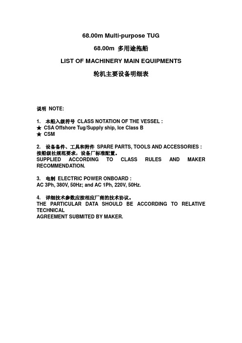
Cylinder quantity:12
缸径/行程Bore/Stroke:159/159mm
额定功率Rated power:560kW
额定转速Rated speed:1500rpm
燃油消耗率Fuel consumption:196g/kW.h
燃油品质Fuel quality:-10号、0号轻柴油
燃油消耗率Fuel consumption:205g/kW.h
燃油品质Fuel quality:
轻柴油及重油(180cst/50℃), MGO
and HFO (180cst/50℃)
滑油消耗率Lubricating oil consumption:1.7g/kW.h
起动方式Start method:3.0MPa压缩空气compressed air
河北恒盛泵业有限公司
CCS证书
certificates
型号Model:KYDH204SD-23
型式Type:自动排渣
有效分离量Effective quantity:550L/h
随配供给泵、电加热器及控制箱等With supply pumps, electric heaters and control boxes etc.
额定电压Rated voltage:400V – 3PH
频率Frequency:50Hz
7.燃油热水锅炉
Fuel oil water heater boiler
1套
set
无锡威力特船用锅炉有限公司
CCS证书
certificates
型号Model:LRS250-0.5
设计压力Design pressure:0.6MPa
68.00m Multi-purpose TUG
南阳防爆箱式电机样本(1)

南阳防爆箱式电机样本(1)YKK、YKS、Y系列高速高压三相异步电动机(机座号355~710、极数2、4P)产品样本代号:0AP.138.0150南阳防爆集团股份有限公司2013年1月尊敬的顾客:首先,感谢您关心和支持我公司的电动机产品,在您采购选用电动机之前,请您先仔细阅读《产品样本》,它会告诉您电动机产品的基本常识和如何选取您所需要的电动机,以便准确采购,使其更好地为您服务。
1 概述YKK、Y、YKS 系列高速高压三相异步电动机(机座号355~710、极数2、4P)(以下简称为电动机),是结合本公司长期稳定的高压三相异步电动机系列的设计制造经验而开发的新一代产品,是Y 系列的升级换代产品,是本公司在各个领域为您提供最合适的高品质、高性价比的电动机。
该系列电动机高效、节能、环保,具有中心高更低、功率更大、效率更高、噪声更低,运行安全可靠、使用维护方便等特点。
适用于驱动各种通风机、压缩机、水泵、破碎机、切削机械、运输机械、通用机械机其它机械设备,在矿山、钢铁、机械、石油、化工、电站等各种工况企业中作原动力用。
无论户内、户外,高原性气候或湿热型气候,该系列高压三相异步电动机总能提供超越卓群的驱动力,得到了用户的信赖和推崇。
2 优势、特点2.1 结构紧凑、型谱高、机座号低所有用户都希望其驱动系统能可靠运行,在有限的空间中输出功率更大,南阳防爆集团股份有限公司多年以来,通过降低电动机中心高与国外技术接轨,专注于实现电动机更小的尺寸、结构紧凑、更高的性能和可靠性,并获得了成功。
从型谱对比看,同功率的升级换代产品比原系列中心高降低1~2个机座号,如YKS710-2、4P6KV电动机最大容量可以到达8000KW,详细型谱见附件1。
2.2 高效、节能该系列高压电动机以其完善的设计、制造实现了高效节能的目标,效率符合“节能产品惠民工程”高效电机推广和国家高压电动机能效 2 级要求。
以YKS710-4 7100KW 10KV 电动机为例:现系列效率97.2%,GB13957-2008 规定原系列96.5%,用现系列该台电动机年减少电能消耗:(7100/0.965-7100/0.972) ×24×365=46.42万度,以每度电0.8元计算,节约金额46.42×0.8=37万元,节能效果显著,大幅度降低电动机运行成本。
南阳防爆箱式电机样本(1)

南阳防爆箱式电机样本(1)YKK、YKS、Y系列高速高压三相异步电动机(机座号355~710、极数2、4P)产 品 样 本代号:0AP.138.0150南阳防爆集团股份有限公司2013年1月尊敬的顾客:首先,感谢您关心和支持我公司的电动机产品,在您采购选用电动机之前,请您先仔细阅读《产品样本》,它会告诉您电动机产品的基本常识和如何选取您所需要的电动机,以便准确采购,使其更好地为您服务。
1 概述YKK、Y、YKS系列高速高压三相异步电动机(机座号355~710、极数2、4P)(以下简称为电动机),是结合本公司长期稳定的高压三相异步电动机系列的设计制造经验而开发的新一代产品,是Y系列的升级换代产品,是本公司在各个领域为您提供最合适的高品质、高性价比的电动机。
该系列电动机高效、节能、环保,具有中心高更低、功率更大、效率更高、噪声更低,运行安全可靠、使用维护方便等特点。
适用于驱动各种通风机、压缩机、水泵、破碎机、切削机械、运输机械、通用机械机其它机械设备,在矿山、钢铁、机械、石油、化工、电站等各种工况企业中作原动力用。
无论户内、户外,高原性气候或湿热型气候,该系列高压三相异步电动机总能提供超越卓群的驱动力,得到了用户的信赖和推崇。
2 优势、特点2.1 结构紧凑、型谱高、机座号低所有用户都希望其驱动系统能可靠运行,在有限的空间中输出功率更大,南阳防爆集团股份有限公司多年以来,通过降低电动机中心高与国外技术接轨,专注于实现电动机更小的尺寸、结构紧凑、更高的性能和可靠性,并获得了成功。
从型谱对比看,同功率的升级换代产品比原系列中心高降低1~2个机座号,如YKS710-2、4P 6KV电动机最大容量可以到达8000KW,详细型谱见附件1。
2.2 高效、节能该系列高压电动机以其完善的设计、制造实现了高效节能的目标,效率符合“节能产品惠民工程”高效电机推广和国家高压电动机能效2级要求。
以YKS710-4 7100KW 10KV电动机为例:现系列效率97.2%,GB13957-2008规定原系列96.5%,用现系列该台电动机年减少电能消耗:(7100/0.965-7100/0.972)×24×365=46.42万度,以每度电0.8元计算,节约金额46.42×0.8=37万元,节能效果显著,大幅度降低电动机运行成本。
IP44安全运行指南说明书

Safe Operation1. Check the rating label for voltage and frequency before connecting this luminaire to the electrical supply.2. Ensure that the mains supply is switched off when working on this luminaire, whether installing or carrying out any other servicing.3.To prevent damage to driver, do not mix with conventional magnetic ballasts on the same electrical circuit.4. Where use in more onerous situations is required, e.g. In part-completed buildings before “drying-out”is completed, or areas where ambient temperatures are outside the normal temperature range, then consult our Sales Office.Servicing and Disposal1.At commissioning and handing over of installation ensure that a copy of these instructions is presented to the authority responsible for the operation and maintenance of the luminaries.2. Servicing, e.g. cleaning, must only be carried out after the electricity supply has been switched off. It must not be assumed that luminaries with lamps not lit are switched off-always check before servicing.3. Cleaning should be carried out at regular intervals to ensure that dirt does not accumulate to an extent that will impair the thermal safety or optical performance of the luminaire. Regular cleaning will also ensure that the optical performance of the luminaries is maintained.4.Avoid touching the LED array surface.To clean - Blow surface with either dry air or nitrogen gas.5.At the end of life the luminaire is classed as WEEE under directive 20//E and should be disposed 12 19U of in accordance with local legislation.K1145VLuminaire CleaningEnd of Life and Components DisposalNote :The LED’s are non-replaceable but the batteries can be replaced by a competent personEatonWheatley Hall Road, Doncaster, South Yorkshire, DN2 4NBSalesT: +44 (0)1302 303303F: +44 (0)1302 367155E:*******************General+44 (0)1302 321541+44 (0)1302 303220***********************International Sales +44 (0)1302 303250+44 (0)1302 303251********************Instruction Manual -K1145V November 2017VersaPanel 625。
马拉松发电机IP44样本

IP44船用无刷三相交流发电机一、产品概述MP-H(IP44),MX-H(IP44)系列船用同步无刷三相交流发电机是在美国马拉松电气公司提供技术和图纸基础上,新开发设计的高防护等级船用发电机。
其基本部分(定子、转子)按照美国马拉松电气公司提供的图纸和工艺技术制造。
发电机上面带有水冷却器,与发电机一起组成封闭式结构。
二、卓越的电器性能1.稳态调压率≤1%2.顺态调压率+20%-15%Un(60%In.cosφ≤0.4滞后)3.电压调节范围>±10%Un4.线压波形正弦性畸变率<5%5.热偏差为零(极微)三、独特的结构设计1.发电机为全封闭式结构,发电机上面带有水冷却器,发电机出风口排出的热风通过冷却器冷却后进入发电机的进风口,构成一次循环。
冷却水通过水泵增压后从冷却器的进水口流入通过冷却水管把热量带走,从冷却器的出水口流出,构成二次循环。
2.无刷励磁方式,配有固态电压调压器,调压器具有低速保护,电磁干扰抑制,过励关断等功能,且带有稳定性调节和电压幅度调节。
3.整体凸极转子结构,阻尼绕组与转子铁心连成为一体,磁场绕组采用热固性环氧填充,有较高的机械和电气强度。
4.旋转整流器位于励磁机转子外侧,便于维修。
5.出线箱宽敞,内部可加装各种器件。
出线箱位于机座后面上方,美观紧凑。
6.绝缘等级为H级。
7.按客户要求可提供用于并联运行的模块及附加装置。
8.发电机分单轴承和双轴承两中结构。
单轴承带有国际标准的SAE接口和联轴器片,能与各类进口油机配套。
双轴承适应国内各种柴油机的配套,按客户要求配置各种尺寸的凸缘止口。
9.根据客户需要可以加装PMG及使用DVR2000E数字式调压器。
10.根据客户需要可以加装防冷凝加热管和热保护元件。
四、使用条件:空气温度不超过:45℃水冷却温度不超过:30℃海拔高度不超过:1000米如使用条件不符合上述环境,必须按规定修正功率输出定额。
电压、频率、转速、功率因数及工作方式:额定电压:400伏(480伏60赫兹时)额定频率:50赫兹或60赫兹额定转速:1500转/分或1800转/分功率因数:0.8滞后工作方式:连续(S1)根据客户需要,可制成不同输出电压,或其它特殊要求的产品。
Y系列电机

功率范围 0UTPUT RANGE4极--11~315千瓦(15~425马力)4poles--11~315KW (15~425HP) 6极--7.5~250千瓦(10~340马力)6poles--7.5~250KW(10~340HP) 8极--4~200千瓦(5.5~270马力)8poles--4~200KW(5.5~270HP) 10极--45~75千瓦(60~100马力)10poles--45~75KW(60~100HP)技术条件TECHNICAL CONDTTION(1)额定电压:380伏Rated voltage:380V(2)额定频率:50赫芝(3)防护等级:IP44(4)工作方式:连续S1(5)接法:3千瓦(4马力)及以下者为Y接法,4千瓦(5.5马力)及以上者为△接法。
(6)绝缘等级:B级(7)工作条件环境温度不超过+40℃,海拔不超过1000米,相对温度不超过95%。
Rated frequency:50HzProtection class:IP44Rating: Continuous:S1Connections:Star--below 3KW(4HP)Delta--4KWZ(5.5HP)or moreInsulation class:B classService condition:Y series motors are commonly designed for operation atan ambient temperature of not exceeding + 40℃。
an altitudenot over 1000m above sea level and a relative humidity airnot higher than 95 % .结构型式CONSTRUCTIONAL TYPE有三种基本结构型式:B3型--机座带底脚,端盖无凸缘的结构型式。
B5型--机座不带底脚,端盖上带大于机座的凸缘的结构型式。
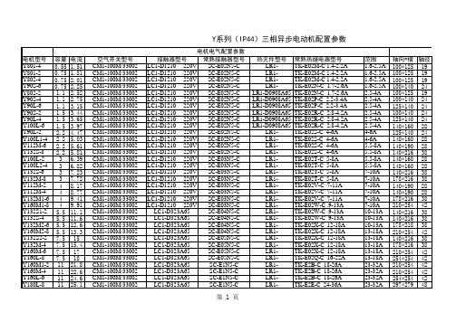
IP44三相异步电动机配置参数
- 1、下载文档前请自行甄别文档内容的完整性,平台不提供额外的编辑、内容补充、找答案等附加服务。
- 2、"仅部分预览"的文档,不可在线预览部分如存在完整性等问题,可反馈申请退款(可完整预览的文档不适用该条件!)。
- 3、如文档侵犯您的权益,请联系客服反馈,我们会尽快为您处理(人工客服工作时间:9:00-18:30)。
IP44船用无刷三相交流发电机一、产品概述MP-H(IP44),MX-H(IP44)系列船用同步无刷三相交流发电机是在美国马拉松电气公司提供技术和图纸基础上,新开发设计的高防护等级船用发电机。
其基本部分(定子、转子)按照美国马拉松电气公司提供的图纸和工艺技术制造。
发电机上面带有水冷却器,与发电机一起组成封闭式结构。
二、卓越的电器性能1.稳态调压率≤1%2.顺态调压率+20%-15%Un(60%In.cosφ≤0.4滞后)3.电压调节范围>±10%Un4.线压波形正弦性畸变率<5%5.热偏差为零(极微)三、独特的结构设计1.发电机为全封闭式结构,发电机上面带有水冷却器,发电机出风口排出的热风通过冷却器冷却后进入发电机的进风口,构成一次循环。
冷却水通过水泵增压后从冷却器的进水口流入通过冷却水管把热量带走,从冷却器的出水口流出,构成二次循环。
2.无刷励磁方式,配有固态电压调压器,调压器具有低速保护,电磁干扰抑制,过励关断等功能,且带有稳定性调节和电压幅度调节。
3.整体凸极转子结构,阻尼绕组与转子铁心连成为一体,磁场绕组采用热固性环氧填充,有较高的机械和电气强度。
4.旋转整流器位于励磁机转子外侧,便于维修。
5.出线箱宽敞,内部可加装各种器件。
出线箱位于机座后面上方,美观紧凑。
6.绝缘等级为H级。
7.按客户要求可提供用于并联运行的模块及附加装置。
8.发电机分单轴承和双轴承两中结构。
单轴承带有国际标准的SAE接口和联轴器片,能与各类进口油机配套。
双轴承适应国内各种柴油机的配套,按客户要求配置各种尺寸的凸缘止口。
9.根据客户需要可以加装PMG及使用DVR2000E数字式调压器。
10.根据客户需要可以加装防冷凝加热管和热保护元件。
四、使用条件:空气温度不超过:45℃水冷却温度不超过:30℃海拔高度不超过:1000米如使用条件不符合上述环境,必须按规定修正功率输出定额。
电压、频率、转速、功率因数及工作方式:额定电压:400伏(480伏60赫兹时)额定频率:50赫兹或60赫兹额定转速:1500转/分或1800转/分功率因数:0.8滞后工作方式:连续(S1)根据客户需要,可制成不同输出电压,或其它特殊要求的产品。
五、型号说明:三相无刷交流发电机)MP-H,MX-H发电机都可连续并联运行,为保证发电机运行稳定,转子上都装有全阻尼绕组。
发电机并联运行时,有功负载的分配由柴油机调速器调节,无功负载的分配由发电机调压器实现。
配有SE350调压器的发电机并联运行时,需配有APM2000并联模块和5VA的电流互感器,采用电压下垂或横流补偿来保证并联发电机之间无功负载分配的均衡。
配有PMG 和DVR2000E 调压器的发电机由于DVR 调压器中包含可并联运行的功能,只需要供5VA 电流互感器的信号给调压器即可。
六、抗电磁干扰:装有SE350调压器的发电机符合普通级,配DVR2000E 数字式调压器的发电机符合Mil-461c 第九部分(美国军用标准)七、轴承:MP-H ,MX-H 发电机使用的轴承是双面防尘滚动球轴承,一次性润滑,特殊的高性能润滑脂:正常使用情况下,B10≥20000小时。
八、机座号说明: 机座号FRAME 型号TYPE额定功率(KW) 调压器 VR 额定转速(rpm) 50HZ 60HZ 430 MP-H-120-4120 SE350 1500 1800 MP-H-150-4150 MP-H-200-4200 MP-H-250-4250 MP-H-300-4300 500 MP-H-350-4350 MP-H-400-4400 MP-H-480-4480 570 MX-H-500-4500 DVR2000EMX-H-600-4 600备注:430、500机座发电机可按客户要求配置PMG 励磁系统和DVR2000E 数字式调压器。
本样本内容更改时,不另行通知。
本公司对本样本拥有最终解释权。
IP44 Marine GeneratorsⅠ. Summary:MP-H(IP44), MX-H(IP44)SERIES MARINE SYNCHRONOUS BRUSHLESS 3-PHASE ALTERNATORS ARE NEWLY DISIGNED HIGH-PROTECTION MARINE GENERATORS BASED ON THE TECHNOLOGY AND DRAWINGS FROM USA MARATHON CO., LTD. THE PRIMARY PARTS (STATOR & ROTOR) ARE MANUFACTURED ACCORDING TO THE TECHNICAL PROCESS OF USA MARATHON CO., LTD. THE GENERATOR WITH A WATER COOLER UPON IT FORMS A CLOSE-DOWN STRUCTURE.Ⅱ.Outstanding Electric Characteristics:1. STEADY VOLTAGE REGULATION IS LESS THAN 1%.2. TRANSIENT VOLTAGE REGULATION IS LESS THAN +20%, -15% (60% In,P.F 0.4 LAG).3. VOLTAGE ADJUSTING RANGE IS OVER THAN 10% OF UN.4. TOTAL VOLTAGE WAVEFORM DISTORTION IS LESS THAN 5% (L-L).5. THERMAL WARP: APPROXIMATELY ZERO.Ⅲ.Unique Structure:1. FULL CLOSE-DOWN STRUCTURE. THERE IS A WATER COOLER UPONTHE GENERATOR. HOT WIND FROM THE EXIT OF GEN AIR-VENT GOESTHROUGH COOLER AND INTO THE ENTRANCE OF GEN AIR-VENT, WHICHIS THE FIRST CYCLE. PRESSED BY PUMP, COOLING WATER INPOURSFROM THE ENTRANCE OF COOLER WATER-VENT AND TAKE THE HEATOF WATER TUBES AWAY, THEN EFFUSE THROUGH COOLER, WHICH ISTHE SECOND CYCLE.2. BRUSHLESS EXCITATION WITH SOLID-STATE CIRCUIT AVR, (SE350)WHICH IS ENCAPSULATION FOR MOISTURE AND VIBRATION PROTECTION.3. UNIROTOR CONSTRUCTION WITH FULL DAMPING WINDING (DIE CAST),FIELD WINDINGS ARE LAYER WOUND WITH THERMO-SETTING EPOXYFOR MECHANICAL AND ELECTRICAL INTEGRITY.4. STATOR WINDING OF 2/3 PICH, MINIMIZE HARMONIC DISTORTION.5. H CLASS INSULATION SYSEM.6. RECTIFIER ASSY. LOCATED OUTBOARD OF THE EXCITER FOR EASYSERVICE.7. CONDUIT BOX IS MOUNTED ON THE TOP OF FRAME. THE ACCESSARIESCAN BE INSTALLED IN THE AMPLE BOX.8. PARALLELING MODULE & ACCESSARIES CAN BE ASSEMBLED ASCUSTOMER REQUESTED.9. PMG & DVR2000E CAN BE ASSEMBLED AS CUSTOMER REQUESTED.10. HEATER AND THERMAL PROTECTION ELEMENT CAN BE ASSEMBLED ASCUSTOMER REQUESTED.Ⅳ. Operation Environment:℃1. AMBIENT TEMPERATURE ≤ 45.℃2. COOLING WATER TEMPERATURE ≤ 30.3. ALTITUDE ≤ 1000m.NOTE: IF THE ENVIROMENT CONDITION IS HIGHER OR DIFFERENT FROM ABOVE REQUIREMENTS, THE OUTPUT POWER SHOULD REFER TO CORRESPONDING DECREATED TABLE.Volts, Hz, rpm, PF & Working:1. RATING VOLATGE: 400V (480V, 60Hz)2. RATING FREQUENCY: 50Hz OR 60Hz3. RATING REV: 1500 RPM OR 1800 RPM4. P.F: 0.8 LAG5. WORKING: CONTINUOUS DUTY (S1)ACCORDING TO THE REQUREMENTS OF CUSTOMERS, WE CAN OFFER DIFFERENT KIND OF RATING VOLATGE. ALSO WE CAN SUPPLY OTHER SPECIAL GENERATORS TO MEET MARKET DEMANDS.Ⅴ. Type Description:MP-H, MX-H SERIES GENS CAN OPERATE WHEN PARALLELING. IN ORDER TO KEEP GENS WORKING STEADILY, ROTORS ARE EQUIPED WITH FULL DAMPINGWINDINGS.WHEN GEN PARALLELING OPERATES, ACTIVE LOAD SHARING IS CONTROLED BY THE SPEED PANEL OF DIESEL ENGINE AND REACTIVE LOAD SHARING IS CONTROLED BY THE VOLTAGE REGULATOR OF GEN.WITH SE350 VOLTAGE REGULATOR, GEN MUST BE FURNISHED WITH APM2000 PARALLEL MODULE AND 5VA CURRENT MUTUAL INDUCTOR TO OPERATE PARALLELING. REACTIVE DROOP COMPENSATION IS USED TO ASSIST IN THE SHARING OF REACTIVE LOAD DURING PARALLEL GEN OPERATION.AS DVR2000E WITH PARALLEL FUNCTION, WITH DVR2000E VOLTAGE REGULATOR & PMG, GEN CAN DO PARALLEL OPERATION ONLY FURNISHED WITH 5VA CURRENT MUTUAL INDUCTOR.Ⅵ. Resistant to Electromagnetism:GEN FURNISHED WITH SE350 MEASURES UP NORMAL STANDARD. GEN FURNISHED WITH DVR2000E MEASURES UP Part 9 of Mil-461c (USA MILITARY STANDARD).Ⅶ. Bearing:DOUBLE SHIELDED & PRE-LURICATED BEARING FOR HIGH LIFE (B10, OVER THAN 20000 HOURS). SINGLE IS 6314ZZ.NOTE: ANY CHANGES, NO NOTICE.。
