ER1001FCT-G中文资料
ER1002FCT中文资料
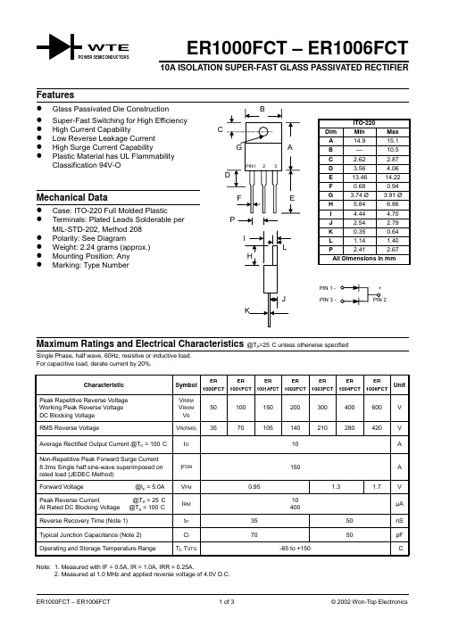
ER1000FCT – ER1006FCT10A ISOLATION SUPER-FAST GLASS PASSIVATED RECTIFIERSingle Phase, half wave, 60Hz, resistive or inductive load.For capacitive load, derate current by 20%.Characteristic Symbol ER1000FCTER1001FCTER1001AFCTER1002FCTER1003FCTER1004FCTER1006FCTUnitPeak Repetitive Reverse Voltage Working Peak Reverse Voltage DC Blocking Voltage V RRMV RWMV R50100150200300400600VRMS Reverse Voltage V R(RMS)3570105140210280420V Average Rectified Output Current @T C = 100°C I O10A Non-Repetitive Peak Forward Surge Current8.3ms Single half sine-wave superimposed onrated load (JEDEC Method)I FSM150A Forward Voltage @I F = 5.0A V FM0.95 1.3 1.7VPeak Reverse Current @T A = 25°C At Rated DC Blocking Voltage @T A = 100°C I RM10400µAReverse Recovery Time (Note 1)t rr3550nS Typical Junction Capacitance (Note 2)C j7050pF Operating and Storage Temperature Range T j, T STG-65 to +150°C Note: 1. Measured with IF = 0.5A, IR = 1.0A, IRR = 0.25A.2. Measured at 1.0 MHz and applied reverse voltage of 4.0V D.C.WTE3060900120150180110100I ,P E A K F O R W A R D S U R G E C U R R E N T (A )F S M NUMBER OF CYCLES AT 60HzFig.3Max Non-Repetitive SurgeCurrent10100400V ,REVERSE VOLTAGE (V)Fig.4Typical Junction CapacitanceRC ,C A P A C I T A N C E (p F )j 0246810050100150I ,A V E R A G E F O R W A R D C U R R E N T (A )(A V )T ,CASE TEMPERATURE (C)Fig.1Forward Current Derating CurveC °0.11.0101000.20.61.01.4I ,I N S T A N T A N E O U S F O R W A R D C U R R E N T (A )F V ,INSTANTANEOUS FORWARD VOLTAGE (V)Fig.2Typical Forward CharacteristicsFORDERING INFORMATIONProduct No.Package TypeShipping QuantityER1000FCT ITO-22050 Units/Tube ER1001FCT ITO-22050 Units/Tube ER1001AFCT ITO-22050 Units/Tube ER1002FCT ITO-22050 Units/Tube ER1003FCT ITO-22050 Units/Tube ER1004FCT ITO-22050 Units/Tube ER1006FCTITO-22050 Units/TubeShipping quantity given is for minimum packing quantity only. For minimum orderquantity, please consult the Sales Department.Won-Top Electronics Co., Ltd (WTE) has checked all information carefully and believes it to be correct and accurate. However, WTE cannot assume any responsibility for inaccuracies. Furthermore, this information does not give the purchaser of semiconductor devices any license under patent rights to manufacturer. WTE reserves the right to change any or all information herein without further notice.WARNING : DO NOT USE IN LIFE SUPPORT EQUIPMENT. WTE power semiconductor products are not authorized for use as critical components in life support devices or systems without the express written approval.We power your everyday.Won-Top Electronics Co., Ltd.No. 44 Yu Kang North 3rd Road, Chine Chen Dist., Kaohsiung, Taiwan Phone: 886-7-822-5408 or 886-7-822-5410Fax: 886-7-822-5417Email: sales@Internet: 。
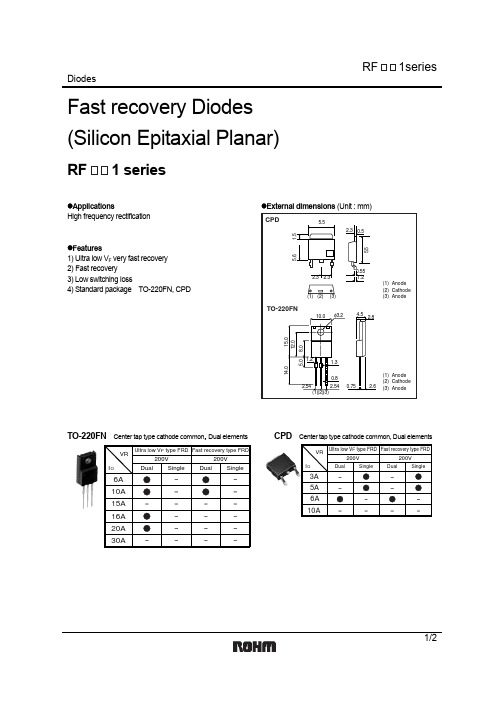
RF1001T2D中文资料
2/2
元器件交易网
Appendix
Notes
No technical content pages of this document may be reproduced in any form or transmitted by any means without prior permission of ROHM CO.,LTD. The contents described herein are subject to change without notice. The specifications for the product described in this document are for reference only. Upon actual use, therefore, please request that specifications to be separately delivered. Application circuit diagrams and circuit constants contained herein are shown as examples of standard use and operation. Please pay careful attention to the peripheral conditions when designing circuits and deciding upon circuit constants in the set. Any data, including, but not limited to application circuit diagrams information, described herein are intended only as illustrations of such devices and not as the specifications for such devices. ROHM CO.,LTD. disclaims any warranty that any use of such devices shall be free from infringement of any third party's intellectual property rights or other proprietary rights, and further, assumes no liability of whatsoever nature in the event of any such infringement, or arising from or connected with or related to the use of such devices. Upon the sale of any such devices, other than for buyer's right to use such devices itself, resell or otherwise dispose of the same, no express or implied right or license to practice or commercially exploit any intellectual property rights or other proprietary rights owned or controlled by ROHM CO., LTD. is granted to any such buyer. Products listed in this document use silicon as a basic material. Products listed in this document are no antiradiation design.
海底车辆光纤管切割器HCV1 00 产品说明书

HOSE/UMBILICAL CUTTER HCV100PRODUCT CODE No. 980292INSTRUCTIONS FOR INSTALLATION,OPERATION & MAINTENANCERevision 12 issue 1. Modification No. 20658 Date 15TH. Nov 2013 © Copyright Allspeeds Holdings Ltd.This document must not be modified in any way.DescriptionThe HCV100 is a lightweight double acting cutting tool primarily intended for use on umbilical cable and hose and will cut up to 100mm diameter. It may be used on alternative materials, such as electrical power or communication cables, again up to a maximum of 100mm diameter. It may be mounted on an ROV or manipulator arm.Where small diameters are to be cut, every effort should be made to place the material centrally along the anvil to minimize offset loading. The anvil can be automatically withdrawn to allow placement. The cutter is not designed to cut wire rope.1. S AFETYBefore operation, read and understand this operations manual.Whilst the tool is intended for remote or local operation sub-sea, there is no reason why it should not be used above surface.Ensure that the tool, hoses and pump are in good condition and properly connected.Ensure that suitable pressure regulation equipment is used and that the unit is not subjected to pressures higher than those stated in section 3In all cases, where an operator is present, the safety aspects must be reviewed before the cutting operation is commenced.No attempt should be made to cut any material that is under tension.Ensure that the operator is shielded from the cutting blade during the cutting operation.When cutting near the very end of hose or rope, individual cut wires can be expelled from the tool, please ensure that the operator is shielded from these.If in doubt please contact the manufacturer (Allspeeds Ltd) or an authorized distributor for assistance.If at any time it is necessary to carry out proof tests on the tool, e.g. after service on thehydraulic cylinders, it must be returned to the supplier for testing where the followingprocedures apply.The maximum proof test pressure should not exceed 125% of the maximum working pressure and this should only be done by Allspeeds using our specially adapted test rig.The tool should be guarded during the proof test operation, and be carried out ina safe working environment.The proof pressure should be applied gradually, until the maximum pressure is reached.INSPECT THE TOOL BEFORE USEWith the cutter isolated from the hydraulic supply, check the condition of the blade edge. If the blade is damaged or blunt replace with a fresh blade before cutting. This procedure is as described in section 8.Ensure that care is taken when checking the blade as the edge may be sharpCheck the condition of the anvil. It is normal that the anvil will show an indent where the blade has pressed down into it and can withstand multiple cuts, but any excessively damaged anvil should be replaced. This procedure is as described in section 7Ensure that all retaining bolts are tightCAUTION – USE OF BLADES AND PARTS NOT APPROVED BY WEBTOOL MAY RESULT IN TOOL FAILURE ANDCONSEQUENTIAL DAMAGE2.C UTTING CAPACITYThe HCV100 is a double acting tool primarily intended for use on soft materials i.e. umbilical cable and hose and will cut up to 100mm diameter. It may be used on alternative materials, such as electrical power lines (inc double row armoured cable) or communication cables, again up to a maximum of 100mm diameter.Where small diameters are to be cut, every effort should be made to place the material centrally along the anvil to minimize offset loading. It is not intended for use on high tensile wire rope, chain or solid steel bar.N.B. If in doubt about the size and type of material to be cut please refer to the manufacturer. Failure to do so may result in permanent damage to the tool.3.I NSTALLATIONFour holes are provided in the tool body which can be used for any attachment necessary to mount the tool to an operating arm/vehicle. (See below). The cylinder is a pressure vessel and is not recommended as a mounting point, the cylinder should not be drilled, machined, mutilated or damaged in any way, any warranty could be invalidated by such actions.T wo hydraulic supplies are required, one at 640 Bar, usually through an intensifier, for the main ram and another at 190 Bar max. for the auxiliary cylinders.The main ram return is rated and tested for 640 Bar but may be operated from the low pressure supply if this is more convenient. T he maximum working pressures and port tappings are shown below.Note - A relief valve should also be incorporated in the return line. This is to prevent excessively high pressures in the annular side of the hydraulic cylinders should the return to tank become blocked for any reason.The oil supply must be clear and free from contamination. A good quality ISO32 grade hydraulic oil, e.g. Shell Tellus 32 or equivalent, is suitable.The weight of the tool is 28.5Kg.Table 1.* N.B. Actual Pressure Required To Return Ram < 15 Bar (4. OPERATIONBefore deployment, function test the tool and ensure that all operators are familiar with this procedure. If used with an ROV or similar equipment, observation of the tool should be maintained at all time during operation.Prior to use, ensure no damage has occurred to the blade or anvil. Ensure the anvil is fully retracted.Important: Please note this tool is designed for intermittent subsea use. Please refer to the manufacturer (Allspeeds Ltd) or an authorized distributor should you wish to use this tool subsea for any period over 14 days.CAUTION – Any modification made to this tool will invalidate the warranty and may lead to equipment failure or personal injury. If in doubt please contact the manufacturer (Allspeeds Ltd) or an authorised distributor for assistance.DEPLOYMENTPlace the cutter over the material. Ensure that the material is as far into the cutteras possible.Pressurize the auxiliary cylinders to fully extend the anvil, thus retaining the materialin the body of the tool. Check visually that the anvil is fully home, this is important to preventdamage to the tool.Operate the main ram power port to sever the material, hold pressure until the material issevered.N.B. Do not operate the auxiliary cylinders when the main ram is fully extended since this woulddamage the anvil.Once the material is severed, pressurize the main ram retract port to withdraw the cuttingblade. Then, and only then, retract the anvil. It is important not to operate the auxiliarycylinders whilst the main ram and blade are in the fully extended position.If a further cut is required, the above procedure should be repeated.TROUBLESHOOTINGIf the material does not cut through completely on the first attempt, cycle the blade byretracting it slightly and then attempting the cut again.If the material does not completely cut after multiple cycles of the blade, check the inputpressure to the main input of the cylinder. This can be a maximum of 640 bar (9,280psi).If the material to be cut is still not severed after multiple cycles and at a pressure of 640 bar,retract the blade and then the anvil and return the tool to the surface for inspection of theblade and anvil, replace if necessary.IMPORTANT NOTE – ENSURE THAT THE BLADE IS FULLY RETRACTED AND THAT ALL PRESSURETO THE CUTTER IS RELIEVED AS IT IS RAISED TO THE SURFACE. FAILURE TO DO THIS CAN LEADTO A DANGEROUS BUILD UP OF PRESSURE IN THE CYLINDER.5. AFTER USEWhen the tool is retrieved from a marine environment, it should be hosed off with clean water, allowed to drain and sprayed externally with a de-watering fluid. Before storage, inspect the general condition of the tool. Particular attention should be paid to the anvil and blade. The anvil should be clean and free from any damage or bruising on the outside diameter that would prevent it from retracting properly, The blade edge should be smooth and free from any serrations. Note that a slight ripple to the blade edge is acceptable and will not cause problems. Any minor damage can be smoothed off with an oil stone if necessary.IMPORTANT – DO NOT STORE THE TOOL WITH A COMPLETELY SEALED CYLINDER AS PRESSURE MAY BUILD UP DUE TO TEMPERATURE CHANGES.6. SERVICEIMPORTANT – ENSURE THERE IS NO HYDRAULIC PRESSURE IN THE CYLINDER BEFOREPERFORMING ANY SERVICE OR MAINTENANCE PROCEDURES ON THIS CUTTERIt is unlikely that service would be required on the hydraulic components of the tool under normal circumstances, but a seal spares kit is available if required. The only parts that would need intermittent replacement would be the anvil and blade, depending on the frequency of use and materials being cut. These parts can be ordered up on the following spares reference numbers, but in addition please quote the tool serial number.HCV100 seal kit for cutter and auxiliaries Part Number 995291Anvil Part Number CC6378Blade Part Number 705010cBlade Retaining Pin Part Number 030648 3 offWe advise that any servicing should be carried out by an authorised distributor only.If required, the tool can be returned to the manufacturer, Allspeeds Ltd, for servicing and testing.If servicing is to be undertaken by the user, please see note on proof testing underSAFETY (Section 1), and the following:-All servicing operations should be carried out in a clean environment to prevent contamination of the oil and mating components.Care should be taken with all mating areas ie. threads and sealing faces, as any damage or abrasive contamination could cause galling or seizing on re-assembly.The cylinder is a pressure vessel and should not be drilled, machined, mutilated or damaged in any way for mounting purposes or to assist in its removal for servicing, any warranty could be invalidated by such actions. Also see section 9The use of stilsons to remove the cylinder is not recommended as damage will occur.7. REPLACEMENT OF THE ANVILTo remove the anvil, follow this procedure:D isconnect the anvil CC6378 from the anvil bracket 765179 by removing the spring pin 030820. The anvil can then be passed through the body and removed.To replace the anvil the reverse is required.8. REPLACEMENT OF THE BLADETo remove the blade, follow this procedure:To remove the blade 705010c, ensure the anvil CC6378, has been fully retracted in the anvil guide bush 715300, pump out the main ram 764060 until the three ¼" diameter blade-pins 030648 are accessible. Drift out the blade pins, the blade, supported in the blade guideplates, will now slide out of the tool.To replace the blade the reverse is required.9. REMOVAL OF MAIN CYLINDERIf it is necessary to renew the hydraulic seals, first remove the blade 705010C as described above in section 8, the cylinder must then be removed from the tool. As an aid to this, remove the 2 blanking screws 035080, then a bar is to be fastened to the top of the cylinder using the 2 tapped holes, apply a torque and not a bending moment when unscrewing the cylinder. The cylinder is a pressure vessel and should not be drilled, machined, mutilated or damaged in any way for mounting purposes or to assist in its removal for servicing, any warranty could be invalidated by such actions. Do not use Stilsons to remove the cylinder as damage will occur.A cylinder assembly tool is available as an optional extra part, number SK4377A10. REMOVAL OF THE AUXILIARY CYLINDERSFirst remove the hoses from the auxiliary cylinders. Remove the set screw 035091 from the end of the piston block709606, unscrew the clevis bolt 011011, the auxiliary cylinder 982118 will now come away from the cutter body.11. R EMOVAL OF THE AUXILIARY SEALSFirst, remove the auxiliary cylinder assembly from the cutter body. Remove the 4 screws 035067 to free the end cap SSC6476, remove the set screw 035062 to allow the piston block 709062 to be unscrewed, under the screw 035062 is an aluminium pellet 026701, this is used to prevent the screw damaging the thread on the piston, the piston can now be removed, all seals are now accessibleAssembly shown below with cylinder body 728029 and piston block 709606 removedPART No.DESCRIPTION Qty.710 177 Body 1728 027 Cylinder, main 1764 060 Ram 1774 020 Bearing ring 1CC6378 Anvil 1715 300 Bush, anvil guide 1715 301 Bush, anvil 1709 047 Block, sliding 2765 121 Guide plate, blade 2701 187 Adaptor 1011 011 Bolt, clevis 2035 061 Screw, sliding block 2080 956 Washer 2705 010c Blade 1025 570* Scraper, ram 1025 756* 'O' ring 1025 803* Seal, main cylinder 1025 804* Seal, ram 1043 206 Screw, socket set, anvil bush 1035 080 Screw, sock set, main cylinder 2035 064 Screw, socket cap, blade guide 16030 648 Pin, spring, blade 3030 820 Pin, spring, anvil 1982 118 Cylinder, lever 2765 179 Bracket, anvil 1761 231 Clevis pin 1761 230 Pivot pin 1761 232 Spacer pin 1765 178 Frame legs 2080 978 Washers, spacer pin 2035 091 Screw, socket set, clevis pin 21240010 Bush 4035 092 Screw, socket cap, spacer pin 2035 073 Screw, socket set, pivot pin 2766 047 Blanking plug 6752 342 Nameplate 1752 569 Pressure warning label 1 ºN.B. Parts Marked Thus * Are in Seal KitPART No. DESCRIPTION QTY709 606Piston block1728 029Cylinder, lever1SSC6476End cap1764 102Piston1026 701Pellet, Aluminium1025 311*'O' ring, end cap1025 569*Scraper, rod1025 801*Seal piston1025 802*Seal, rod 1043 206*Screw, socket set, piston block1035 067Screw, socket cap4 N.B. Parts marked thus * are in seal kitThis HCV100 cutter is compatible with the following optional extras, not supplied as standard.Cylinder Assembly Tool - SK4377AThis tool can be used on RCV75, RCV75HD, RCV115, RCV135, RCV155, RCV190, HCV100, HCV120, HCV250 and HCV270 cutting toolsWebtool Hydraulic Intensifier – HP690A (available in a range on intensification ratios)For further information contact the manufacturer (Allspeeds Ltd) or an authorised distributor.Anvil Retract Spring Kit – 995111 Also available as an add on for this cutter, the anvil lever frame would need to be drilled and tapped to attach this kitCUTTING EDGE TECHNOLOGYWebtool specialises in engineering powerful hydraulic tools for cutting and grippingrope, cable and umbilicals.Models designed for use in subs ea environments by ROV’s, and surface applicationsin hostile environments.∙Wire rope cutters (WCS and WCOS) – capable of cutting steel wire rope up to 75mmdiameter∙Wire Rope Cutters (RCV) – capable of cutting steel wire rope up to 190mm diameter ∙Cable Cutters (HCV) – capable of cutting cable, umbilical and armoured flexible pipelines up to 330mm diameter∙Softline Cutters (SL) – capable of cutting fibre ropes in various sizes∙Wire Rope / Cable Grippers∙Wire Rope Clamps∙Automatic ShacklesApplication specific solutionsOur in house design and manufacturing capability means we can quickly andefficiently develop a solution to suit your particular application. Contact ourengineering department to discuss how we can help.Allspeeds Ltd, Royal Works, Atlas Street, Clayton-Le-Moors,Accrington, Lancashire, BB5 5LW, EnglandT: +44 (0)1254 615100 F: +44 (0)1254 615199E:*****************.uk W: 。
欧瑞E1000系列通用变频器使用手册
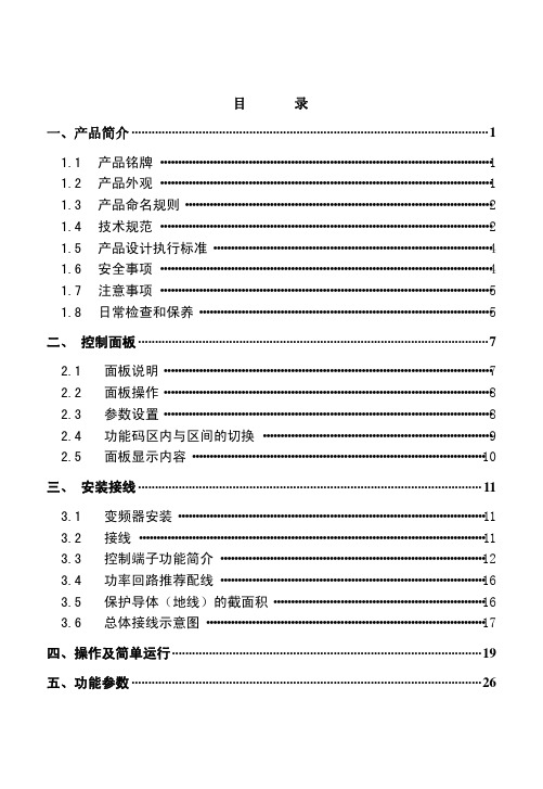
附录 4 通 讯 手 册 ···························································································64
图 1-1 产品铭牌
E1000 系列变频器外观结构为塑壳,采用壁挂式安装结构。塑料外壳采用优质材料模压而成,体 积小巧,造型美观且强度高、韧性好。
以 E1000-0007S2 为例,产品外形及结构部件如图 1-2 所示。
控制盒 通风栅 控制端子 功率端子
安装孔 散热器
图 1-2 产品外形及结构部件
1
三、 安装接线 ······································································································ 11
3.1 变频器安装······················································································· 11 3.2 接线 ·································································································· 11 3.3 控制端子功能简介 ··········································································· 12 3.4 功率回路推荐配线 ··········································································· 16 3.5 保护导体(地线)的截面积···························································· 16 3.6 总体接线示意图 ··············································································· 17
78 ZIEHL industrie-elektronik UFR1001E 电压频率监测器商品说明

Voltage Monitoring Type UFRThe grid- and plant protection de-vice UFR1001E monitors voltage and frequency in plants for own generation of electricity. It com-plies with the requirements of VDE-AR-N 4105:2018-11, VDE-AR-N 4110:2018-11, G98, G99, ÖVE/ÖNORM E 8001-4-712:2009 and other standards for generators connected to the public grid.The UFR1001E is a dual-channel device and thus one-fault-proof.Voltage and Frequency Relay UFR1001EGrid- and Plant Protection VDE-AR-N 4105 and 4110, ÖVE-standard, G98 + G99, DIN V VDE 0126-1-1, VFR2013/2014, NRS 0972-1:2017 Ed 2, Synergrid C10/C11UFR1001E••••••••NEW: VDE-AR-N 4105:2018-11, VDE-AR-N 4110:2018-11Part number:S222296The function of the output-relays and of the connected switches can be monitored with feed-back contacts. When a connected switch does not switch off, the UFR does not switch on again. When a switch does not switch on it makes 2 restarts and thus improves availability of monitored plant.The limits are pre-set according to VDE-AR-N 4105-2018-11, VDE-AR-N 4105:2018-11 and other standards. They can be changed if required and be protected with a code and/or a seal.With a 2-step test both channels can be tested indivi-dually and the triggering time of connected switches is measured.The standby input allows a remote shutoff e.g. with a RCR.Under and overvoltage monitoring 15…520 VMeasuring phase-neutral or phase-phaseMonitoring of under- and overfre-quency 45…65 HzMonitoring of quality of voltage (10-minutes-average)Monitoring of vector shift 2…65°Monitoring of rate of change of frequency (ROCOF, df/dt) 0,100...5,000 Hz/sOne-fault-proof with monitoring of connected switches (defeatable), 2 automatic restarts at errorPassive anti-islanding pro-tection acc. to ch. 6.5.3 and app. D2Switching delay adjustable 0.05 … 300 sSwitching back delay adju-stable 0 … 6.000 s Preset values acc. toVDE-AR-N 4105:2018-11 (Pr2), VDE-AR-N 4105-2011-08 (Pr1)VDE-AR-N 4110:2018-11 (PR11-14) and BDEW (Pr 3-6)G98 (G83/2) and G99 (G59/3) for Great Britain ÖVE standard for AustriaVSE/EEA-CH 2014 for SwitzerlandAlarm counter for 100 alarms (trip value, cause and rel. time stamp)Record of added times of alarmsInput for standby with counter and recording of time Test button and simulation with measuring of switching-timesSealing. All values can be read-out when sealed Easy installation and programming with pre-set programsHousing for DIN-rail-mount, 105 mm wide, mounting height 66 mm•••••••••••-----Certificate of conformity Grid and Plant protection acc. to VDE-AR-N 4105 2011-08 and 2018-11 "Plants for generati-on of own energy in low voltage grid"Cerfiticate of conformity Grid and Plant protection acc. to BDEW requirement "Plants for generation of own energy in medium voltage grid"Certificates:CertificateÖVE/ÖNORM E 8001-4-712:2009-12, Anhang ACertificate of compliance DIN V VDE 0126-1-1Certificate de conformitéDIN V VDE 0126-1-1, VFR2013/VFR 2014Certificate of complianceNRS 097-2-1:2010 ed 2.0 South Africa approved Synergrid C10/C11approved Energex RED STD00233accepted by TepcoCertificate of compliance EN 50438:2013Certificate of compliance G59/3:2013, G83/2:2012, G99/1-1+2+3:2018 and G98/1-1+2:2018RD1699:2011 / RD413:2014Technical Data UFR1001EVoltage Monitoring Type UFR2AC/DC 24-270 V, 0/45...65 Hz, <5VA DC: 20,4...297 V, AC: 20,4...297 V 2 change-over contacts see operating manualAC 15...530 V (< 5 V display: 0)AC 15...520 VAC 10...310 V (< 5 V display: 0)AC 15...300 V true RMSadjustable 1,0...180 Vwith neutral: ±0,6% of measured value without neutral: ±0,8% of measured value >100V: -1 digit (resolution 1 V) <100V: -1 digit (resolution 0,1 V)3-phase with / without neutraladjustable 0,05 (± 15ms)...300,0 sadjustable 0 (approx. 200 ms)...6.000 s 40...70 Hz45,00...65,00 Hz 0,05...10,00 Hz ± 0,04 Hz ± 1 digitadjustable 0,05 (± 15ms)...300,0 s adjustable 0 (>200 ms)...6.000 s 0...90,0°2,0...65,0°< 50 msadjustable 3...240 s adjustable 2...20 s0,100...5,000 Hz/s, 4...50 cycles DC 4,5...27 Vmax. 20 mA / output DC 15...35 Vadjustable 0,5...99,0 sEN 602554000 V III 2300 V 100 %-20 °C...+55 °C -25 °C...+70 °C3K5 (except condesation and formation of ice)EN 61 000-6-2EN 61 000-6-3V690 x 105 x 69 mm, mounting height 66 mm IP30IP20DIN-rail 35 mm according to EN 60 715 or screws M4ca. 250 gPower supply Rated supply voltage UsMeasurement phase-phase Setting range phase-phaseMeasuring voltage phase-neutral Setting range phase-neutral Measurement method HysteresisMeasurement accuracy Accuracy of display Measurement functions Switching-delay (dAL)Switching-back-delay (doF)Measurement range Setting range HysteresisMeasurement accuracy Switching delay (dAL)Switching-back-delay (doF)Measurement range Setting rangeSwitching-delay (dAL)Switching-back-delay (doF)Delay at Us on Setting range Voltage I1Current Q1...Q5Voltage Y0...Y1/2Switching time connected swit-chesRated impulse voltage Overvoltage category Pollution degreeRated Insulation voltage Ui Operating timeOperating temperature Storage temperatureClimatic conditions (IEC/EN 60721-3-3)EMC - immunity EMC - emissionDesignDimensions (h x w x d) Protection housing Protection terminals Attachment WeightHousingRelay output Test ConditionsVoltageFrequencyVector-ShiftDigital outputs insulated Input Feed-back-contactsROCOF (df/dt)。
AIT1001非接触式红外测温模块 说明书
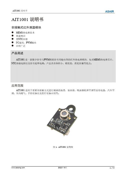
AIT1001说明书非接触式红外测温模块●MEMS热电堆技术●快速响应●带NTC补偿●I2C通讯,PWM输出●应用广泛产品简述AIT1001是一款数字信号与PWM模拟信号双输出型的红外热电堆模块,包含MEMS热电堆芯片、NTC热敏电阻以及信号处理电路。
产品具有体积小、精度高、质优价廉等优点。
应用范围AIT1001适用于需要非接触方式进行测温的场景,如冰箱、吸油烟机和空调等家用电器、汽车空调、室内暖气、手持设备以及医疗设备应用等。
图1.AIT1001实物图1.极限额定值表1.极限额定值2.性能参数及电气接口表2.模块性能参数表表3.电气接口说明注:上拉电阻的阻值推荐4.7kΩ。
AIT1001对应表3的电气接口如图2所示,其中端子规格为MX1.25-5PIN端子座。
图2.电气接口图3.产品尺寸图图3.产品尺寸图(单位:mm,公差:±0.3mm)4.通用寄存器表4.通用寄存器说明如需校准uValAdj或NtcAdj参数时,应将模块放置在与被测物体温度相同的环境中,根据如下条件进行校准:1、AIT1001模块输出的NTC温度应与环境温度相同,若偏差过大(>±0.5℃)可将修正值写入NtcAdj寄存器进行校准;2、热电堆电压uVal应在-15~+15µV内,若偏差过大可将修正值写入uValAdj寄存器进行校准。
发射率(Coef)是指被测物体表面辐射出的能量与相同温度的黑体辐射出的能量的比率。
不同的物体,其发射率亦有所不同,可根据实际使用需要进行修改。
5.I2C数字协议AIT1001遵循I2C总线规范,并需作为从机使用。
SCL为时钟输入线,SDA为串行数据输入/输出线。
表5.I2C通讯说明表6.I2C时序及CRC校验6.1读取模块数据的时序在一个I2C完整的Start-Stop读取模块数据通信中,每个寄存器数据后跟随一个对该寄存器数据的CRC校验字节,其CRC校验码字节的计算是对该寄存器数据字节进行CRC计算所得,如图4所示。
ER104中文资料
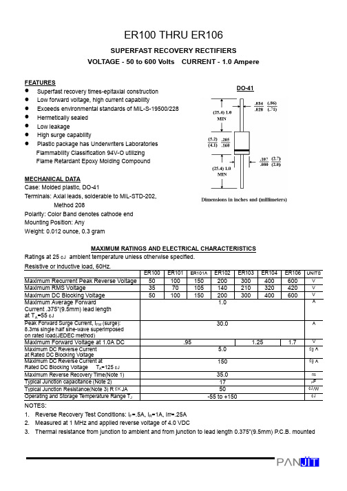
ER100 THRU ER106SUPERFAST RECOVERY RECTIFIERSVOLTAGE - 50 to 600 Volts CURRENT - 1.0 AmpereFEATURESl Superfast recovery times-epitaxial construction l Low forward voltage, high current capabilityl Exceeds environmental standards of MIL-S-19500/228l Hermetically sealed l Low leakagel High surge capabilityl Plastic package has Underwriters Laboratories Flammability Classification 94V-O utilizing Flame Retardant Epoxy Molding Compound MECHANICAL DA TACase: Molded plastic, DO-41Terminals: Axial leads, solderable to MIL-STD-202, Method 208Polarity: Color Band denotes cathode end Mounting Position: Any Weight: 0.012 ounce, 0.3 gramMAXIMUM RA TINGS AND ELECTRICAL CHARACTERISTICSRatings at 25¢J ambient temperature unless otherwise specified.Resistive or inductive load, 60Hz.ER100ER101ER101AER102ER103ER104ER106UNITS Maximum Recurrent Peak Reverse Voltage 50100150200300400600V Maximum RMS Voltage3570105140210320420V Maximum DC Blocking Voltage 50100150200300400600V Maximum Average ForwardCurrent .375"(9.5mm) lead length at T A =55¢J1.0APeak Forward Surge Current, I FM (surge):8.3ms single half sine-wave superimposed on rated load(JEDEC method)30.0AMaximum Forward Voltage at 1.0A DC.951.251.7V Maximum DC Reverse Current at Rated DC Blocking Voltage 5.0£g A Maximum DC Reverse Current atRated DC Blocking Voltage T A =125¢J 150£g A Maximum Reverse Recovery Time(Note 1)35.0nsTypical Junction capacitance (Note 2)17P FTypical Junction Resistance(Note 3) R £K JA 50¢J /W Operating and Storage T emperature Range T J-55 to +150¢JNOTES:1. Reverse Recovery T est Conditions: I F =.5A, I R =1A, Irr=.25A2. Measured at 1 MHz and applied reverse voltage of 4.0 VDC3. Thermal resistance from junction to ambient and from junction to lead length 0.375”(9.5mm) P .C.B. mountedDO-41RATING AND CHARACTERISTIC CURVES ER100 THRU ER106NOTE:1.Rise Time = 7ns max.Input Impedance = 1 megohm. 22pF 2.Rise Time = 10ns max. Source Impedance = 50 Ohms50 ns/cmFig. 1-REVERSE RECOVERY TIME CHARACTERISTIC ANDTEST CIRCUIT DIAGRAMFig. 2-MAXIMUM NON-REPEITIVESURGE CURRENTAMBIENT TEMPERATURE, ¢JFig. 3-MAXIMUM AVERAGE FORWARD CURRENT RATINGINSTANTANEOUS FORWARD VOLTAGE VOLTSFig. 4-FORWARD CURRENTDERATING CURVE% OF PIV, VOLTSREVERSE VOLTAGE, VOLTSFig. 5-TYPICAL REVERSE CHARACTERISTICSFig. 6-TYPICAL JUNCTIONCAPACITANCE。
TP1001中文资料_TP1001规格书_TP1001 PDF

PCB 布局
TP1001在进行PCB布局时,建议按以下规则进行:
走线
V1,V2,V3连接到开关电源的反馈网络,其走线要尽可能 的短;芯片的地线离开关电源的反馈网络的地线要尽可 能的短;同时走线要远离开关电源的干扰源。
当 USB 线缆断开时,D+的电压值被下拉电阻 RPDR_D+拉 低(见典型应用图)。一旦 D+的电压低于 VDAT_REF 时, TP1001 将导通开关 N5 从而将 D+和 D-短路并且关断开 关 N1~N4。 这时 TP1001 进入 USB 电池充电规范 1.2 版 兼容模式,电源默认输出 5V 电压值。RPDR_D+的建议取 值为 RPDR_D+=390kΩ。
Shenzhen TPOWER Semiconductor
TP1001 支持 QC2.0 快速充电协议的接口控制芯片
内部框图
应用说明
TP1001 是一款支持 QC2.0 快速充电协议的低成本接口 控制芯片。 TP1001 集成了所有必要的功能,可以将 QC2.0 功能添加到 AC/DC 适配器、 充电器和移动电源等 其他开关电源设备中,以实现对支持 QC2.0 协议的受电 设备的快速充电功能。 TP1001 支持 QC2.0 协议的整个输出电压范围,包括 A 类规范的输出电压范围(5V,9V,12V)和 B 类规范的输出电 压范围(5V,9V,12V,20V)。TP1001 可以自动检测出受电 设备为支持 QC2.0 协议或者为支持 USB 电池充电规范 1.2 版本,并且相应的启用输出电压调节功能。
Shenzhen TPOWER Semiconductor
TP1001 支持 QC2.0 快速充电协议的接口控制芯片
Endress+Hauser Proline Promag E 100 PROFINET 电磁流量计

Products Solutions Services操作手册Proline Promag E 100PROFINET电磁流量计BA01423D/06/ZH/01.1571316215自下列版本起生效01.00.zz (设备固件)•请将文档妥善保存在安全地方,便于操作或使用设备时查看。
•为了避免出现人员或装置危险,请仔细阅读“基本安全指南”章节,以及针对特定操作步骤的文档中的所有其他安全指南。
•制造商保留修改技术参数的权利,将不预先通知。
Endress+Hauser当地销售中心将为您提供最新文档信息和更新文档资料。
2Endress+Hauser目录Endress+Hauser3目录1文档信息 (5)1.1文档功能.............................51.2信息图标.............................51.2.1安全图标......................51.2.2电气图标......................51.2.3工具图标......................51.2.4特定信息图标...................51.2.5图中的图标.....................61.3文档资料.............................61.3.1标准文档资料...................61.3.2补充文档资料...................61.4注册商标.............................62基本安全指南 (8)2.1人员要求.............................82.2指定用途.............................82.3工作场所安全.........................92.4操作安全.............................92.5产品安全.............................92.6IT 安全..............................93产品描述 (10)3.1产品设计............................103.1.1PROFINET 型仪表 (10)4到货验收和产品标识 (11)4.1到货验收............................114.2产品标识............................114.2.1变送器铭牌....................124.2.2传感器铭牌....................134.2.3测量设备上的图标..............135储存和运输 (14)5.1储存条件............................145.2运输产品............................145.2.1测量设备,不带起吊吊环.........145.2.2测量设备,带起吊吊环...........145.2.3使用叉车的叉体运输.............155.3包装处置............................156安装 (15)6.1安装条件............................156.1.1安装位置.....................156.1.2环境条件和过程条件要求.........176.2安装测量设备........................196.2.1所需工具.....................196.2.2准备测量设备..................196.2.3安装传感器....................196.2.4旋转显示单元..................236.3安装后检查..........................237电气连接 (25)7.1连接条件............................257.1.1所需工具.....................257.1.2连接电缆要求..................257.1.3接线端子分配..................267.1.4针脚分配和仪表插头.............267.1.5准备测量设备..................277.2连接测量设备........................277.2.1连接变送器....................277.2.2确保电势平衡..................297.3特殊连接指南........................317.3.1连接实例.....................317.4硬件设置............................317.4.1设置设备名称..................317.5确保防护等级........................337.6连接后检查..........................338操作方式 (34)8.1操作方式概述........................348.2操作菜单的结构和功能.................358.2.1操作菜单结构..................358.2.2操作原理.....................368.3通过Web 浏览器访问操作菜单...........368.3.1功能范围.....................368.3.2前提.........................368.3.3建立连接.....................378.3.4退出.........................388.3.5用户界面.....................398.3.6关闭Web 服务器...............408.3.7退出.........................408.4通过调试工具访问操作菜单..............408.4.1连接调试工具..................408.4.2FieldCare .....................418.4.3DeviceCare ....................439系统集成 (44)9.1设备描述文件概述.....................449.1.1当前设备版本信息..............449.1.2调试工具.....................449.2设备描述文件(GSD)....................459.2.1设备描述文件(GSD)的文件名......459.3的循环数据传输......................459.3.1块说明.......................459.3.2块说明.......................459.3.3状态编码.....................519.3.4工厂设置.....................5110调试 (53)10.1功能检查............................5310.2识别PROFINET 网络中的设备............5310.3启动参数设置........................5310.4通过FieldCare 建立连接................5310.5设置操作语言........................53目录4Endress+Hauser10.6设置测量设备........................5310.6.1设置位号名称..................5410.6.2设置系统单位..................5410.6.3显示通信接口..................5510.6.4设置小流量切除................5610.6.5设置空管检测..................5810.7高级设置............................5910.7.1执行传感器调整................5910.7.2设置累加器....................5910.7.3执行高级显示设置..............6110.7.4执行电极清洗..................6310.8仿真...............................6410.9写保护设置,防止未经授权的访问........6510.9.1通过访问密码设置写保护.........6510.9.2通过写保护开关设置写保护.......6610.9.3通过启动参数设置设置写保护 (66)11操作 (67)11.1查看设备锁定状态.....................6711.2调整操作语言........................6711.3设置显示............................6711.4读取测量值..........................6711.4.1过程变量.....................6711.4.2累加器.......................6811.5使测量设备适应过程条件...............6911.6执行累加器复位......................6912诊断和故障排除 (71)12.1常规故障排除........................7112.2通过发光二极管标识诊断信息............7212.2.1变送器.......................7212.3Web 浏览器中的诊断信息...............7312.3.1诊断方式.....................7312.3.2查看补救信息..................7412.4FieldCare 中的诊断信息................7412.4.1诊断选项.....................7412.4.2查看补救信息..................7612.5调整诊断信息........................7612.5.1调整诊断响应..................7612.6诊断信息概述 ........................7912.6.1传感器诊断....................7912.6.2电子部件诊断..................8112.6.3配置诊断.....................8512.6.4进程诊断.....................8912.7待解决诊断事件......................9112.8诊断列表............................9212.9事件日志............................9212.9.1事件历史.....................9212.9.2筛选事件日志..................9312.9.3事件信息概述..................9312.10复位测量设备........................9412.10.1“设备复位” 参数的功能范围.......9412.11设备信息............................9512.12固件更新历史........................9613维护 (97)13.1维护任务............................9713.1.1外部清洗.....................9713.1.2内部清洗.....................9713.1.3更换密封圈....................9713.2测量和测试设备......................9713.3Endress+Hauser 服务..................9714修理 (98)14.1概述...............................9814.2备件...............................9814.3Endress+Hauser 服务..................9814.4返回...............................9814.5废弃...............................9814.5.1拆卸测量设备..................9814.5.2废弃测量设备..................9915附件 (100)15.1仪表类附件.........................10015.1.1变送器......................10015.1.2传感器......................10015.2服务类附件.........................10015.3系统组件...........................10116技术参数 (102)16.1应用..............................10216.2功能与系统设计.....................10216.3输入..............................10216.4输出..............................10316.5电源..............................10616.6性能参数...........................10716.7安装..............................10816.8环境条件...........................10816.9过程条件...........................10916.10机械结构...........................11016.11可操作性...........................11416.12证书和认证.........................11616.13应用软件包.........................11716.14附件..............................11716.15补充文档资料.......................118索引 (119)Proline Promag E 100 PROFINET文档信息1 文档信息1.1 文档功能《操作手册》提供设备在生命周期各个阶段内的所有信息:从产品标识、到货验收和储存,至安装、连接、操作和调试,以及故障排除、维护和废弃。
er100s-g焊丝标准

ER100S-G焊丝标准一、化学成分ER100S-G焊丝的化学成分应符合表1的规定。
表1 ER100S-G焊丝的化学成分(%)元素 C Mn Si S P Cr Ni Mo Ti含量≤0.12 ≤2.00 ≤0.60 ≤0.035 ≤0.035 ≤0.50 ≤0.50 ≤0.30 ≤0.30二、机械性能1. ER100S-G焊丝的抗拉强度应不低于表2的规定。
表2 ER100S-G焊丝的抗拉强度(MPa)规格φ1.2 φ1.6 φ2.0 φ2.4 φ3.2 φ4.0 φ5.1抗拉强度≥490 ≥590 ≥620 ≥660 ≥710 ≥750 ≥8002. ER100S-G焊丝的伸长率应不低于表3的规定。
表3 ER100S-G焊丝的伸长率(%)规格φ1.2 φ1.6 φ2.0 φ2.4 φ3.2 φ4.0 φ5.1伸长率≥22 ≥22 ≥22 ≥21 ≥20 ≥19 ≥19三、几何尺寸ER100S-G焊丝的几何尺寸应符合表4的规定。
表4 ER100S-G焊丝的几何尺寸(mm)规格φ1.2 φ1.6 φ2.0 φ2.4 φ3.2 φ4.0 φ5.1直径偏差±0.06 ±0.07 ±0.08 ±0.10 ±0.15 ±0.25 ±0.35长度偏差±5.0 ±6.0 ±8.0 ±10.0 ±13.0 ±16.0 ±20.0四、表面状态ER100S-G焊丝的表面应光滑、洁净,不得有裂纹、毛刺、凹坑、锈蚀及其他机械损伤等缺陷。
五、包装和标识ER100S-G焊丝应采用防潮包装,包装内应附有质量证明书。
每卷焊丝的标识应包括产品名称、规格、批号、净重等信息,以便于质量追溯和管理。
埃尔斯特FC1流量计算机操作维护操作规程
埃尔斯特FC1流量计算机操作维护操作规程文件编号:版本号:编制单位:批准人:发布日期:埃尔斯特FC1流量计算机操作维护操作规程1 范围本规程适用于由Elster生产的FC1型流量计算机的操作维护。
2 规范性引用文件GB/T 18603-2014 天然气计量系统技术要求3 术语和定义无4 一般要求4.1操作人员必须经过培训,了解设备基本操作;4.2操作人员必须持有计量交接员资格证;4.3监控工况流量,避免流量计分界流量以下情况下运行。
5 运行操作5.1 启动前的检查和准备5.1.1检查超声波流量计、温度变送器、压力变送器、流量计算机、色谱等设备在检定、标定有效期内。
5.1.2启动前检查流量计、温度变送器、压力变送器、色谱控制、上位机信号线均已正确接入流量计算机,接线端子牢固。
5.1.3开机启动前,检查并确保已接入正确的24VDC电源。
5.2 启动5.2.1合上流量计算机的电源开关,观察前端面板的各状态指示等状态。
绿灯常亮,显示器经数秒后显示制造单位徽标及名称,之后进入流量显示主界面,开机启动正常。
5.2.2流量计算机报警状态正常。
5.3 运行操作5.3.1 常用数据查看5.3.1.1开机主界面显示名称为常用数据。
此界面用于查看常用的数据。
包括:总累积量,小时累积量, 日累积量, 瞬时流量,压缩因子,温度,压力,气质组分等数据。
在正式运行前需对流量计算机进行初步校验,这时可通过上位机检查通讯情况,确保数据通讯链路畅通。
5.4 运行调整5.4.1查看气体组分参数是否正常,且是最新数据。
或按照最新组分分析报告手动录入气体组分值。
5.4.1.1主界面(常用数据)。
5.4.1.2按右键至设置菜单。
5.4.1.3选定Stream1菜单,按进入查看组分数据或录入固定组分。
5.4.1.4录入完成后,点击确认。
录入完成后查看组分数据5.5 运行中的检查5.5.1检查流量计算机中流量、压力、温度数据显示是否正常。
在Stream1菜单中直接对压力、温度进行检查。
ER1000FCT – ER1006FCT
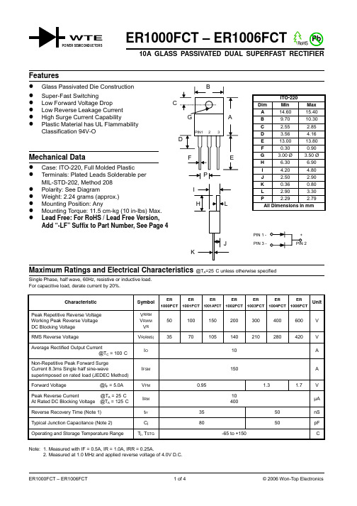
ER1000FCT – ER1006FCT10A GLASS PASSIVATED DUAL SUPERFAST RECTIFIERSingle Phase, half wave, 60Hz, resistive or inductive load.For capacitive load, derate current by 20%.CharacteristicSymbol ER 1000FCT ER 1001FCT ER 1001AFCT ER 1002FCT ER 1003FCT ER 1004FCT ER 1006FCTUnitPeak Repetitive Reverse Voltage Working Peak Reverse Voltage DC Blocking Voltage V RRM V RWM V R 50100150200300400600V RMS Reverse VoltageV R(RMS)3570105140210280420V Average Rectified Output Current@T C = 100°C I O10ANon-Repetitive Peak Forward Surge Current 8.3ms Single half sine-wavesuperimposed on rated load (JEDEC Method)I FSM 150A Forward Voltage @I F = 5.0A V FM 0.951.31.7V Peak Reverse Current @T A = 25°C At Rated DC Blocking Voltage @T A = 125°C I RM 10400µA Reverse Recovery Time (Note 1)t rr3550nSTypical Junction Capacitance (Note 2) C j 80 50 pF Operating and Storage Temperature RangeT j , T STG-65 to +150°CNote: 1. Measured with IF = 0.5A, IR = 1.0A, IRR = 0.25A.2. Measured at 1.0 MHz and applied reverse voltage of 4.0V D.C.WTE3060900120150180110100I ,P E A K F O R W A R D S U R G E C U R R E N T (A )F S M NUMBER OF CYCLES AT 60HzFig.3Max Non-Repetitive SurgeCurrent10100400V,REVERSE VOLTAGE (V)Fig.4Typical Junction CapacitanceR C ,C A P A C I T A N C E (p F )j 0246810050100150I ,A V E R A G E F O R W A R D C U R R E N T (A )(A V )T ,CASE TEMPERATURE (C)Fig.1Forward Current Derating CurveC °0.11.0101000.20.61.01.4I ,I N S T A N T A N E O U S F O R W A R D C U R R E N T (A )F V ,INSTANTANEOUS FORWARD VOLTAGE (V)Fig.2Typical Forward CharacteristicsFMARKING INFORMATIONRECOMMENDED SCREW MOUNTING ARRANGEMENTORDERING INFORMATIONProduct No.Package TypeShipping QuantityER1000FCT ITO-22050 Units/Tube ER1001FCT ITO-22050 Units/Tube ER1001AFCT ITO-22050 Units/Tube ER1002FCT ITO-22050 Units/Tube ER1003FCT ITO-22050 Units/Tube ER1004FCT ITO-22050 Units/Tube ER1006FCTITO-22050 Units/Tube1. Shipping quantity given is for minimum packing quantity only. For minimumorder quantity, please consult the Sales Department.2.To order RoHS / Lead Free version (with Lead Free finish), add “-LF” suffix to part number above. For example, ER1000FCT-LF .Won-Top Electronics Co., Ltd (WTE) has checked all information carefully and believes it to be correct and accurate. However, WTE cannot assume any responsibility for inaccuracies. Furthermore, this information does not give the purchaser of semiconductor devices any license under patent rights to manufacturer. WTE reserves the right to change any or all information herein without further notice.WARNING : DO NOT USE IN LIFE SUPPORT EQUIPMENT. WTE power semiconductor products are not authorized for use as critical components in life support devices or systems without the express written approval.We power your everyday.Won-Top Electronics Co., Ltd.No. 44 Yu Kang North 3rd Road, Chine Chen Dist., Kaohsiung, Taiwan Phone: 886-7-822-5408 or 886-7-822-5410Fax: 886-7-822-5417Email: sales@Internet: 。
传输专业常用仪表

6
一、EST-125功能键
C
D
No Clk/ No Sig
E
X.50Fr/ MultiFr Pattern Multi Frame
OK
Option
Frame
Frame
CRC Error FAS/ Char
Bit
Sync Loss Alarm/ Error Batt AIS Sync Loss Slip All 1
S5
S6
1. Timer(定时器设置):若选择OFF,表示不使用定时器功能;若选择 ON,则可 使用*Timer Menu*菜单进行手动启动或延时启动一测试的可编程时长。在 *Timer Menu*中,<Start time>启动时间可设置为MANUAL(手动启动测试), DELAYED(延时启动测试)用于选择一测试的延时启动的时间和日期。 <Duration>( 时长 )可按测试需要设置时长,最多可设置成60小时。
25
五、测试时可能遇到的问题三
仪表无法正常使用外部电源进行充电。仪表被关闭并且接到外部电源 上,如果此仪表上的外部电源LED被点亮而电源LED没有被点亮,则怀 疑充电器保险丝被烧断。此时无法对仪表进行充电,必须更换充电器保 险丝。 当仪表需要接入或断开外部电源时,确认仪表处于关闭状态!否则 很容易导致充电器保险烧断,从而无法使用外部电源对仪表进行充电! 当进行充电时,关闭此仪表。在大约14小时之后,将会充电完毕
Code/ Par
F F
S1 S2 S3 S4 S5 S6
G H
MAIN MENU
L
1 4
2 5 8 0
3 6 9 #
S7
F
小巨人车床主要参数
以下报警说明伺服控制回路发生错误PC显示LED显示名称详细S01 0011 S1 11 PCB错误1 放大器内的PCB发生错误S01 0013 S1 13 软件处理超时,时钟错误放大器内的时钟发生错误电机类型错误编码器初始通讯错误S01 0016 S1 16 电机类型、编码器类型错误编码器CPU错误伺服放大器中的A/D转换器发生错误S01 0017 S1 17 PCB错误1(A/D转换初始错误)S01 0025 S1 25 绝对位置丢失编码器内部绝对位置数据发生错误S01 0034 S1 34 CRC错误与NC的通讯发生错误S01 0036 S1 36 通讯超时,NC down 与NC的通讯被中断S01 0037 S01 0038 S01 0039 S1 37 参数错误S1 38 frame错误S1 39 INFO错误参数设定值错误与NC的通讯发生错误NC传输了未被定义的数据S02 0011 S2 11 PCB错误1 放大器内的PCB发生错误S02 0013 S02 0015 S2 13 软件处理超时,时钟错误S2 15 EEROM错误放大器内的时钟发生错误伺服放大器中的EEROM发生写入错误伺服放大器中的A/D转换器发生错误S02 0017 S2 17 PCB错误1(A/D转换错误)S02 0018 S2 18 PCB错误(LSI错误)伺服放大器中的LSI发生错误S02 0020 S2 20 编码器故障伺服放大器与编码器之间的通讯发生错误电源接通时,检测到接地输出错误S02 0024 S2 24 接地问题S03 0010 S3 10 电压不足电源电压为160V或更低内部再生电阻或外部再生选项超过再生容许值S03 0030 S3 30 再生错误再生晶体管错误S03 0031 S3 31 超速电机速度超过允许的瞬间速度S03 0032 S3 32 过电流电流超过伺服放大器容许值S03 0033 S3 33 过电压伺服放大器中的转换器电压达到400V或更高S03 0033 S3 33 过电压到400V或更高S03 0046 S3 46 电机过热运行方式使得电机连续过载S03 0050 S3 50 过载1 伺服放大器或伺服过载保护功能启动。
罗斯杰格器高频技术有限公司 RPC-TNC 校准套件全版本 06CK001-150说明书

Picture shows similar calibration kitDevice Part number Quantity Calibration Option Open circuit plug 06S12L-000S3 1 FCOpen circuit jack 06K12L-000S3 1 FCShort circuit plug 06S12S-000S3 1 FCShort circuit jack 06K12S-000S3 1 FC Calibration load plug 06S150-C10S3 1 FC Calibration load jack 06K150-C10S3 1 FC Calibration adaptor plug/plug 06S121-S20S3 1 FC Calibration adaptor jack/jack 06K121-K20S3 1 FC Calibration adaptor05S106-S20S3 1 FCRPC-N plug / RPC-TNC plugCalibration adaptor05K106-K20S3 1 FCRPC-N jack / RPC-TNC jackCombi wrench 53W011-000 1 -Torque wrench 06W021-000 1 FCD i e s e s D o k u m e n t i s t u r h e b e r r e c h t l i c h g e s c h üt z t ● T h i s d o c u m e n t i s p r o t e c t e d b y c o p y r i g h t ● R o s e n b e r g e r H o c h f r e q u e n z t e c h n i k G m b H & C o . K G6.1DocumentationThis kit is delivered with • USB-StickStandard Definitions as data files for Vector Network Anaylzer Families PNA (Keysight/Agilent) and ZVA (Rohde&Schwarz). Calibration Certificate as PDF-file. • Standard Definitions CardsPrinted Standard Definitions that can be used on nearly all Vector Network Analyzers. • Kit Info CardHandling precautions and information for installing Standard Definitions on a Vector Network Analyzer. • Calibration CertificateDetails see “Declaration of calibration options” • Operating ManualElectrical specificationsThis specification covers electrical key values for the main calibration standards of the calibration kit. Specific datasheets are available for each component among the part number.Calibration standardFrequencyParameterSpecificationOpensb(plug and jack)DC > 4 GHz > 8 GHz to to to ≤ 4 GHz ≤ 8 GHz ≤ 18 GHz Error fromNominal Phase ≤ 3.5° ≤ 5.0° ≤ 8.0° Shortsb(plug and jack)DC > 4 GHz > 8 GHz to to to ≤ 4 GHz ≤ 8 GHz ≤ 18 GHz Error fromNominal Phase≤ 1.0° ≤ 3.5° ≤ 7.0° Calibration loads (plug and jack)DC > 4 GHz to to ≤ 4 GHz ≤ 18 GHz Return Loss≥ 35 dB ≥ 25 dB Calibration adaptors (plug/plug and jack/jack) DC > 4 GHz to to ≤ 4 GHz ≤ 18 GHz Return Loss≥ 30 dB ≥ 20 dB Calibration adaptors RPC-N to RPC-TNC (plug/plug and jack/jack)DC > 4 GHz to to ≤ 4 GHz ≤ 18 GHzReturn Loss≥ 30 dB ≥ 20 dBb.The specifications for opens and shorts are given as allowed deviation from nominal model as defined in calibration certificate included with your kit.D i e s e s D o k u m e n t i s t u r h e b e r r e c h t l i c h g e s c h üt z t ● T h i s d o c u m e n t i s p r o t e c t e d b y c o p y r i g h t ● R o s e n b e r g e r H o c h f r e q u e n z t e c h n i k G m b H & C o . K G6.1Declaration of calibration optionsFactory CalibrationStandard delivery for this kit includes a Factory Calibration. The Calibration Certificate issued reportsindividual calibration results, traceable to Rosenberger standards , national / international standards are not available. Model based standard definitions of the calibration standards are reported in Agilent/Keysight, Rohde & Schwarz and Anritsu compatible VNA format.Accredited Calibration Not available.For further, more detailed information see application note AN001 on the Rosenberger homepage.Calibration intervalRecommendation 12 monthsRecommended accessories- Rosenberger Test Port Adaptor- Rosenberger VNA Test cable kit and Microwave Cable AssembliesFor further, more detailed information please visit our homepage .Draft Date Approved Date Rev. Engineering change numberName Date While the information has been carefully compiled to the best of our knowledge, nothing is intended as representation or warranty on our part and no statement herein shall be construed as recommendation to infringe existing patents. In the effort to improve our products, we reserve the right to make changes judged to be necessary.。
er1j二极管参数

ER1J超快恢复二极管的主要参数包括:
1.最大正向电压(Vrmax):二极管能够承受的最大正向电压。
超过该电压会导致二极管破坏。
2.最大反向电压(Vrmin):二极管能够承受的最大反向电压。
超过该电压会导致二极管破坏。
3.最大正向电流(Ifmax):二极管能够承受的最大正向电流。
超过该电流会导致二极管破坏。
4.最大反向电流(Irmax):二极管能够承受的最大反向电流。
超过该电流会导致二极管破坏。
此外,ER1J超快恢复二极管还有以下参数:
1.反向恢复时间(trr):从正向导通状态转换到反向截止状态所需的时间。
2.正向压降(Vf):在规定电流下的正向电压降。
以上信息仅供参考,如有需要,建议您查阅相关文献或咨询专业人士。
MultiRanger 100,200 使用手册说明书

使用手册 ·2005年4月安全指导:须注意警告提示以确保人身安全,保护产品及相关设备不受损坏。
这些警告提示均附带警告级别说明。
资质人员:本设备/系统须根据此手册进行安装和运行。
根据已有安全惯例和标准,只有具备资质的人员有权进行安装和操作此设备。
版权归西门子(中国)有限公司所有 免责申明装订版和电子版中均有此文档。
我们鼓励用户购买有授权的装订手册或者查看西门子(中国)有限公司设计和授权的电子版手册。
西门子(中国)有限公司对装订手册或电子版部分或全部内容的拷贝一律不负任何责任虽然我们对手册内容是否与仪表描述一致进行了核对,但仍可能存在变动。
这样我们不能确保完全一致。
手册内容会被有序的核查并纠正,勘误表登录在后续版本里。
我们欢迎用户提出各种改进建议。
技术数据可能有变动z 要查看西门子过程仪表手册,请进入/pi警告:此产品只有在正确运输、储存、安装、装配、操作及维护的情况下才能正确和安全的工作。
注意:请根据说明书使用本产品。
目录MultiRanger 100,200 (1)MultiRanger 100 (1)MultiRanger 200 (1)本手册 (1)手册符号 (2)配置举例 (2)规格 (3)安装 (8)安装 (8)安装场所 (9)安装说明 (9)墙装 (9)通过导管走线 (10)嵌板安装 (11)盘装 (12)MultiRanger母板 (13)安装电池 (13)安装SmartLinx 卡 (14)可选择设备 (14)接线 (15)端子板 (16)电缆 (16)探头 (17)继电器 (17)温度传感器 (18)mA 输入[MR 200] (18)mA 输出 (18)物位系统同步 (19)电源 (19)数字通信 (20)RS-232 串行连接 (20)RS-485串行连接 (20)离散输入 (20)MultiRanger 的运行 (21)运行模式 (21)运行模式中的读数 (22)状态参数 (23)显示的控制 (24)调整主要读数以适合四位LCD (24)辅助读数 (24)多种读数[仅MR200] (25)编程模式 (26)开始编程模式 (26)手操器 (26)手操器按键 (27)Dolphin Plus (28)Dolphin Plus 工具栏按钮 (29)SIMATIC 过程设备管理器(PDM) (30)设备描述 (30)激活MultiRanger (31)改变参数 (31)安全 (32)采用单位或百分比(%) (32)参数类型 (32)显示读数 (34)改变参数(Dolphin Plus) (34)参数索引 (35)主索引和二级索引 (36)主索引 (36)二级索引: (36)开始测量 (37)单点模式 (37)平均值或差值[仅MR200] (38)双点模式 (38)平均值或差值[仅MR200] (39)测量条件 (39)响应速度 (39)尺寸[仅MR200] (39)失效状态保持 (39)继电器 (40)概括介绍 (40)继电器功能 (40)报警 (40)泵 (41)各式混合 (41)继电器状态—非运行模式 (42)继电器状态 (42)继电器相关参数 (42)继电器配线测试 (43)继电器激活 (43)继电器失效状态保持 (44)预设置应用 (45)优先的物位备份 (46)优先的物位备份的参数 (46)离散输入 (47)离散输入配线 (47)离散输入逻辑编程 (47)mA I/O (48)mA输入[MR 200] (48)mA输出 (48)体积[MR 200] (50)读数 (50)容器形状和尺寸 (50)特性表[MR 200] (51)例表 (51)只用于MultiRanger 200 (52)报警 (53)物位 (53)设置简单的物位报警 (54)速度[MR 200] (54)范围内/范围外报警[MR 200] (55)电缆故障 (55)温度[MR 200] (55)回波丢失(LOE) (56)泵的控制 (57)设置泵抽水参数组 (57)设置泵抽水(入蓄水池)参数组 (58)其它泵控制算法 (60)设置继电器为可变的任务接力模式[MR 200] (60)设置继电器实现固定的任务协助模式 (60)设置继电器实现固定的任务接力模式[MR 200] (61)设置继电器为可变的任务工作模式[MR 200] (61)设置继电器为先入先出(FIFO)协助模式[MR 200] (62)可选择的泵控制 (62)由物位变化率启动泵[MR 200] (62)根据工作比率使泵轮流工作[MR 200] (63)累计泵的抽取体积[MR 200] (64)设置独立的失效状态保持控制 (64)设置一个泵进行运转[MR 200] (65)设置泵的启动延迟[MR 200] (65)减轻墙壁附着[MR 200] (65)对泵分组[MR 200] (66)设置一个奔流阀[MR 200] (67)通过通信控制继电器 (67)跟踪泵的使用 (67)格栅控制[MR 200] (68)设置对隔栅的控制 (68)设置常用参数 (69)设置继电器1(操作隔栅) (69)设置继电器2到4(物位报警) (69)外部累加器和流体取样器[MR 200] (70)继电器触点 (70)累加器 (70)流体取样器 (71)基于体积和时间 (71)明渠监测(OCM)[MR 200] (72)常用参数 (72)设置水头零位 (73)设置累加体积 (74)MultiRanger 200支持的应用 (74)BS-3680 / ISO 1438/1 薄金属板V型切口堰 (74)BS-3680 / ISO 4359 矩形槽 (75)Palmer Bowlus 槽 (76)H型槽 (77)带有指数流量的PMD (78)适用的堰外形 (78)不适用的堰外形 (79)Parshall 槽 (79)Leopold Lagco 槽 (80)收喉槽 (81)通用计算支持 (82)典型流量特性 (83)槽示例 (83)堰示例 (83)测试配置 (85)仿真 (85)仿真一个简单的测量 (85)对一个物位周期进行仿真 (85)校验体积特性描述[MR 200] (86)校验OCM流量特性描述[MR 200] (86)I/O校验 (87)应用测试 (87)MultiRanger 通信 (89)MultiRanger 通信系统 (89)可选择的SmartLinx卡 (89)通信系统 (90)通信端口 (90)Modbus (91)SmartLinx (91)Dolphin Plus (91)接线指导 (92)端口1和2 (92)端口1和2:RS-232 RJ-11插孔和RS-485位置 (92)端口1:RS-232 RJ-11插孔 (93)端口2:RS-485 (93)配置通信接口(参数) (94)Modbus 寄存器规约 (97)字顺序(R40,062) (98)规约ID(R40,063) (98)产品ID(R40,064) (99)测量点数据(R41,010-R41,031) (99)累加值(R41,040-R41,043) (99)输入/输出(R41,070-R41,143) (100)离散输入(R41,070) (100)继电器输出(R41,080) (100)mA 输入(R14,090)[MR 200] (100)mA 输出(R41,110-41,111) (100)泵控制(R41,400-R41,474) (100)泵开设定点(R41,420-R41,425) (100)泵关设定点(R41,430-R41,435) (101)泵抽取体积(R41,440-R41,443)[MR 200] (101)泵工作时间(R41,450-R41,461) (101)泵启动次数(R41,470-R41,475) (101)参数读取(R43,998-R46,999) (102)参数索引 (102)索引参数存取区域 (102)读参数 (103)普通索引方法(P782=0) (103)参数特定索引方法(P782=1) (104)写参数 (104)普通索引方法(P782=0) (104)参数特定索引方法(P782=1) (104)格式字(R46,000到R46,999) (105)通用索引方法(P782=0) (105)参数特定索引方法(P782=1) (105)格式寄存器 (105)数据类型 (107)数字型数值 (107)位型数值 (107)无符号双精度整数(UINT32) (107)分离型数据 (108)文本信息 (109)继电器功能代码(P111) (110)Modbus响应 (112)错误处理 (112)通信故障诊断 (114)常规检查 (114)特殊检查 (114)通信附录A:单一参数读取(SPA) (115)图表 (115)读参数 (115)写参数 (116)格式寄存器 (116)错误代码 (117)参数参考 (119)MultiRanger 100 和 MultiRanger 200 (119)重要提示 (119)快速启动(P001到P007) (121)DPD和DPA编程[MR 200] (122)体积(P050到P055)[MR 200] (125)显示和读数(P060 到 P062) (129)物位跨跃备份 (131)失效状态保持参数(P070到P072) (133)继电器(P100到P129) (134)MutiRanger 200 (136)泵设定点修正(P121和P122)[MR 200] (141)独立继电器失效状态保持(P129) (142)高级泵控制修正(P130到P137)[MR 200] (143)奔流系统(P170到P173)[MR 200] (146)mA输出(P200到P219) (148)独立mA设定点(P210和P211) (150)mA输出限制(P212和P213) (151)mA输出修正(P214和P215) (152)mA输出实效状态保持(P219)[MR200] (153)mA输入(P250到P260)[MR200] (153)离散输入函数(P270到P275) (155)标准数据记录(P300到P321) (156)记录温度 (P300到P303) (156)记录读数(P304和P305) (158)泵记录(P309到P312) (158)流量记录(P320和P321)[MR200] (159)LCD累加器(P322和P323)[MR200] (160)波形记录(P330到P337) (161)自动记录ON/OFF设定点(P334到 P337) (164)装置记录(P340到P342) (166)明渠监控(P600到P621)[MR200] (167)样本指数 (169)泵抽取体积累加器(P622)[MR200] (176)累加器(P630到P645)[MR200] (177)量程标定参数(P650至P654) (180)温度补偿参数(P660至P664) (183)速度参数(P700至P708) (185)测量检验参数(P710到 P713) (189)探头扫描参数(P726至729) (192)显示参数(P730至P733) (193)SmartLinx 保留参数(P750到P769) (196)通信(P770到P782) (196)SmartLinx 硬件测试(P790到P795) (199)回波处理参数(P800到P807) (201)先进的回波处理(P815到P825) (217)高级TVT调整(P830到P835) (217)声波发射调整高级设置(P840-P852) (217)测试参数(P900到P913) (217)测量参数(P920到P927) (221)主复位(P999) (224)常用附录A:索引类型 (225)索引类型 (225)常用索引B — 技术参考 (226)传输脉冲 (226)回波处理 (226)TVT(时间变化阈值)曲线 (227)自动虚假回波抑制 (227)距离计算 (228)声速 (228)扫描 (229)体积计算[MR200] (229)通用,曲线[MR200] (230)流量计算 (230)通用,线形[MR200] (231)通用,曲线[MR200] (231)最大过程速度 (232)常用附录C:故障诊断 (233)常用故障表 (233)噪声问题 (234)确定噪声源 (235)非探头噪声源 (235)常见接线问题 (236)降低电噪声 (236)降低声噪声 (236)测量故障 (237)闪烁的LOE显示 (237)调整探头瞄准 (237)增加失效状态保持定时器值 (238)安装一个波束较窄的探头 (238)使用Dolphin Plus调试回波 (238)固定读数 (238)声束方向上的障碍物 (238)管嘴安装 (238)设置MultiRanger来忽略虚假回波 (239)错误读数 (239)错误读数的类型 (239)液体飞溅 (239)调整回波算法 (239)探头振铃 (240)设备维修和免责申明 (241)常用附录D:泵控制参考 (242)泵控制选项 (242)泵组 (242)速率对泵控制[MR200] (242)泵控制算法 (243)固定的任务协助模式(P110=50) (243)固定的任务接力模式(P111=51)[MR200] (244)可变的任务协助模式(P111=52) (244)可变的任务接力模式(P111=53)[MR200] (245)工作比率式的任务协助模式(P111=54)[MR200] (246)工作比率式的任务接力模式(P111=55)[MR200] (247)先入先出(FIFO)(P111=56)[MR200] (247)速率对泵控制(P121)[MR200] (247)其他泵控制[MR200] (247)常用附录E:更新软件 (249)更新软件 (249)常用附录F:升级 (250)安装一个MultiRanger100/200 (250)连接探头 (250)同轴探头扩展 (250)用RG62同轴扩展电缆连接探头 (251)MultiRanger Plus 到MultiRanger100/200参数 (252)常见附录G:Class1,Div2应用的导管进入 (253)MultiRanger 100和200MultiRanger 有两种类型可选,MultiRanger 100和MultiRanger 200,它们经过设计能满足各种应用。
