Xperia Play 拆机
索尼 用户指南 Xperia XA1 Plus G3421 G3423 G3412 G3416 G3

用戶指南Xperia XA1 Plus內容開始使用 (6)關於本用戶指南 (6)概覽 (7)組裝–單SIM卡 (8)組裝–雙SIM卡 (9)屏幕保護 (9)首次啟動裝置 (9)為什麼我需要Google帳戶? (10)裝置安全性 (11)確保您的裝置受到保護 (11)屏幕上鎖 (11)將裝置自動解鎖 (12)指紋管理員 (12)SIM卡保護 (13)使用多張SIM卡 (13)找出您裝置的IMEI號碼 (14)尋找、上鎖或清除遺失的裝置 (15)使用定位服務 (15)了解基本功能 (17)使用輕觸螢幕 (17)啟動和關閉屏幕 (19)智能背光控制 (19)主屏幕 (19)應用程式畫面 (22)可輕鬆執行動作的捷徑 (23)瀏覽應用程式 (23)外掛件 (25)捷徑和資料夾 (25)背景與主題 (26)擷取螢幕截圖 (27)通知 (27)狀態列中的圖示 (29)應用程式概覽 (31)電池及維護 (33)為裝置充電 (33)電池及電量管理 (34)更新您的裝置 (35)使用電腦進行維護 (37)儲存空間與記憶體 (38)備份及還原內容 (39)下載應用程式 (42)從Google Play下載應用程式 (42)從其他來源下載應用程式 (42)網際網路和網路 (43)瀏覽網絡 (43)互聯網和MMS設定 (43)Wi-Fi (43)分享流動數據連線 (45)控制數據用量 (47)選擇用於處理數據流量的SIM卡 (47)選擇流動網絡 (48)同步處理裝置上的資料 (49)與網上帳戶同步 (49)與Microsoft Exchange ActiveSync同步化 (49)基本設定 (50)存取設定 (50)音量、震動和聲音 (50)透過請勿騒擾將裝置設為靜音 (51)屏幕設定 (52)螢幕釘選 (52)應用程式設定 (53)重新設定您的應用程式 (54)語言設定 (54)日期和時間 (55)增強音效輸出 (55)多用戶帳號 (55)輸入文字 (58)屏幕鍵盤 (58)編輯文字 (59)自動填滿 (59)通話 (60)撥打電話 (60)接聽來電 (61)轉接來電 (62)封鎖號碼 (62)聯絡人 (64)新增及編輯聯絡人 (64)聯絡人分組 (65)傳送通訊錄 (65)備份通訊錄 (66)短訊和聊天 (67)讀取和傳送訊息 (67)訊息功能設定 (68)視像聊天 (68)設定電子郵件 (69)音樂和FM收音機 (70)將音樂傳送至您的裝置 (70)聆聽音樂 (70)聆聽收音機 (72)相機 (74)了解您的相機 (74)曝光、顏色與光線條件 (77)設定正確的焦點 (79)人像、自拍與微笑臉孔 (80)移動物體 (81)使用相機應用程式 (81)解像度與記憶體 (82)診斷您的相機 (84)其他相機設定 (84)相簿中的相片和影片 (86)查看相片和影片 (86)相簿主屏幕目錄 (87)分享及管理相片和影片 (88)隱藏相片和影片 (88)連接 (90)以無線方式,將裝置的屏幕鏡射到電視上 (90)將您的裝置連接至USB配件 (90)NFC(近距離通訊) (90)Bluetooth無線技術 (92)智能應用程式及功能可幫您節省時間 (95)Google Feed (95)將您的裝置當成錢包來使用 (95)Xperia Actions (95)時鐘與行事曆 (97)行事曆 (97)時鐘 (97)協助工具 (100)放大 (100)字型大小 (100)顯示大小 (100)色彩校正 (100)TalkBack (100)單聲道音訊 (101)Switch Access (101)支援與法律規範 (102)支援應用程式 (102)重新開始、開始設定與維修 (102)保養、SAR及使用指引 (103)法律資訊 (103)開始使用關於本用戶指南這是Android™ 8.0軟件版本的Xperia XA1 Plus用戶指南。
索尼爱立信_Xperia_Neo_MT15i_拆机图文教程

索尼爱立信Xperia Neo MT15i 拆机图文教程索尼爱立信Xperia Neo MT15i 怎么无损拆机,相信这个众多手机发烧友的难题。
这篇拆机图及其详细的介绍索尼爱立信Xperia Neo MT15i 拆机过程中每一个步骤和需要注意的地方。
当然自行拆机有风险,三思而后行。
1.一套白色neo外壳,袖珍十字螺丝刀、直板螺丝刀各一把,眼镜布一块腹有诗书气自华2.取出6颗银色螺丝钉腹有诗书气自华3.抠开排线盖腹有诗书气自华4.拔掉排线腹有诗书气自华5.用三角片小心撬开两个银边,很不好弄得,小心点就行腹有诗书气自华腹有诗书气自华腹有诗书气自华6.外屏玻璃、上方排线小心按下来腹有诗书气自华腹有诗书气自华腹有诗书气自华腹有诗书气自华7.不太清楚这是什么,应该是屏蔽用的,我也给接下来了,贴在新壳上8.装机步骤请看。
出师表两汉:诸葛亮先帝创业未半而中道崩殂,今天下三分,益州疲弊,此诚危急存亡之秋也。
然侍卫之臣不懈于内,忠志之士忘身于外者,盖追先帝之殊遇,欲报之于陛下也。
诚宜开张圣听,以光先帝遗德,恢弘志士之气,不宜妄自菲薄,引喻失义,以塞忠谏之路也。
宫中府中,俱为一体;陟罚臧否,不宜异同。
若有作奸犯科及为忠善者,宜付有司论其刑赏,以昭陛下平明之理;不宜偏私,使内外异法也。
侍中、侍郎郭攸之、费祎、董允等,此皆良实,志虑忠纯,是以先帝简拔以遗陛下:愚以为宫中之事,事无大小,悉以咨之,然后施行,必能裨补阙漏,有所广益。
将军向宠,性行淑均,晓畅军事,试用于昔日,先帝称之曰“能”,是以众议举宠为督:愚以为营中之事,悉以咨之,必能使行阵和睦,优劣得所。
亲贤臣,远小人,此先汉所以兴隆也;亲小人,远贤臣,此后汉所以倾颓也。
先帝在时,每与臣论此事,未尝不叹息痛恨于桓、灵也。
侍中、尚书、长史、参军,此悉贞良死节之臣,愿陛下亲之、信之,则汉室之隆,可计日而待也。
臣本布衣,躬耕于南阳,苟全性命于乱世,不求闻达于诸侯。
先帝不以臣卑鄙,猥自枉屈,三顾臣于草庐之中,咨臣以当世之事,由是感激,遂许先帝以驱驰。
强悍!图解索尼XPERIA X10拆机实录(中英文双语)
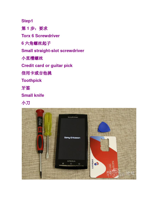
Step1第1步:要求Torx 6 Screwdriver6六角螺丝起子Small straight-slot screwdriver 小直槽螺丝Credit card or guitar pick信用卡或吉他挑Toothpick牙签Small knife小刀Step 2: Remove peripheral components步骤2:删除外围元件Remove all of the loose parts like the battery, si m card and memory card.删除,如电池,SIM卡和内存卡上的松散各地。
Step 3: Unscrewing第3步:螺牙Take out the 8 screws from the handset, keep th em in a safe place to avoid loosing any of them. 从手机取出8个螺丝,在一个安全的地方,使他们避免失去任何人。
Step 4: Remove lower support第4步:删除较低的支持Remove the lower part of the phone that has sm all connectors to the PCB and is half-glued to th e back cover.删除的手机已连接到PCB小,是半粘在后盖下部。
Use a small knife to pierce once under both side s of the handset.用小刀刺穿根据双方的手机一次。
You should now be able to lift it open with your own finger nails.您现在应该可以解除它打开自己的指甲。
Step 5: Create a gap between covers第五步:创建一个涵盖差距Starting at the top, use a guitar pick to create a small gap between the back and front covers.开始在顶部,使用吉他之间创建一个选择的背部和前的小差距封面。
索爱K810i官方拆机
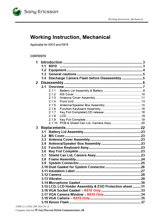
Working Instruction, MechanicalWorking Instruction, MechanicalApplicable for K810 and K818CONTENTS1Introduction (3)1.1K810 (3)1.2Equipment (4)1.3General cautions (5)1.4Discharge Camera Flash before Disassembly (5)2Disassembly (6)2.1Overview (7)2.1.1Battery Lid Assembly & Battery (8)2.1.2MS Cover (10)2.1.3Antenna Cover Assembly (11)2.1.4Front Unit (13)2.1.5Antenna/Speaker Box Assembly (14)2.1.6Function Keyboard Assembly (15)2.1.7Key Foil Complete/LCD release (16)2.1.8LCD (18)2.1.9Key Foil Complete (19)2.1.10PCB & Shield Can Lid, Camera Assy (20)3Replacements (22)3.1Battery Lid Assembly (23)3.2MS Cover (23)3.3Antenna Cover Assembly (23)3.4Antenna/Speaker Box Assembly (23)3.5Function Keyboard Assy (23)3.6Key Foil Complete (23)3.7Shield Can Lid, Camera Assy (23)3.8Frame Assembly (24)3.9System Connector (25)3.10Dust Gasket for System Connector (26)3.11Insulation Label (27)3.12Camera (28)3.13Vibrator (29)3.14Microphone Gasket (30)3.15LCD, LCD Holder Assembly & ESD Protection sheet (31)3.16VGA Socket Gasket – K810 Only (33)3.17VGA Camera Window – K810 Only (34)3.18VGA Camera – K810 Only (35)3.19Xenon Flash (37)Working Instruction, Mechanical3.20Numeric Keyboard (39)3.21Camera Key (40)3.22Ground Connectors (41)3.23Ear Speaker (42)3.24Front Assy (43)3.25Ear Speaker Gasket (44)3.26A/B Keys (45)3.27Loudspeaker Gasket (46)3.28Music Player Key (47)3.29Volume Key (48)3.30On/Off Key (49)3.31Handstrap Plate (50)3.32Liquid Indicator (51)3.33KRH Label (52)3.34Plug (External Antenna) (53)3.35Tape (holder capacitor) (54)4Reassembly (55)4.1Overview (56)4.1.1PCB & Shield Can Lid, Camera Assy (57)4.1.2Key Foil Complete (60)4.1.3LCD (61)4.1.4LCD/Key Foil Complete attachment (62)4.1.5Function Keyboard Assy (63)4.1.6Antenna/Speaker Box Assembly (64)4.1.7Front Unit (65)4.1.8Antenna Cover Assembly (66)4.1.9MS Cover (67)4.1.10Battery & Battery Lid Assembly (68)5Revision history (69)Working Instruction, Mechanical 1 Introduction1.1 K810Working Instruction, Mechanical 1.2 EquipmentSPECIAL TOOLS•NTZ 122 459 Torque screwdriver (or equivalent)•NTZ 122 288 Torx bit no. 6•NTZ 112 1052 JCIS bit•NTZ 112 302/2 Front opening tool•NTZ 122 521 Flex film assembly tool•LSY 901 55 VGA Camera Removal Tool•NTZ 112 590 Guitar pickSTANDARD TOOLSStandard tools have to be locally purchased• Dentist hook• ESD tweezersLABEL EQUIPMENTThe following special equipment is required when replacingor installing a new label:•Hot air flow solder station•Zebra printer connected to computerOTHER EQUIPMENT• ESD-wristband• ESD-gloves• Isopropyl alcohol• Air blowerWorking Instruction, Mechanical 1.3 General cautionsThe following cautions are considered to be generic for all phone models and will not be repeated in the Disassembly, Replacements and Reassembly sections:•T URN OFF THE PHONE AND REMOVE THE SIM CARD AND THE MEMORY CARD BEFORE STARTING THE DISASSEMBLY!•KEEP ALL CONTACT SURFACES CLEAN!•BE CAREFUL WHEN USING TOOLS LIKE THE DENTIST HOOK, TWEEZERS, OPENING TOOLS, GUITAR PICK ETC. TO AVOID SCRATCHES OR DAMAGES TO THE EXTERIOR AND INTERIOR PARTS OF THE PHONE! •BE CAREFUL NOT TO DAMAGE ANY CONTACT SPRINGS!•REMEMBER TO REMOVE THE PROTECTION FOILS ON NEW PARTS SUCH AS THE LCD!•NEVER TOUCH THE DISPLAY GLASS!•USE AIR BLOW EQUIPMENT TO KEEP THE FRONT WINDOW AND DISPLAY MODULE DUST FREE!1.4 Discharge Camera Flash before DisassemblyBefore performing any disassembly, discharge the camera flash by performing the following steps.1) Close the lens cover2) Install a battery3) Power the phone on and go to the Service Test Menu4) Select the "Discharge Flash" option5) Wait several seconds until the strobe light flashes6) Power the phone downIf it is not possible to access the Service Test Menu, leave the unit without battery for 30minutes and the camera flash will be discharged.NOTE! The phone may still contain residual voltage that can discharge throughskin contact, but it is not enough to cause injury. This discharge may be avoided by wearing rubber glover.Working Instruction, Mechanical 2 DisassemblyWhen you are going to replace a part being listed in Replacements, the instruction of that section usually begins by directing you to this Disassembly section with a specification of the instructions you have to carry out in order to disassemble the phone as far as needed before returning to Replacements for the actual replacement.Working Instruction, Mechanical 2.1 OverviewThe disassembly is done in the following order:1. Battery Lid Assembly (a) & Battery (b)2. MS Cover3. Antenna Cover Assembly4. Front5. Antenna/Speaker Box Assembly6. Function Keyboard Assy7. LCD8. Key Foil Complete9. PCB (a) & Shield Can Lid, Camera Assy (b)Working Instruction, Mechanical 2.1.1 Battery Lid Assembly & BatteryRelease the Battery Cover.Slide the battery cover from the phone.Remove the Battery Cover.Grab the Battery and pull it up.Working Instruction, Mechanical Battery Lid Assembly & Battery continuedRemove the Battery.Working Instruction, Mechanical 2.1.2 MS CoverUse a front opening tool to open MS CoverD O NOT FORGOTT TO REMOVE THE MEMORY CARD!Remove the MS Cover by pulling out the tab thatconnects the cover to the phone.Working Instruction, Mechanical 2.1.3 Antenna Cover AssemblyUse Torx bit no 6 to remove the two screws numbered 1.Use JCIS to remove the two screws numbered 2.Use a guitar pick and slide upwards and downwards torelease the Front from the Antenna Cover Assembly.Start on the opposite side and do the same thing.Use your fingers and wiggle the Antenna Cover Assemblyupwards to release it from the Front.Working Instruction, Mechanical Antenna Cover Assembly continuedRemove the Antenna Cover Assembly.Working Instruction, Mechanical 2.1.4 Front UnitUse Torx bit no 6 to remove the two screws.Use the front opening tool to bend and make the Front tostart to become loose.Start on the opposite side and do the same thing.Gently remove the Core Unit from the Front.Working Instruction, Mechanical 2.1.5 Antenna/Speaker Box AssemblyUse the front opening tool to release the two latchesindicated from the edge of the PBA.Remove the Antenna/Speaker Box AssemblyWorking Instruction, Mechanical 2.1.6 Function Keyboard AssemblyRemove the Function Keyboard Assembly with your fingers.Working Instruction, Mechanical 2.1.7 Key Foil Complete/LCD releaseUse the front opening tool to release the two latchesindicated.Do the same thing on the opposite side.Position the Key Foil Complete over the system connector.Be careful not to pull on the Key Foil flex film.Use the front opening tool to release the two latchesindicated on the LCD holder.Working Instruction, Mechanical Key Foil & LCD release continuedDo the same thing on the opposite side.Position the LCD over the end of the phone.Be careful not to pull on the LCD flex film.Working Instruction, Mechanical 2.1.8 LCDUse a front opening tool and pull it upwards to disconnectthe LCD from the BtB connector.Remove the LCD from the PBA.Working Instruction, Mechanical 2.1.9 Key Foil CompleteUse a front opening tool and pull it upwards to disconnectthe Key Foil Complete from the BtB connector.Remove the Key Foil Complete from the PBA.Working Instruction, Mechanical 2.1.10 PCB & Shield Can Lid, Camera AssyRotate the black retaining bar of the connector towardthe flex film.Use a flex film assembly tool and pull the flex film from theconnector.Use the front opening tool to remove the Shield Can,Camera Assembly.Be VERY careful when removing the CameraBtB connector or it might brake!Use a front opening tool to disconnect the Camera from theBtB connector.Working Instruction, Mechanical PCB with Shield Can Lid, Camera Assy continuedUse a front opening tool to release the six latches in theorder shown from the edge of the PBA.First lift up the PBA.Second pull the PBA out of the Frame assy.Working Instruction, Mechanical 3 ReplacementsSearch for the part to be replaced on the Contents page and go to that instruction to be found in this Replacements section.The instruction usually begins by directing you to the Disassembly section with a specification of the instructions you have to carry out in order to disassemble the phone as far as needed before the actual replacement.Go back to this Replacements section and carry out the instruction.The instruction usually ends by directing you to the Reassembly section with a specification of the instructions you have to carry out in order to reassemble the phone.Working Instruction, Mechanical 3.1 Battery Lid AssemblyFollow the 2.1.1 Disassembly instructions!Prepare the new Battery Lid Assembly.Follow the 4.1.10 Reassembly instructions!3.2 MS CoverFollow the 2.1.2 Disassembly instructions!Prepare the new MS Cover.Follow the 4.1.9 Reassembly instructions!3.3 Antenna Cover AssemblyFollow the 2.1.1 – 2.1.3 Disassembly instructions!Prepare the new Antenna Cover Assembly.Follow the 4.1.8 – 4.1.10 Reassembly instructions!3.4 Antenna/Speaker Box AssemblyFollow the 2.1.1 – 2.1.5 Disassembly instructions!Prepare the new Antenna/Speaker Box Assembly.Follow the 4.1.6 – 4.1.10 Reassembly instructions!3.5 Function Keyboard AssyFollow the 2.1.1 – 2.1.6 Disassembly instructions!Prepare the new Function Keyboard Assy.Follow the 4.1.5 – 4.1.10 Reassembly instructions!3.6 Key Foil CompleteFollow the 2.1.1 – 2.1.9 Disassembly instructions!Prepare the new Key Foil Complete.Follow the 4.1.2 – 4.1.10 Reassembly instructions!3.7 Shield Can Lid, Camera AssyFollow the 2.1.1 – 2.1.10 Disassembly instructions!Prepare the new Shield Can Lid, Camera Assy.Follow the 4.1.1 – 4.1.10 Reassembly instructions!Working Instruction, Mechanical 3.8 Frame AssemblyFollow the 2.1.1 – 2.1.10 Disassembly instructions!Remove the Camera as described in 3.12Remove the Vibrator as described in 3.13Remove the Xenon Flash as described in 3.19Prepare the new Frame Assembly.Install the old Camera as described in 3.12Install the old Vibrator as described in 3.13Install the old Xenon Flash as described in 3.19Install a new KRH Label as described in 3.33Follow the 4.1.1 – 4.1.10 Reassembly instructions!Working Instruction, Mechanical 3.9 System ConnectorREMOVALFollow the 2.1.1 – 2.1.10 Disassembly instructions!Use your fingers to remove the System Connector.INSTALLATIONUse your fingers to position the System Connector.Follow the 4.1.1 – 4.1.10 Reassembly instructions!Working Instruction, Mechanical 3.10 Dust Gasket for System ConnectorREMOVALFollow the 2.1.1 – 2.1.10 Disassembly instructions!Follow the 3.8 Removal instructions!Use tweezers to remove the Dust Gasket, SystemConnector.INSTALLATIONUse tweezers to position the Dust Gasket, SystemConnector.Follow the 3.8 Installation instructions!Follow the 4.1.1 – 4.1.10 Reassembly instructions!Working Instruction, Mechanical 3.11 Insulation LabelREMOVALFollow the 2.1.1 – 2.1.10 Disassembly instructions!Use tweezers to remove the Insulation label.INSTALLATIONUse tweezers to position the Insulation label.Follow the 4.1.1 – 4.1.10 Reassembly instructions!Working Instruction, Mechanical 3.12 CameraREMOVALFollow the 2.1.1 – 2.1.10 Disassembly instructions!Push on the lens side of the camera so that the Camerafalls out of its cavity in the Frame assy.INSTALLATIONUse your fingers to position the Camera.Follow the 4.1.1 – 4.1.10 Reassembly instructions!Working Instruction, Mechanical 3.13 VibratorREMOVALFollow the 2.1.1 – 2.1.10 Disassembly instructions!Use a front opening tool to lift up the Vibrator.Use tweezers to remove the VibratorINSTALLATIOND O NOT TOUCH THE V IBRATOR SPRINGS!Use a front opening tool to press the Vibrator into its cavity.Follow the 4.1.1 – 4.1.10 Reassembly instructions!Working Instruction, Mechanical 3.14 Microphone GasketREMOVALFollow the 2.1.1 – 2.1.10 Disassembly instructions!Use tweezers to remove the Microphone Gasket.INSTALLATIONUse tweezers to position the Microphone Gasket.Follow the 4.1.1 – 4.1.10 Reassembly instructions!Working Instruction, Mechanical 3.15 LCD, LCD Holder Assembly & ESD Protection sheetREMOVALFollow the 2.1.1 – 2.1.8 Disassembly instructions!Use a dentist hook to unhook the ESD protection sheet.Use your fingers to remove the ESD protection sheet.Use your fingers to remove the LCD from the LCD holderassembly.INSTALLATIONUse your fingers to position the LCD in the LCD holderassemblyWorking Instruction, Mechanical LCD, LCD Holder & ESD Protection sheet continuedPosition the LCD flex film behind the two portions of theLCD holder as shown.Use tweezers to position the ESD Protection sheet.Follow the 4.1.3 – 4.1.10 Reassembly instructions!Working Instruction, Mechanical 3.16 VGA Socket Gasket – K810 OnlyREMOVALFollow the 2.1.1 – 2.1.8 Disassembly instructions!Use tweezers to remove the VGA Socket GasketINSTALLATIONUse tweezers to position the VGA Socket Gasket.Follow the 4.1.3 – 4.1.10 Reassembly instructions!Working Instruction, Mechanical 3.17 VGA Camera Window – K810 OnlyREMOVALFollow the 2.1.1 – 2.1.8 Disassembly instructions!Use a front opening tool to remove the VGA CameraWindow.INSTALLATIONUse tweezers to position the VGA Camera WindowFollow the 4.1.3 – 4.1.10 Reassembly instructions!Working Instruction, Mechanical 3.18 VGA Camera – K810 OnlyREMOVALFollow the 2.1.1 – 2.1.8 Disassembly instructions!Follow the 3.16 – 3.17 Removal instructions!Use VGA camera removal tool to remove VGA Camera.Push the VGA camera tool to bottom and wiggle the toolside to side before lifting the tool up.Use tweezers to remove the VGA cameraINSTALLATIONNotice the small slot in the socket and the small slot in theVGA camera.Working Instruction, Mechanical VGA Camera continuedUse tweezers to position the VGA cameraPress gently on the top of the VGA camera until itsnaps into place.Follow the 3.17 – 3.16 Removal instructions!Follow the 4.1.3 – 4.1.10 Reassembly instructions!Working Instruction, Mechanical 3.19 Xenon FlashREMOVALFollow the 2.1.1 – 2.1.5 Disassembly instructions!Use your finger to lift the end of both capacitors out of theircavity.Use a front opening tool to detach the Xenon flash flex filmfrom the Frame assembly.Use your fingers to remove the Xenon flash.Working Instruction, Mechanical Xenon Flash continuedINSTALLATIONObtain a new Xenon flash and orient it to its cavity in theFrame assy.Verify that the Xenon flash goes under the placement peg.Place the Xenon flash to the frame so that it fits the twoguiding pins.Use your fingers to snap the capacitors in their cavity in theframe assy.Follow the 4.1.6 – 4.1.10 Reassembly instructions!Working Instruction, Mechanical 3.20 Numeric KeyboardREMOVALFollow the 2.1.1 – 2.1.4 Disassembly instructions!Use tweezers to remove the Numeric keyboard.INSTALLATIONUse tweezers to position the Numeric keyboard.Follow the 4.1.7 – 4.1.10 Reassembly instructions!Working Instruction, Mechanical 3.21 Camera KeyREMOVALFollow the 2.1.1 – 2.1.4 Disassembly instructions!Use tweezers to remove the Camera key.INSTALLUse tweezers to position the Camera key. Use the twoguiding pins.Follow the 4.1.7 – 4.1.10 Reassembly instructions!Working Instruction, Mechanical 3.22 Ground ConnectorsREMOVALFollow the 2.1.1 – 2.1.4 Disassembly instructions!There is two Ground Connectors.Use tweezers to remove the Ground connectorINSTALLATIONUse tweezers to position the Ground connectorFollow the 4.1.7 – 4.1.10 Reassembly instructions!Working Instruction, Mechanical 3.23 Ear SpeakerREMOVALFollow the 2.1.1 – 2.1.4 Disassembly instructions!Use a front opening tool to release the Ear speaker.Use tweezers to remove the Ear speaker.INSTALLATIONUse tweezers to position the Ear speaker.D O NOT TOUCH THE EAR SPEAKER SPRINGS!Use a front opening tool to press the Ear speaker into itscavity.Follow the 4.1.7 – 4.1.10 Reassembly instructions!Working Instruction, Mechanical 3.24 Front AssyREMOVALFollow the 2.1.1 – 2.1.4 Disassembly instructions!Use a Guitar pick to unsnap the two first hooks.Use your fingers and pull the Front assy upwards to releaseit from the Front complete.INSTALLATIONPut the Front assy over the Front complete.Press down the Front assy with your fingers so that the sixhooks snaps.Follow the 4.1.7 – 4.1.10 Reassembly instructions!Working Instruction, Mechanical 3.25 Ear Speaker GasketREMOVALFollow the 2.1.1 – 2.1.4 Disassembly instructions!Follow the 3.24 Removal instructions!Use tweezers to remove the Ear speaker gasket.INSTALLATIONUse tweezers to position the Ear speaker gasket.Follow the 3.24 Installation instructions!Follow the 4.1.7 – 4.1.10 Reassembly instructions!Working Instruction, Mechanical 3.26 A/B KeysREMOVALFollow the 2.1.1 – 2.1.4 Disassembly instructions!Follow the 3.24 Removal instructions!Use tweezers to remove the A/B keys.INSTALLATIONUse tweezers to position the A/B keys.Follow the 3.24 Installation instructions!Follow the 4.1.7 – 4.1.10 Reassembly instructions!Working Instruction, Mechanical 3.27 Loudspeaker GasketREMOVALFollow the 2.1.1 – 2.1.3 Disassembly instructions!Use tweezers to remove the Loudspeaker gasket.INSTALLATIONUse tweezers to position the Loudspeaker gasket.Follow the 4.1.8 – 4.1.10 Reassembly instructions!Working Instruction, Mechanical 3.28 Music Player KeyREMOVALFollow the 2.1.1 – 2.1.3 Disassembly instructions!Use tweezers to remove the Music play key.INSTALLATIONUse tweezers to position the Music player key. Use the twoguiding.Follow the 4.1.8 – 4.1.10 Reassembly instructions!Working Instruction, Mechanical 3.29 Volume KeyREMOVALFollow the 2.1.1 – 2.1.3 Disassembly instructions!Use tweezers to remove the Volume key.INSTALLATIONUse tweezers to position the Volume key. Use the guidingpin.Follow the 4.1.8 – 4.1.10 Reassembly instructions!Working Instruction, Mechanical 3.30 On/Off KeyREMOVALFollow the 2.1.1 – 2.1.3 Disassembly instructions!Use tweezers to remove the On/Off key.INSTALLATIONUse tweezers to position the On/Off key. Use the threeguiding pins.Follow the 4.1.8 – 4.1.10 Reassembly instructions!Working Instruction, Mechanical 3.31 Handstrap PlateREMOVALFollow the 2.1.1 – 2.1.3 Disassembly instructions!Use tweezers to remove the Handstrap plate.INSTALLATIONUse tweezers to position the Handstrap plate.Follow the 4.1.8 – 4.1.10 Reassembly instructions!。
小米手机拆机图解
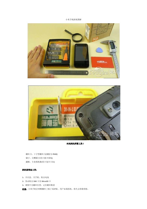
小米手机拆机图解本次拆机所需工具↓螺丝刀:十字型螺丝刀(规格为PH00)镊子:尖嘴镊子(用于拨开排线)撬棒:专业拆机棒(用于划开卡扣)拆机前准备工作:1:开后盖、关手机、取出电池2:务必取出SIM卡及MicroSD卡3:观察中壳螺丝位置,记住螺丝数量注意:小米手机在两颗螺丝上贴了易碎帖,用户如果拆机,将失去保修资格。
包装盒的秘密:似乎雷军对小米手机的工业设计非常有信心,到8月16日正式发布,我们都看到了这张“透视图”。
这张“透视图”标注了小米手机几个核心部分,其中最吸引人的当属高通MSM8260 1.5GHz处理器。
我们将以这张图为模板,亲自拆机去探寻小米的真实状况...小米手机背壳共有8颗螺丝,全部位于显眼处,由于螺丝均采用PH00小号十字螺丝,所以拧动的时候容易脱丝。
小编不建议用户自行拆机,不仅失去保修资格,而且螺丝也容易“毁容”。
拆解小米手机真是非常方便,只需要拧开8颗螺丝,就可以直接动用撬棒了,沿着中壳边缘轻轻划动,用力务必均匀适中。
比起此前打开Xperia Play及OPPO X903的背壳,小米手机简直容易太多了。
这样的设计也很显而易见,售后维修这个环节可以更加快速方便。
仅需“卸下螺丝”+“顶开卡扣”两个环节,我们就能拆开小米手机的背壳,一睹它的绿色PCB主板真容了。
初略看过去,小米手机的主板集成度非常高,零件紧凑且整齐的排列着,给人一种非常扎实的主观感受。
左边这个圆形部件疑是MIC话筒,右边那个方形部件确认是独立扬声器,这枚扬声器的音量非常巨大,某些标榜为“音乐手机”的手机也望其项背。
大家是否还记得,小米手机发布会上,雷军提炼出了小米手机的6大优势,其中1大优势就是信号好。
根据雷军的说法,小米手机采用了大面积隐藏式天线设计,背壳上部及下部均为天线贴片,这样不仅能够增强信号,据说将天线贴片分摊在机身多处还能降低辐射。
背壳上方天线贴片(摄像头上围一圈)背壳上方内侧,左右两侧金属触点是天线连接触点,左上角那个金属触点是3.5mm耳机插孔。
索尼XPERIA使用说明书

使用入门.........................................................................................8 组装....................................................................................................8 打开手机.............................................................................................9 屏幕锁................................................................................................9 安装向导.............................................................................................9 帐户和服务.......................................................................................10
电子邮件.......................................................................................38 使用电子邮件....................................................................................38 使用电子邮件帐户............................................................................40 Gmail™ 和其他 Google™ 服务 ........................................................40
索尼 Xperia Z3 Dual LCD 屏幕更换说明书

索尼 Xperia Z3 Dual LCD 屏幕更换索尼 Xperia Z3 Dual LCD 屏幕更换撰写者: Sophia介绍[video: https:///watch?v=hzuGqykkrY4]这个是支持博客博客,将会提供更多的细节信息。
工具:Heat Gun (1)Suction Handle (1)iFixit Opening Picks set of 6 (1) Spudger (1)iFixit Opening Tools (1) Phillips #00 Screwdriver (1)章节:Sony Xperia Z3 LCD Screen and Digitizer (1)Sony Xperia Z3 Display Adhesive Strips (1)步骤 1 — LCD屏幕使用热风枪来软化后壳周围的粘合剂。
使用吸盘来打开一个缺口,然后插入一个吉他拨片。
小心地使用吉他拨片来切割粘合剂。
如果您使用太大的力气可能会破坏玻璃。
步骤 2移走背壳,扫一眼手机内部。
断开电池连接插头。
将电池底部的胶带拨起。
使用胶带小心地将电池移走。
步骤 4这是索尼Xperia Z3 Dual 3100mAh的电池。
使用十字螺丝刀来卸下两颗螺丝。
释放三个连接到扬声器组件的连接头。
拆下振动器固定支架(某些设备上可能是可选的步骤)。
步骤 6移走扬声器组件外壳。
提示:在您向上拉的时候,将其朝向手机的中心。
撬起,移走扬声器组件。
在这里小心地松开麦克风。
小心地移走金属LCD 柔性电缆外壳。
从主要的柔性线缆上断开LCD 连接插头。
从下面的贴纸上小心地撬起LCD 连接插头。
步骤 8移走屏幕与打开后壳方法一致。
加热,打开个缺口,插入一个吉他拨片,滑动然后切割粘合剂。
从顶部开始。
提示:在这里的粘合剂粘得很牢固,您有可能需要在开始的时候插入一些锋利的工具。
要重新组装您的设备,请按照本指南的相反顺序进行操作。
自用vivo xplay拆解
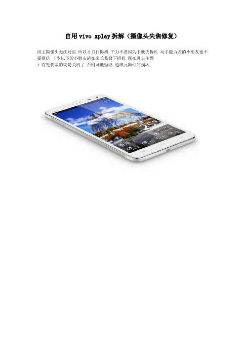
自用vivo xplay拆解(摄像头失焦修复)
因主摄像头无法对焦所以才自行拆机千万不要因为手贱去拆机动手能力差的小朋友也不要模仿十岁以下的小朋友请在家长监督下拆机现在进去主题
1.首先要做的就是关机了否则可能短路造成元器件的损坏
2.我所用的拆机工具就比较简陋了一把小刀一把十字小螺丝刀建议不要使用锋利的工具因为锋利的工具会造成塑料件变形金属件也极易划伤
3.用小刀将两头的塑料外壳撬开因此处无螺丝固定所以当卡口撬开后就可以直接取出了
4.用取卡针取出卡托和小卡
5.到了拆卸后盖的时候了很简单拆掉六颗固定螺丝然后将后盖向下滑动(有卡扣)就可以直接拆掉
6.现在就能看见3400毫安电池静静的躺在里面
7.拆卸元器件保护壳咯这里要提的就是因为保修标签贴在螺丝头上的所以在保修期内的童鞋要三思哦
8.元器件保护壳主要集成了两个扬声器(上下各一个)外放效果非常nice
7.所有的硬件基本就一目了然了现在拆掉电源线卡扣和主摄像头卡扣就可以拆掉主板值得一提的是xplay采用了一块5.7英寸1080p(1920*1280)ips全贴合显示屏显示效果极其细腻
9.后置摄像头为1300万堆栈式摄像头前置摄像头为500万其他的模块和芯片就不提了说说xplay的主打功能吧 hifi音效其内置有三颗hifi专业音质芯片(独立CS4398专业级音频解码器、CS8422 SRC信号转换芯片、OPA2604芯片的运放芯片)可以说是目前拥有最好音效的手机
10.现在说说针对手机摄像头无法对焦怎么处理吧手机的摄像头和单反的镜头一样都是可以手动调节焦距的(左右旋转)首先需要我们对手机进行开机然后打开相机然后就可以左右旋转手机摄像头的前端要注意的是调节的时候必须调节微距如果以长焦为标准调校的话微距会对不准还有就是保证不要刮花镜头也不要认镜头进去异物。
脑洞大开!带你探秘Xperia Z4-Z3内部架构

脑洞大开!带你探秘Xperia Z4/Z3内部架构
不少用户称赞索尼Xperia Z4/Z3 的Micro USB裸露且防水的设计,加之选择性上国行版索尼Xperia Z3拥有黑、白、琥珀色可选,国际版多增紫钻版以及水绿色选择,外观采用了与前代Z2类似的机身设计,Z3的边缘相比Z2不同的点是一体化设计的,中框直连接前后玻璃面板,同时索尼也在中框部分使用了铝镁合金材质更加纤薄,机身厚度从前代的8.2mm变为了7.35mm,受到消费者的热捧,为满足友的好奇心,编者特整理了Xperia
Z4/Z3 内部拆解过程,供读者品读。
加上高通810过热带来的负面影响,更是吸引不少玩家好奇该机内部结构,接下来就跟着拆解一起来看看这款索尼移动新旗舰外部设计“不变”的同时内部有何变化咯。
加热后背一周密封胶之后,用撬板去掉玻璃后壳。
诺基亚5000拆机图
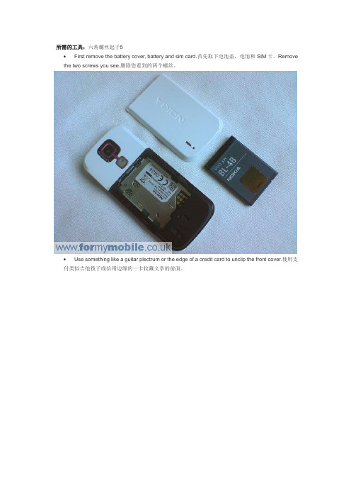
所需的工具:六角螺丝起子5∙First remove the battery cover, battery and sim card.首先取下电池盖,电池和SIM卡。
Remove the two screws you see.删除您看到的两个螺丝。
∙Use something like a guitar plectrum or the edge of a credit card to unclip the front cover.使用支付类似吉他拨子或信用边缘的一卡收藏文章的前面。
∙You should now have the cover and keypad removed, like below.你现在应该有盖和键盘删除,象下面这样。
Remove the four screws you can see.把四个螺丝可以看到。
∙Lift the main body of the phone away from the back cover.拿起手机的主体远离后盖。
Lift from right to left, like below.电梯由右至左,象下面这样。
Your phone you now look like below.您的手机你现在看起来象下面这样。
The LCD screen is attached to the circuit board by a ribbon.液晶屏幕是连接到电路板由一个剪彩。
This connects like a plug and socket. Simply lift the connector (circled) up, away from the phone to unplug it.这就像一个连接插头和插座。
只需解除连接器(圈)了,远离手机拔掉它。
∙Two metal clips on either side now hold the LCD frame to the circuit board.任何一方的两个金属夹上现在持有的LCD帧的电路板。
IPhone拆机详细步骤图解教程

IPhone4 拆机详细步骤图解教程要说在前面的是,拆机时要把螺丝按顺序放好,不然你会后悔的,推荐用双面胶贴在纸上,注明编号的顺序。
(郁闷的是home键的更换几乎要拆到最后一步)先拧开底部两个螺丝,注意梅花和十字的区别,需要先买专用拆机螺丝刀,内部螺丝全是十字的,一个螺丝刀通用哦。
拆下螺丝,背壳向上推,就能拿下来了看到电池,看来换电池还是很方便的嘛拧开电源固定螺丝拨开电源卡簧拉动旁边的塑料垫纸,电池下有双面胶,拉的时候小心,电池拿下注意卡簧下有一个垫片,别搞丢了取出SIM卡槽这个是扬声器话筒排线的压片,两个螺丝,注意大小撬开扬声器话筒排线的卡口小心拉起排线,下面有双面胶,别拉断了这是天线的接头,拔开,是扣上去的拧螺丝,注意螺丝大小取下主板上的压片,虽然有倒钩,但还是很好取的,没图上那么复杂撬开主摄像头的排线,摄像头直接拿下,更换摄像头到此为止看到白点了么?这是苹果的验水避孕试纸,遇水即红,整机中一共3个,图中2个,还有一个在耳机插孔里,这三个圆点一个变红,即不保修哦。
用针小心挑开试纸放好,露出下面螺丝,拆开主板上方有还有5个元件卡口,分别撬开,好像分别是触摸屏、液晶屏、前摄像头、耳机感光,还有各按键的排线,不管它,全部撬开撬开后是这个样子的,红圈的螺丝是最妖的一个,需要很薄的一子螺丝刀,别说我没提醒按这个方向提起主板,就能拿下主板了移开卡片,前摄像头就下来了,前摄头更换到此为止接下来是话筒扬声器天线模块,继续拆螺丝拿下来拿下来后是这个样子的,把天线剥下来,自此天线、扬声器话筒更换到此为止这个是震动马达,拆开螺丝直接拿下,自此震动马达更换结束接下来是电源、耳机模块的拆卸,按图片拆没有问题的,地道的白色换壳机是连这个模块也要换掉的哦电源键也可以更换静音音量键排线比较复杂点,但还不是很难,别弄丢了小部件哦如果只是单纯更换按键,还是比较简单的,看到木有?接下来是拆开机器底部数据DOCK模块,注意第一张照片要先拨起HOME键的排线卡口哦,地道的白色换壳机这个模块也要更换,和耳机模块一样,里面是白色的,但是因为拆开这两个模块比较麻烦增加风险,很多JS都不换的,所以大部分的白色换壳机都一目了然,屏幕白的,耳机孔和数据孔是黑色的,而原厂白机这两个模块露出的部分都是白色的。
荣耀play4Tpro更换喇叭教程

荣耀play4Tpro更换喇叭教程
01
首先使用螺丝刀把外壳的2只螺丝拆出,这是一体智能机,手机盖比较难拆的。
02
然后从拆螺丝的位置开始,用手指甲慢慢找到缝隙。
稍稍用力并移动一点。
03
接着把备好的塑料片插入指甲撑开的缝隙里。
这里使用的是医院拍片的那种塑料片,用剪刀剪成三角形的片。
04
使用指甲配合塑料片把手机两边都插入至少一张。
然后再慢慢把拆螺丝的这一端扳开一条小缝隙,这样就顺着缝隙就可以打卡手机后盖了。
05
接着把手机屏幕向下平放在台子上,找到手机喇叭位置,为了更准确的可以事先购买好该手机的喇叭配件,对照配件找位置比较容易。
06
使用小号螺丝刀小心的拆卸喇叭组件。
边拆边查看螺丝的数量。
07
在确认组件的安装螺丝数量被完全拆下后再取下喇叭组件。
严谨硬撬取件。
08
再次把原喇叭与配件喇叭组件进行对比。
并把原组件上的一些小配件,比如垫片,隔离垫,保护套等都取下,再安装在新组件上。
09
在安装组件之前,把原绝缘垫粘贴在耳塞孔周围,最后把组件放入手机安装位置。
10
最后把拆下的螺丝如数的安装好,并安装好各垫片。
确认安装无误后开机测试,声音正常。
就可以盖好后盖。
索爱音响盖拆卸方法
索爱音响盖拆卸方法引言索尼音响以其高品质音效和精致设计而闻名于世。
然而,有时候我们需要拆卸音响盖以进行维修或更换部件。
本文将为大家介绍索尼音响盖的拆卸方法,旨在帮助读者更好地操作索尼音响。
准备工具在拆卸索尼音响盖之前,我们需要准备以下工具:1. 螺丝刀组合套装:用于拆卸螺丝2. 塑料刮板:用于协助拆卸盖板时不会损坏表面3. 可能需要的其他工具:如扁头螺丝刀、剥线器等确保在操作过程中使用正确的工具,以免损坏音响盖。
拆卸过程根据音响型号的不同,拆卸方法可能会稍有差异。
下面是一个基本的拆卸步骤,供参考:第一步:关掉音响在拆卸音响盖之前,务必关掉音响并断开电源。
这是为了确保安全和避免任何电容器可能存在的电击风险。
第二步:查找和拆卸螺丝仔细检查音响盖的周围,找到固定音响盖的螺丝。
这些螺丝通常位于音响盖的底部或侧面,具体位置根据型号会有所不同。
使用螺丝刀组合套装中的正确螺丝刀,轻轻转动螺丝,将其拧松并取出。
注意要收集好拆卸的螺丝,以免遗失。
第三步:使用塑料刮板拆卸音响盖当所有螺丝都被取出后,可以使用塑料刮板或者类似的平滑工具插入音响盖和音响主体之间。
然后,轻轻移动刮板以解除音响盖与主体之间的卡扣。
用手轻轻提起音响盖,确保没有任何剩余的固定物。
如果遇到抵抗,请检查是否有任何遗漏的螺丝未取出。
第四步:注意内部电线和连接器在完全拆卸音响盖之前,必须注意内部电线和连接器的位置。
不要强行拆卸,以免损坏电线或连接器。
检查内部连接器是否固定并牢靠。
如果需要拆卸连接器,则小心地解除连接器插头。
请记住连接器的位置和插头的方向,以便在重新组装时正确连接它们。
第五步:完成拆卸在确认所有连接器已解除并将其位置妥善记录后,音响盖就可以完全拆卸了。
将音响盖放在安全的位置上,以免损坏。
结束语通过正确拆卸索尼音响盖,我们可以进行维修、更换部件或者进行其他操作。
但是需要记住,在拆卸前确保电源被切断,并且在操作过程中要小心处理内部电线和连接器。
主打时尚而并非配置,酷派ivvi K1拆解
主打时尚而并非配置,酷派ivvi K1拆解
酷派在2014年底推出了继大神之外的又一全新品牌ivvi,并且推出了一款K1手机。
据悉,这个品牌主打时尚而并非配置。
采用双镜面的设计,厚5.9mm,重约110g,机身纤薄。
先分别取下卡槽,K1的三个卡槽上都有标记,卡槽的正反以及功能。
取后盖是一个艰难的活,因为后盖采用的是蓝色镜面玻璃,酷派方面宣称这是“流光宝石镜面玻璃”。
拆下后盖的时候非常小心,以防弄碎玻璃。
然而拆下后才发现,其实后盖并非直接与主机身直接相粘的,而是中间还有一层塑料纸,玻璃被盖和主机身主要通过中间的这层玻璃纸实现贴合。
拆下塑料纸后我们拿着后盖观赏了下,由于后盖采用的是镜面玻璃,所以它在一些情况下,可以直接当做镜子来“使用”。
但是镜面的后盖,诚然是比较美观而且具有视觉冲力,但是随之而来的问题是特别容易沾染指纹和油污,特别对于那些强迫症患者而言,几乎随时随地都要擦拭,没法好好使用。
如图所示,仅仅轻轻接触,后盖左边就留下了一个痕迹。
电池的设计,如同iPhone的电池一样,采用了那种可以撕扯掉的胶带。
P800拆机全教程

P800拆机全教程(拆机风险极大,仅供参考)
【郑重声明】:拆机风险极大,请动手之前三思,本帖仅供大家赏
玩!!!
【准备工作】:三个工具就够了,一把T5内六角的螺丝刀,一把开壳螺丝刀(也可以用弯嘴镊子),一把小十字螺丝刀。
【拆机步骤】:
第一步:用开壳螺丝刀挑松天线盖,左右都要挑松
第二步:用手向头部用力推,并拉出天线盖
第三步:拧开四颗T5螺丝
第四步:用指甲挤开中壳(如果你的指甲够硬够好的话)也可以用SIM 卡或是其他硬点的塑料卡片之类挤开
第五步:拧开主板上的两颗小梅花螺丝
第六步:推开屏幕排线压片,拨开屏幕排线
第七步:推开按键排线压片,拨开按键排线
第八步:拆屏幕,用开壳螺丝刀从卡口处挑开卡口,左右共两个
第九步:挑开卡口时,并用指甲挤开侧条,左右两边都挤开
现在,屏幕部分就拆开了
拆掉屏幕,这是前壳按键部分
这是面壳
P800的液晶
传说中的鼠标
【全家福】
[本帖最后由muamufff 于2008-9-22 13:44 编辑]。
sony S系列拆机方法

sony S系列拆机方法04月 30th, 2005 by 记得认识棉花是因为当时棉花在经纬论坛贴了一些717拍的照片,那张微距五角给我得我印象很深。
他还发过一篇他朋友的VAIO的台机照片。
当时就被sony的设计所吸引了。
谢谢爸爸妈妈给我的礼物,我选择了Sony S的本本,这是最后几次花家人的钱了^_^。
S系列都是13寸宽屏。
配置是dothan的cpu,512ddr,ATI9700的显卡,但是硬盘只有4200转,这点让我不可忍受,硬盘的瓶颈太大了,以致比以前的p3机器还要慢。
所以拿着它去武汉sony客服想换个硬盘,结果不给换。
那只有自己动手了哦。
注意一点就是,如果在保期内,出了问题,sony要是知道你换了硬盘,那就不好办了,但是出了问题,可以再把sony原配的硬盘换过来嘛。
因为机型比较薄的缘故sony S系列的硬盘不像一般BB那样好拆。
S的硬盘再右边托手板下方,如果换成5400转的,发热量要大些。
所以大家动手之前要考虑清楚哦,一个是保修问题,一个就是噪音和发热量。
准备工具就是螺丝刀、镊子、还有就是BB。
1,先把背面的螺丝全部取下,如图,两个内存盖螺丝,10个机身螺丝。
2,机身底部的螺丝全取下之后,键盘就可以取下来了,图中就是卡住键盘的东西,用软性东西,比如身份证之类的撬开。
3,键盘下方有个数据线连接口,按照箭头方向往上拨开,数据线就出来了,我还用了镊子,因为开始不知道是怎么取下。
用手指往上拨,很轻松的。
4,拆完键盘,就可以看到底座了,左边有两个电源线,是给喇叭供电的,中间上面是上面一排按钮的数据线,中间靠下是触摸板数据线。
取下5个螺丝,触摸板所在的整个面板就可以取下了,我是用身份证刮开的,四周都有塑料卡槽。
5,给喇叭供电的电源线用镊子夹住往上拉就可以取下来。
6,还有刚提到的两根数据线,这个数据线只要用手指捏住往上取就可以了。
7,取下面板就可以看到硬盘了。
有网友反映这里取不下来,其实两旁是有塑料卡子卡住的,稍微用点力就可以取下来的。
索尼Xperia Z3 Compact LCD屏幕更换说明书

索尼Xperia Z3 Compact LCD屏幕更换更换索尼Xperia Z3 Compact上的显示屏。
撰写者: Sophia
介绍
解决索尼Xperia Z3 Compact上显示屏破碎问题。
在这个视频之后,您可以自己修复破碎的Xperia Z3 Compact的屏幕。
[视频链接|https:///watch?v=ibb22uof...]
请注意,本指南介绍如何更换LCD +触摸屏组件。
替代维修是取代LCD +触摸屏+中框,可以作为预装组合购买。
章节:
Original LCD Screen for Sony Xperia Z3 Compact (1)
步骤 1 — LCD屏幕
取下背壳。
步骤 2
取下后架。
重新安装:银色螺丝(2)位于框架的侧面。
顶部和底部的金色螺丝(3)。
拉出LCD 屏幕连接器。
步骤 4
步骤与取下后盖相同但更困难。
加热3分钟,用更多的精力翘起贴纸,仔细拿着屏幕与筒。
但是为什么索尼Xperia Z3 Compact 拆解屏幕会带有耳机? 答案是听筒直接粘在触摸屏上,没有任
何支架。
所以为了避免损坏听筒,我们需要非常小心,沿着顶面切割贴纸。
注意方向,卸下听筒。
要重新组装您的设备,请按照该指南并按照相反的顺序重新组装。
从屏幕上取下听筒。
当您装上新屏幕时,您需要将其放回原位。
华为荣耀8拆机视频教程

华为荣耀8拆机视频教程华为荣耀8是一款备受瞩目的手机,有很多人对它的内部结构和拆机方式非常感兴趣。
本文将为大家提供一篇详细的华为荣耀8拆机视频教程,希望能够为大家解答疑惑。
首先,我们需要准备一些必要的工具。
拆机工具包括螺丝刀、开胶器、吸盘、塑料片等。
在开始拆机之前,请确保手机已经关机并断开与电源的连接。
第一步,使用吸盘轻轻吸取手机背面的玻璃壳。
然后,用塑料片插入背壳与机身之间的缝隙,小心地撬开背壳。
请注意,不要用力过猛,以免损坏手机。
第二步,打开背壳后,我们可以看到手机的内部结构。
首先,需要拆下电池。
华为荣耀8的电池是可拆卸式的,所以我们只需要用力将电池从机身上取下即可。
第三步,接下来,我们要拆下手机的背后保护板。
使用螺丝刀拆下保护板上的螺丝,并小心地取下保护板。
在拆下保护板之前,还需要拆下摄像头连接线,这样才能完全打开保护板。
第四步,拆下保护板后,我们可以看到手机主板。
主板上有许多重要的零部件,如处理器、存储芯片等。
在拆卸主板之前,我们需要卸下主板上的各种连接线,如显示屏连接线、摄像头连接线、音频连接线等。
第五步,将主板上的各种连接线都插下后,小心地取下主板。
在取下主板之后,我们可以看到一些其他的零部件,如扬声器、震动马达等。
如果需要继续拆下这些零部件,可以按照相同的步骤进行操作。
通过以上步骤,我们可以完成华为荣耀8的拆机过程。
拆机过程中需要注意细节,尽量避免过度用力,以免损坏手机。
总结起来,华为荣耀8的拆机过程并不是非常复杂,只要有一定的耐心和细心,就可以完成。
通过拆机过程,我们可以更加深入地了解手机的内部结构,并对手机的组装和维修有更深入的了解。
当然,在拆机过程中需要格外小心,避免对手机造成损坏。
希望以上的华为荣耀8拆机视频教程能够对大家有所帮助,如果有任何疑问或意见,欢迎留言讨论。
- 1、下载文档前请自行甄别文档内容的完整性,平台不提供额外的编辑、内容补充、找答案等附加服务。
- 2、"仅部分预览"的文档,不可在线预览部分如存在完整性等问题,可反馈申请退款(可完整预览的文档不适用该条件!)。
- 3、如文档侵犯您的权益,请联系客服反馈,我们会尽快为您处理(人工客服工作时间:9:00-18:30)。
本帖最后由 SAILOR-HB 于 2011-12-11 01:45 编辑
同志们,你们的XPERIA PLAY开始花屏了吗?可能你会说没有,不过,做好心理准备吧,早晚会面对这一事件的。
本人的XPLAY玩机频率较高,加上有一次开着滑盖一P股坐上去了(幸好屏幕没碎),当时没什么,后来逐渐出现花屏的现象,怀疑排线故障了。
后来越来越频繁,渐渐影响使用了,无奈购买了2条排线(一条备用),每条40元(说实话真不贵,去年X1排线卖到150,当然X1的比这个稍微复杂那么点儿),今天收到货了,虽然出差在外,幸好带上了点工具。
拆,换!由于工具不全,过程遇到了好多难拆的地方,后来也逐一解决,过程拍了些照片,在此贴出,供大家参考。
必备工具:T4六角螺丝刀,PH00小十字螺丝刀,镊子。
选配工具:撬片(有这个会轻松很多)。
开拆!
网上搜索“Xperia Play 拆机”,可以找到那个全球首发的文章,这篇文章对于拆后盖拍的很详细,这里我引用他几张图片。
第一部分,拆后壳
第1步,卸掉后壳的13颗螺丝:
拆掉了:
第2步,揭开这2处胶贴,并撬开后壳:
撬开之后的样子:
第3步,拔掉耳机插口的连接线,并拆掉耳机插口
第4步,卸掉主板上2颗小十字螺丝,然后掀开一点主板,把排线扣掉,然后继续掀,把触摸摇杆的连接
线也拆掉:
拆完之后:
第二部分,拆前壳:
第5步,揭开屏幕部分的2个螺丝胶贴,并卸下4颗
小十字螺丝:
第6步,把触摸屏的连接线拆掉,并撬开前壳(这里很难撬开,要小心点!)
第7步,把液晶屏拆掉,露出排线和几处连接线:
看看我们的屏幕:
第8步,揭开这层半透明的胶布
看看原来屏幕的那一面
第9步,揭开这层金属胶布
第10步,揭开这层挡板
第11步,把排线从铁皮上揭下来(用镊子撬开)
第12步,把排线折一下,然后从孔里抽出来(注意
技巧)
看看我们的排线
第三部分,安装:
看看新买来的排线
第13步,重点!!注意!!最好先拿旧排线练习几次再装!!小心地把新排线稍微弯折一下(不然塞不
进),慢慢地塞进限位孔。
注意别装反了。
第14步,整理好、粘好新排线后,依次插上各个连
接线,盖好金属挡板,贴上原来的金属胶布
第15步,反过来,贴好那层半透明胶
第16步,安装屏幕(装完擦干净指纹)、前壳,插好触摸屏的排线,这条线非常难插,一定要注意!触
摸屏卖150大洋,可要小心啊!
第17步,装好主板、耳机插口、后壳,大功告成!
不花屏真舒坦啊!!
看看我们换下来的旧排线,它就是花屏的罪魁祸首!
2011-12-11 01:07 上传
下载附件(466.78 KB)。
