Resolution MEPC.157-55
中文IMO resolution (2010-1-1 to 2010-7-1) list

MSC.270(85)
MSC.201(81)
1974 SOLAS公约修正 案 ADOPTION OF AMENDMENTS TO THE INTERNATIONAL CONVENTION FOR THE SAFETY OF LIFE AT SEA, 1974, AS AMENDED MEPC.184(59) 经修订的废气清洁系统 导则 2009 GUIDELINES FOR EXHAUST GAS CLEANING SYSTEMS MSC.207(81) LAS规则 ADOPTION OF AMENDMENTS TO THE INTERNATIONAL LIFE-SAVING APPLIANCE (LSA) CODE MEPC.181(59) 经修订MARPOL附则VI 的2009年港口国检查导 则 2009 GUIDELINES FOR PORT STATE CONTROL UNDER THE REVISED MARPOL ANNEX VI MSC.201(81) 1974 SOLAS公约修正 案 ADOPTION OF AMENDMENTS TO THE INTERNATIONAL CONVENTION FOR THE SAFETY OF LIFE AT SEA, 1974, AS AMENDED MSC.269(85) 1974SOLAS公约修正 案 ADOPTION OF AMENDMENTS TO THE INTERNATIONAL CONVENTION FOR THE SAFETY OF LIFE AT SEA, 1974, AS AMENDED MEPC.185(59) VOC管理计划制定导则 GUIDELINES FOR THE DEVELOPMENT OF A VOC MANAGEMENT PLAN
压载水管理计划 BWMP (MEPC 127 (53))

压载水管理计划BWMP (MEPC 127 (53))BALLAST WATERMANAGEMENTPLAN (MANUAL)To meet the requirements of Regulation B-1 ofINTERNATIONAL CONVENTION FOR THE CONTROL AND MANAGEMENTOF SHIP’S BALLAST WATER AND SEDIMENTS, 2004AND THE IMO RESOLUTION MEPC. 127(53)GUIDELINES FOR BALLAST WATER MANAGEMENT AND DEVELOPMENTOF BALLAST WATER MANAGEMENT PLANS (G4)This plan should be kept available for inspection on request by a port state control officer or by a port state quarantine officer.1. This Manual is written in accordance with the requirement of Regulation B-1of the International Convention for the Control and Management of Ship’s Ballast Waterand Sediments, 2004( the convention) and the associated Guidelines.2. The purpose of the Manual is to meet the requirements forthe control and management of ship's ballast water and sediment in accordance with the guidelines for the ballast water Management and the Development of Ballast Water Management Plans resolution MEPC 127(53)(The Guidelines).It provides standard operational guidance for the planning and management of ship’s ballast water and sediments and describes safe procedures to be followed.3. This plan may be inspected on request by an authorized authority.4. It is the owners/operators or master’s responsibility to regularly review the plan and ensure that the informationcontained therein is accurate and updated.Note: The Plan is to be written in the working language of the crew, if the text is not in English, French, or Spanish, theplan is to include a translation into one of these languages.- 1 -Ship’s Name Ship type Owner Manager FlagPort of Registry International Call Sign Classification Society Gross Tonnage IMO Number Length (OA) Length (BP) Beam Depth Summer Load DraftDeepest Ballast Drafts( Normal Ballast and Heavy weather Ballast ) Total Ballast CapacityBallast Water Management Methods UsedIdentification(Rank) of Ballast WaterManagement Officer- 2 -This document to be circulated to ships stuff that will be responsible for Ballast Water Management, by the holder of the copy.After reading, the Ballast Water Management Plan it is to be signed and Returned to the Ballast Water Management OfficerNameRankDate JoinedSignature and date- 3 -When any change/amendment is made to chapter, a new ‘Table of Contents’ page shall also be sent together with the relevant amended chapter.The holder of the controlled copy shall enter all amendments made to this document and register such changes in those pagesRevised Revisiondetail / descriptionSignatureMaster of SignatureCONTENTSParticulars of Circulation of Amendments Section 1 Section 2 Section 3 Section 4 Section 5 Section 6 Section 7 Section 8 Section 9 Section 10 Section 11 Section 12 Section 13 Section 14 PurposePlan / Drawing of Ballast System Description of the Ballast System Ballast Water Sampling PointsOperation of the Ballast Management System Safety Procedures for the Ship and CrewOperational or Safety RestrictionsDescription of the Method(s) used on board for Ballast Water Management and Sediment Control Procedures for the Disposal of Sediment Methods of CommunicationDuties of the Ballast Water Management Officer Recording RequirementCrew Training and Familiarization ExemptionsAPPENDICESAppendix 1:PlansAppendix 2:Summary forms of Ballast water exchange sequences and Print out for each step calculation results Appendix 3:Assessment Criteria for Sequentialand Definition of Sea State according to WMOAppendix 4:Blank FormsAppendix 5:List of Reference DocumentsAppendix 6:National or Local Quarantine Requirements for the Control And Management of Ship’s Ballast water and Sediments- 5 -Ballast water is essential to control trim, list, draft, stability, or stresses of the ship.However, Ballast water may contain aquatic organisms or pathogens, which, if introduced into the sea including estuaries, or into fresh water courses, may create hazards to the environment, human health, property or resources, impair biological diversity or interfere with other Legitimate uses of such area.The selected methods of ballast water management take into account the need ensure that Ballast Water Management practices used to comply with this Convention do not cause greater harm than they prevent to the environment, human health, property or resources of any State and the Safety of the ship.It is estimated that at least 7,000 different species are being carried in ship’s ballast tanks arou nd the world.Studies carried out in several counties indicated that many species of bacteria, plants, and animal can survive in a viable form in the ballast and Sediment carried in ships, even after journeys of several months’ duration.Subsequent discharge of ballast water or sediment into the waters of Port States may Result in the establishment of harmful aquatic organisms and pathogens which may pose threats to indigenous human, animal and Plant life, and the marine environment.When all factors are favorable, an introduced species by survive to establish a reproductive population in the host environment, it may even become invasive, out-competing native species and multiplying into pest proportions.Although other media have been identified as being responsible for transferring organisms between geographically separated water bodies, ballast water discharge from ship appears to Have been among the most prominent..As a result IMO has developed guidelines for the development and implementation of a Ballast Water Management on board ship aiming to assist Governments, appropriate authorities, ships masters, operators, owners and port authorities, as well as other interested parties, in the preventing, minimizingand ultimately eliminating the risk of introducing harmful aquatic organisms and pathogens from ship’s ballast water and Associated sediment while protecting ship’s safety.Good record keeping is critical to the success of a sound ballast water management program.The appointed ballast water management officer is responsible for ensuring the maintenance ofappropriate records and that ballast water management and / or treatment procedures are followed and recorded.The function of the Ballast Water Management Plan is to assist in complying with IMO Guidelines and quarantine measures intend to minimize the risk of transplanting Harmful aquatic organisms and pathogens from ships’ ballast water and associated sediments, while maintaining ship safety.As part of this function the plan provides information to port state control and other authorized officers about a ship’s ballast handling system, sampling points and ballast water management system.The plan should not be used or regarded as a guide to ballasting.- 6 -The following plans, which are located in Appendix 1, illustrate the ballast water system arrangements and ship’s capabilities and are to be used to assist the crew in understanding and following the Ballast WaterManagement Plan:1. General Arrangement.2. Capacity plan with Deadweight Scale3. Piping Diagram of Ballast System4. Pumping Diagram of Ballast System in Engine room5. Schematic Diagram of Sounding pipe and Air Escape Pipe6. Manhole Arrangement for Ballast Tanks- 7 -The following is a description of the ballast system used onboard. Reference Plan can be found in Appendix 1.Ballast Tank DataTankLocation( Frame Nos. )Capacity( ? )Pumps availablePump Data- 8 -Overflow and Filling Line Data ( for flow through method )TANKNo. ofOverflow Lines per tank (Air vents or overflow lines per tank)Overflow line nominal diameter (mm)Overflow lines total cross section area (mm2)Filling line Nominal diameter (mm)Filling line Total cross sectional area (mm2)RATIO of Overflow / Filling line total cross sectional areaAll Water Ballast Tanks satisfy the minimum requirements for Vent, Sounding, and Overflow Pipes, as stated below:Where tanks are filled by pump pressure, the aggregate area of the vents for tank is to be at least 125% of the effective area of the filling line, except that when overflows are fitted, the area of the overflow is to beat least 200% of the effective area of the fill line and the vents need not exceed the above minimum sizes.In addition, the pump capacity and pressure head are to be considered in the sizing of the vent and overflows ; where high capacity or high head pumps are used, calculations demonstrating the adequacy of the vent and overflow are to be submitted.- 9 -Sediment Control and Removal MethodsTankBottom FlushWater jetDe-mucking*Note:Mark [X] to be filled in to applicable method for each ballast tank.- 10 -Time Required For The Flow-through MethodBallast TankCapacity ( ? )Pumps Serving Specific TankTime for 3 Exchange*WARNING:(1) In case that Flow-through Method is being used, it is necessary prior to this operation to open the water tight manhole(s) of the corresponding tank.(2)It is recommended that only one pump should be used for ballasting and de-ballasting a single ballast tank.- 11 -Information regarding the location of the ballast water sampling points and sediment sampling points is contained in Appendix 1.Compliance monitoring may be undertaken by authorized officers ( e.g. Port State Control), by taking and analyzing ballast water and sediment samples from ship.There is unlikely to be any need for crew members to take sampleexcept at the express request, and under the supervision, of an authorized officer.Authorized officers must be advised of all safety procedure to be observed when entering enclosed spaces.Where ballast water or Sediment sampling for compliance or effectiveness monitoring is being undertaken, the time required to analyze the samples shall not be used as a basis for unduly delaying the operation movement or departure of the ship.When sampling for research or compliance monitoring, authorized officer (e.g. Port State Control ) should give as much notice to the master as possible that sampling will occur, to assist the Master in planning staffing and operation resource to assist.The Master has a general obligation to provide reasonable assistance for the above monitoring and information pertaining to ballast arrangements and sampling points.Port State Authorities should indicate to the master or responsible officer the purpose for which the sample is taken(i.e. monitoring, research or enforcement).Port State Authorities may sample or require sample to analyze ballast water and sediment, before permitting a ship to discharge its ballast water.- 12 -The necessity of pr-planning is to ensure that all safety consideration as addressed in Section 6 and 7 are in compliance with ballast exchange, ballast water treatment or other control options.1. Ballast Water ExchangeBallast water exchange in open water and the need to for exchange should be carefully examined and prepared in advanced, in a similar manner to the preparation of a cargo plan for a loaded voyage, and with the same degree of thoroughness.The Convention require that vessel should conduct ballast water exchange:At least 200 nm from the nearest land and in water at least 200 m in depth; if this is not possibleAs far from the nearest land as possible, and in all cases at least 50 nm from the nearest landand in water at least 200m in depth.In sea areas designated by the Port State.All local and / or national regulation should be taken into consideration as may specify other depths and distance from land.A ship will not be required to deviate from its intended voyage or delay the voyage in order to comply with any particular requirement as stated above.In addition if the master decides reasonably that an exchange wouldthreaten the safety or stability of the ship, its crew or its passenger because of adverse weather, ship design or stress, equipment failure, or any other extra。
MEPC157_55_文本_中英文对照版

环保会第MEPC.157(55)号决议2006年10月13日通过关于船舶未经处理生活污水排放速率标准的建议海上环境保护委员会,忆及《国际海事组织公约》关于由防止和控制海洋污染的国际公约赋予海上环境保护委员会(本委员会)职责的第38(a)条,注意到第MEPC.115(51)号决议,本委员会以该决议通过了经修订的《防污公约》附则IV,已于2005年8月1日生效,还注意到《防污公约》附则IV第11.1.1条的规定,认识到储存在污水舱的未经处理的生活污水不得随即排放,而应该以主管机关根据本组织制订的标准而批准的适当速率排放,审议了散装液体和气体分委会第10次会议提出的建议,1. 通过了关于船舶未经处理生活污水排放速率标准的建议,其正文列于本决议的附件;2. 建议会员国接受基于所附标准的排放速率,3. 鼓励排放要求高的船舶经营人保持其实际排放计算,以便向主管机关和港口或沿岸国当局表明其符合要求。
附件关于船舶未经处理生活污水排放速率标准的建议1 引言1.1 经修订的《73/78防污公约》附则IV第11.1.1条要求,可以在距最近陆地12海里以外排放的未经处理的生活污水不得随即排放,而应该以主管机关根据本组织制订的标准而批准的适当速率,在船舶以不小于4节的速度航行时排放。
本建议提供了批准和计算适当排放速率的标准和指导。
1.2 适当排放速率适用于船上污水舱储存的未经处理生活污水的排放。
1.3 本标准并不包括用水或中水稀释后的生活污水的排放速录计算。
因此,该速率是个保守的估计,可以认为根据本标准进行生活污水排放将对海洋环境提供更高水平的保护,因为除船舶航行过程排放产生的混合之外还有事前的混合。
2 定义2.1 “扫水量”系指船宽×吃水×航行距离。
2.2 “未经处理的生活污水”系指为没有经认可形式的生活污水处理厂处理过,或未经粉碎或消毒的生活污水。
3 排放速率3.1 最大允许排放速率为扫水量的1/200,000(或200,000分之一),计算如下:= 0.00926 V D BDRmax其中:为最大允许排放速率(m3/h)DRmaxV 为船舶在该段时间的平均速度(节)D 为吃水(m)B 为船宽(m)3.2 第3.1段中所列的最大允许排放速率指的是在任何24小时的时间段计算出的平均速率,或如果排放时间段小于24小时,在时间段内的平均速率,在每小时的基础上测量时可以超过,但不高于20%。
新的污水处理器SWCM系列英文说明书-150人
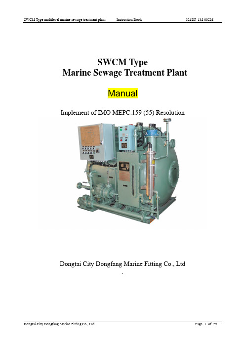
SWCM TypeMarine Sewage Treatment PlantManualImplement of IMO MEPC.159 (55) ResolutionDongtai City Dongfang Marine Fitting Co., Ltd.Marks:1 The sewage treatment plant as a TypeⅡmarine sanitation device, MSD can be used on un-inspected vessels.2 The device is designed to operate in salt or fresh water.3 The test pressure of the tank is 0.021MPa.4 The effluent quality of the device is in compliance with the standards ofIMO MEPC159(55, and 33CFR159 for type II device.WARNING:1 The plant cannot be installed in explosive atmosphere.2 Paint tar epoxy as that coat on inside surface of the tank, welding should not be worked on the surface of the tank.3 It needs clear space at front of device 600 mm and right side of device 300 mm to allow for operation and maintenance of the device.4 Any anti-virus agent can’t be used in the progress of device using.Type descriptionSWC M --- xxRated number of persons allowedMembrane Biological Reactor (MBR)SWCM seriesContents1 Preface2 Main technical performance3 System principles4 System description5 Electric control principle6 Operation7 Installation8 Troubleshooting9 Maintenance10 Scope of supply11 Contact usAttachment: System diagramNoteThe EPA standards state that in freshwater lakes, freshwater reservoirs or other freshwater impoundments whose inlets or outlets are such as to prevent the ingress or egress by vessel traffic subject to this regulation or in rivers not capable of navigation by interstate vessel traffic subject to this regulation. Marine sanitation devices certified by the U.S. Coast Guard installed on all vessels shall be designed and operated to prevent the overboard discharge of sewage, treated or untreated, or of any waste derived from sewage.The EPA standards further state that this shall not be construed to prohibit the carriage of Coast Guard-certified flow-through treatment devices which have been secured so as to prevent such discharges.They also state that waters where a Coast Guard-certified marine sanitation device permitting discharge is allowed include coastal waters and estuaries, the Great Lakes and impoundments accessible through locks, and other flowing waters that are navigable interstate by vessels subject to this regulation.(33CFR159)1 PrefaceThis plant is applicable to treat the sewage, which means human body wastes and the wastes from the toilets on vessels and which is also called “black water”, to meet the effluent standards of IMO MEPC.159(55), and discharge the effluent to overboard. It is also applicable to treat galley & shower drainage which is called “grey water” on condition that the “grey water” should be pretreated or should select a bigger capacity model to match with.Marine Sewage Treatment Plant belongs to the key devices for prevention of pollution form ships in seas and oceans according to the revised Annex IV of the International Convention of the Prevention of Pollution (MARPOL 73/78). The MEPC.2 (VI) resolution adopted on 3 December 1976 is the present guidelines on implementation of effluent standards and performance tests for STP, which is called “old standards”. This device is according to the MEPC.159(55) resolution enacted on 13 October 2006, which is called “new standards”. The c onvention (MARPOL 73/78) provides that all STPs installed on board on or after 1 January 2010 should meet the MEPC.159(55) resolution.Summary all the rules and effluent standards as followings:principle of biologic membrane to digest the organic pollutant, which can treat sewage effectively and reach at the IMO new effluent standard or other stricter requirements.The device is patent product, provided with independent innovation intellectual property. WarningMechanical HazardsBefore maintenance is performed on motor driven equipment, the main circuit switch should be off and labeled “OUT OF SERVICE”. Only authorized maintenance personnel can make repairs to equipment.Electrical HazardsThe equipment is supplied with high voltage that is dangerous and could prove fatal if contacted by personnel. Under no circumstances should any door or cover be removed or tapered in any way. To avoid electrical shock, remove the electrical power by placing the main circuit switch on “off” position, do this before performing any maintenance on electrical equipment or motors. Personnel should exercise extreme caution when opening the door of the electric control cabinet.Disease HazardsSewage is a common mode of transmission for parasite organisms such as bacteria, fungi, protozoa, viruses and worms; some of these may be pathogenic, meaning they have the capacity of causing serious communicable diseases. Most diseases associated with sewage result from hand to mouth transfer of the pathogenic organisms. Good personnel habits by those servicing or in any way coming in contact with the equipment are imperative.After coming in contact with sewage on any contaminated equipment items, personnel should thoroughly clean themselves with a disinfectant soap solution. This precaution is an absolute requirement before eating, drinking, smoking or performing any hand to mouth functions. Skin abrasions, punctures, or any other wounds require immediate and proper medical attention.2 Main technical performance2.1 Table of main technical performanceDongtai City Dongfang Marine Fitting Co., Ltd. Page 7 of 293 System principle3.1 Process principle; please refer to 321DF-1M-00XTThe device adopts activated sludge, contact oxidizing and principle of biologic membrane to digest the organic pollutant, which can treat sewage effectively and meet the IMO new effluent standard or other stricter requirements.The treatment procedures of the plants are shown as following:Sewage inlet aeration contact oxidation setting membrane sterilize dischargeIn the 1st stage aeration tank, the activated sludge mainly consisting of aerobic bacteria form sticky flock is used to absorb and digest the organic substance to carbon dioxide and water under the condition of aeration, and produce new activated sludge in the meantime. The bacteria will die owing to the decreasing of organic pollution substance. The death bacteria are digested by the protozoa and the metazoan, which attached in the active sludge. The 95% of the sewage is easy-digested organic substance, they are oxidized entirely.The s oft bio-film stuffing is hung in the 2nd stage contact oxidizing compartment. The bio-film, which can digest organic substance, is floated in water. Most of the protozoa and the metazoan live in the fiber film. The organic substance is further digested by the protozoa on film. If restarting plant after stopped for some while, the restarting time is much quicker than that of conventional aeration starting time, because of the bacteria existing in the spore on the membrane. Meanwhile, the soft stuffing, similar as “cotton boll”, is able to expand as over nutrition and absorb superfluous activated sludge, or digest themselves as lack of nutrition, which is also c alled “endogenous respiration”. The “cotton boll” will be shrunk and wait for the future nutrition.Then the sewage enters into setting tank and the sludge will settle as no aeration and with help of solid filter material. The activated sludge sediment accumulated in the setting tank is to be returned to the 1st stage aeration tank by the method of air lifting for reproducing of aerobe medium. The SV3 is opened each 30min and duration for 5min to return the sludge to 1st stage aeration tank. Please refer to the procedures in Figure 3The clear supernatant liquid then flows into membrane tank, and creates good operational conditions for membrane module. The membrane module placed in membrane tank is animmerged type and can create biochemical reaction, which is also called membrane bio-reactor (MBR). The membrane is made of hollow fiber ultra filtration material, through which the permeated clean water is sucked by vacuum pump, then disinfected by ultraviolet ray (or ozone), it can meet effluent standard, and discharge overboard or to clean holding tank on ships.It is designed automatic aeration procedure for the sludge sediment in membrane tank, the activated sludge in sediment tank also can be transferred to aeration tank automatically by “air lif ting” in regular. During this period, the activated sludge is in “hypoxia” status and achieves "simultaneous nitrification and deni trification,” which is useful to the "nitrogen and phosphorus removal" to reduce the ammonia content in effluent. It can solv e the problem of “bubble” caused by traditional continue aeration for active sludge.The vacuum pump is operated as per the Figure 1 procedure, i.e. running for 9min and stop for 1min automatically in regular, during the time of stopping, the scale on the membrane threads drops by no suction force, and aeration at same time, it is good for scrubbing the membrane threads to prolong the cleaning period. T he membrane can be cleaned “on-line” due the membrane tank is single closed structure, easily without taking out. The scale on the membrane threads can be cleaned quickly by feeding chemical into membrane tank, and aeration at same time, working as washing machine. Then the membrane flow flux can be recovered to original status. If only soaking but no aeration, the effect may be poor.The sludge discharge cycle depends on the sewage quality and load, It is appropriate to discharge the residual sludge once 6 to 9 months.3.2 Air pumpAir pump is used for transporting air to the plant. The air pump consists of main engine, air bag, base, lubrication, cooling parts etc. Main engine consists of pump body, rotor and sliding-vane etc. The rotation axis of the rotor is eccentric allocated to the cylinder. Self-lubricating sliding-vanes are fixed on the seven wedges of the rotor. The sliding vane owing to centrifugal force contacts the cylinder to form seven air chambers. When the motor drives the rotor through the clutch. The volume of each air chamber changes with the rotation of the rotor to form the vacuum. Compensate air halfway, then compress it to the rated pressure and discharge the compressed air without the oil.The air pump is classified into main air pump and lifting air pump, the both structures are same, but the functions are different.3.3 Cutting and discharge pumpCutting and discharge pump is the open impeller centrifugal pump, the sewage is cut and macerated by cutting pump to recycle or discharge it to overboard at the emergency time. The sewage in all tanks can be discharged empty, so long as open the corresponding bottom valves.3.4 Vacuum pumpVacuum pump is a centrifugal pump with stronger ability of self-suction, but it is better to keepsome water in the pipes to avoid the problem for restarting. It can create a certain difference pressure and make the water permeate the membrane. If the membrane is blocked for pollution and not suction smoothly, the discharge capacity will come down, and cause the equipment to alarm at high level. Perform the procedure of Figure 1,it can prolong the service life of membrane.3.5 Ultraviolet ray sterilizerThe principle of ultraviolet ray sterilization is that adopt its waves to kill the remainder bacteria, and make content of coli form in effluent meet the requirement of discharge standard. Its main element is lamp pipe to take care. Please see the “manual book”321DF-1M-00SM1 of “JX-UV type UV Disinfection Device”, if maintenance:3.6 Electric control boxThe electric box is provided with the function of electric operation, protection and procedure control for the equipment.There are three functions provided by the control procedure:“Manual” for commissioning and breeding bacteria“Automatic” for 24h continuous running in normal operation.“High sea” the sewage, even if untreated, can be discharged overboard in high sea orun-regulated sea area.4 System description4.1 Discharge pipe systemThe inlet of the cutting pump and part-time for discharge pump is connected with the aeration, the contact oxidizing, the settling and the membrane tank and to be separated by ball valve. Generally, the ball valve V1, V7 of aeration tank is normal opened, when the condition is in emergency, open the emergency discharge valve V6, close V7, the smashed water is discharged overboard or to international shore connector directly through discharge pump. Close V1 and open valve V6,V7,V8 to discharge the supernatant from settling tank, the normal effluent is discharged from membrane tank by vacuum pump.4.2 Ventilation systemThere is an air-collecting dome on the top of the aeration tank. The dome can be used to collect the air escaped from water, in the other function; it can be used to restrain the swaying of the liquid in the tank. The vent pipe is connected from air-collecting domes outlet to the ventilation system of the ship. Anti-fire sparking net shall be installed on the pipe end (shipyards supply). Although the waste gas produced by aerobic bacteria does not contain odors and methane like acommon storage tank, it should be kept far away from residential areas or windows of living house. The model of anti-fire sparking net can be selected according the dimension of vent inlet. (Please see the details in “marine pipe accessories” or consult our company) .Note: When designing and installing vent pipe lines on ships and oil platforms , transport pockets should not exist in pipe lines to prevent transport pockets blocking up pipe lines, In addition vent pipe should be smooth , can’t be added any addendum..4.3 Air pipesThe compressed air from the main air pump A1 enters into the aeration tank and contact oxidizing tank through V11. The compressed air from the lifting air pump A2 is divided into three ways through V10, one way is to solenoid valve SV1 for aeration in membrane tank. The other 2ways are to membrane tank and settling tank for air lifting the sludge automatically in regular through the solenoid valves SV2, SV3 on the two pipes. The solenoid valve SV2is opened for 5min every 30min, to lift the sludge in membrane tank, after the solenoid valve SV2 is opened for 5min,SV3 is opened immediately to lift the sludge in setting tank.After the solenoid valve SV3 is opened for 5min, solenoid valve VS4 is opened immediately, stop after 1min to blow down the sullage on the surface of water in setting tank (see figure4).When the lifting air pump A2 is at the location of “Auto”, it is ensured that no matter which one of SV1,SV2,SV3,SV4 is opened, the lifting air pump A2 is started up at the same time.If any one of SV1, SV2, and SV3 is opened, meanwhile the lifting air pump A2 should be opened. If the three valves are all closed, meanwhile the lifting air pump A2 should be closed.In case that either air pump is fixing, open V9, and then close either V10 or V11, to maintain the air supply. It is dangerous that the plant is working without air supply.4.4 Emergency overflow pipeWater will overflow from the emergency outlet on the top of the settling tank when automatic control and high level warning are out of order and the troubles have not been resolved. The emergency outlet on the top of settling tank is connected to the bilge of the ship by overflow pipe. The emergency overflow pipe should be provided by ship.Note: When designing and installing the emergency overflow pipe lines on ships and oil platforms, overflow pipes should be kept smooth and can not be add any addendum.4.5 Flushing water pipeThe flushing water pipe is provided by ship, the flush pressure should not exceed 0.1MPa as for cleaning.4.6 ConnectionsFlange of external connectionsNote: the external connection flange of this plant is designed as per the National Standard GB2506-89, but also can be modified as per the results of negotiation between the customer and company, technology department .Additional: Keep the air vent and overflow outlet unblocked, don’t add any additional substance!In addition, all devices can reserve a gray water inlet DN65. If the users want to treat the kitchen gray water and bath gray water, they can purchase our Oil Skimmer and Hair Filter. After oil skimming, fiber and hair filtration, the kitchen gray water and the bath gray water can flow into device from gray water inlet to engage in biological treatment. 4.7 Standard shore connectionIn order to connect the shore connection to match discharge pipe in ships, the discharge outlet and emergency discharge outlet should be equipped with standard shore connector complying with the requirements as followings:Standard dimension of discharge connection flangeconnector should be 38mm. For merchant fleets i.e. passenger ferries, the discharge connector can be equipped, which is approved by appropriate authority, such as quick-connect coupling.Figure 1,In normal water-level,Vacuum pump is opened for 9min and stopped forFigure 3, After the SV2 is opened for 5min, the lifting pump SV3 is opened for 5minimmediately to lift the sludge in settling tank.Figure 4,After the SV3 lift the sludge in settling tank for 5min,SV4 is opened for 1min immediately to blow down the sullage on the surface of water in setting tank.5 Electric control system principles5.1 Refer to electric circuit diagram (321DF-1M-00YL-2)When the cutting pump position switch (S2) is turned to “manual” position, contactor K1 will be on, and pump P1 will be continually running and H1 will be on The indicator lamp H1 will light. When the cutting pump position switch (S2) i s turned to “stop” position, contactor K1 will be off and pump P1 will be stopped.When the cutting pump position switch (S2) is turned to “auto” position:(1) When procedure control switch S1 has not been turned to “high sea” position, If the level is lower than L1, P1 is run controlled by the PLC control as follows, run for 20min and stop for 20min. It is in the low load running condition.(2) When procedure control switch S1 is turned to “high sea” position, The plant will be run according the high sea discharge procedure; when the tank level reaches the L2 or M2 level switch position, K1 will be on and P1 will be in continuous operation. When the level drops down to the L2 position,K1 will be off and the cutting pump will be stopped. When carrying out the high sea auto-discharge, the V6, V8 are opened, the V5, V7 are closed by manual and supernatant from sediment tank is discharged overboard by cutting pump without the membrane process. Refer to schematic diagram (321DF-3M-00XT).5.2 When the procedur e control switch S1 is turned to “manual/breeding bacteria”, or “high seas” position, the vacuum pump P2 should not be run in manual or auto mode.When the control switch S1 is turned to “auto” position:(1) When the position switch S3 is turned to the “manual” position, the contactor K2 will be on, P2 will be in continuous operation mode, the operational indicator lamp H2 will light and UV-lamp will not light. This function is only applicable to check the system function.(2) When the position switc h S3 is turned to the “auto.” position and the tank level reaches the L2 M2 position, and under the condition of aeration by VS1 and lifting air pump, the vacuum pump start to work automatically. Even when the tank level is lower than the M2 position, the vacuum pump can still activate if required, until the tank level reaches L2.Note: The vacuum pump should not be allowed to operate without water.When the tank level is above the L2 position, the vacuum pump (P2) will be opened 9min and 1minute off, during this cycle the aeration does not stop. The one minute off portion of the cycle is a self cleaning step to facilitate the removal of the scale build up from the surface of membrane. Only under the condition of aeration by SV1 and lifting air pump,P2 can work..5.3 When the change-over switch S4 for the main air pump is turned to “auto” position, for the purpose of “breeding bacteria”, and the level is higher than L1 position, the main air pump operation will be controlled by the PLC control in this way, open 20min, stop 20min (alternatively open 30min, stop 10min). The tank level should be kept between L1 and M1position. When the position switch S4 for the main air pump is turned to “manual” position, K3 will be on and the main air pump A1 will run all the time. An air supply is required continuously during the process of “breeding bacteria”(Note: If there is nobody watching the device, the change-over switch S4 for the main air pump should be turned to “manual” position.)5.4 The lifting air pump A2 can be operated manually and stopped. If the change-over switch S5 is turned to “manual”, the lifting air pump A2 will work continually. It is just applicable to short commissioning! There will be idle running of air pump unless opening SV1 manually at the same time. When the change-over switch S5 is turned to “auto”, no matter which one of SV1,SV2,SV3,SV4 is opened, the lifting air pump will work.When the change-over switch S5 is turned to “auto”, procedure switch S1 is also turned to “auto”, and the vacuum pump is working, controlled by PLC, the solenoid valve SV2 is opened for 5min every other 30min to lift the sludge in membrane tank cooperated with lifting air pump. After SV2 is opened for 5min,SV3 is opened for 5min later of sludge .lifting in setting tank,SV4 is opened for 1min immediately to blow air cooperated with lifting air pump to make the sullage for away from water outlet pipe of settling tank, so the sullage can’t enter into the membrane tank(see Figure 6)When the change-over switch is turned to “auto”, and the procedure switch S1 is turned to “high sea”, the device also can air lift sludge automatically, its control principle is same as the situation when S1 is turned to “auto”.When the lifting air pump S5 is turned to “auto”, no matter which one of solenoid valves SV1,SV2,SV3.SV4 is needed to be opened, the contactor will be on, and the lifting air pump A2 will be started up synchronously to supply air. When all of SV1,SV2,SV3,SV4 are not opened, the lifting air pump A2 should be stopped to avoid running.5.5 “Procedure control” switch S1 has three positions, ensure every procedure is separated. When carrying out the “high sea discharge” procedure, the membrane tank does not work, but the aeration tank and settling tank still work normally. The solenoid valve SV3 is opened for 5min every 30min, to return the sludge to the aeration tank. Although sewage water does not enter into membrane tank, if there is residual water inside membrane tank aeration is required, preventing odors or gas build up. If there is no water inside tank, SV1 and A2 should be closed manually. This time, it can be used to do membrane cleaning; however, care should be taken to ensure water does not spill out of the settling tank.5.6The four solenoid valves all can be cont rolled by “manual” or “auto”, normally they are all placed in “auto” position, when the solenoid valves have failed or need to be run under“manual” condition, they can be opened by switches separately.5.7. UV-lamp can be controlled by “manual” or “auto”, normally it is under“auto” condition, when it is needed to run under“manual” condition, the change-ove r switch can be turned to “manual” position.5.9 Please refer to the secondary electric wiring diagram of SWCM-STP: 321DF-1M-00YL-2. The level switches can be floated-ball type, or electrode type with normal open and normal close contact points, consistently use the normally open contact point. The low level, middle level, high level of the aeration tank is denoted by L1, M1, H1 separately. The low level, middle level, high level of settling tank is denoted by L2, M2, H2 separately. When the plant is placed in horizontal position, the fluid in aeration tank and settling tank should be at same level, but actually the fluid level in settling tank would be slightly lower than the level in aeration tank because of the suction of vacuum pump P2. When the vessel is pitching and rolling, the fluid level difference may be bigger, so the vacuum pump is operated by the level switches of membrane tank, and cutting pump is operated by the level switches of aeration tank. But when the high sea discharge procedure is operated, the fluid discharged is come from settling tank, so the cutting pump is operated by the level switches of settling tank. Please ensure proper connection.5.9 The process alarm includes the alarms occurring in the following conditions: high level of aeration tank, high level of settling tank and motor overload protection of pumps RT1~RT4. When encounter a process alarm, first judge the cause, take appropriate measures. You can press the button TA1 of “sound attenuation”, the sound of alarm died away. The alarms and the operation items can be sent out to engine control room.5.10 The electric control box is PLC type; please refer to the elements arrangement diagram of SWCM-STP: 321DF-1M-00YL-5. 17 indicator lamps are located on the corresponding location of PLC panel, 10change-over switches and sound attenuation button are below.6 Operation description6.1 Preparation before starting6.1.1 Check the tightness of tank body, valves and pipe accessories, open the flush water valve V15 and feed water into plant until the water level is up to M1 position.6.1.2 Check the power of electric box to see whether it complies with the design requirements; Check the rotation direction of all pumps, which should be adjusted as incorrect. Engage or turn on the power switch and all sub-switches6.1.3 Breeding bacteriaThe new plant should have the “breeding bacteria” procedure carried our before o peration. Warning: The membrane should not be operated in the raw sewage.Turn the procedure control switch S1 to “manual” position, it’s also called “breeding bacteria” mode. The pumps P1, P2 are turned to “stop” position, air pump A1 is turned to the “Auto” position and the lifting air pump A2 is turned to “manual” position, and all the solenoid valves are turned to “auto” position. Close the valves V1, V2, V3, V4, V5, V6, V7, V8 and V9manually. Open (manually) valves V10, V11. At this point the plant is completely controlled by personnel and should be monitored closely.Open sewage inlet valve the sewage will enter into the plant slowly until the level reaches the M2 position, then close it. Manually open V1, V7, the pump P1 will macerate the sewage in aeration tank, and carry out “stagnate aeration” where sewage or sludge is not exchanges so that the bacteria can breed. One day later stop the air pump A1, for 1h, and manually turn on the lifting air pump A2 and solenoid valve SV3 to transfer the settled sludge to the aeration tank by “air lifting” and manually stop, 2min later by turning off SV3 and turning off the A2 lifting air pump.More nutrients, such as chemical fertilizers can be fed into tank according the density of sewage. Open V6, V8, close V1, V7 manually, start P1 pump to discharge some water in the setting tank until down to L2 water level. Then close V6, V8, open V1, V7, and let raw sewage enter again, repeat the above operation. It requires about 3~4 weeks to breed enough activated sludge. Note: If the activated sludge seed material can be feed into plant directly, it will speed up the process of breeding bacteria.Take a sample of sewage in a 100ml glass cylinder and observe the breeding state of the activated sludge. When it reaches one-third sediment, after 30min, it indicates that the sludge volume is equal to 33%and the” breeding bacteria” process has been completed.6.2 Normal operations6.2.1 Manually open V1,V5, V7,V8, V10, V11, V12, V13, and close V2,V3,V4, V6, V9, V14; turn the cutting pump P1 to “auto” position.When the tank level is up to L1 position, the cutting pump P1 will continuously run and macerate the sewage automatically. When the level is low (down to L1 position) the cutting pump P1 will run a 40 minute cycle of 20 min opening and 20 min closing.6.2.2 Turn the procedure control switch S1 to “auto” position.6.2.3 Turn the main air pump A1 to “manual” position. A1 will run continuously. The air enters into the aeration and contact oxidizing tanks.6.2.4 Turn the lifting air p ump A2 to “auto” position, A2 will be operated according the procedure, from Figure 2, 3 and 4, turn UV switch, all solenoid valves SV1—SV4 to “auto”position.。
MEPC 68-21 - Report Of The Marine Environment Protection Committee On Its Sixty-Eighth Session

https:///Final Documents/English/MEPC 68-21 (E).docEMARINE ENVIRONMENT PROTECTIONCOMMITTEE68th sessionAgenda item 21MEPC 68/21 29 May 2015 Original: ENGLISHREPORT OF THE MARINE ENVIRONMENT PROTECTION COMMITTEEON ITS SIXTY-EIGHTH SESSIONSection Page 1 INTRODUCTION ‒ ADOPTION OF THE AGENDA 4 2 HARMFUL AQUATIC ORGANISMS IN BALLAST WATER 5 3 AIR POLLUTION AND ENERGY EFFICIENCY 15 4 FURTHER TECHNICAL AND OPERATIONAL MEASURES FOR ENHANCING THE ENERGY EFFICIENCY OF INTERNATIONALSHIPPING345 REDUCTION OF GHG EMISSIONS FROM SHIPS 416 CONSIDERATION AND ADOPTION OF AMENDMENTS TO MANDATORY INSTRUMENTS447 AMENDMENTS TO MARPOL ANNEX V, FORM OF GARBAGE RECORD BOOK478 REVIEW OF NITROGEN AND PHOSPHORUS REMOVAL STANDARDS IN THE 2012 GUIDELINES ON IMPLEMENTATION OF EFFLUENTSTANDARDS AND PERFORMANCE TESTS FOR SEWAGETREATMENT PLANTS479 USE OF ELECTRONIC RECORD BOOKS 48 10 IDENTIFICATION AND PROTECTION OF SPECIAL AREAS AND PSSAs 48 11 INADEQUACY OF RECEPTION FACILITIES 52 12 REPORTS OF SUB-COMMITTEES 54 13 WORK OF OTHER BODIES 59 14 PROMOTION OF IMPLEMENTATION AND ENFORCEMENT OF MARPOL AND RELATED INSTRUMENTS 60MEPC 68/21Page 261 15 TECHNICAL COOPERATION ACTIVITIES FOR THE PROTECTION OFTHE MARINE ENVIRONMENT16 CAPACITY BUILDING FOR THE IMPLEMENTATION OF NEW63MEASURES63 17 WORK PROGRAMME OF THE COMMITTEE AND SUBSIDIARYBODIES18 APPLICATION OF THE COMMITTEES' GUIDELINES 6819 ELECTION OF THE CHAIRMAN AND VICE-CHAIRMAN FOR 2016 6920 ANY OTHER BUSINESS 6921 ACTION REQUESTED OF OTHER IMO ORGANS 71LIST OF ANNEXESANNEX 1 RESOLUTION MEPC.259(68) –2015 GUIDELINES FOR EXHAUST GAS CLEANING SYSTEMSANNEX 2 RESOLUTION MEPC.260(68) – AMENDMENTS TO THE 2011 GUIDELINES ADDRESSING ADDITIONAL ASPECTS TO THE NO X TECHNICALCODE 2008 WITH REGARD TO PARTICULAR REQUIREMENTS RELATEDTO MARINE DIESEL ENGINES FITTED WITH SELECTIVE CATALYTICREDUCTION (SCR) SYSTEMS (RESOLUTION MEPC.198(62))ANNEX 3 DRAFT AMENDMENTS TO THE NO X TECHNICAL CODE 2008 (TESTING OF GAS-FUELLED AND DUAL FUEL ENGINES FOR NO X TIER IIISTRATEGY)ANNEX 4 DRAFT AMENDMENTS TO MARPOL ANNEX VI (RECORD REQUIREMENTS FOR OPERATIONAL COMPLIANCE WITH NO X TIER III EMISSION CONTROLAREAS)ANNEX 5 TERMS OF REFERENCE FOR THE REVIEW OF FUEL OIL AVAILABILITY AS REQUIRED BY REGULATION 14.8 OF MARPOL ANNEX VIINCLUDING TERMS OF REFERENCE OF THE STEERING COMMITTEEANNEX 6 RESOLUTION MEPC.261(68) – AMENDMENTS TO THE 2014 GUIDELINES ON SURVEY AND CERTIFICATION OF THE ENERGY EFFICIENCYDESIGN INDEX (EEDI) (RESOLUTION MEPC.254(67))ANNEX 7 RESOLUTION MEPC.262(68) –AMENDMENTS TO THE 2013 INTERIM GUIDELINES FOR DETERMINING MINIMUM PROPULSION POWER TOMAINTAIN THE MANOEUVRABILITY OF SHIPS IN ADVERSE CONDITIONS(RESOLUTION MEPC.232(65)), AS AMENDED BY RESOLUTIONMEPC.255(67))MEPC 68/21Page 3 ANNEX 8 RESOLUTION MEPC.263(68) – AMENDMENTS TO THE 2014 GUIDELINES ON THE METHOD OF CALCULATION OF THE ATTAINED ENERGYEFFICIENCY DESIGN INDEX (EEDI) FOR NEW SHIPS (RESOLUTIONMEPC.245(66))ANNEX 9 UPDATED PLAN FOR THE WORK ON EEDI RELATED ISSUESANNEX 10 RESOLUTION MEPC.264(68) –INTERNATIONAL CODE FOR SHIPS OPERATING IN POLAR WATERS (POLAR CODE)ANNEX 11 RESOLUTION MEPC.265(68) – AMENDMENTS TO MARPOL ANNEXES I, II, IV AND VANNEX 12 RESOLUTION MEPC.266(68) – AMENDMENTS TO REGULATION 12 OF MARPOL ANNEX IANNEX 13 RESOLUTION MEPC.267(68) –AMENDMENTS TO THE REVISED GUIDELINES FOR THE IDENTIFICATION AND DESIGNATION OFPARTICULARLY SENSITIVE SEA AREAS (RESOLUTION A.982(24))ANNEX 14 RESOLUTION MEPC.268(68) – DESIGNATING THE SOUTH-WEST PART OF THE CORAL SEA AS AN EXTENSION TO THE GREAT BARRIERREEF AND TORRES STRAIT PSSAANNEX 15 DRAFT AMENDMENTS TO MARPOL ANNEX IIANNEX 16 UNIFIED INTERPRETATIONS OF PARAGRAPH 15.13.5 OF THE IBC CODE FOR PRODUCTS REQUIRING OXYGEN-DEPENDENT INHIBITORSANNEX 17 RESOLUTION MEPC.269(68) –2015 GUIDELINES FOR THE DEVELOPMENT OF THE INVENTORY OF HAZARDOUS MATERIALSANNEX 18 BIENNIAL AGENDA OF THE PPR SUB-COMMITTEE AND PROVISIONAL AGENDA FOR PPR 3ANNEX 19 BIENNIAL AGENDA OF THE CCC SUB-COMMITTEE AND PROVISIONAL AGENDA FOR CCC 2ANNEX 20 BIENNIAL AGENDA OF THE III SUB-COMMITTEE AND PROVISIONAL AGENDA FOR III 2ANNEX 21 ITEMS ON THE BIENNIAL AGENDAS OF THE HTW, NCSR, SDC AND SSE SUB-COMMITTEES RELATING TO ENVIRONMENTAL ISSUES ANNEX 22 BIENNIAL STATUS REPORT OF THE PLANNED OUTPUTS OF THE MARINE ENVIRONMENT PROTECTION COMMITTEEANNEX 23 PROPOSALS FOR THE HIGH-LEVEL ACTION PLAN OF THE ORGANIZATION AND PRIORITIES FOR THE 2016-2017 BIENNIUM ANNEX 24 ITEMS TO BE INCLUDED IN THE AGENDAS OF MEPC 69 AND MEPC 70 ANNEX 25 STATEMENTS BY DELEGATIONS AND OBSERVERSMEPC 68/21Page 41 INTRODUCTION – ADOPTION OF THE AGENDA1.1 The sixty-eighth session of the Marine Environment Protection Committee was held at IMO Headquarters from 11 to 15 May 2015, under the chairmanship of Mr. A. Dominguez (Panama). The Vice-Chairman of the Committee, Dr. N. Parker (New Zealand), was also present.1.2 The session was attended by delegations from Members and Associate Members; by representatives from United Nations Programmes, specialized agencies and other entities; by observers from intergovernmental organizations with agreements of cooperation; and by observers from non-governmental organizations in consultative status, as listed in document MEPC 68/INF.1.1.3 The session was also attended by the Chairman of the Council, Mr. J. G. Lantz (United States); the Chairman of the Facilitation Committee, Mr. Y. Melenas (Russian Federation); the Chairman of the Sub-Committee on Implementation of IMO Instruments (III), Mr. D. Hutchinson (Bahamas); the Chairman of the Sub-Committee on Navigation, Communications and Search and Rescue (NCSR), Mr. C. Salgado (Chile); the Chairman of the Sub-Committee on Pollution Prevention and Response (PPR), Mr. S. Oftedal (Norway); the Chairman of the Sub-Committee on Ship Design and Construction (SDC), Mrs. A. Jost (Germany); and the Chairman of the Sub-Committee on Ship Systems and Equipment (SSE), Mr. S. Ota (Japan).Opening address of the Secretary-General1.4 The Secretary-General welcomed participants and delivered his opening address, the full text of which can be downloaded from the IMO website at the following link: /MediaCentre/SecretaryGeneral/Secretary-GeneralsSpeechesToMeetingsThe Chairman thanked the Secretary-General for his opening address and stated that his advice and requests would be given every consideration in the deliberations of the Committee.Statements by delegations1.5 The delegation of the Cook Islands informed the Committee of the recent attack on the dry cargo ship MV Tuna 1, sailing under the Cook Islands' flag, near the Libyan port city of Tobruk, during which a Turkish ship's officer was killed and several crew members injured. The ship was first shelled from the shore as it was approaching the area and was then attacked twice from the air as it was trying to leave the area. The delegation requested that MSC be informed of the incident. Relevant statements of the delegations of the Cook Islands, Georgia, Libya and Turkey are set out in annex 25 and were supported by the delegation of the Republic of Korea. The Chairman, on behalf of the Committee, expressed his sympathy and condolences to the families and friends of the victims of the incident. Adoption of the agenda1.6 The Committee adopted the agenda (MEPC 68/1) and agreed to be guided by the provisional timetable (MEPC 68/1/1, annex 2, as revised), on the understanding that it was subject to adjustments depending on the progress made each day. The agenda, as adopted, with a list of documents considered under each agenda item, is set out in document MEPC 68/INF 41.MEPC 68/21Page 5 Credentials1.7 The Committee noted that the credentials of the delegations attending the session were in due and proper order.Arrangements for the meeting1.8 Having noted that the Chairman would conduct the larger part of the meeting in English, the delegation of Spain, supported by the delegations of Argentina and France, expressed their concerns with that decision. The statements of the delegations of France and Spain are set out in annex 25.2 HARMFUL AQUATIC ORGANISMS IN BALLAST WATERStatus of the BWM Convention2.1 The Committee noted that the number of Contracting Governments to the International Convention for the Control and Management of Ships' Ballast Water and Sediments, 2004 (BWM Convention) is currently 44, representing 32.86% of the world's merchant fleet tonnage. The Committee urged those States which have not yet ratified the Convention to do so at the earliest possible opportunity.Consideration and approval of ballast water management systems that make use of Active Substances2.2 The Committee noted that the thirtieth and thirty-first meetings of the GESAMP-Ballast Water Working Group (GESAMP-BWWG) were held from 8 to 12 December 2014 and 9 to13 February 2015, respectively, at IMO Headquarters, under the chairmanship of Mr. J. Linders. During the two meetings, the GESAMP-BWWG reviewed a total of eight proposals for approval of ballast water management systems (BWMS) that make use of Active Substances, submitted by Denmark, Japan, the Republic of Korea and Singapore.Basic Approval2.3 The Committee, having considered the recommendations contained in annexes 4 to 7 of the report of GESAMP-BWWG 30 (MEPC 68/2/10) and in annexes 6 and 7 of the report of GESAMP-BWWG 31 (MEPC 68/2/21), agreed to grant Basic Approval to:.1 NK-Cl BlueBallast System, proposed by the Republic of Korea in document MEPC 68/2;.2 ECS-HYCHLOR™ System, proposed by the Republic of Korea in document MEPC 68/2/1;.3 ECS-HYCHEM™ System, proposed by the Republic of Korea in document MEPC 68/2/2;.4 ECS-HYBRID™ System, proposed by the Republic of Korea in document MEPC 68/2/3; and.5 VARUNA Ballast Water Treatment System, proposed by Singapore in document MEPC 68/2/6.MEPC 68/21Page 62.4 The Committee invited the Administrations of the Republic of Korea and Singapore to take into account all the recommendations made in the aforementioned reports of GESAMP-BWWG 30 and 31 (MEPC 68/2/10, annexes 4 to 7 and MEPC 68/2/21, annex 6) during the further development of the systems.2.5 The Committee concurred with the recommendation in annex 7 of the report of GESAMP-BWWG 31 (MEPC 68/2/21) not to grant Basic Approval to the ClearBal Ballast Water Management System proposed by Denmark in document MEPC 68/2/7.Final Approval2.6 The Committee, having considered the recommendations contained in annex 5 to the report of GESAMP-BWWG 31 (MEPC 68/2/21), agreed to grant Final Approval to the Ecomarine-EC Ballast Water Management System proposed by Japan in document MEPC 68/2/5.2.7 The Committee invited the Administration of Japan to verify that all recommendations contained in the report of GESAMP-BWWG 31 (MEPC 68/2/21, annex 5) are fully addressed prior to the issuance of the Type Approval Certificate.2.8 The Committee concurred with the recommendation in annex 4 to the report of GESAMP-BWWG 31 (MEPC 68/2/21) not to grant Final Approval to the ATPS-BLUE sys Ballast Water Management System proposed by Japan in document MEPC 68/2/4.Other matters emanating from the GESAMP-BWWG meetings2.9 Having considered the recommendations of the GESAMP-BWWG as set out in document MEPC 68/2/10, paragraphs3.5 to 3.8, regarding the optimization of the evaluation of the proposals for approval of BWMS, the Committee:.1 recognized the importance of applicants following their submitted Quality Assurance Project Plan (QAPP) for test water quality and reporting anydeviation from the process both for Basic and Final Approval;.2 recommended the use of three sets of test water to determine the worst-case concentration of Relevant Chemicals as well as for ecotoxicitytests at Basic Approval and whole effluent (WET) tests at Final Approval,unless the intended BWMS excludes use in a certain type of water;.3 urged applicants, test facilities and Administrations to provide sufficient scientific information when wishing to waive a test required by theProcedure for approval of ballast water management systems that makeuse of Active Substances (G9); and.4 recommended not to use tap water to adjust the salinity of test water. Future meetings of the GESAMP-BWWG2.10 The Committee noted that the next regular meeting of the GESAMP-BWWG (i.e. the thirty-second meeting) has been tentatively scheduled for 9 to 13 November 2015, and invited Members to submit their proposals for approval (application dossiers) and the non-confidential description of their BWMS to MEPC 69 as soon as possible, but not later than 2 October 2015.MEPC 68/21Page 7 2.11 The Committee further noted that, recognizing the possibility that more than four proposals may be submitted for review by the Group and subsequent approval by MEPC 69, the GESAMP-BWWG had expressed its availability to have an additional meeting (GESAMP-BWWG 33), tentatively scheduled for 11 to 15 January 2016, to accommodate as many proposals as possible, provided that all the necessary conditions for organizing such a meeting are met. Any proposal for approval not reviewed at the thirty-second meeting and the additional meeting (i.e. the thirty-third meeting), due to time constraints, will be reviewed at the earliest meeting of the Group after MEPC 69 and reported to MEPC 70 (MEPC 68/2/21, section 3 of the report of GESAMP-BWWG 31).Organizational arrangements related to the evaluation and approval of BWMS2.12 The Committee, having recalled that MEPC 62 had endorsed the proposal to conduct the stocktaking meetings on a yearly basis, noted that the Sixth Stocktaking Workshop on the activity of the GESAMP-BWWG had been held at IMO Headquarters from 9 to 11 July 2014, under the chairmanship of Mr. J. Linders, and its outcome has been circulated in document MEPC 68/2/8.2.13 Having noted the outcome of the Sixth Stocktaking Workshop, the Committee considered document MEPC 68/2/19 (Denmark and Singapore), commenting on the proposal by the Stocktaking Workshop to recommend a five-day period for the determination of Relevant Chemicals in treated ballast water. The document also contained other proposals, which the Committee agreed to consider in the context of the review of Guidelines (G8).2.14 Following discussion, the Committee instructed the Ballast Water Review Group to consider the action requested of the Committee in paragraph 30 of document MEPC 68/2/8, including the revised Methodology for information gathering and conduct of work of the GESAMP-BWWG, taking into account document MEPC 68/2/19 and the comments made in plenary. The Committee further instructed the Review Group to advise the Committee on the date the revised Methodology should be applied to allow sufficient time for the applicants to fully implement the new provisions.2.15 In responding to a request for more information on changes to the Methodology, including anticipated future revisions, the Vice-Chairman of the GESAMP-BWWG, Ms. A. Dock, clarified that the Group is not in a position to propose such changes to the Methodology which would require additional testing to be performed by BWMS manufacturers, as this would require amending the Procedure for approval of ballast water management systems making use of Active Substances (G9).Review of the availability of ballast water treatment technologies2.16 The Committee noted information regarding the latest type-approved BWMS provided in the following documents, which increases the total number of type approved BWMS to 57:.1 MEPC 68/INF.4 (China) on the type approval of the OceanDoctor® Ballast Water Management System;.2 MEPC 68/INF.5 (China) on the type approval of the PACT marine™ Ballast Water Management System;.3 MEPC 68/INF.9 (Denmark) on the type approval of the Bawat™ BWMS ballast water management system;MEPC 68/21Page 8.4 MEPC 68/INF.10 (Denmark) on the type approval of the RayClean™BWTS ballast water management system;.5 MEPC 68/INF.19 (Greece) on the amended type approval of the ERMA FIRST BWTS ballast water management system;.6 MEPC 68/INF.27 (United Kingdom) on the type approval of the Coldharbour GLD™ Ballast Water Management System, incorporating typesSeaGuardian™ IGG500 to IGG6000; and.7 MEPC 68/INF.28 (Japan) on the type approval of the SKY-SYSTEM®Ballast Water Management System.2.17 The Committee thanked the delegations of China, Denmark, Greece, Japan and the United Kingdom for the information provided and instructed the Ballast Water Review Group to take this information into consideration when conducting its future reviews.Proposed amendments and interpretations to BWM Guidelines2.18 The Committee recalled that MEPC 67 had adopted resolution MEPC.253(67) on Measures to be taken to facilitate entry into force of the International Convention for the Control and Management of Ships' Ballast Water and Sediments, 2004and established a Correspondence Group on the Review of the Guidelines for approval of ballast water management systems (G8).2.19 The Committee recalled also that MEPC 67 had invited the Secretariat to initiate a Study on the implementation of the ballast water performance standard described in regulation D-2 of the BWM Convention and urged Member States and other stakeholders to support the study by providing data and financial contributions.2.20 The Committee had for its consideration the following documents related to the Study and the review of Guidelines (G8):.1 MEPC 68/2/9 (Japan), containing an interim report of Japanese voluntary activity related to ballast water sampling and analysis for trial use;.2 MEPC 68/2/11 (Secretariat) on the progress of the Study on the implementation of the ballast water performance standard described inregulation D-2 of the BWM Convention;.3 MEPC 68/2/12 (Ireland), containing the report of the Correspondence Group on the Review of the Guidelines (G8);.4 MEPC 68/2/13 (Singapore), containing a report of a voluntary trial study conducted by Singapore on onboard sampling and analysis of ballast watercompliance within the framework of the BWM Convention;.5 MEPC 68/2/14 (Secretariat) on legal advice on the application of the Guidelines (G8);.6 MEPC 68/2/15 (Republic of Korea) encouraging the ratification of the BWM Convention;MEPC 68/21Page 9 .7 MEPC 68/2/16 (ICS et al.), containing a proposed clarification of resolution MEPC.253(67) on Measures to be taken to facilitate the entryinto force of the BWM Convention;.8 MEPC 68/2/17 (Norway) on the revision of Guidelines (G8) and "grandfathering"of ballast water management systems;.9 MEPC 68/2/19 (Denmark and Singapore) on issues related to the application of Guidelines (G8) on holding time during land-based testing ofballast water management systems; and.10 MEPC 68/2/20 (IPTA and WSC) commenting on document MEPC 68/2/16.2.21 The Committee also noted document MEPC 68/INF.17 (Singapore), containing information on a workshop preceding the International Conference on Ballast Water Management (ICBWM 2014), and agreed to take it into consideration in the further work related to the revision of Guidelines (G8).2.22 The Committee, having extensively discussed the general view of the correspondence group that the guidelines should provide mandatory guidance, supported the view of the group in principle, but agreed that the review of the Guidelines (G8) should be finalized before deciding on their possible mandatory status.2.23 Having considered the proposal by the correspondence group to request the MSC to review the use of ballast water management bypass arrangements in relation to SOLAS, the Committee agreed to invite the Ballast Water Review Group (Review Group) to discuss the matter further when considering the report of the group.2.24 The Committee invited interested parties to take note of the information on validated test methods provided in annex 3 of the report of the correspondence group (MEPC 68/2/12).2.25 The Committee instructed the Review Group to consider the report of the correspondence group, specifically with a view to removing all remaining square brackets and agreeing on other unresolved matters; all remaining actions requested by the group; the way forward with the review of Guidelines (G8); and to prepare terms of reference for a correspondence group, if appropriate.2.26 Having considered documents MEPC 68/2/16 and MEPC 68/2/17 on the issue of not penalizing early movers, as agreed by MEPC 67, taking into consideration the legal advice provided in document MEPC 68/2/14 and the views expressed in document MEPC 68/2/20, the Committee agreed that it was not possible to develop an MEPC resolution on the matter at this stage.2.27 In the ensuing discussion, views were expressed and questions raised, inter alia, on the following matters:.1 Can a decision on non-penalization of early movers be taken at this stage, or is more information needed; and should the review of Guidelines (G8)and the Study on the implementation of regulation D-2 of the Convention becompleted first?.2 How will the Organization provide confidence to shipowners that early movers will not be penalized?MEPC 68/21Page 10.3 Could the trial period associated with the Guidance on ballast water sampling and analysis (BWM.2/Circ.42) be expanded into an experiencebuilding phase to collect data?.4 Should shipowners who have correctly installed, maintained and operated BWMS approved in accordance with Guidelines (G8) (MEPC.174(58)) notbe required to replace these systems, for the life of the ship or for the life ofthe BWMS?.5 Should the ballast water performance standard described in regulation D-2 be met at all times or are there situations when exceedance of the standardis acceptable? What are the reasonable limits for acceptable non-compliance?.6 What contingency measures are available for situations when a ship is not able to meet the D-2 standard?.7 What are the consequences to Administrations and BWMS manufacturers if the validity of the Type Approval Certificate is limited to five years?2.28 There was, however, general agreement on many of the elements outlined in the documents specified in paragraph 2.26 above. Consequently, the Committee agreed to instruct the Review Group to advise it on a way forward on the issue of non-penalization of early movers, including a roadmap for the implementation of the BWM Convention, using paragraph 9 of document MEPC 68/2/16 as the basis, and taking into account documents MEPC 68/2/14, MEPC 68/2/17 and MEPC 68/2/20.2.29 The Committee, following a proposal in document MEPC 68/2/20, invited the delegation of the United States to inform it of the situation with regard to type approval of BWMS in accordance with their national requirements and noted information by the delegation that the United States' type approval of BWMS requires review by an independent laboratory, four of which, from various parts of the world, have been accepted; that to date no BWMS has been type approved by the United States, but 17 BWMS manufacturers have confirmed their intent to seek type approval; and that currently three BMWS are undergoing testing for type approval, but it is not yet known when the first system will be granted approval.Proposed amendments to the BWM Convention2.30 The Committee had for its consideration document MEPC 68/2/18 (Liberia) proposing amendments to regulation B-3 of the Convention, based on the recommended relaxation of the enforcement schedule of regulation B-3 adopted by the Assembly (resolution A.1088(28)).2.31 The Committee agreed in principle with the proposed amendments to regulation B-3, but noted that some modifications to the text set out in annex 1 to document MEPC 68/2/18 were needed to align it with resolution A.1088(28). With this in mind, the Committee instructed the Review Group to finalize the proposed amendments for its approval.2.32 The Committee did not agree with the proposal in document MEPC 68/2/18 to request the Secretary-General to circulate the draft amendments before the BWM Convention has entered into force and concluded that they should be adopted in accordance with the amendment procedure set out in article 19 of the Convention and that further consideration of the draft resolution set out in annex 2 to document MEPC 68/2/18 was therefore not necessary.Outcome of PPR 22.33 The Committee noted that actions requested of it by PPR 2 concerning ballast water management were set out in paragraphs 2.11 and 2.12 of document MEPC 68/12/2 (Secretariat) (see paragraph 12.2.2 below).2.34 Having considered the aforementioned actions, the Committee:.1 approved the Revised guidance on ballast water sampling and analysis for trial use in accordance with the BWM Convention and Guidelines (G2)(PPR 2/21, paragraph 5.9 and annex 11), for dissemination asBWM.2/Circ.42/Rev.1; and.2 noted PPR 2's deliberation on the application of regulations A-3 and A-4 and Guidelines (G7) in the context of exceptions and exemptions under theBWM Convention (PPR 2/21, paragraphs 5.11 to 5.15).2.35 The Committee considered document MEPC 68/12/11 (INTERFERRY), commenting on the outcome of PPR 2 in relation to issues concerning regulations A-3 and A-4 of the Convention; proposing an amendment to article 2 (Application) to enable the establishment of "same risk areas"; and seeking clarification with regard to the application of resolution A.1088(28) in areas prohibiting ballast water exchange in accordance with regulation D-1.2.36 While the Committee supported the proposals in document MEPC 68/12/11 in principle, it was of the general view that developing guidance on the matter would be more appropriate than amending the Convention. Consequently, the Committee instructed the Review Group to consider the proposals in detail, taking into account the views expressed in plenary and at PPR 2, and advise the Committee as appropriate.Information on application of the BWM Convention2.37 The Committee noted the following documents:.1 MEPC 68/INF.20 (Denmark et al.) on workshops on organism detection technologies, compliance control, monitoring and enforcement andecotoxicity testing during land-based testing;.2 MEPC 68/INF.21 (Germany) containing an update of a project concerning effective new technologies for the assessment of compliance with theBWM Convention;.3 MEPC 68/INF.23 (Republic of Korea) on development of an indicative analysis device for the compliance check with the BWM Convention;.4 MEPC 68/INF.34 (Canada) on the current availability of appropriate technologies to permit Great Lakes ships to achieve the performancestandard of the BWM Convention; and.5 MEPC 68/INF.36 (Malaysia) on information on baseline studies conducted in waters within ports in Malaysia.Establishment of the Ballast Water Review Group2.38 The Committee established the Ballast Water Review Group and instructed it, taking into consideration the comments and decisions made in plenary, to:.1 consider the action requested by the Sixth Stocktaking Workshop of the GESAMP-BWWG (MEPC 68/2/8), including the revisions to theMethodology for information gathering and conduct of work of theGESAMP-BWWG (MEPC 68/2/8, annex 2);.2 advise on the date the revised Methodology should be applied to allow sufficient time for the applicants to fully implement the new provisions;.3 consider the report of the Correspondence Group on the Review of Guidelines (G8) (MEPC 68/2/12) with a view to removing all remainingsquare brackets in the proposed draft amendments and agreeing on otherunresolved matters, as well as to consider all remaining actions requestedby the group;.4 consider the way forward with the review of Guidelines (G8), and prepare terms of reference for a correspondence group, if appropriate;.5 using paragraph 9 of document MEPC 68/2/16 as the basis, and taking into account documents MEPC 68/2/14, MEPC 68/2/17 and MEPC 68/2/20,advise the Committee on a way forward on the issue of non-penalization ofearly movers, including a roadmap for the implementation of theBWM Convention;.6 finalize the proposed amendments to regulation B-3 of the BWM Convention as provided in document MEPC 68/2/18; and.7 consider the proposals in document MEPC 68/12/11 on regulations A-3 (Exceptions) and A-4 (Exemptions) of the BWM Conventionin detail, noting the views expressed at PPR 2, and advise the Committeeas appropriate.Report of the Ballast Water Review Group2.39 Having considered the report of the Ballast Water Review Group (MEPC 68/WP.8), the Committee approved it in general and took action as outlined hereunder. Organizational arrangements related to the evaluation and approval of BWMS2.40 The Committee approved the revised Methodology for information gathering and conduct of work of the GESAMP-BWWG for dissemination as BWM.2/Circ.13/Rev.3, to supersede the existing BWM.2/Circ.13/Rev.2 of April 2014; and agreed that the revised Methodology should be applied to all submissions for Basic Approval to MEPC 71 and onwards, and subsequent submissions for Final Approval of those systems. In this context, the Committee encouraged proponents to make use of the revised Methodology at their earliest opportunity.2.41 The Committee endorsed the conclusion of the Sixth Stocktaking Workshop of the GESAMP-BWWG that the value of the maximum allowable discharge concentration of total residual oxidants (TRO) of 0.2 mg/L as Cl2should be changed to 0.1 mg/L as Cl2, to be applied for proposals for Basic Approval of BWMS submitted to MEPC 69 and onwards and subsequent proposals for Final Approval of those systems.。
MEPC决议索引

Amendments to the Annex of the Protocol of 1978 relating to the International Convention for the Prevention of Pollution from Ships, 1973 (Revised MARPOL Annex III)
MEPC.192(61)
2010 Guidelines for monitoring the worldwide average sulphur content of fuel oils supplied for use on board ships
Revokes MEPC.183(59)
MEPC.191(60)
MARPOL Annex IV)
MEPC.199(62)
2011 Guidelines for reception facilities under MARPOL Annex VI
MEPC.198(62)
2011 Guidelines addressing additional aspects to the NOx technical code 2008 with regard to particular requirements related to marine diesel engines fitted with selective catalytic reduction (SCR) systems
MEPC.215(63)
Guidelines for calculation of reference lines for use with the energy efficiency design index (EEDI)
船舶未经处理生活污水排放速率标准计算书标准格式
船舶未经处理生活污水排放速率标准计算书CALCULATION OF STANDARDS FOR THE RATEOF DISCHARGE OF UNTREATED SEWAGE FROM SHIPS船名XXXXNAME OF SHIP:XXXX1.说明:a)根据经MEPC.164(56)决议修订的《73/78 防污公约》附则IV 第11.1.1条的规定:“船舶在距最近陆地3 海里以外,使用主管机关按照本附则第9.1.2 条所认可的设备,排放业经粉碎和消毒的生活污水,或在距最近陆地12 海里以外排放未经粉碎或消毒的生活污水。
但不论哪种情况,不得将集污舱中储存的生活污水,或来自装有活动物处所的生活污水即刻排光,而应在船舶以不低于4 节的航速航行时,以适当的速率排放;排放速率应经主管机关根据本组织制订的标准1予以认可。
”b)本组织制订的标准1系指由国际海事组织MEPC.157(55)号决议通过的“船舶排放未经处理的生活污水的速率标准的建议”。
c)本计算书系根据上述标准进行计算,将和 MEPC157(55)号决议(见附件)一起存放于船上。
2.船舶主要参数:船名:XXXX船舶呼号:XXXXIMO 编号: XXXXXXX船旗国:XXXX铺设龙骨日期:XXXX总吨位: XXXX船长(柱间长):XXXX型宽:XXXX型深:XXXX最小吃水:XXXX最大夏季吃水:XXXX最大航行速度(节):XXXX集污舱容积(m3):XXXX3.最大允许排放率的计算:最大允许排放率DR max=0.00926V max D max B= XXXX其中,DR max为最大允许排放率(m3/h),V max为船舶最大航行速度(节),D max为船舶最大夏季吃水(m),B 为船宽(m)。
最大允许排放率指的是任何 24 小时的时间段计算出的平均速率,或如果排放时间小于24 小时,在时间段内的平均速率,在每小时的基础上测量时可以超过,但不高于20%。
MEPC63_Resolutions
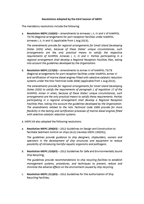
Resolutions Adopted by the 63rd Session of MEPCThe mandatory resolutions include the following:a.Resolution MEPC.216(63)– Amendments to Annexes I, II, IV and V of MARPOL73/78 (Regional arrangements for port reception facilities under MARPOLAnnexes I, II, IV and V) (applicable from 1 Aug 2013);The amendments provide for regional arrangements for Small Island Developing States (SIDS) when, because of these States' unique circumstances, such arrangements are the only practical means to satisfy the respective requirements of MARPOL Annexes I, II, IV and V. Parties participating in a regional arrangement shall develop a Regional Reception Facilities Plan, taking into account the guidelines developed by the Organization.b.Resolution MEPC.217(63)– Amendments to Annex VI of MARPOL 73/78(Regional arrangements for port reception facilities under MARPOL Annex VIand certification of marine diesel engines fitted with selective catalytic reduction systems under the NOx Technical Code 2008) (applicable from 1 Aug 2013);The amendments provide for regional arrangements for Small Island Developing States (SIDS) to satisfy the requirements of paragraph 1 of regulation 17 of the MARPOL Annex VI when, because of these States' unique circumstances, such arrangements are the only practical means to satisfy these requirements. Parties participating in a regional arrangement shall develop a Regional Reception Facilities Plan, taking into account the guidelines developed by the Organization.The amendments related to the NOx Technical Code 2008 provide for more flexibility in the testing and certification processes of marine diesel engines fitted with selective catalytic reduction systems.4. MEPC 63 also adopted the following resolutions:a.Resolution MEPC.209(63)– 2012 Guidelines on Design and Construction tofacilitate Sediment Control on ships (G12) (revokes MEPC.150(55));The guidelines provide guidance to ship designers, shipbuilders, owners and operators in the development of ship structures and equipment to reduce possibility of introducing harmful aquatic organisms and pathogens.b.Resolution MEPC.210(63)– 2012 Guidelines for Safe and Environmentally SoundShip Recycling;The guidelines provide recommendations to ship recycling facilities to establish management systems, procedures, and techniques to prevent, reduce and minimise the adverse effects on the environment caused by ship recycling.c.Resolution MEPC.211(63)– 2012 Guidelines for the Authorization of ShipRecycling Facilities;The guidelines provide recommendations for Parties on establishing mechanisms for authorising ship recycling facilities in accordance with requirements of the Ship Recycling Convention.d.Resolution MEPC.212(63)– 2012 Guidelines on the method of calculation of theAttained Energy Efficiency Design Index (EEDI) for new ships(revokesMEPC.1/Circ.681);The amendments to MARPOL Annex VI to include a new chapter 4 on theregulations on energy efficiency for ships are expected to enter into force on1 January 2013. The guidelines provide the method of calculation for theAttained EEDI as required under Regulation 20 of the new chapter and shall be followed.e.Resolution MEPC.213(63)– 2012 Guidelines for the Development of a ShipEnergy Efficiency Management Plan (SEEMP) (revokes MEPC.1/Circ.683);Regulation 22 of the new chapter 4 for regulations on energy efficiency for ships under MARPOL Annex VI requires each ship to keep onboard a ship specific Ship Energy Efficiency Management Plan (SEEMP). The guidelines provide assistance for development of the SEEMP and shall be taken into consideration by ships’ masters, operators and owners for the development.f.Resolution MEPC.214(63)– 2012 Guidelines on Survey and Certificationof theEnergy Efficiency Design Index (EEDI) (revokes MEPC.1/Circ.682);The purpose of the guidelines is to assist Administrations and Recognised Organisations in conducting the survey and certification of the EEDI and assist shipowners, shipbuilders and manufacturers related to the energy efficiency of ships to understand such procedures.g.Resolution MEPC.215(63)– Guidelines for Calculation of Reference Lines for usewith the Energy Efficiency Design Index (EEDI);Regulation 21 of the new chapter 4 for regulations on energy efficiency for ships under MARPOL Annex VI requires reference line to be established for each ship type to which the regulation is applicable. The guidelines provide the calculation method for the reference line and shall be followed.h.Resolution MEPC.218(63)– Development of Technical Onboard Equipment inrelation to the Designation of the Baltic Sea as a Special Area under MARPOLAnnex IV (for information);The resolution calls for the development of proven, adequate and costeffective technical onboard equipment, such as sewage treatment plants, to meet the discharge standards for passenger ships within a Special Area under MARPOL Annex IV.i.Resolution MEPC.219(63)– 2012 Guidelines for Implementation of MARPOLAnnex V (revokes MEPC.59(33), as amended by MEPC.92(45));The revised MARPOL Annex V is expected to enter into force on 1 January 2013.The guidelines provide guidance to the industry for implementing the requirements of the revised MARPOL Annex V and shall be followed.j.Resolution MEPC.220(63)– 2012 Guidelines for the Development of Garbage Management Plans (revokes MEPC.71(38));Regulation 10.2 of the revised MARPOL Annex V requires applicable ships to carry a Garbage Management Plan. The guidelines are intended to assist the shipowner/operator in the development of such a plan and shall be applied.k.Resolution MEPC.221(63)– 2012 Guidelines for the Development of a Regional Reception Facilities Plan (for information).The guidelines provide guidance for the development of a regional reception facilities plan (RRFP) to assist Member States in specific geographical regions of the world in the effective implementation of regional arrangements for port reception facilities.。
船舶未经处理生活污水排放速率标准_计算书-CCS中英文对照版
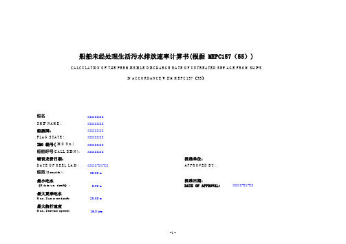
20.00 m5.00 m20.00 m16.0 kts最大夏季吃水Max. Summer draft:IMO 编号( IMO No.)SHIP NAME:XXXXXXX XXXXXXX 最小吃水(Minimum draft ):船宽( Breadth):船舶呼号(CALL SIGN):铺设龙骨日期:船名XXXXXXX 船舶未经处理生活污水排放速率计算书(根据 MEPC157(55))CALCULATION OF THE PERMISSIBLE DISCHARGE RATE OF UNTREATED SEWAGE FROM SHIPSIN ACCORDANCE WITH MEPC157(55)船旗国:FLAG STATE:XXXXXXX XXXXXXX 批准单位:APPROVED BY:批准日期:DATE OF APPROVAL:XXXXXXXDATE OF KEEL LAID:XXXX-XX-XX 最大航行速度Max. Service speed:XXXX-XX-XX1. 说明 Introduction:a) 根据经MEPC.164(56)决议修订的《73/78 防污公约》附则IV 第11.1.1 条的规定:“船舶在距最近陆地3 海里以外,使用主管机关按照本附则第9.1.2 条所认可的设备,排放业经粉碎和消毒的生活污水,或在距最近陆地12 海里以外排放未经粉碎或消毒的生活污水。
但不论哪种情况,不得将集污舱中储存的生活污水,或来自装有活动物处所的生活污水即刻排光,而应在船舶以不低于4 节的航速航行时,以适当的速率排放;排放速率应经主管机关根据本组织制订的标准予以认可。
”According to MARPOL ANNEX IV Regulation11.1.1with amendment by MEPC.164(56)(Discharge of sewage)“the ship is discharging comminuted and disinfected sewage using a system approved by the Administration in accordance with regulation9.1.2of this Annex at a distance of more than3nautical miles from the nearest land,or sewage which is not comminuted or disinfected,at a distance of more than12nautical miles from the nearest land,provided that, in any case,the sewage that has been stored in holding tanks,or sewage originating from spaces containing living animals,shall not be discharged instantaneously but at a moderate rate when the ship is en route and proceeding at not less than4knots;the rate of discharge shall beapproved by the Administration based upon standards developed by the Organization;.b) 本组织制订的标准系指由国际海事组织MEPC.157(55)号决议通过的“船舶排放未经处理的生活污水的速率标准的建议”。
MEPC_141_54_Fuel_Tank_Protection 燃油舱保护

MEPC 54/21ANNEX 2RESOLUTION MEPC.141(54)Adopted on 24 March 2006AMENDMENTS TO THE ANNEX OF THE PROTOCOL OF 1978 RELATING TO THE INTERNATIONAL CONVENTION FOR THE PREVENTION OFPOLLUTION FROM SHIPS, 1973(Amendments to regulation 1, addition to regulation 12A, consequential amendments to the IOPP Certificate and amendments to regulation 21 of the revisedAnnex I of MARPOL 73/78)THE MARINE ENVIRONMENT PROTECTION COMMITTEE,RECALLING article 38(a) of the Convention on the International Maritime Organization concerning the functions of the Marine Environment Protection Committee (the Committee) conferred upon it by international conventions for the prevention and control of marine pollution, NOTING article 16 of the International Convention for the Prevention of Pollution from Ships, 1973 (hereinafter referred to as the “1973 Convention”) and article VI of the Protocol of 1978 relating to the International Convention for the Prevention of Pollution from Ships, 1973 (hereinafter referred to as the “1978 Protocol”) which together specify the amendment procedure of the 1978 Protocol and confer upon the appropriate body of the Organization the function of considering and adopting amendments to the 1973 Convention, as modified by the 1978 Protocol (MARPOL 73/78),NOTING ALSO that the revised Annex I to MARPOL 73/78 was adopted by resolution MEPC.117(52) and is expected to enter into force on 1 January 2007,HAVING CONSIDERED proposed amendments to regulation 1, proposed new regulation 12A, consequential amendments to the Supplement (Forms A and B) of the IOPP Certificate, and proposed amendments to regulation 21 of the revised Annex I to MARPOL 73/78,1. ADOPTS, in accordance with article 16(2)(d) of the 1973 Convention, the amendments to the revised Annex I of MARPOL 73/78, the text of which is set out at Annex to the present resolution;2. DETERMINES, in accordance with article 16(2)(f)(iii) of the 1973 Convention, that the amendments shall be deemed to have been accepted on 1 February 2007, unless prior to that date, not less than one-third of the Parties or Parties the combined merchant fleets of which constitute not less than 50 per cent of the gross tonnage of the world’s merchant fleet, have communicated to the Organization their objection to the amendments;3. INVITES the Parties to note that, in accordance with article 16(2)(g)(ii) of the 1973 Convention, the said amendments shall enter into force on 1 August 2007 upon their acceptance in accordance with paragraph 2 above;MEPC 54/21ANNEX 2Page 24. REQUESTS the Secretary-General, in conformity with article 16(2)(e) of the 1973 Convention, to transmit to all Parties to MARPOL 73/78 certified copies of the present resolution and the text of the amendments contained in the Annex; and5. REQUESTS FURTHER the Secretary-General to transmit to the Members of the Organization which are not Parties to MARPOL 73/78 copies of the present resolution and its Annex.MEPC 54/21ANNEX 2Page 3ANNEXAMENDMENTS TO THE REVISED MARPOL ANNEX I1 Addition of paragraph 28.9 to regulation 1The following new paragraph 28.9 is added after the existing paragraph 28.8 of regulation 1:“28.9 ship delivered on or after 1 August 2010 means a ship:.1 for which the building contract is placed on or after 1 August 2007; or.2 in the absence of a building contract, the keels of which are laid or which are at a similar stage of construction on or after 1 February 2008; or .3 the delivery of which is on or after 1 August 2010; or.4 which have undergone a major conversion:.1 for which the contract is placed after 1 August 2007; or.2 in the absence of contract, the construction work of which is begunafter 1 February 2008; or.3 which is completed after 1 August 2010.”2 Addition of new regulation 12A on oil fuel tank protectionThe following new regulation 12A is added after the existing regulation 12:“Regulation 12A – Oil fuel tank protection1 This regulation shall apply to all ships with an aggregate oil fuel capacity of 600 m3 and above which are delivered on or after 1 August 2010, as defined in regulation 1.28.9 of this Annex.2 The application of this regulation in determining the location of tanks used to carry oil fuel does not govern over the provisions of regulation 19 of this Annex.3 For the purpose of this regulation, the following definitions shall apply:.1 “Oil fuel” means any oil used as fuel oil in connection with the propulsion and auxiliary machinery of the ship in which such oil is carried..2 “Load line draught (d S)” is the vertical distance, in metres, from the moulded baseline at mid-length to the waterline corresponding to the summer freeboarddraught to be assigned to the ship.MEPC 54/21ANNEX 2Page 4.3 “Light ship draught” is the moulded draught amidships corresponding to the lightweight..4 “Partial load line draught (d P)” is the light ship draught plus 60% of the difference between the light ship draught and the load line draught d S. The partial load linedraught (d p) shall be measured in metres.(d B)” is the vertical distance, in metres, from the moulded baseline at.5 “Waterlinemid-length to the waterline corresponding to 30% of the depth D S.(B S)” is the greatest moulded breadth of the ship, in metres, at or below.6 “Breadththe deepest load line draught (d S).(B B)” is the greatest moulded breadth of the ship, in metres, at or below.7 “Breadththe waterline (d B).(D S)” is the moulded depth, in metres, measured at mid-length to the.8 “Depthupper deck at side. For the purpose of the application, “upper deck” means thehighest deck to which the watertight transverse bulkheads except aft peakbulkheads extend..9 “Length (L)” means 96% of the total length on a waterline at 85% of the least moulded depth measured from the top of the keel, or the length from the foresideof the stem to the axis of the rudder stock on that waterline, if that be greater.In ships designed with a rake of keel the waterline on which this length ismeasured shall be parallel to the designed waterline. The length (L) shall bemeasured in metres..10 “Breadth (B)” means the maximum breadth of the ship, in metres, measured amidships to the moulded line of the frame in a ship with a metal shell and to theouter surface of the hull in a ship with a shell of any other material..11 “Oil fuel tank” means a tank in which oil fuel is carried, but excludes those tanks which would not contain oil fuel in normal operation, such as overflow tanks..12 “Small oil fuel tank” is an oil fuel tank with a maximum individual capacity not greater than 30 m3..13 “C” is the ship’s total volume of oil fuel, including that of the small oil fuel tanks, in m3, at 98% tank filling..14 “Oil fuel capacity” means the volume of a tank in m3, at 98% filling.4 The provisions of this regulation shall apply to all oil fuel tanks except small oil fuel tanks, as defined in 3.12, provided that the aggregate capacity of such excluded tanks is not greater than 600 m3.5 Individual oil fuel tanks shall not have a capacity of over 2,500 m3.MEPC 54/21ANNEX 2Page 5 6 For ships, other than self-elevating drilling units, having an aggregate oil fuel capacity of 600 m3 and above, oil fuel tanks shall be located above the moulded line of the bottom shell plating nowhere less than the distance h as specified below:h = B/20 m or,h = 2.0 m, whichever is the lesser.The minimum value of h = 0.76 mIn the turn of the bilge area and at locations without a clearly defined turn of the bilge, the oil fuel tank boundary line shall run parallel to the line of the midship flat bottom as shown in Figure 1.Figure 1 – Oil fuel tank boundary lines for the purpose of paragraph 67 For ships having an aggregate oil fuel capacity of 600 m3 or more but less than 5,000 m3, oil fuel tanks shall be located inboard of the moulded line of the side shell plating, nowhere less than the distance w which, as shown in Figure 2, is measured at any cross-section at right angles to the side shell, as specified below:w = 0.4 + 2.4 C/20,000 mThe minimum value of w = 1.0 m, however for individual tanks with an oil fuel capacity of less than 500 m3 the minimum value is 0.76 m.8 For ships having an aggregate oil fuel capacity of 5,000 m3 and over, oil fuel tanks shall be located inboard of the moulded line of the side shell plating, nowhere less than the distance w which, as shown in Figure 2, is measured at any cross-section at right angles to the side shell, as specified below:w = 0.5 + C/20,000 m orw = 2.0 m, whichever is the lesser.MEPC 54/21ANNEX 2Page 6Figure 2 – Oil fuel tank boundary lines for the purpose of paragraphs 7 and 89 Lines of oil fuel piping located at a distance from the ship’s bottom of less than h,as defined in paragraph 6, or from the ship’s side less than w, as defined in paragraphs 7 and 8 shall be fitted with valves or similar closing devices within or immediately adjacent to the oil fuel tank. These valves shall be capable of being brought into operation from a readily accessible enclosed space the location of which is accessible from the navigation bridge or propulsion machinery control position without traversing exposed freeboard or superstructure decks. The valves shall close in case of remote control system failure (fail in a closed position) and shall be kept closed at sea at any time when the tank contains oil fuel except that they may be opened during oil fuel transfer operations.10 Suction wells in oil fuel tanks may protrude into the double bottom below the boundary line defined by the distance h provided that such wells are as small as practicable and the distance between the well bottom and the bottom shell plating is not less than 0.5 h.11 Alternatively to paragraphs 6 and either 7 or 8, ships shall comply with the accidental oil fuel outflow performance standard specified below:.1 The level of protection against oil fuel pollution in the event of collision or grounding shall be assessed on the basis of the mean oil outflow parameter asfollows:O M < 0.0157-1.14E-6·C 600 m3≤ C < 5,000 m3O M < 0.010 C ≥ 5,000 m3Where O M = mean oil outflow parameter;C = total oil fuel volume..2 The following general assumption shall apply when calculating the mean oil outflow parameter:.1 the ship shall be assumed loaded to the partial load line draught d withoutMEPC 54/21ANNEX 2Page 7 .2 all oil fuel tanks shall be assumed loaded to 98% of their volumetric capacity;.3 the nominal density of the oil fuel (ρn) shall generally be taken as 1,000 kg/m3. If the density of the oil fuel is specifically restricted to alesser value, the lesser value may be applied; and.4 for the purpose of these outflow calculations, the permeability of each oil fuel tank shall be taken as 0.99, unless proven otherwise..3 The following assumptions shall be used when combining the oil outflow parameters:.1 The mean oil outflow shall be calculated independently for side damage and for bottom damage and then combined into a non-dimensional oiloutflow parameter O M, as follows:O M = (0.4 O MS + 0.6 O MB) / Cwhere:O MS = mean outflow for side damage, in m3O MB = mean outflow for bottom damage, in m3C = total oil fuel volume..2 For bottom damage, independent calculations for mean outflow shall be done for 0 m and 2.5 m tide conditions, and then combined as follows:O MB = 0.7 O MB(0) + 0.3 O MB(2.5)where:O MB(0) = mean outflow for 0 m tide condition, andO MB(2.5) = mean outflow for minus 2.5 m tide condition, in m3. .4 The mean outflow for side damage O MS shall be calculated as follows:P S(i) O S(i) [m3]O MS = ∑n1where:i = represents each oil fuel tank under consideration;n = total number of oil fuel tanks;P S(i)= the probability of penetrating oil fuel tank i from side damage,calculated in accordance with paragraph 11.6 of this regulation;O S(i)= the outflow, in m3, from side damage to oil fuel tank i, which isassumed equal to the total volume in oil fuel tank i at 98%filling..5 The mean outflow for bottom damage shall be calculated for each tidal conditionMEPC 54/21ANNEX 2Page 8P B(i) O B(i) C DB(i) [m3].1 O MB(0) = ∑n1where:i = represents each oil fuel tank under consideration;n = total number of oil fuel tanks;P B(i)= the probability of penetrating oil fuel tank i from bottomdamage, calculated in accordance with paragraph 11.7of this regulation;O B(i)=the outflow from oil fuel tank i, in m3, calculated inaccordance with paragraph 11.5.3 of this regulation; andC DB(i) factor to account for oil capture as defined inparagraph 11.5.4..2 O MB(2.5) = ∑nP B(i) O B(i) C DB(i)[m3]1where:i, n, P B(i) and C DB(i)= as defined in subparagraph .1 aboveO B(i)=the outflow from oil fuel tank i, in m3,after tidal change..3 The oil outflow O B(i) for each oil fuel tank shall be calculated based on pressure balance principles, in accordance with the following assumptions:.1 The ship shall be assumed stranded with zero trim and heel, withthe stranded draught prior to tidal change equal to the partial loadline draught d P..2 The oil fuel level after damage shall be calculated as follows:h F = {(d P + t C – Z l)(ρS) }/ρnwhere: h F = the height of the oil fuel surface above Z l, in m;t C= the tidal change, in m. Reductions in tide shall beexpressed as negative values;Z l=the height of the lowest point in the oil fuel tankabove the baseline, in m;ρS= density of seawater, to be taken as 1,025 kg/m3; and,ρn= nominal density of the oil fuel, as defined in 11.2.3..3 The oil outflow O B(i) for any tank bounding the bottom shell platingshall be taken not less than the following formula, but no more thanthe tank capacity:O B(i) = H W . AMEPC 54/21ANNEX 2Page 9where:H W = 1.0 m, when Y B = 0H W = B B /50 but not greater than 0.4 m, when Y B is greaterthan B B /5 or 11.5 m, whichever is less“H W ” is to be measured upwards from the midship flatbottom line. In the turn of the bilge area and at locationswithout a clearly defined turn of the bilge, H W is to bemeasured from a line parallel to the midship flat bottom, asshown for distance “h” in Figure 1.For Y B values outboard B B /5 or 11.5 m, whichever is less, H W is tobe linearly interpolated.Y B = the minimum value of Y B over the length of the oilfuel tank, where at any given location, Y B is thetransverse distance between the side shell atwaterline d B and the tank at or below waterline d B .A = the maximum horizontal projected area of the oilfuel tank up to the level of H W from the bottom ofthe tank.Figure 3 – Dimensions for calculation of the minimum oil outflow for the purpose ofsubparagraph 11.5.3.3 Centre LineB B /5 or 11.5m, whichever is less(measured inboard from the ship’s side atright angles to the centreline at the levelof d B )H w = B B /50 but not greaterthan 0.40mMEPC 54/21ANNEX 2Page 10.4 In the case of bottom damage, a portion from the outflow from anoil fuel tank may be captured by non-oil compartments. This effectis approximated by application of the factor C DB(i) for each tank,which shall be taken as follows:C DB(i) =0.6 for oil fuel tanks bounded from below by non-oilcompartments;C DB(i) = 1 otherwise..6 The probability P S of breaching a compartment from side damage shall be calculated as follows:.1 P S = P SL . P SV . P STP SL = (1 – P Sf – P Sa) = probability the damage will extend into the where:longitudinal zone bounded by X a and X f;P SV = (1 – P Su – P Sl) = probability the damage will extend into thevertical zone bounded by Z l and Z u;P ST = (1 – P Sy) = probability the damage will extend transverselybeyond the boundary defined by y;.2 P Sa, P Sf, P Su and P Sl shall be determined by linear interpolation from the table of probabilities for side damage provided in 11.6.3, and P Sy shall becalculated from the formulas provided in 11.6.3, where:P Sa = the probability the damage will lie entirely aft of location X a/L;P Sf= the probability the damage will lie entirely forward of locationX f/L;P Sl = probability the damage will lie entirely below the tank;P Su = probability the damage will lie entirely above the tank; andP Sy = probability the damage will lie entirely outboard the tank.Compartment boundaries X a, X f, Z l, Z u and y shall be developed as follows:X a = the longitudinal distance from aft terminal of L to the aft mostpoint on the compartment being considered, in m;X f = the longitudinal distance from aft terminal of L to the foremostpoint on the compartment being considered, in m;Z l =the vertical distance from the moulded baseline to the lowestpoint on the compartment being considered, in m. Where Z l isgreater than D S, Z l shall be taken as D S;Z u = the vertical distance from the moulded baseline to the highestpoint on the compartment being considered, in m. Where Z u isgreater than D S, Z u shall be taken as D S; and,MEPC 54/21ANNEX 2Page 11y =the minimum horizontal distance measured at right angles tothe centreline between the compartment under considerationand the side shell, in m1.In way of the turn of the bilge, y need not to be considered below adistance h above baseline, where h is lesser of B/10, 3 m or the top ofthe tank..3 Table of Probabilities for side damageX a/L P Sa X f/L P Sf Z l/D S P Sl Z u/D S P Su0,00 0,000 0,00 0,967 0,00 0,000 0,00 0,9680,05 0,023 0,05 0,917 0,05 0,000 0,05 0,9520,10 0,068 0,10 0,867 0,10 0,001 0,10 0,9310,15 0,117 0,15 0,817 0,15 0,003 0,15 0,9050,20 0,167 0,20 0,767 0,20 0,007 0,20 0,8730,25 0,217 0,25 0,717 0,25 0,013 0,25 0,8360,30 0,267 0,30 0,667 0,30 0,021 0,30 0,7890,35 0,317 0,35 0,617 0,35 0,034 0,35 0,7330,40 0,367 0,40 0,567 0,40 0,055 0,40 0,6700,45 0,417 0,45 0,517 0,45 0,085 0,45 0,5990,50 0,467 0,50 0,467 0,50 0,123 0,50 0,5250,55 0,517 0,55 0,417 0,55 0,172 0,55 0,4520,60 0,567 0,60 0,367 0,60 0,226 0,60 0,3830,65 0,617 0,65 0,317 0,65 0,285 0,65 0,3170,70 0,667 0,70 0,267 0,70 0,347 0,70 0,2550,75 0,717 0,75 0,217 0,75 0,413 0,75 0,1970,80 0,767 0,80 0,167 0,80 0,482 0,80 0,1430,85 0,817 0,85 0,117 0,85 0,553 0,85 0,0920,90 0,867 0,90 0,068 0,90 0,626 0,90 0,0460,95 0,917 0,95 0,023 0,95 0,700 0,95 0,0131,00 0,967 1,00 0,000 1,00 0,775 1,00 0,000P Sy shall be calculated as follows:y/B S≤ 0.05P Sy = (24.96 – 199.6 y/B S) (y/B S) forP Sy = 0.749 + {5 – 44.4 (y/B S – 0.05)} {(y/B S) – 0.05} for 0.05 < y/B S < 0.1P Sy = 0.888 + 0.56 ( y/B S -0.1) for y/B S≥ 0.1P Sy is not to be taken greater than 1..7 The probability P B of breaching a compartment from bottom damage shall be calculated as follows:1For symmetrical tank arrangements, damages are considered for one side of the ship only, in which case all “y”dimensions are to be measured from that side. For asymmetrical arrangements reference is made to the Explanatory Notes on matters related to the accidental oil outflow performance, adopted by the Organization by resolution MEPC.122(52).MEPC 54/21 ANNEX 2 Page 12.1 P B = P BL . P BT . P BVwhere: P BL = (1 – P Bf – P Ba ) = probability the damage will extend into thelongitudinal zone bounded by X a and X f ;P BT = (1 – P Bp – P Bs ) = probability the damage will extend intotransverse zone bounded by Y p and Y s ; andP BV = (1 – P Bz ) = probability the damage will extend verticallyabove the boundary defined by z;.2 P Ba , P Bf , P Bp and P Bs shall be determined by linear interpolation from thetable of probabilities for bottom damage provided in 11.7.3, and P Bz shall be calculated from the formulas provided in 11.7.3, where:P Ba = the probability the damage will lie entirely aft of locationX a /L;P Bf = the probability the damage will lie entirely forward oflocation X f /L;P Bp = probability the damage will lie entirely to port of the tank; P Bs = probability the damage will lie entirely to starboard thetank; andP Bz = probability the damage will lie entirely below the tank.Compartment boundaries X a, X f, Y p, Y s and z shall be developed as follows:X a and X f as defined in 11.6.2;Y p = the transverse distance from the port-most point on thecompartment located at or below the waterline d B , to a vertical plane located B B /2 to starboard of the ship’s centreline;Y s = the transverse distance from the starboard-most point on thecompartment located at or below the waterline d B , to a vertical plane located B B /2 to starboard of the ship’s centreline; and z = the minimum value of z over the length of thecompartment, where, at any given longitudinal location, z is the vertical distance from the lower point of the bottom shell at that longitudinal location to the lower point of the compartment at that longitudinal location.MEPC 54/21ANNEX 2Page 13 .3 Table of probabilities for bottom damageX a/L P Ba X f/L P Bf Y p/B B P Bp Y s/B B P Bs0,00 0,000 0,00 0,969 0,00 0,844 0,00 0,0000,05 0,002 0,05 0,953 0,05 0,794 0,05 0,0090,10 0,008 0,10 0,936 0,10 0,744 0,10 0,0320,15 0,017 0,15 0,916 0,15 0,694 0,15 0,0630,20 0,029 0,20 0,894 0,20 0,644 0,20 0,0970,25 0,042 0,25 0,870 0,25 0,594 0,25 0,1330,30 0,058 0,30 0,842 0,30 0,544 0,30 0,1710,35 0,076 0,35 0,810 0,35 0,494 0,35 0,2110,40 0,096 0,40 0,775 0,40 0,444 0,40 0,2530,45 0,119 0,45 0,734 0,45 0,394 0,45 0,2970,50 0,143 0,50 0,687 0,50 0,344 0,50 0,3440,55 0,171 0,55 0,630 0,55 0,297 0,55 0,3940,60 0,203 0,60 0,563 0,60 0,253 0,60 0,4440,65 0,242 0,65 0,489 0,65 0,211 0,65 0,4940,70 0,289 0,70 0,413 0,70 0,171 0,70 0,5440,75 0,344 0,75 0,333 0,75 0,133 0,75 0,5940,80 0,409 0,80 0,252 0,80 0,097 0,80 0,6440,85 0,482 0,85 0,170 0,85 0,063 0,85 0,6940,90 0,565 0,90 0,089 0,90 0,032 0,90 0,7440,95 0,658 0,95 0,026 0,95 0,009 0,95 0,7941,00 0,761 1,00 0,000 1,00 0,000 1,00 0,844P Bz shall be calculated as follows:z/D S≤ 0.1P Bz = (14.5 – 67 z/D S) (z/D S) forP Bz = 0.78 + 1.1 {(z/D S -0.1)} for z/D S > 0.1P Bz is not to be taken greater than 1..8 For the purpose of maintenance and inspection, any oil fuel tanks that do not border the outer shell plating shall be located no closer to the bottom shell platingthan the minimum value of h in paragraph 6 and no closer to the side shell platingthan the applicable minimum value of w in paragraph 7 or 8.12 In approving the design and construction of ships to be built in accordance with this regulation, Administrations shall have due regard to the general safety aspects, including the need for maintenance and inspection of wing and double bottom tanks or spaces.”3 Consequential amendments to the Supplement of the IOPP Certificate (Forms Aand B)The following new paragraph 2A is added to the Supplement of the IOPP Certificate (Forms A and B):“2A.1 The ship is required to be constructed according to regulation 12A and complies with the requirements of:MEPC 54/21ANNEX 2Page 14paragraphs 6 and either 7 or 8 (double hull construction) □paragraph 11 (accidental oil fuel outflow performance). □2A.2 The ship is not required to comply with the requirements ofregulation 12A.□ ”4 Amendments to regulation 21The text of existing paragraph 2.2 of regulation 21 on Prevention of oil pollution from oil tankers carrying heavy grade oil as cargo is replaced by the following:“oils, other than crude oils, having either a density at 15ºC higher than 900 kg/m3 or a kinematic viscosity at 50ºC higher than 180 mm2/s; or”***MEPC 54/21ANNEX 3RESOLUTION MEPC.142(54)Adopted on 24 March 2006AMENDMENTS TO THE GUIDELINES FOR THE APPLICATION OF THE REVISED MARPOL ANNEX I REQUIREMENTS TO FLOATING PRODUCTION, STORAGE AND OFFLOADING FACILITIES (FPSOs) AND FLOATING STORAGE UNITS (FSUs)(Resolution MEPC.139(53))THE MARINE ENVIRONMENT PROTECTION COMMITTEE,RECALLING Article 38(a) of the Convention on the International Maritime Organization concerning the functions of the Marine Environment Protection Committee (the Committee) conferred upon it by international conventions for the prevention and control of marine pollution, NOTING resolution MEPC.139(53) by which the Committee adopted Guidelines for the application of the revised MARPOL Annex I requirements to Floating Production, Storage and Offloading facilities (FPSOs) and Floating Storage Units (FSUs),HAVING CONSIDERED proposed amendments to the Guidelines concerning the applicability of new regulation 12A of MARPOL Annex I on oil fuel tank protection to FPSOs and FSUs,1. ADOPTS the Amendments to the Guidelines for the application of the revised MARPOL Annex I requirements to Floating Production, Storage and Offloading facilities (FPSOs) and Floating Storage Units (FSUs), the text of which is set out in the Annex to the present resolution; and2. INVITES Member Governments to give due consideration to the Guidelines, as amended, when implementing the requirements prescribed in regulation 12A of the revised MARPOL Annex I.MEPC 54/21ANNEX 3Page 2ANNEX1 The table in annex 1 to the Guidelines for the application of the revised MARPOL Annex I requirements to FPSOs and FSUs is amended as follows:.1 Insert an additional row below regulation 12 as follows:12A Oil fuel tank protection Applies to new purpose builtFPSOs and FSUs onlyexcluding the requirements ofparagraph 6. However, whenundertaking any voyage awayfrom the operating station forwhatever purpose, the doublebottom oil fuel tanks are to beempty unless they are incompliance with therequirements of paragraph 6..2 Amend row relating to regulation 37 to read as follows:37.1 – 37.3 SOPEP Applies in respect ofSOPEP. However, contingencyplan in accordance withrequirements of OPRC Art 3(2)may be accepted under UI 48 asmeeting this requirement. Insuch cases a separate SOPEP inaccordance with the MARPOLformat is not required. Thisacceptance of the contingencyplan does not apply to adisconnectable FPSO/FSUunless that plan remainsapplicable when the FPSO/FSUis not connected to the riser..3 Insert an additional row below regulation 37 as follows:37.4 Access to stability andApplicableresidual strength calculationprogrammesMEPC54/21ANNEX 3Page 32 In the record of construction and equipment for FPSOs and FSUs, new section 3A isadded as follows:“3A. Oil fuel tank protection (regulation 12A)3A.1 The ship is required to be constructed according to regulation 12A and complieswith the requirements of:paragraph 7 or 8 (double side construction) □paragraphs 6 and either 7 or 8 (double hull construction) □paragraph 11 (accidental oil fuel outflow performance). □3A.2 The ship is not required to comply with the requirements ofregulation 12A.□ ”***。
MEPC 240(65)

11 In paragraph 6.8.2, the references "regulation 9(1)(a)(iv) and (v)" are replaced by the references "regulation 31.1.4 and 31.1.5".
I:\MEPC\65\22-Add-1.doc
13 In the footnote associated with subparagraph 6.12.2, the reference "regulation 9(1)(a)(5)" is replaced by the reference "regulation 34.1.5". 14 In paragraph 7.2.2, after the words "white products", insert the words ", individual biofuel blends". 15 In subparagraph 8.3.3, the references "regulations 9(1)(a)(iv) and (v)" are replaced by the references "regulations 34.1.4 and 34.1.5". ANNEX, PART 1 – TEST AND PERFORMANCE SPECIFICATIONS FOR TYPE APPROVAL OF OIL CONTENT METERS 16 In the table under paragraph 1.2.6, under the column "Parameters Tolerance" and row "6", the text "RMG 35 Parameters as per ISO 8217:1996 (table 2)" is replaced by the following text: "RMG 35 Parameters as per ISO 8217:2010/Corr 1:2011 (tables 1 and 2)" 17 In paragraph 1.2.7, the reference standard "ISO 8217:1996 (table 1)" is replaced by the referenced standard "ISO 8217:2010/Corr 1:2011 (tables 1 and 2)". 18 New paragraph 1.2.8 is added, as follows: "1.2.8 If the meter is to be considered suitable for an individual biofuel blend containing 75 per cent or more of petroleum oil, it should also be tested against each such substance for which approval is required, in a manner similar to the tests set out in paragraphs 1.2.5 and 1.2.6. The high shear pump shown in figure 1 should be kept in operation at high speed during this test to assist in dissolving the appropriate fraction of the substance in the water stream." 19 New paragraph 1.2.9 is added, as follows: "1.2.9 Individual Biofuel blends should be tested at 75 per cent and 99 per cent petroleum oil." 20 The existing paragraphs 1.2.8 to 1.2.19 are renumbered as paragraphs 1.2.10 to 1.2.21.
MEPC.347(78)
ANNEX 9RESOLUTION MEPC.347(78)(adopted on 10 June 2022)GUIDELINES FOR THE VERIFICATION AND COMPANY AUDITS BY THE ADMINISTRATION OF PART III OF THE SHIP ENERGY EFFICIENCY MANAGEMENTPLAN (SEEMP)THE MARINE ENVIRONMENT PROTECTION COMMITTEE,RECALLING Article 38(a) of the Convention on the International Maritime Organization concerning the functions of the Marine Environment Protection Committee (the Committee) conferred upon it by international conventions for the prevention and control of marine pollution from ships,NOTING that the Committee adopted, at its seventy-sixth session, by resolution MEPC.328(76), the 2021 Revised MARPOL Annex VI which will enter into force on 1 November 2022,NOTING IN PARTICULAR that the 2021 Revised MARPOL Annex VI (MARPOL Annex VI) contains amendments concerning mandatory goal-based technical and operational measures to reduce carbon intensity of international shipping,NOTING FURTHER that regulation 26 of MARPOL Annex VI requires each ship to keep on board a Ship Energy Efficiency Management Plan (SEEMP), to be developed and reviewed, taking into account the guidelines adopted by the Organization,RECOGNIZING that the aforementioned amendments to MARPOL Annex VI require relevant guidelines for uniform and effective implementation of the regulations and to provide sufficient lead time for industry to prepare,HAVING CONSIDERED, at its seventy-eighth session, draft Guidelines for the verification and company audits by the Administration of part III of the Ship Energy Efficiency Management Plan (SEEMP),1 ADOPTS the Guidelines for the verification and company audits by the Administration of part III of the Ship Energy Efficiency Management Plan (SEEMP), as set out in the annex to the present resolution;2 INVITES Administrations to take the annexed Guidelines into account when developing and enacting national laws which give force to and implement requirements set forth in regulation 26 of MARPOL Annex VI;3 REQUESTS the Parties to MARPOL Annex VI and other Member Governments to bring the annexed Guidelines to the attention of masters, seafarers, shipowners, ship operators and any other interested parties;4 AGREES to keep the Guidelines under review in light of experience gained with their implementation, also taking into consideration that, in accordance with regulations 25.3 and 28.11 of MARPOL Annex VI, a review of the technical and operational measures to reduce carbon intensity of international shipping shall be completed by 1 January 2026.ANNEXGUIDELINES FOR THE VERIFICATION AND COMPANY AUDITS BY THE ADMINISTRATION OF PART III OF THE SHIP ENERGY EFFICIENCY MANAGEMENTPLAN (SEEMP)CONTENTS1 INTRODUCTION2 DEFINITIONS3 RESPONSIBILITIES4 VERIFICATION OF THE SEEMP AND DOCUMENTATION5 INITIAL, PERIODICAL, ADDITIONAL VERIFICATIONS AND COMPANY AUDITS6 ELEMENTS OF VERIFICATION7 COMBINATION WITH ISMANNEX – SAMPLE FORMAT FOR CONFIRMATION OF COMPLIANCE1 INTRODUCTION1.1 The Guidelines for the verification and company audits by the Administration of part III of the Ship Energy Efficiency Management Plan (SEEMP) have been developed to assist Administrations with carrying out the verifications and company audits required by regulation 26.3.3 of MARPOL Annex VI.1.2 The aim of these Guidelines is to:.1 provide guidance to Administrations to effectively and efficiently carry out verifications of, and company audits related to, the Ship Energy EfficiencyManagement Plan (SEEMP) to ensure compliance with regulation 26.3 andwith regulation 28 of MARPOL Annex VI; and.2 ensure that the SEEMP includes the relevant elements in accordance with regulation 26.3 of MARPOL Annex VI, as applicable, and that the SEEMP isreliable, while minimizing the costs and associated burdens to the ship andthe Administration.1.3 The verification of and the company audits related to the SEEMP may be carried out by the Administration or an organization recognized by it.11.4 It should be noted that the Organization has adopted separate 2022Guidelines for Administration verification of ship fuel oil consumption data and operational carbon intensity (resolution MEPC.348(78), adopted 10 June 2022).2 DEFINITIONSFor the purpose of these Guidelines, the definitions in MARPOL Annex VI apply.3 RESPONSIBILITIES3.1 The responsibilities of Administrations and ships are set out in MARPOL Annex VI. These Guidelines do not change those responsibilities or create any new obligations.3.2 An Administration may authorize an organization to carry out verifications of, and company audits related to, the SEEMP, and issue the Confirmation of Compliance, submit the data to the Organization and perform other actions authorized by the Administration. In every case, the Administration assumes full responsibility for all tasks conducted by the Administration, or any organization duly authorized by it (hereinafter referred to as "the Administration").3.3 Verification of, and company audits related to, the SEEMP do not relieve the company, management, those undertaking delegated SEEMP tasks, officers or seafarers of their obligations as to compliance with those requirements in regulation 28 of MARPOL Annex VI.3.4 The company is responsible for:.1 informing relevant personnel and those undertaking the delegated SEEMP tasks about the content of the SEEMP;1Refer to the Code for Recognized Organizations (RO Code), as adopted by the Organization by resolution MEPC.237(65), as may be amended by the Organization..2 appointing responsible members of staff to accompany the verifier; and.3 providing access and evidential materials as requested by the verifier.4 VERIFICATION OF THE SEEMP AND DOCUMENTATION4.1 To facilitate the verification, the Administration should indicate what documentation, if any, the company should submit along with its SEEMP.5 INITIAL, PERIODICAL, ADDITIONAL VERIFICATIONS AND COMPANY AUDITS 5.1 The verification and audit process for the SEEMP according to regulation 26.3.3 of MARPOL Annex VI should normally involve the following:.1 initial verification;.2 periodical verifications;.3 additional verifications; and.4 company audits.5.2 The initial, periodical, additional verifications and company audits should be based on documentary evidence.Initial verification (regulation 5.4.6 of MARPOL Annex VI)5.3 The Administration should perform an initial verification to ensure that for each ship to which regulation 26.3 of MARPOL Annex VI applies, the SEEMP complies with regulation 26.3.1 of MARPOL Annex VI. In accordance with regulation 5.4.6 of MARPOL Annex VI, this process must be done prior to 1 January 2023 for existing ships or before a new ship is put in service.5.4 On satisfactory assessment of the SEEMP part III, the Administration can issue the Confirmation of Compliance (sample format in the annex to this document).Periodical verification (regulation 5.4.6 of MARPOL Annex VI)5.5 If any of the elements in regulation 26.3.1 is updated, and in any case every three years, the Administration should perform a periodical verification to ensure the SEEMP complies with regulation 26.3.1 of MARPOL Annex VI in accordance with regulation 5.4.6 of MARPOL Annex VI.5.6 On satisfactory assessment of SEEMP part III, the Administration should issue the Confirmation of Compliance (sample format in the annex to this document).Additional verifications (regulation 6.8 of MARPOL Annex VI)5.7 The Administration should, in the case of a ship rated as D for three consecutive years or a ship rated as E, perform an additional verification to ensure that a plan of corrective actions has been established in accordance with regulations 28.7 and 28.8.5.8 On satisfactory verification of the plan of corrective actions, the Administration can issue the Statement of Compliance according to regulation6.8.Company audits5.9 The Administration should, in accordance with regulation 26.3.3, perform periodical company audits to:.1 verify that the SEEMP for which the Confirmation of Compliance has previously been issued complies with regulation 26.3.1 and, in the case ofnon-compliance, require remedial action;.2 confirm that the ship is being operated in accordance with SEEMP part III, regardless of its rating;.3 verify the progress made in the (corrective) actions to be taken in the execution of the three-year implementation plan and the plan of correctiveactions;.4 verify self-assessment and improvement of actions taken; and.5 verify the assignment of responsibilities related to the implementation and monitoring of measures.5.10 The periodical company audits may include annual audits of the company (company audits) and verifications on board the ship (shipboard audits).5.11 These additional shipboard verifications and company audits, if undertaken, should be six months after the issuance of the Statement of Compliance at the latest.6 ELEMENTS OF VERIFICATION6.1 Verification could consist of, but not be limited to, the following elements:.1 verification of the method of calculations of the CII and that there is a proper description of the method to report ship data to the Administration;.2 assessment of the effectiveness (of the combination) of measures, so that when implemented the ship will with reasonable assurance achieve therequired annual operational CII, including the goal as set in accordance withparagraph 4.1.7 and 9.7 of the SEEMP Guidelines; and.3 robustness of the three-year implementation plan and, where applicable, the plan of corrective actions, including whether realistic timelines forimplementation of actions have been included.7 COMBINATION WITH ISM AUDITS7.1 Verification of implementation aspects of the SEEMP on board (monitoring, self-evaluation and improvements, etc.) could be combined with the ISM audits.7.2 The verifications may be carried out in accordance with guidelines on implementation of the ISM Code referred to in Chapter 15 of the ISM Code.ANNEXSAMPLE FORMAT FOR CONFIRMATION OF COMPLIANCECONFIRMATION OF COMPLIANCE – SEEMP PART IIIIssued under the provisions of the Protocol of 1997, as amended, to amend the International Convention for the Prevention of Pollution from Ships, 1973, as modified by the Protocol of 1978 related thereto (hereinafter referred to as "the Convention") under the authority of the Government of:. . . . . . . . . . . . . . . . . . . . . . . . . . . . . . . . . . . . . . . . . . . . . . . . . . . . . . . . . . . . . . . . . . . . . . . . . .(full designation of the Country)by . . . . . . . . . . . . . . . . . . . . . . . . . . . . . . . . . . . . . . . . . . . . . . . . . . . . . . . . . . . . . . . . . . . . . . . . (full designation of the competent person or organization authorized under the provisions ofthe Convention)Particulars of ship*Name of ship . . . . . . . . . . . . . . . . . . . . . . . . . . . . . . . . . . . . . . . . . . . . . . . . . . . . . . . .Distinctive number or letters. . . . . . . . . . . . . . . . . . . . . . . . . . . . . . . . . . .. . . . . . . . . . .IMO number†. . . . . . . . . . . . . . . . . . . . . . . . . . . . . . . . . . . . . . . . . . . . . . . . . . . . . . .. .Port of registry . . . . . . . . . . . . . . . . . . . . . . . . . . . . . . . . . . . . . . . . . . . . . . . . . . . . . . .Gross tonnage. . . . . . . . . . . . . . . . . . . . . . . . . . . . . . . . . . . . . . . . . . . . . . . . . . . . . . . .SEEMP part III date of revision, as applicable . . . . . . . . . . . . . . . . . . . . . . . . . . . . . . . THIS IS TO CONFIRM:Taking into account the 2022 Guidelines for the development of a Ship Energy Efficiency Management Plan (SEEMP)adopted by resolution MEPC.346(78), the ship's SEEMP has been developed and complies with regulation 26.3.1 of Annex VI of the Convention.Issued at: . . . . . . . . . . . . . . . . . . . . . . . . . . . . . . . . . . . . . . . . . . . . . . . . . . . . . . . . . . . . . . . . .(place of issue of the Confirmation)Date (dd/mm/yyyy) . . . . . . . . . . . . . . . . . .. . . . . . . . . . . . . . . . . . . . . . . . . . .. .(date of issue) (signature of duly authorized officialissuing the Confirmation)(seal or stamp of the authority, as appropriate)*Alternatively, the particulars of the ship may be placed horizontally in boxes.†In accordance with the IMO Ship Identification Number Scheme, adopted by the Organization by resolution A.1117(30).***。
英语作文myresolution

英语作文myresolution英文回答:Embarking upon a transformative odyssey of self-improvement, I solemnly resolve to cultivate a harmonious symphony within my being, aligning my aspirations with the rhythms of growth and fulfillment. I pledge to awaken the latent potential that slumbers within me, igniting the flames of passion and determination that will propel me toward the horizon of my dreams.With unwavering resolve, I embark on a journey to cultivate a sanctuary of knowledge, expanding myintellectual horizons through voracious reading and seeking mentorship from those who have navigated similar paths before me. I will immerse myself in the tapestry of human thought, embracing diverse perspectives and challenging my own beliefs with an open mind. By nurturing my curiosity and fostering a thirst for lifelong learning, I aim to become a beacon of wisdom and a catalyst for positivechange in the world.Simultaneously, I recognize the profound significance of physical and emotional well-being. I vow to embark on a sacred pilgrimage to enhance my physicality and forge an unyielding spirit. Through disciplined exercise and a wholesome diet, I will build a strong foundation upon which to construct a life of vitality and purpose. I will cultivate mindfulness and meditation practices to calm the tumultuous waters of my mind, fostering inner peace and clarity. By nurturing my body and mind as interconnected vessels of potential, I aspire to radiate an aura of health and well-being, inspiring others to prioritize their own holistic growth.Furthermore, I pledge to weave the threads of compassion and empathy into the fabric of my interactions.I will strive to see the world through the eyes of others, understanding their unique perspectives and offering empathy to those who may be struggling. I will extend a helping hand to those in need, whether it be through volunteering my time or simply offering a listening ear. Bycultivating a heart that beats with compassion, I hope to foster a ripple effect of kindness throughout my community and beyond.In addition to these personal transformations, I am deeply committed to making a meaningful contribution to the world around me. I believe that every individual has the potential to ignite positive change, and I resolve to harness my passions and talents to create a more just and equitable society. I will actively seek opportunities to advocate for the marginalized, fight against injustice, and promote sustainable practices that protect our planet for future generations. By embodying these values in my daily actions, I aim to leave a legacy that extends far beyond my own lifetime.As I embark on this transformative journey, I am filled with a profound sense of gratitude for the countless individuals who have supported and inspired me along the way. Their guidance, encouragement, and unwavering beliefin my potential have fueled my determination to reach for the stars. I am eternally indebted to these beacons oflight who have illuminated my path and empowered me to become the best version of myself.With unwavering faith in my ability to manifest my resolutions into reality, I pen my name below as a testament to my enduring commitment to this profound journey of self-transformation. May the universe bear witness to my heartfelt aspirations and guide me toward the fulfillment of my highest potential.中文回答:我的决心。
resolution英文作文

resolution英文作文英文:Resolution is a powerful tool that helps me achieve my goals and make positive changes in my life. Setting a resolution gives me a clear direction and a sense of purpose. It motivates me to take action and stay focused on what I want to accomplish.For example, last year my resolution was to improve my physical fitness. I set a goal to exercise at least three times a week and to eat a healthier diet. I also joined a gym and hired a personal trainer to help me stay on track. Having a specific resolution and a plan in place made it much easier for me to stay committed and motivated. As a result, I was able to lose weight, gain muscle, and improve my overall health.In addition to personal goals, I also set resolutions for my professional life. For instance, I made a resolutionto improve my time management skills and to be more organized at work. I started using a planner to schedule my tasks and set deadlines for myself. This simple change helped me become more productive and reduced my stress levels at work.Overall, setting resolutions has been a game-changerfor me. It has helped me make positive changes in various aspects of my life and has given me a sense of accomplishment. I believe that having a resolution is essential for personal growth and development.中文:决心是一个强大的工具,它帮助我实现我的目标,让我的生活发生积极的变化。
my resolution英语作文开头

My Resolution for the New Year: A Journeyof TransformationAs the old year comes to an end and a new one beckons, it's a time for reflection and resolution. The turn of the calendar offers us a blank slate, a fresh start, and an opportunity to improve upon the past. This year, my resolution is not just a simple promise to myself, but a declaration of a journey of transformation.The first step in my transformation is self-awareness.I resolve to delve deeper into understanding my strengths, weaknesses, and the areas where I have room for growth. This awareness will guide me in setting realistic goalsthat align with my values and aspirations. I want to be someone who is not just content with the status quo, but someone who strives for continuous improvement.My second resolution is to embrace change. Change, whether it's personal or global, can be daunting. However, I resolve to approach it with an open mind and a willing heart. I want to be someone who thrives in uncertainty, who finds opportunities in challenges, and who grows stronger with every change.To support these resolutions, I plan to adopt healthy habits. I resolve to eat a balanced diet, exercise regularly, and get enough rest. These habits will not only improve my physical health but also enhance my mental well-being, allowing me to approach life with more energy and positivity.Moreover, I resolve to connect more with others. I want to be someone who listens with empathy, speaks with kindness, and acts with compassion. I believe that true happiness lies in the connections we make with others and the impact we have on their lives.Lastly, I resolve to pursue my passions with determination and dedication. I want to pursue my hobbies and interests with the same fervor as I pursue my goals. I believe that by following my passions, I will not only find fulfillment but also contribute positively to the world.In conclusion, my resolution for the new year is a commitment to personal growth, change, health, connection, and passion. This journey of transformation will not be easy, but I am excited about the opportunities it will bring and the person I will become. I resolve to approachthis new year with courage, determination, and an open heart, ready to embrace the challenges and opportunitiesthat lie ahead.**我的新年决心:转变之旅**当旧年结束,新年招手之际,这是反思和决心的时刻。
关于自己四个决心的英语作文不少于800字

关于自己四个决心的英语作文不少于800字1I have made four firm resolutions for myself, and I am determined to stick to them.The first resolution is to get up early every day and exercise. The reason behind this is that I want to stay healthy and energetic. I believe that by doing so, I can have a better physical condition to face the challenges of life. My goal is to build a strong body and improve my endurance.The second resolution is to read books regularly to enhance myself. I understand that knowledge is power, and through reading, I can broaden my horizons and gain more wisdom. I aim to read at least one book every month and be able to apply what I've learned in my daily life.The third resolution is to study hard and achieve better grades. I know that good grades can open many doors for my future. I am going to make a detailed study plan, follow it strictly, and strive to improve my academic performance in all subjects. My ultimate goal is to get into a top university.The last resolution is to actively participate in volunteer activities and help others. I think it's very meaningful to give a hand to those in need. By doing this, I hope to bring positive changes to others' lives and also become a more caring and responsible person.I am fully aware that achieving these resolutions will not be easy, butI am ready to put in the effort and stay committed. I believe that as long as I persevere, I will be able to fulfill my promises and become a better version of myself.2I have made four resolves that are going to shape my future and bring about positive changes in my life.The first resolve is to master a new language. I am determined to learn French as it opens up a world of rich literature and art. To achieve this, I will enrol in language courses, practice speaking with native speakers, and immerse myself in French media like movies and music.The second resolve is to cultivate a new hobby - photography. I believe it will allow me to capture the beauty of the world around me and express my creativity. I plan to read photography books, attend workshops, and go on photo shoots regularly to improve my skills.The third resolve is to overcome my shyness. I want to become more confident and sociable. I will force myself to participate in social activities, speak up in public, and make more friends.The fourth resolve is to face challenges bravely and keep pushing my limits. Whenever I encounter difficulties, I will view them as opportunities to grow instead of obstacles. I will actively seek out new challenges and not be afraid of failure.With these four resolves, I am filled with enthusiasm anddetermination to create a better and more fulfilling life for myself. I know it won't be easy, but I am ready to put in the effort and stay committed.3When I look back at my life, I realize that there are several resolves that I am determined to make for a better future.The first resolution is to develop a good habit of time management and enhance my efficiency. Time is precious, and I aim to utilize it wisely, allocating appropriate time for work, study, and relaxation. This will not only help me complete tasks promptly but also reduce stress and anxiety.Secondly, I have decided to keep a diary consistently to record the little moments of my life. By doing so, I can reflect on my experiences, growth, and lessons learned. It will be a precious collection of memories that I can cherish in the years to come.Learning to cook is also on my list. Being able to prepare delicious and nutritious meals for myself means taking better care of my health and independence. It's a practical skill that will benefit me in the long run.Last but not least, I am determined to communicate more with my family and friends. Sharing joys and sorrows, listening to their stories, and expressing my love and concern will undoubtedly deepen our relationships and bring more warmth and happiness to my life.These four resolves will shape my future in a positive way. They will make me a more organized, reflective, self-sufficient, and caring person. Ibelieve that with determination and perseverance, I can turn these resolutions into reality and embrace a brighter and more fulfilling life.4I have made four firm resolutions that will shape my life in profound ways and fill it with purpose and passion.The first resolution is to travel regularly and explore the world. I long to immerse myself in different cultures, see breathtaking landscapes, and meet diverse people. However, it might not be easy as it requires significant financial planning and time management. To overcome this, I will start saving money each month and make a detailed travel plan well in advance.Secondly, I am determined to learn a new skill to enhance my competitiveness. Maybe it will be a challenging programming language or a sophisticated marketing strategy. The difficulty here could be the initial confusion and the need for consistent practice. To counter this, I will set aside dedicated study time every day and seek help from experts or online courses.My third resolution is to cultivate environmental-friendly habits to protect our planet. This includes reducing waste, conserving energy, and promoting sustainable living. The main obstacle might be the temptation of convenience and old habits. To conquer it, I will constantly remind myself of the importance and gradually change my daily routines.Finally, I have resolved to stick to exercising regularly to maintaingood health. This means finding time for activities like running, yoga, or swimming. The challenge could be finding the motivation on busy days. To overcome this, I will join a fitness group or have a workout buddy to keep me accountable.These four resolutions are the guiding stars in my life, and I am fully committed to making them a reality, no matter what difficulties lie ahead.5I have made four firm resolutions that will shape my future and fuel my determination to pursue a meaningful and purposeful life.The first resolution is to devote myself to the field of scientific research. I am passionate about uncovering new knowledge and making contributions to the advancement of humanity. This requires not only a profound understanding of various scientific theories but also a spirit of innovation and perseverance to overcome numerous challenges and setbacks.The second resolution is to embark on an entrepreneurial journey and realize my business dreams. I envision creating a successful enterprise that brings value and innovation to the market. To achieve this, I need to possess strong leadership skills, a strategic mindset, and the ability to take risks and learn from failures.My third resolution is to strive to become an outstanding educator. I am committed to nurturing future generations and shaping their minds.This demands a vast knowledge base, excellent communication skills, and a genuine love for teaching and guiding students.The last resolution is to actively participate in international exchange programs and promote cultural integration. I believe that by interacting with people from different cultures, I can broaden my horizons and contribute to building a more harmonious and inclusive world. This requires an open mind, adaptability, and a deep appreciation for cultural diversity.In conclusion, these four resolutions are the guiding stars of my future.I am fully aware of the qualities and abilities needed to fulfill them, and I am determined to work hard and stay true to my path.。
Ballast water management guideline G1

ANNEX 4RESOLUTION MEPC.152(55)Adopted on 13 October 2006GUIDELINES FOR SEDIMENT RECEPTION FACILITIES (G1)THE MARINE ENVIRONMENT PROTECTION COMMITTEE,RECALLING Article 38(a) of the Convention on the International Maritime Organization concerning the functions of the Marine Environment Protection Committee conferred upon it by the international conventions for the prevention and control of marine pollution,RECALLING ALSO that the International Conference on Ballast Water Management for Ships held in February 2004 adopted the International Convention for the Control and Management of Ships’ Ballast Water and Sediments, 2004 (the Ballast Water Management Convention) together with four Conference resolutions,NOTING that Regulation A-2 of the Ballast Water Management Convention requires that discharge of ballast water shall only be conducted through Ballast Water Management in accordance with the provisions of the Annex to the Convention,NOTING FURTHER that Article 5 of the Ballast Water Management Convention provides that, each Party undertakes to ensure that, in ports and terminals designated by that Party where cleaning or repair of ballast tanks occurs, adequate facilities are provided for the reception of sediments, taking into account the Guidelines developed by the Organization, NOTING ALSO that resolution 1 adopted by the International Conference on Ballast Water Management for Ships invited the Organization to develop these Guidelines as a matter of urgency,HAVING CONSIDERED, at its fifty-fifth session, the draft Guidelines for sediment reception facilities (G1) developed by the Ballast Water Working Group, and the recommendation made by the Sub-Committee on Flag State Implementation at its fourteenth session,1. ADOPTS the Guidelines for sediment reception facilities (G1) as set out in the Annex to this resolution;2. INVITES Governments to apply these Guidelines as soon as possible, or when the Convention becomes applicable to them; and3. AGREES to keep these Guidelines under review.ANNEX 4Page 2ANNEXGUIDELINES FOR SEDIMENT RECEPTION FACILITIES (G1)1 INTRODUCTIONPurpose1.1 The purpose of these guidelines is to provide guidance for the provision of facilities for the reception of sediments that are provided in accordance with Article 5 of the Convention. The guidance is also intended to encourage a worldwide uniform interface between such facilities and the ships without prescribing dedicated shoreside reception plants.Application1.2 These guidelines apply to sediment reception facilities referred to in the International Convention for the Control and Management of Ships’ Ballast Water and Sediments (the Convention), Article 5 and Regulation B-5.1.3 These guidelines do not apply to sediment from tanks other than ballast water tanks.1.4 It is recognized that some countries, areas or ports have requirements or regulations relating to the disposal of waste materials including waste material from ships which may include sediment from ships ballast water tanks. These guidelines are not intended in any way to replace or adversely impact any local or national requirements or regulations concerning the disposal and/or treatment of sediment from ships ballast water tanks.2 DEFINITIONS2.1 For the purposes of these guidelines, the definitions in the Convention apply and:.1 “Ballast Water Tank” means any tank, hold or space used for the carriage of ballast water as defined in Article 1 of the Convention.3 GENERAL REQUIREMENTS FOR RECEPTION FACILITIES3.1 Article 5 of the Convention requires that: “reception facilities shall operate without causing undue delay to ships and shall provide for the safe disposal of such sediments that does not impair or damage their environment, human health, property or resources or those of other States.”3.2 A facility should provide the resources to enable, as far as practicable, their use by all ships wishing to discharge sediment from ballast water tanks.3.3 Each Party shall report to the Organization and, where appropriate, make available to other Parties, information on the availability and location of any reception facilities for the environmentally safe disposal of sediments.ANNEX 4Page 3 4 PROVISION OF SEDIMENT RECEPTION FACILITIES4.1 When considering the requirements of these facilities many factors will have to be taken into account, these should include but not be limited to:.1 regional, national and local legislation which will affect the facility and related to the items below;selection;.2 site.3 collection, handling and transport of sediment;.4 sampling, testing and analysis of sediment;.5 storage of sediment and storage conditions;.6 estimated required capacity (volume/weight) including moisture content of the sediment the facility will handle;.7 environmental benefits and costs;.8 proximity of available sites to local ballast tank cleaning and repair facilities;.9 effect on the environment in construction and operation of the facility;.10 training of facility staff;.11 equipment required to off load sediment from ships, such as cranes;health;.12 human.13 safety;.14 maintenance;.15 operational limitations; and.16 waterway access, approaches and traffic management.5 TREATMENT, HANDLING AND DISPOSAL OF RECEIVED SEDIMENT5.1 Disposal, handling and treatment measures applied to the sediment shall avoid unwanted side effects that may create a risk to or damage to the Party’s environment, human health, property or resources or those of other States.5.2 Personnel involved in the handling of sediment should be aware of the possible risk to human health associated with sediment from ships ballast water tanks. Personnel should be adequately trained and be provided with suitable personal protective clothing and equipment.6 CAPABILITIES OF A RECEPTION FACILITY6.1 Reception facilities should be designed, taking into account the ship types that may be anticipated to use them and consideration should be given to the requirements for ballast tank cleaning that may take place and of repair facilities in the area(s) the reception facility serves.6.2 Details of the capabilities and any capacity limitations of reception process (facilities and equipments) should be made available to ships wishing to use the facility. The details made available to ships should include but not be limited to:.1 maximum capacity (volume or weight) of sediment;.2 maximum volume or weight that can be handled at any one time;.3 packaging and labelling requirements;.4 hours of operation;.5 ports, berths, areas where access to the facility is available;ANNEX 4Page 4.6 ship-to-shore transfer details;.7 if ship or shore crew are required for the transfer;.8 contact details for the facility;.9 how to request use of the facility including any notice period and what information is required from the ship;.10 all applicable fees; and.11 other relevant information.7 TRAINING7.1 Personnel in charge of and those employed in the provision of a sediment reception facility including the treatment and disposal of sediment, should have received adequate instruction. Frequent training should include but not be limited to:.1 the purpose and principles of the Convention;.2 the risks to the environment and human health;.3 risk associated with the handling of sediment including both general safety and human health risks;.4 safety;.5 adequate knowledge of the equipment involved;.6 a sufficient understanding of ships using the facility, and any operational constraints;.7 the ship/port communication interface; and.8 an understanding of local disposal controls.7.2 The training should be organized by the manager or the operator of the reception facility and delivered by suitably qualified professionals.***。
- 1、下载文档前请自行甄别文档内容的完整性,平台不提供额外的编辑、内容补充、找答案等附加服务。
- 2、"仅部分预览"的文档,不可在线预览部分如存在完整性等问题,可反馈申请退款(可完整预览的文档不适用该条件!)。
- 3、如文档侵犯您的权益,请联系客服反馈,我们会尽快为您处理(人工客服工作时间:9:00-18:30)。
MEPC 55/23ANNEX 14RESOLUTION MEPC.157(55)Adopted on 13 October 2006RECOMMENDATION ON STANDARDS FOR THE RATE OF DISCHARGEOF UNTREATED SEWAGE FROM SHIPSTHE MARINE ENVIRONMENT PROTECTION COMMITTEE,RECALLING Article 38(a) of the Convention on the International Maritime Organization concerning the functions of the Marine Environment Protection Committee (the Committee) conferred upon it by international conventions for the prevention and control of marine pollution,NOTING resolution MEPC.115(51) by which the Committee adopted the revised MARPOL Annex IV, which entered into force on 1 August 2005,NOTING ALSO the provisions of regulation 11.1.1 of MARPOL Annex IV,RECOGNIZING that untreated sewage that has been stored in holding tanks shall not be discharged instantaneously but that the discharge is to be undertaken at a moderate rate approved by the Administration based upon the standards developed by the Organization,HAVING CONSIDERED the recommendations made by the Sub-Committee on Bulk Liquids and Gases at its tenth session,1. ADOPTS the Recommendation on standards for the rate of discharge of untreated sewage from ships, the text of which is set out in the Annex to the present resolution;2. RECOMMENDS member Governments to accept the rate of discharge based upon the annexed Standards,3. ENCOURAGES operators of ships that may have high discharge requirements to keep calculations of actual discharges to demonstrate compliance to the Administration and to port or coastal State authorities.MEPC 55/23ANNEX 14Page 2ANNEXRECOMMENDATION ON STANDARDS FOR THE RATE OF DISCHARGEOF UNTREATED SEWAGE FROM SHIPS1 INTRODUCTION1.1 Regulation 11.1.1 of the revised Annex IV of MARPOL 73/78 requires that untreatedsewage, which may be discharged at more than 12 nautical miles from the nearest land, should not be discharged instantaneously but at a moderate rate of discharge when the ship is en route and proceeding at a speed not less than 4 knots, while the rate should be approved by the Administration based upon standards developed by the Organization.This Recommendation provides the standard and guidance for the approval and calculation of a moderate rate of discharge.1.2 A moderate rate of discharge applies to the discharge of untreated sewage that has beenstored in holding tanks.1.3 This standard does not incorporate the dilution of sewage with water or greywater intocalculations of the discharge rate. Therefore the rate is a conservative estimate and it is recognised that discharges of sewage in accordance with this standard will present a higher level of protection to the marine environment due to mixing prior to the actual discharge in addition to the mixing action of the ship’s wake.2 DEFINITIONS2.1 Swept volume means ship breadth x draft x distance travelled.2.2 Untreated sewage means sewage that has not been treated by a type approved sewagetreatment plant, or that has not been comminuted and disinfected.RATE3 DISCHARGE3.1 The maximum permissible discharge rate is 1/200,000 (or one 200,000th part) of sweptvolume as follows:DR max = 0.00926 V D BWhere:DR max is maximum permissible discharge rate (m3/h)V is ship’s average speed (knots) over the periodD is Draft (m)B is Breadth (m)3.2 The maximum permissible discharge rate specified in 3.1 refers to the average rate ascalculated over any 24 hour period, or the period of discharge if that is less, and may be exceeded by no more that 20% when measured on an hourly basis.MEPC 55/23ANNEX 14Page 34 APPROVAL OF RATE BY ADMINISTRATION4.1 The Administration should approve the rate of discharge specified in 3.1 based upon theship’s maximum summer draft and maximum service speed1. Where sewage is to bedischarged at a different combination of draft and speed one or more secondary dischargerates may also be approved2.5 METHOD OF CALCULATION5.1 The calculated swept volume of the ship is to be determined for drafts up to and includingthe summer draft assigned in accordance with Article 3 of International Convention onLoad Lines, 1966.5.2 Where a ship is to discharge sewage from a holding tank using a pump calibrated at afixed rate, the pump can either be:-calibrated at a the rate permitted at 4 knots; or-calibrated for a specific minimum ship’s speed in excess of 4 knots.5.3 Where the intended actual discharge rate exceeds that permissible at 4 knots, the actualdischarge rate may need to be reduced or the speed increased. The rate and speed is to bedetailed in the approval issued by the Administration.6 COMPLIANCE WITH THE RATE6.1 Before undertaking a sewage discharge in accordance with this standard, the crewmember responsible for sewage operations should ensure that the ship is en route, is morethan 12 nautical miles from the nearest land and the navigation speed is consistent withthe discharge rate that has been approved by the Administration. Ships with highdischarge requirements are encouraged to keep notes of calculations of the actualdischarges to demonstrate compliance with the approved rate._________________1The attention of ship operators and personnel is drawn to the reduction in permissible rate of discharge at reduced draft and/or speed.2Presentation may be tabular, refer to table below. For ships other than those having a high requirement for untreated sewage discharge, such as passenger ships and livestock carriers, the discharge rate criterion will generally not be exceeded at shipspeed of 4 knots.DISCHARGE RATE (m3/h)SPEED (kt) 4 6 8 10 12 (m)DRAFT5 4.63 6.94 9.26 11.57 13.8916.6713.8911.116 5.56 8.3319.4516.207 6.48 9.7212.968 7.41 11.11 14.82 18.52 22.229 8.33 12.50 16.67 20.83 25.00***。